Featured Application
The authors anticipate the possibility of applying the described research and analysis results to the fine machining processes of injection molds for polymer products.
Abstract
The use of CNC equipment that integrates several machining operations allows the elimination of downtime resulting from setup changeovers and the clamping of workpieces in several different machine tools. More and more CNC machines and tools that allow the integration of several machining operations are appearing on the market, but there are only a few examples of these and many solutions that allow such integration for more complex operations are still missing. The aforementioned factors motivated the research work described in this paper. The purpose of the present study was to develop an innovative grinding head with different functional features for use in the process of shaped surfaces face grinding, the use of which will enable complete abrasive machining in a single mounting. The conducted tests of the grinding process showed a reduction in the values of the roughness parameters Sa (5.30, 1.12, 0.63 μm), St (31.8, 14.4, 6.72 μm), Sq (6.39, 1.46, 0.81 μm) and Spk (6.16, 0.77, 0.33 μm) and an increase in the value of the parameter Sds (393, 563, 1203 pks/mm2) on the surface after machining in two stages, first for rough grinding and then for finishing relative to the surface after the shaped milling process.
1. Introduction
In finishing processes for curved surfaces (free form), there is often a need for sequential machining [1], consisting of pre-grinding, in which a homogeneous geometric structure is shaped after milling, and subsequent finishing, i.e., abrasive honing on the example of car matrices [2] or the manufacture of crankshafts [3]. For this purpose, it is necessary not only to change machining parameters [4,5], but also to use tools with technical characteristics that are adapted to these treatments (type and size of abrasive grains [6], type of bond [7], structure [8], hardness [9], susceptibility [10], and elasticity [11]).
Changing abrasive tools increases the time of the machining operation and requires changing their technological base, such as in the case of machining carried out on a CNC machining center [12] or an industrial robot [13]. Therefore, various types of tool warehouses are used, which are equipped with automated tool changers, for example, turrets with turning and rotary tools [14], or milling machines with grinding tools [15]. However, such solutions require their integration into the technical structure of a given machine tool and integration with its control system. Such solutions therefore have a narrow range of application, making their implementation costly and not very versatile.
To shorten the production process chain, various optimization methods are used, such as the use of hybrid and integrated machining (also called sequential or complete machining).
In hybrid manufacturing processes, different energy sources or forms of energy are used at the same time and in the same machining zone. Process combinations are used to significantly increase the advantages and minimize the potential disadvantages found in the individual techniques [16]. The goal of hybrid manufacturing is the “1 + 1 = 3” effect, meaning that the positive effect of a hybrid process is more than double the benefits of individual processes [17].
Integrated machining integrates more than one machining into a single fixture, so we can perform sequential (complete) machining. An example of the use of integrated machining is milling and grinding or turning and burnishing. For integrated machining, a device such as a lathe–milling–grinding machine can be used, and it is possible to integrate several operations on a lathe by using appropriate tools [18,19].
Consequently, more and more CNC devices are appearing on the market, which enable several machining operations on a single machine tool and in a single workpiece clamping. An example of such a device is the DMG MORI Lasertec [20], which enables the integration of milling and laser surfacing [21,22]. The use of CNC equipment that integrates several machining operations makes it possible to eliminate the downtime resulting from changeover, setup and the clamping of workpieces in several different machine tools. In addition, among such tools are toolholders that are mounted in the turret of a CNC lathe with a driven Y axis [23]. Such toolholders can be used for hole grinding and gear milling. Abrasive tools with retractable segments for finish grinding are also known in the literature, but they are designed only for flat surfaces and are not suitable for contour machining [24].
There are authors in the literature who are developing existing machining methods, such as using brushes to round off edges [25], are combining milling and grinding machining with Super Abrasive machining (SAM) [26,27] through the use of innovative cooling methods during cavity dressing [28,29], those who are changing the machining strategy [30], and authors who are improving the treated materials [31]. However, the presented examples found on the market and in the literature are few and far between, and many solutions are still missing to integrate more complex operations [16]. In particular, there is a lack of solutions for the integration of roughing and finishing in the grinding process of free surfaces.
The purpose of the present study of the work was to develop an innovative grinding head with different functional features for use in the process of face grinding shaped surfaces, the use of which will enable complete abrasive machining in a single mounting [32]. The research work concerned the process of sequence machining surfaces with variable curvatures; this will enable a significant reduction in the time of the machining process, compared to the process carried out on separate machine tools, while ensuring the high quality of the workpiece and repeatability of the machining results.
2. Materials and Methods
2.1. Design of the Dual-Tool Grinding Head
The subject of analysis was a dual-tool grinding head protected in a 2018 patent [32]. The head has two functional zones, the first of which will be used for rough grinding with a ceramic grinding wheel, while the second zone will be used for finishing grinding with a prone wheel.
Such a solution allows the workpiece to be machined in a single fixture, thus reducing the total time for process preparation and the manufacture of the workpiece. A conceptual diagram of the dual-tool grinding head is shown in Figure 1.
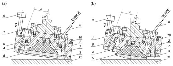
Figure 1.
Conceptual diagram of a dual-tool grinding head (1—grinding head body; 2—grinding wheel body; 3—ring-shaped bonded grinding wheel; 4—flexible abrasive disc holder; 5—flexible abrasive disc; 6—spring; 7—coolant feed channels; 8—coolant feed nozzle; 9—pneumatic actuator; 10—thrust bearing; 11—workpiece): (a) in the rough grinding setting; (b) in the finishing grinding setting [32].
The first stage of the work was to proceed with the design of a prototype dual-tool grinding head. During the design of the head, several changes were made with respect to the one in the patent. Among other things, the method of mounting the ceramic grinding wheel was changed, the number of springs was increased, and the method of extending the head was changed (the location of the bearing was changed from seating it on the head to actuators). The designed prototype head consisted of three basic components: an outer body, an inner body and a mounting adapter. All the components were connected using springs, bolts and nuts to mount a ceramic grinding wheel on the outer body and a prone grinding wheel on the inner body. Figure 2 shows a technical drawing of the designed prototype of the dual-tool grinding head.
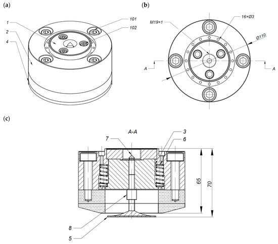
Figure 2.
Technical drawing of a prototype of a dual-tool grinding head (1—ER14 adapter, 2—outer body, 3—inner body, 4—Ø110 grinding wheel, 5—Ø50 3M Trizact® grinding wheel, 6—0.8 × 7.7 × 25 pressure spring, 7—centering shaft, 8—prone grinding wheel spacer, 101—M8 bolt, 102—M5 bolt): (a) isometric view; (b) top view; (c) A-A cross-section.
The following figures show a digital 3D model of the designed head. Figure 3a shows an isometric view of the head with a view of the outer body. In this body, the coolant supply channels to the machining zone are also designed. Figure 3b, on the other hand, shows the head with a view of the outer body, where you can see the springs and the way the ceramic grinding wheel is mounted.
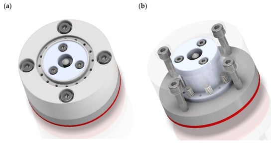
Figure 3.
The 3D digital model of a dual-tool grinding head: (a) external body view; (b) internal body view.
Next is a cross-sectional view of the digital 3D model of the grinding head in two positions. This is shown first in the position for coarse grinding with a ceramic grinding wheel (Figure 4a), and then in the position for finish grinding with a prone wheel extended (Figure 4b).
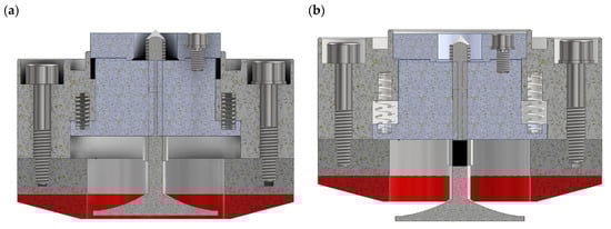
Figure 4.
The 3D digital model of a dual-tool grinding head: (a) in the coarse grinding setting; (b) in the finishing grinding setting.
2.2. Manufacture of the Dual-Tool Grinding Head
After the head was designed, the manufacturing of the head proceeded. All non-standard parts of the head were made using a HAAS ST-10 turning lathe (HAAS Automation, Oxnard, CA, USA), a HAAS VF-2 milling center (HAAS Automation, Oxnard, CA, USA) and a conventional chiseling machine. To make all elements of the dual-tool grinding head, necessary processes were used, such as the following:
- the process of turning the inner body of the head on a HAAS ST10 turning center;
- the process of milling the outer body of the head on a HAAS VF2 milling center;
- the process of milling the inner body of the head on a HAAS VF2 milling center;
- the process of milling the M19×1 mounting adapter on a HAAS VF2 milling center;
- the process of milling the pneumatic cylinder holder on the HAAS VF2 milling center;
- the process of chiseling the outer body of the head on a conventional chiseling machine made at the Tarnobrzeg Machine Tool Factory, model PABP-63.
Figure 5c shows all the fabricated components of the prototype dual-tool grinding head and the fully assembled grinding head. The coarse grinding process using the head used a custom-made ceramic grinding wheel made at ANDRE ABRASIVE ARTICLES limited liability company, limited partnership (Figure 5a). This grinding wheel measured 110 mm by 24 mm and has a 55 mm diameter bore. In addition, 4 M8 threaded inserts were designed for mounting it in the grinding head. On the other hand, the finishing grinding process used a prone grinding wheel from 3M Poland limited liability company, which had a diameter of 50 mm with a roloc mounting system and Trizact® grains [33] (Figure 5b). The characteristics of the presented grinding wheels are presented in Table 1.
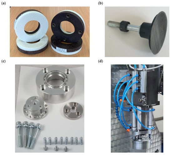
Figure 5.
(a) ceramic grinding wheel from ANDRE, type 3611-110×24×55-99A60K9V with four M8 threaded inserts; (b) a prone grinding wheel with Trizact® grains; (c) listing the components of dual-tool grinding head; (d) dual-tool grinding head mounted on the test bench.

Table 1.
Characteristic of grinding wheels.
The next step was to prepare a pneumatic system to control the position of the dual-tool grinding head. For this, three pneumatic actuators with fork joints, high-speed bearings and rollers, two power strips supplying air to the actuators and a controller regulating the position of the pneumatic actuators were used. The test stand of the completed pneumatic system and the dual-tool grinding head were then assembled, as shown in Figure 5d.
Figure 6a,b shows a view of the head with the actuators extended in the coarse grinding position, and Figure 6c,d shows the head with the actuators in the finishing grinding position. After the head body was prepared, the head was fully armed, i.e., the grinding wheels and the double head were installed. Views of the armed head in both positions are presented in Figure 6e,f.
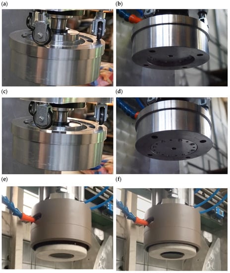
Figure 6.
View of the dual-tool grinding head: (a) in coarse grinding setting—top view; (b) in coarse grinding setting—bottom view; (c) in finishing grinding setting—top view; (d) in finishing grinding setting—bottom view; (e) fully equipped head in coarse grinding setting: (f) fully equipped head in the finishing grinding setting.
In the next step, the ceramic grinding wheel needed to be shaped. To this end, using Autodesk Inventor Professional 2023 with CAM Ultimate 2023 software (Mill Valley, CA, USA), a program was developed that controlled the machine tool to shape the grinding wheel at a 15° angle using a diamond dresser. The result is presented in Figure 7. Figure 8 shows the fully prepared two-tool head along with the coolant feed linking directly to the grinding zone.
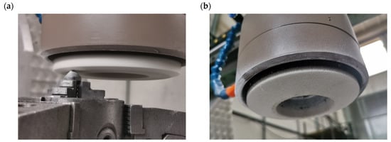
Figure 7.
Shaping a ceramic grinding wheel: (a) the process flow of shaping a ceramic grinding wheel using a diamond dresser; (b) the shaped ceramic wheel.
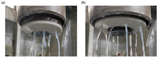
Figure 8.
A dual-tool grinding head prepared for the cutting process with coolant supply in the position for: (a) coarse grinding; (b) finish grinding.
2.3. Methodology of Experimental Research of the Grinding Process
After the grinding head was designed, fabricated, and rearmed, the grinding process proceeded. The workpiece was tool steel, which, prior to grinding, was milled with a 20 mm diameter ball mill at a rotational speed of 3900 rpm and a feed rate of 600 mm/min. Then, for the coarse grinding process (Figure 9a), the parameters used were 8100 rpm for the rotational speed, 1000 mm/min feed speed, 2 mm cutting width (parameter ae), and 0.04 mm cutting depth (parameter ap). On the other hand, for the finishing grinding process (Figure 9b), the parameters used were 15,000 rpm for the rotational speed, 1000 mm/min for the feed speed, 2 mm for the cutting width, and 0.1 mm for the cutting depth.
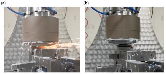
Figure 9.
View of the machining zone during the grinding process using a dual-tool grinding head: (a) coarse grinding using a ceramic grinding wheel; (b) finish grinding using a prone grinding wheel.
3. Results and Discussion
After the grinding process, the grinding wheels were analyzed using a VHX7000 digital microscope from KEYENCE INTERNATIONAL NV/SA (Mechelen, Belgium). First, the ceramic wheel (shown in Figure 10) was analyzed and then the prone wheel (Figure 11) was analyzed. The ceramic wheel shows numerous inclusions and dependencies with the workpiece material. Most likely, this is due to the insufficient openness of the grinding wheel structure and the adhesion of grinding products (mainly chips of workpiece material) to its active surface. In further stages of the work, it should be verified whether this problem is reduced by increasing the porosity (openness of the structure) of the grinding wheel and intensifying the cooling in order to more precisely reach the anti-adhesion agents contained in the coolant for the grinding zone. From the analysis of the microscopic image of the active surface of the ceramic grinding wheel, it is necessary to dress the wheel and reshape it to the desired shape before grinding further test samples.
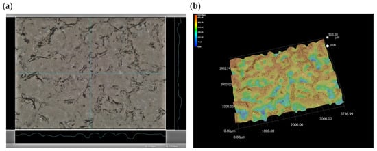
Figure 10.
Microscopic view of the active surface of the ceramic grinding wheel: (a) 80× magnification view of the grinding wheel; (b) 80× magnification analysis of the surface topography of the ceramic grinding wheel.
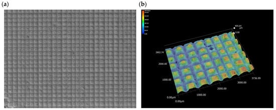
Figure 11.
Microscopic view of the active surface of a prone wheel with Trizact® grains: (a) view of the wheel at 20× magnification; (b) analysis of the surface topography of the prone wheel at 80× magnification.
Next, the active surface of a prone grinding wheel with Trizact® grains was analyzed. Trizact® grains are made up of multiple layers of precisely fractionated and uniformly arranged abrasive grains formed into the shape of identical pyramids. During operation, the pyramids gradually wear away, exposing new, sharp grains down to the base of the pyramid. Analysis of the active surface of the post-date grinding wheel shows that the grains are only moderately worn. On magnifications, single chipped grains are visible, but they are so few that the wheel is suitable for grinding subsequent samples while ensuring the full repeatability of the geometric structure of the machined surface.
Using a digital microscope, the machined surface was also analyzed. The images are presented in Figure 12. First, Figure 12a shows an image of the surface after milling. On the pre-presented surface, it is possible to see targeted machining traces resulting from the direction of rotation and the feed of the ball mill, and significantly distinguished zones resulting from the size of the feed parameter per tooth during milling. Next, Figure 12b shows an image of the surface after rough grinding. In this image, the grinding treatment with a ceramic grinding wheel removed a large enough layer of material that the milling marks were completely eliminated. Irregular machining marks have been removed from the surface and unidirectional (but still relatively deep) marks have been given, indicating that the grinding process took place at the point in which the ceramic grinding wheel’s circumferential slice contacted the workpiece material. Figure 12c shows an image of the surface after finish grinding. It shows machining marks that indicate that during the grinding process, the prone wheel adhered to the material with its entire circumference, which left multidirectional, intersecting machining marks on the material, but this time, with a much smaller depth. As a result, the surface gained a more regular shape and was smoothed out with respect to the state after the preceding step (coarse grinding).
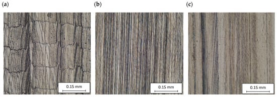
Figure 12.
Microscopic view of the machined surface: (a) view of the surface in its initial state after shape milling at 400× magnification; (b) view of the surface after shape milling and rough grinding at 400× magnification; (c) view of the surface after shape milling, rough grinding and finish grinding at 400× magnification.
A microtopography analysis of the machined surface was carried out using a Hommel-Tester T8000 contact profilometer (Hommelwerke GmbH, Villingen-Schwenningen, Germany). Using this measurement system, the surface topography of the specimens after the three machining steps was registered, and the results were processed in TalyMap Platinum 4.0 software (Digital Surf, Besançon, France). Figure 13 shows a view of the digital 3D model of the analyzed topography after successive machining stages, while Figure 14 shows the results from the developed Abbott-Fireston load curve analysis. During the analysis of the results, the most relevant surface roughness parameters were determined:
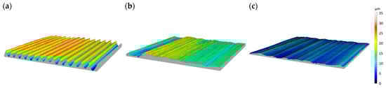
Figure 13.
The 3D microtopography view of the machined surface: (a) initial surface after contour milling; (b) surface after contour milling and coarse grinding; (c) post-surface after contour milling, coarse grinding and finish grinding.
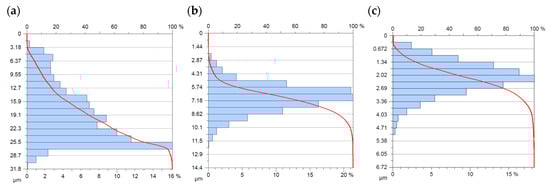
Figure 14.
Analysis of the Abbott-Fireston load-curve of machined surfaces: (a) after shape milling; (b) after shape milling and coarse grinding; (c) after shape milling, coarse grinding and finish grinding.
- Sa—arithmetic mean deviation of the surface,
- St—total height of the surface,
- Sds—density of summits of the surface,
- Sq—root-mean-square deviation of the surface,
- Str—texture aspect ratio of the surface,
- Spk—reduced peak height.
- The obtained results are summarized in Figure 15.
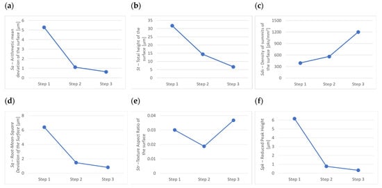 Figure 15. Summary graphs of selected surface roughness parameters after contour milling (Step 1), after contour milling and coarse grinding (Step 2), and after contour milling, coarse grinding and finish grinding (Step 3): (a) Sa—Arithmetic mean deviation of the surface; (b) St—Total height of the surface: (c) Sds—Density of summits of the surface; (d) Sq—Root-Mean-Square Deviation of the Surface; (e) Str—Texture Aspect Ratio of the surface; (f) Spk—Reduced Peak Height.
Analysis of the Abbott-Fireston load-bearing curve showed that with each successive machining of the workpieces, the magnitudes of the parameters describing the height of the surface roughness decreased. The values of parameters such as Sa, St, Sq and Spk decreased, as evidenced by a decrease in the arithmetic mean deviation of the surface from the mean surface of 5.30, 1.12, 0.63 μm, sequentially, reductions in the vertical distance between the peak of the highest apex and the lowest depression of the surface of 31. 8, 14.4 and 6.72 μm, reductions in the mean square deviation of the height of the surface irregularity from the reference plane of 6.39, 1.46, 0.81 μm, successively, and reductions in the height of the vertices of 6.16, 0.77, 0.33 μm, successively. This means that the evaluated surfaces in each successive machining step had increasingly lower roughness values, and thus were increasingly smoothed. The value of the Sds parameter, which provides information on the number of vertices per unit area, increased in successive processing stages (393, 563, 1203 pks/mm2), which means that, although the number of vertices increased, they were much smaller in height, as indicated by previous measurements. On the other hand, the value of the Str parameter, which describes the degree of directionality of the surface, first decreased from 0.03 to 0.0187, and then significantly increased from 0.0187 to 0.0367. This is due to the fact that in the first stage of the milling process, the machining marks were formed with a directed shape (transverse–longitudinal) that resulted from the trajectory of movement of the individual cutting edges of the milling cutter and the value of the kinematic parameters, including, mainly, the feed per tooth. In the second stage, the value of the Str parameter decreased to a level of 0.0187, as the roughing treatment smoothed out transverse irregularities and left only longitudinal machining marks. In the last stage, the value of the Str parameter increased to a level of 0.0367, which is above the condition of the first stage, because, as previously described, finishing machining with a prone wheel left multidirectional machining marks that were a result of the intersecting trajectories of the movement of the abrasive grains.
4. Conclusions
As a result of the design and verification work carried out, the following specific conclusions were formulated.
- The conducted tests of the grinding process showed a reduction in the values of the roughness parameters Sa (5.30, 1.12, 0.63 μm), St (31.8, 14.4, 6.72 μm), Sq (6.39, 1.46, 0.81 μm) and Spk (6.16, 0.77, 0. 33 μm), and an increase in the value of the parameter Sds (393, 563, 1203 pks/mm2) on the surface after machining in two stages, first for rough grinding and then for finishing; this was relative to the surface after the shaped milling process.
- The value of the Str parameter changed unevenly during the tests. It first decreased during coarse grinding (from a value of 0.03 to 0.0187), and then increased during finishing (from a value of 0.0187 to 0.0367). This is due to the fact that first, a grinding wheel was used that made linear contact with the workpiece during grinding, and then a wheel was used that ground the workpiece with its entire circumference.
- Microscopic analysis showed that the ceramic grinding wheel exhibited numerous inclusions and seizures with the workpiece material. Most likely, this is due to the insufficient openness of the grinding wheel structure and the adhesion of grinding products (mainly chips of workpiece material) to its active surface.
- Microscopic analysis of the active surface of the prone grinding wheel shows that the grains are only moderately worn. The magnifications show some chipped grains, but they are so few that the wheel is suitable for grinding subsequent samples while ensuring the full repeatability of the geometric structure of the machined surface.
The study confirmed that the use of a dual-tool grinding head is an innovative way to carry out the roughing and finishing grinding process in a single fixture. The conducted tests made it possible to determine both the strengths of the dual-tool grinding head, such as the possibility of complete machining in one clamping, and the weaknesses, such as the speed of rotation that the head can reach, the limitations of the tool geometry and the formation of deposits on the ceramic grinding wheel. This will allow for the elimination of detected imperfections and a further analysis of the strategies that could be used for integrating machining operations. In further research, it should be verified whether the problem of seizing the ceramic grinding wheel is reduced by increasing the porosity (openness of the structure) of the wheel and intensifying the cooling, in order to more precisely reach the anti-adhesive agents that are contained in the coolant for the grinding zone.
Author Contributions
Conceptualization, P.J. and K.N.; methodology, P.J. and K.N.; software, P.J., T.C. and W.Z.; validation, K.N.; formal analysis, P.J. and K.N.; investigation, P.J. and W.Z.; resources, K.N.; data curation, P.J., T.C. and W.Z.; writing—original draft preparation, P.J.; writing—review and editing, K.N.; visualization, P.J., T.C. and W.Z.; supervision, K.N.; project administration, K.N.; funding acquisition, K.N. All authors have read and agreed to the published version of the manuscript.
Funding
This research received no external funding.
Acknowledgments
The authors sincerely thank two companies for their cooperation. First, they thank ANDRE ABRASIVE ARTICLES limited liability company, limited partnership, including Monika Kwaśna, the customer service specialist, for her assistance in selecting and designing suitable ceramic grinding wheels. In addition, the authors would like to thank KEYENCE INTERNATIONAL (BELGIUM) NV/SA, including Michal Subsar, for his assistance in recording images using a digital microscope.
Conflicts of Interest
The authors declare no conflict of interest.
References
- Kshirsagar, N.; Tayade, R.M. A review of sequential micro-machining: State of art approach. In Materials Today: Proceedings; Elsevier: Amsterdam, The Netherlands, 2023; Volume 72, pp. 1394–1400. [Google Scholar]
- Bennett, J.; Garcia, D.; Kendrick, M.; Hartman, T.; Hyatt, G.; Ehmann, K.; You, F.; Cao, J. Repairing automotive dies with directed energy Deposition: Industrial application and life cycle analysis. J. Manuf. Sci. Eng. 2019, 141, 021019. [Google Scholar] [CrossRef]
- Krajnik, P.; Hashimoto, F.; Karpuschewski, B.; Silva, E.J.D.; Axinte, D. Grinding and fine finishing of future automotive powertrain components. CIRP Ann. 2021, 70, 589–610. [Google Scholar] [CrossRef]
- Azim, S.; Noor, S.; Khalid, Q.S.; Khan, A.M.; Pimenov, D.Y.; Ahmad, I.; Babar, A.R.; Pruncu, C.I. Sustainable manufacturing and parametric analysis of mild steel grade 60 by deploying CNC milling machine and Taguchi method. Metals 2020, 10, 1303. [Google Scholar]
- Nadolny, K.; Kapłonek, W. Analysis of flatness deviations for austenitic stainless steel workpieces after cient surface ma-chining. Meas. Sci. Rev. 2014, 14, 204–212. [Google Scholar]
- Wang, N.; Zhang, G.; Ren, L.; Yang, Z. Analysis of abrasive grain size effect of abrasive belt on material removal performance of GCr15 bearing steel. Tribol. Int. 2022, 171, 107536. [Google Scholar] [CrossRef]
- Habrat, W.F. Effect of Bond Type and Process Parameters on Grinding Force Components in Grinding of Cemented Carbide. Procedia Eng. 2016, 149, 122–129. [Google Scholar] [CrossRef]
- Guo, B.; Zhao, Q.; Fang, X. Precision grinding of optical glass with laser micro-structured coarse-grained diamond wheels. J. Mater. Process. Technol. 2014, 214, 1045–1051. [Google Scholar] [CrossRef]
- Wang, R.X.; Zhou, K.; Yang, J.Y.; Ding, H.H.; Wang, W.J.; Guo, J.; Liu, Q.Y. Effects of abrasive material and hardness of grinding wheel on rail grinding behaviors. Wear 2020, 454, 203332. [Google Scholar] [CrossRef]
- Yang, C.; Jiang, X.; Zhang, W.; Wang, X. Enhancing stress corrosion cracking resistance of machined surface via surface mechanical grinding treatment for AISI 316 L stainless steel. Mater. Charact. 2022, 194, 112493. [Google Scholar] [CrossRef]
- Chen, M.; Dai, H. Molecular dynamics study on grinding mechanism of polycrystalline silicon carbide. Diam. Relat. Mater. 2022, 130, 109541. [Google Scholar] [CrossRef]
- Przybylski, W. Integrated production technology of cylindrical surfaces by turning and burnishing. Adv. Manuf. Sci. Technol. 2016, 40, 29–42. [Google Scholar]
- Li, J.; Zou, L.; Luo, G.; Wang, W.; Lv, C. Enhancement and evaluation in path accuracy of industrial robot for complex surface grinding. Robot. Comput.-Integr. Manuf. 2023, 81, 102521. [Google Scholar] [CrossRef]
- Poppeova, V.; Uricek, J.; Bulej, V. Trends in the area of multitasking machine tools. In DAAAM International Scientific Book; DAAAM International: Vienna, Austria, 2011; Chapter 19; pp. 227–242. ISBN 978-3-901509-84-1. ISSN 1726-9687. [Google Scholar] [CrossRef]
- Nagae, A.; Muraki, T.; Yamamoto, H. History and Current Situation Situation of Multi-Tasking Machine Tools; Yamazaki Mazak Corporation: Takeda, Japan, 2012. [Google Scholar]
- Klocke, F.; Roderburg, A.; Zeppenfeld, C. Design methodology for hybrid production processes. Procedia Eng. 2011, 9, 417–430. [Google Scholar] [CrossRef]
- Lauwers, B.; Klocke, F.; Klink, A.; Tekkaya, A.E.; Neugebauer, R.; Mcintosh, D. Hybrid processes in manufacturing. CIRP Ann. Manuf. Technol. 2014, 63, 561–583. [Google Scholar] [CrossRef]
- Ding, S.; Zhang, H.; Guo, E.; Wu, W.; Zhang, Y.; Song, A. Integrated roughing, finishing and chamfering turning process of toroidal worm manufacture on a general CNC lathe. J. Manuf. Process. 2021, 70, 341–349. [Google Scholar] [CrossRef]
- Cai, Y.; Starly, B.; Cohen, P.; Lee, Y.S. Sensor data and information fusion to construct digital-twins virtual machine tools for cyber-physical manufacturing. Procedia Manuf. 2017, 10, 1031–1042. [Google Scholar] [CrossRef]
- Turning and milling machining center CTX gamma 2000 TC. Available online: https://pl.dmgmori.com/produkty/obrabiarki/toczenie/obrobka-tokarsko-frezarska/ctx-tc/ctx-gamma-2000-tc (accessed on 4 December 2022).
- Seidel, A.; Finaske, T.; Straubel, A.; Wendrock, H.; Maiwald, T.; Riede, M.; Lopez, E.; Brueckner, F.; Leyens, C. Additive manufacturing of powdery Ni-based superalloys Mar-M-247 and CM 247 LC in hybrid laser metal deposition. Metall. Mater. Trans. A Phys. Metall. Mater. Sci. 2018, 49, 3812–3830. [Google Scholar] [CrossRef]
- Kledwig, C.; Perfahl, H.; Reisacher, M.; Brückner, F.; Bliedtner, J.; Leyens, C. Analysis of melt pool characteristics and process parameters using a coaxial monitoring system during directed energy deposition in additive manufacturing. Materials 2019, 12, 308. [Google Scholar] [CrossRef]
- Integrated Toolholders for CNC Lathe with a Driven Y Axis. Available online: https://www.mtmarchetti.com/ (accessed on 4 December 2022).
- Yang, Y.; Wan, M.; Zhang, W.H.; Li, Y. Chip thickness analysis in peripheral milling of curved surfaces with variable curvature considering cutter runout. Mater. Sci. Forum 2012, 697, 75–79. [Google Scholar] [CrossRef]
- Rodríguez, A.; González, M.; Pereira, O.; López de Lacalle, L.N.; Esparta, M. Edge finishing of large turbine casings using defined multi-edge and abrasive tools in automated cells. Int. J. Adv. Manuf. Technol. 2023, 124, 3149–3159. [Google Scholar] [CrossRef]
- González, H.; Calleja, A.; Pereira, O.; Ortega, N.; López de Lacalle, L.N.; Barton, M. Super Abrasive Machining of Integral Rotary Components Using Grinding Flank Tools. Metals 2018, 8, 24. [Google Scholar] [CrossRef]
- González, H.; Pereira, O.; Fernández-Valdivielso, A.; López de Lacalle, L.N.; Calleja, A.; Comparison of Flank Super Abrasive Machining, vs. Flank Milling on Inconel® 718 Surfaces. Materials 2018, 11, 1638. [Google Scholar] [CrossRef]
- Khanna, N.; Rodríguez, A.; Shah, P.; Pereira, O.; Rubio-Mateos, A.; López de Lacalle, L.N.; Ostra, T. Comparison of dry and liquid carbon dioxide cutting conditions based on machining performance and life cycle assessment for end milling GFRP. Int. J. Adv. Manuf. Technol. 2022, 122, 821–833. [Google Scholar] [CrossRef]
- Pereira, O.; Rodríguez, A.; Calleja-Ochoa, A.; Celaya, A.; López de Lacalle, L.N.; Fernández-Valdivielso, A.; González, H. Simulation of Cryo-cooling to Improve Super Alloys Cutting Tools. Int. J. Precis. Eng. Manuf. Green Technol. 2022, 9, 73–82. [Google Scholar] [CrossRef]
- Mikolajczyk, T.; Pimenov, D.Y.; Pruncu, C.I.; Patra, K.; Latos, H.; Krolczyk, G.; Mia, M.; Klodowski, A.; Gupta, M.K. Obtaining various shapes of machined surface using a tool with a multi-insert cutting edge. Appl. Sci. 2019, 9, 880. [Google Scholar] [CrossRef]
- Sinlah, A.; Handayani, D.; Voigt, R.C.; Hayrynen, K.; M’Saoubi, R.; Saldana, C. Effects of microstructure and strength on wear performance in rough milling of austempered ductile iron. Int. J. Cast Met. Res. 2016, 29, 62–67. [Google Scholar] [CrossRef]
- Plichta, J.; Nadolny, K. Dual-Tool Grinding Head. PL 230988. 2018. [Google Scholar]
- Product Catalogue, 3M Abrasive Technology, Work Smarter, Finish Faster. 2021. Available online: https://multimedia.3m.com (accessed on 4 December 2022).


Disclaimer/Publisher’s Note: The statements, opinions and data contained in all publications are solely those of the individual author(s) and contributor(s) and not of MDPI and/or the editor(s). MDPI and/or the editor(s) disclaim responsibility for any injury to people or property resulting from any ideas, methods, instructions or products referred to in the content. |
© 2023 by the authors. Licensee MDPI, Basel, Switzerland. This article is an open access article distributed under the terms and conditions of the Creative Commons Attribution (CC BY) license (https://creativecommons.org/licenses/by/4.0/).