
Mechanisms and Models of Attenuation of Shock Waves through Rock Formations

Abstract
:1. Introduction
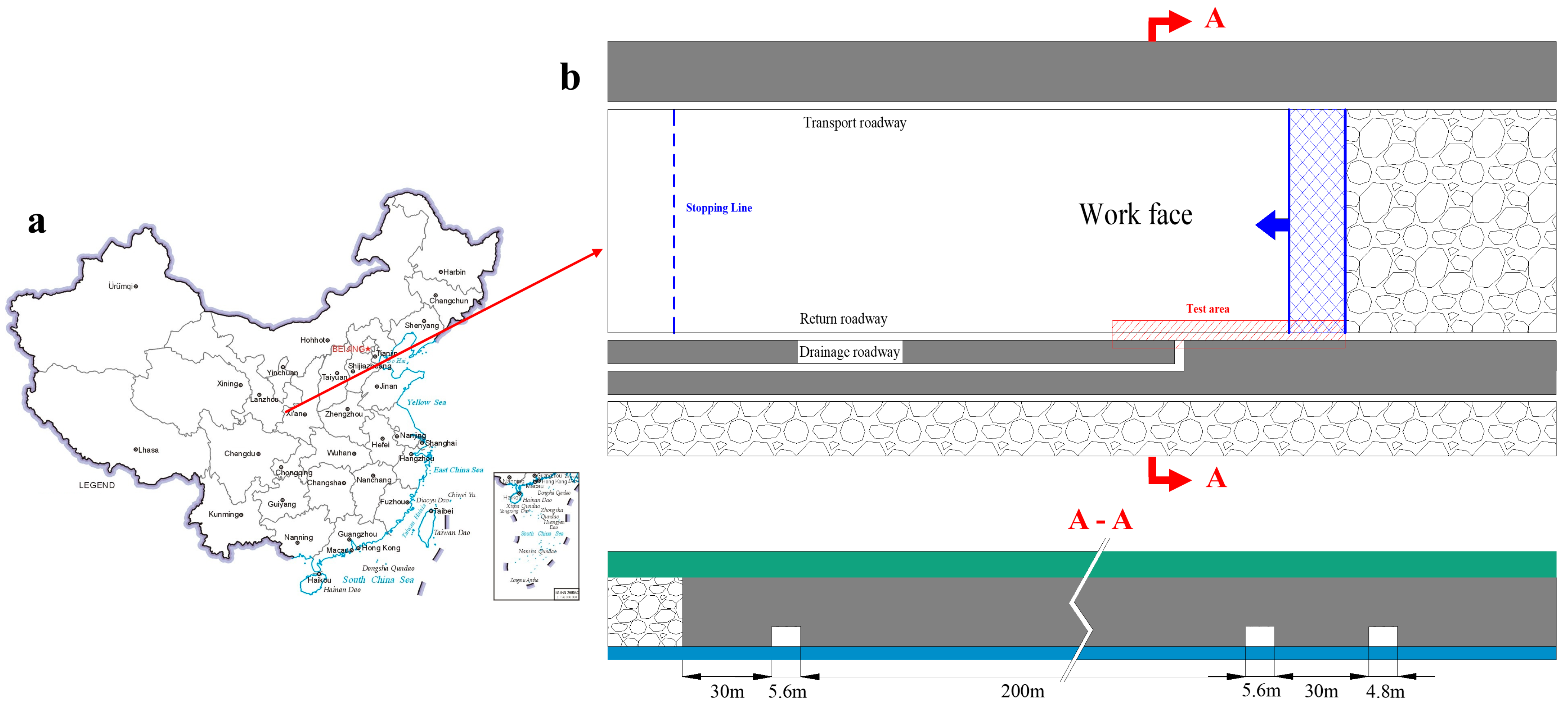
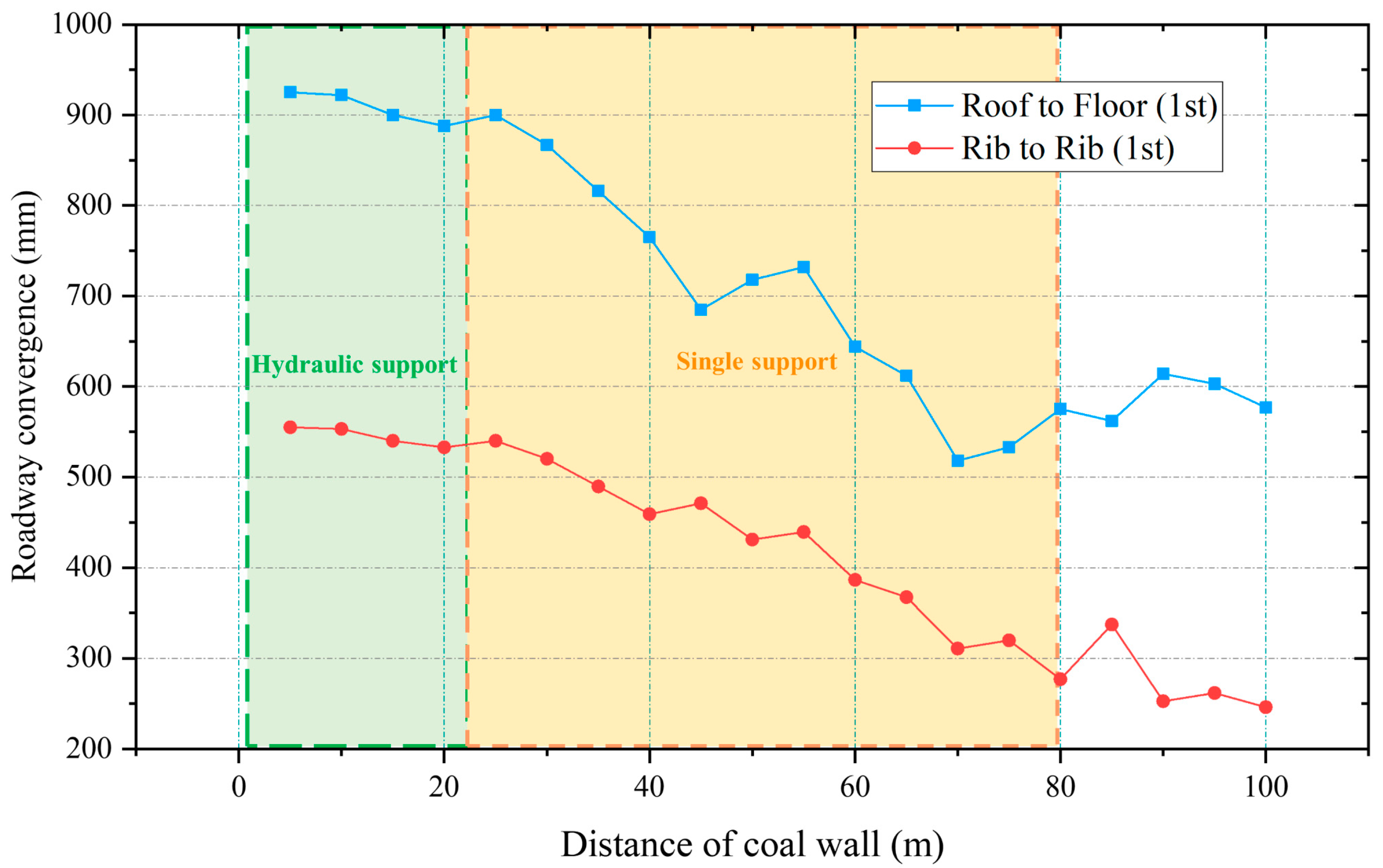
2. Case Study
Geologic Conditions
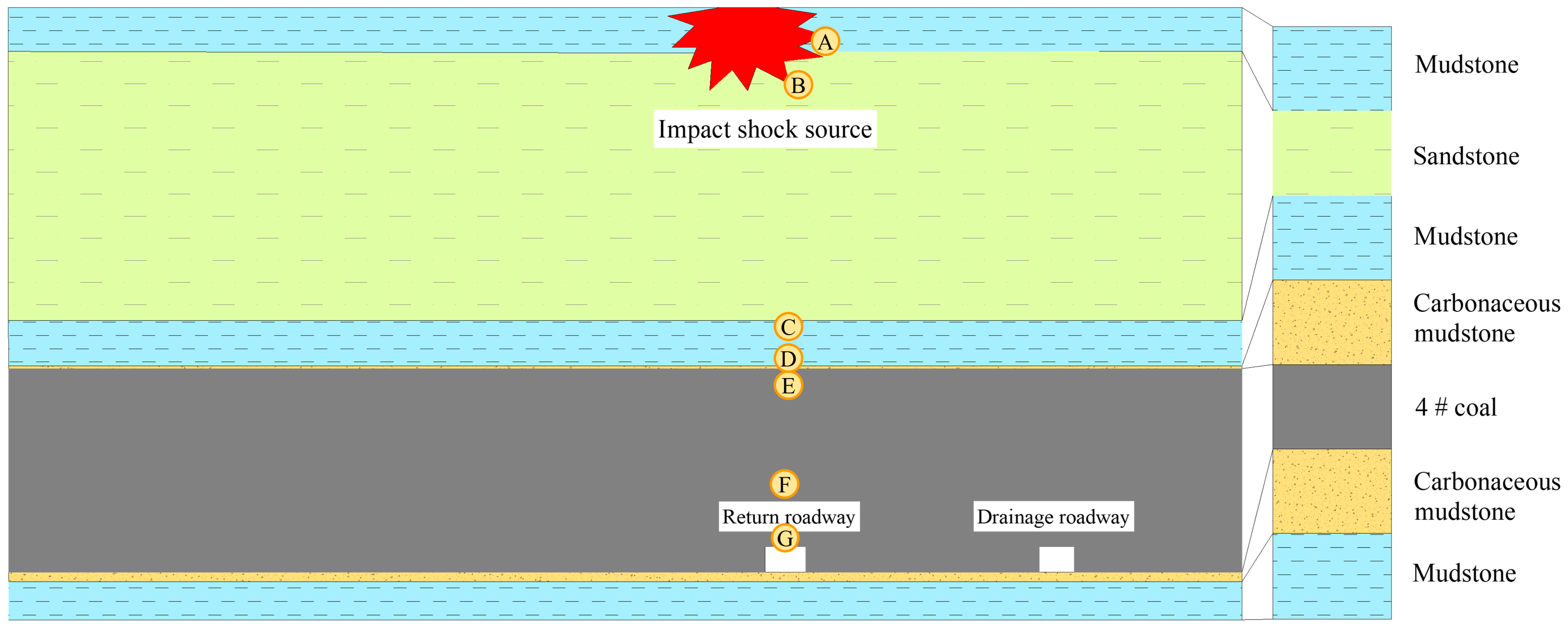
3. Numerical Simulation Study
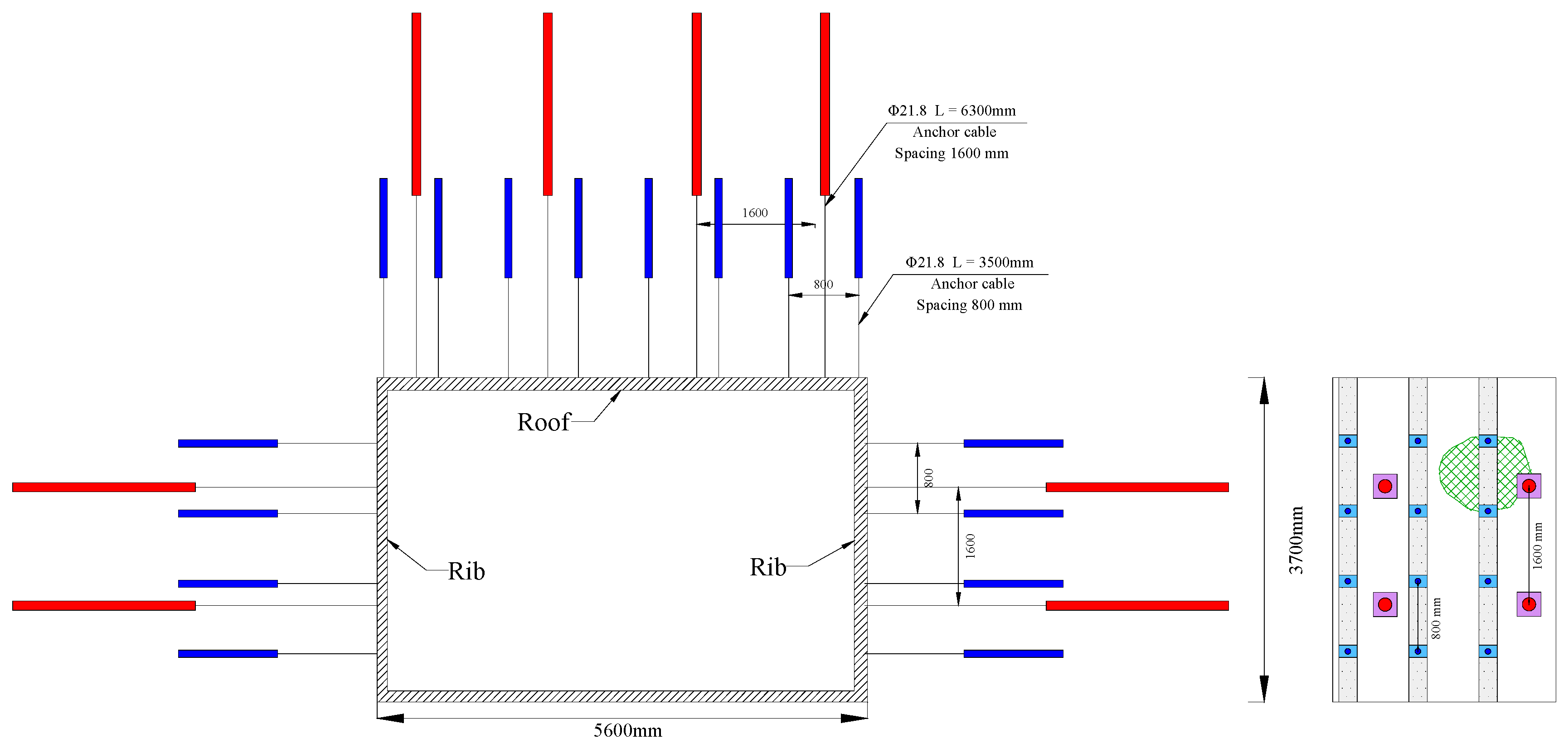
3.1. Model Building
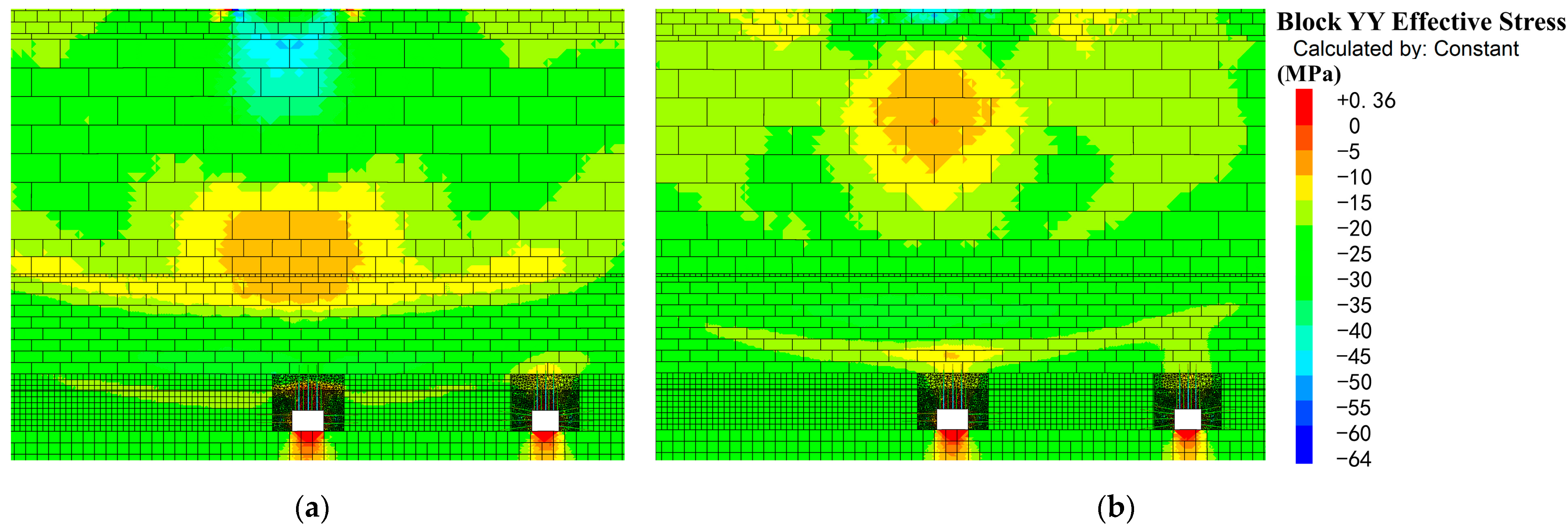
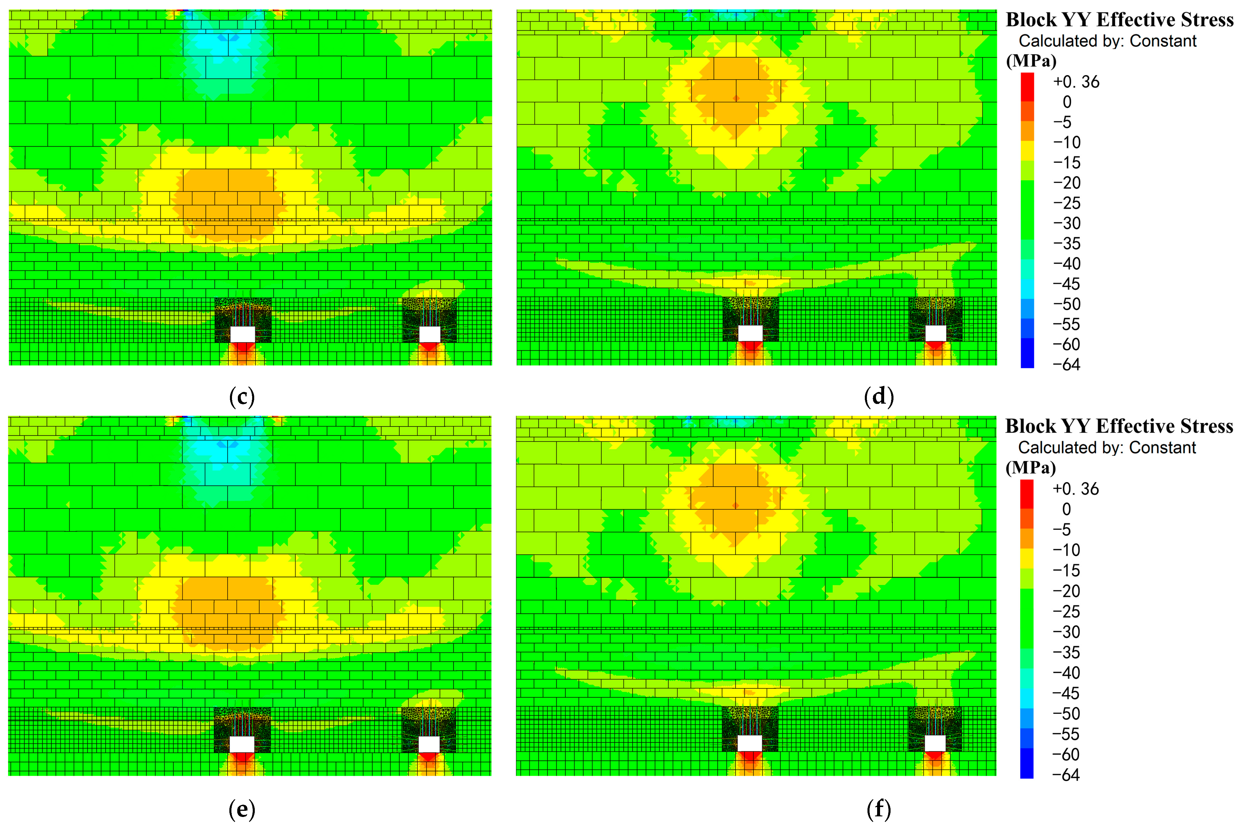
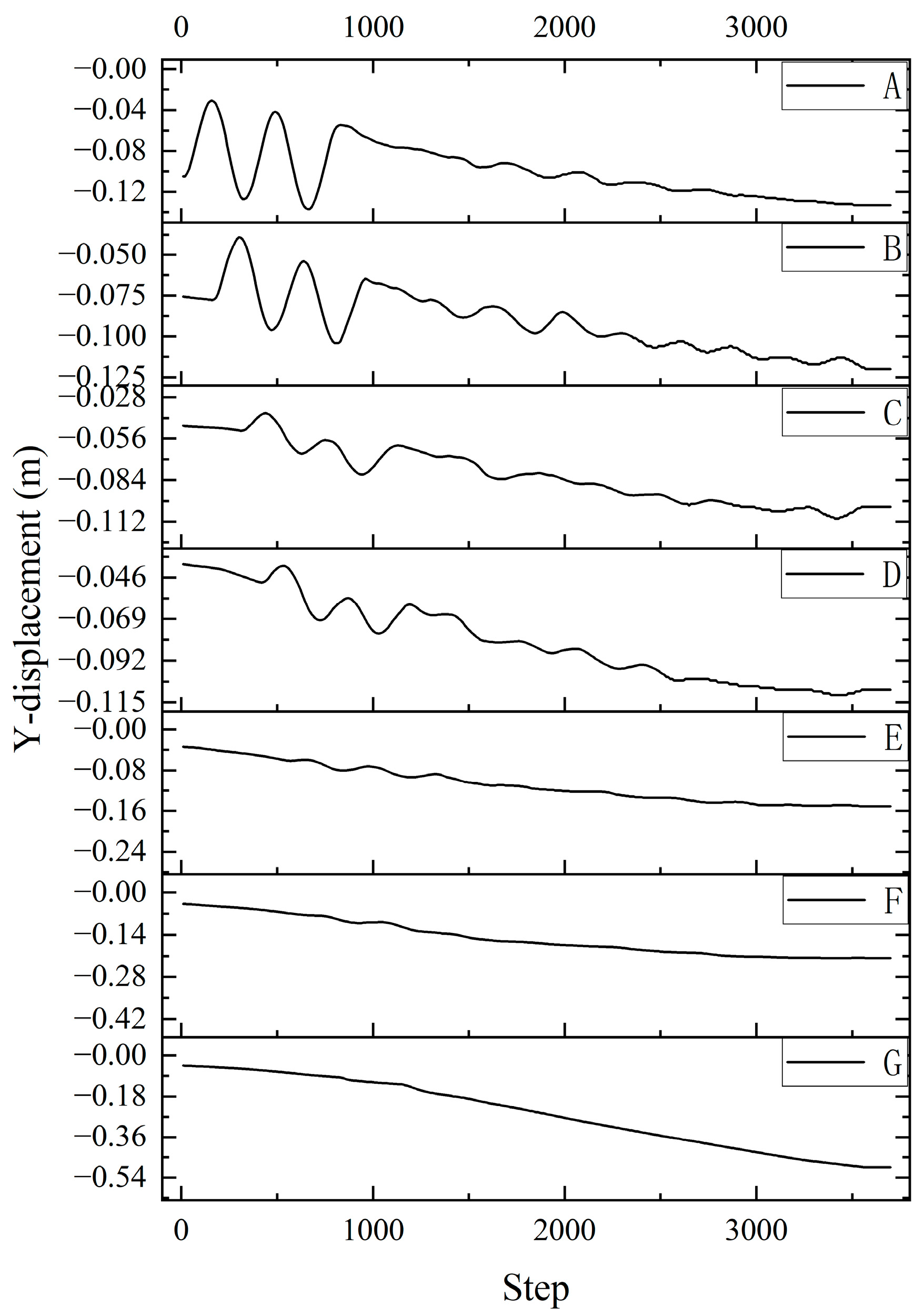
3.2. Results
- (1)
- There is a decreasing trend in the rate of attenuation during stress wave conduction.
- (2)
- There is a large difference in the attenuation coefficients during the passage through rock formations of the same properties.
- (3)
- The attenuation coefficients of the sandstone closer to the shock source are different from the second mudstone layer, which shows that different rock properties attenuate the shock waves to different degrees.

- (1)
- The axial force of the anchor cable remains almost unchanged during this process. It does not proactively change its own axial force to resist damage from the shock wave.
- (2)
- The loose areas of the roadway in the no-support conditions are much greater than in supported structures.
- (3)
- The support structures will reinforce the roadway, making it resist shock waves as intact rock would. They change the stress distribution around the roadway.
4. Discussion
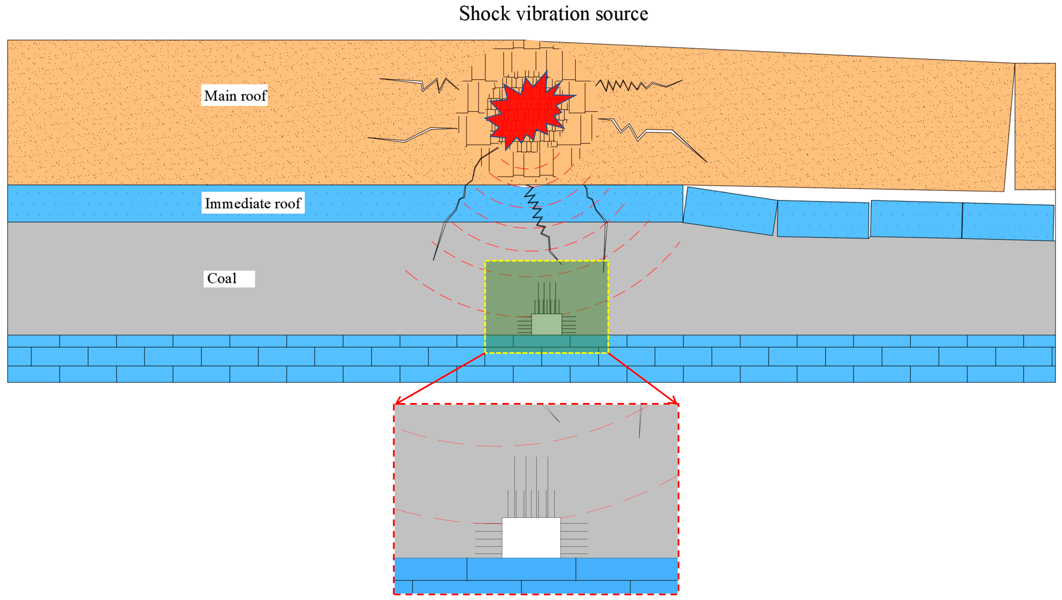
4.1. Shock Wave Disturbance Roadway Mechanism
- (a)
- When the shock wave spreads from the source to the surrounding rock of the roadway, the intensity gradually decreases.
- (b)
- There are different attenuation rates in rock formations with different properties.
- (c)
- During the transmission of the shock wave, the trend of the attenuation rate is decreasing.
- (d)
- Anchor cables cannot adaptively change their anchorage strength to stabilize the roof when the shock wave reaches the roadway. The role of the anchor cable is that it creates a complete structure with the roof of the roadway to resist shock waves.
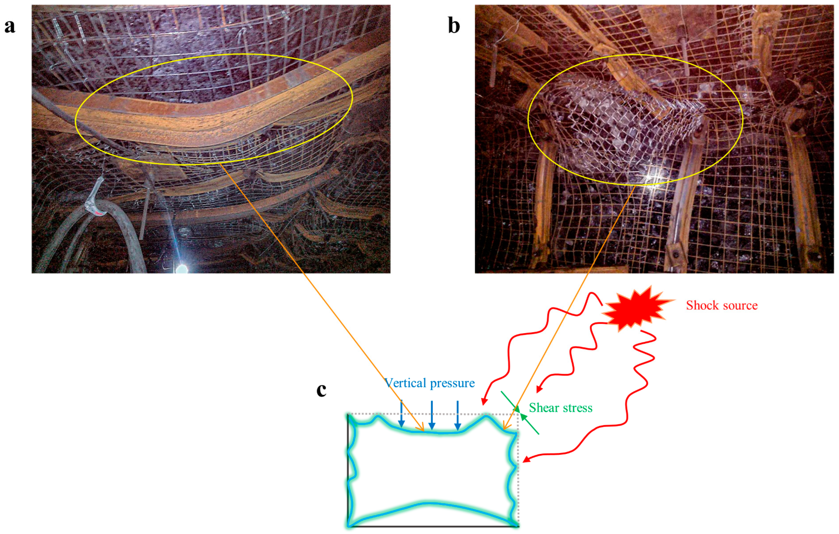
- (a)
- Due to the confines of the underground space, there is not enough space at the shock source for great displacements. The closer to the shock source, the higher the degree of damage to the rock.
- (b)
- For dynamic rocks, the roadway is a perfect free space. The rock damage is also dramatic here.
- (c)
- The subsidence of the roadway roof is an important factor in roadway damage.
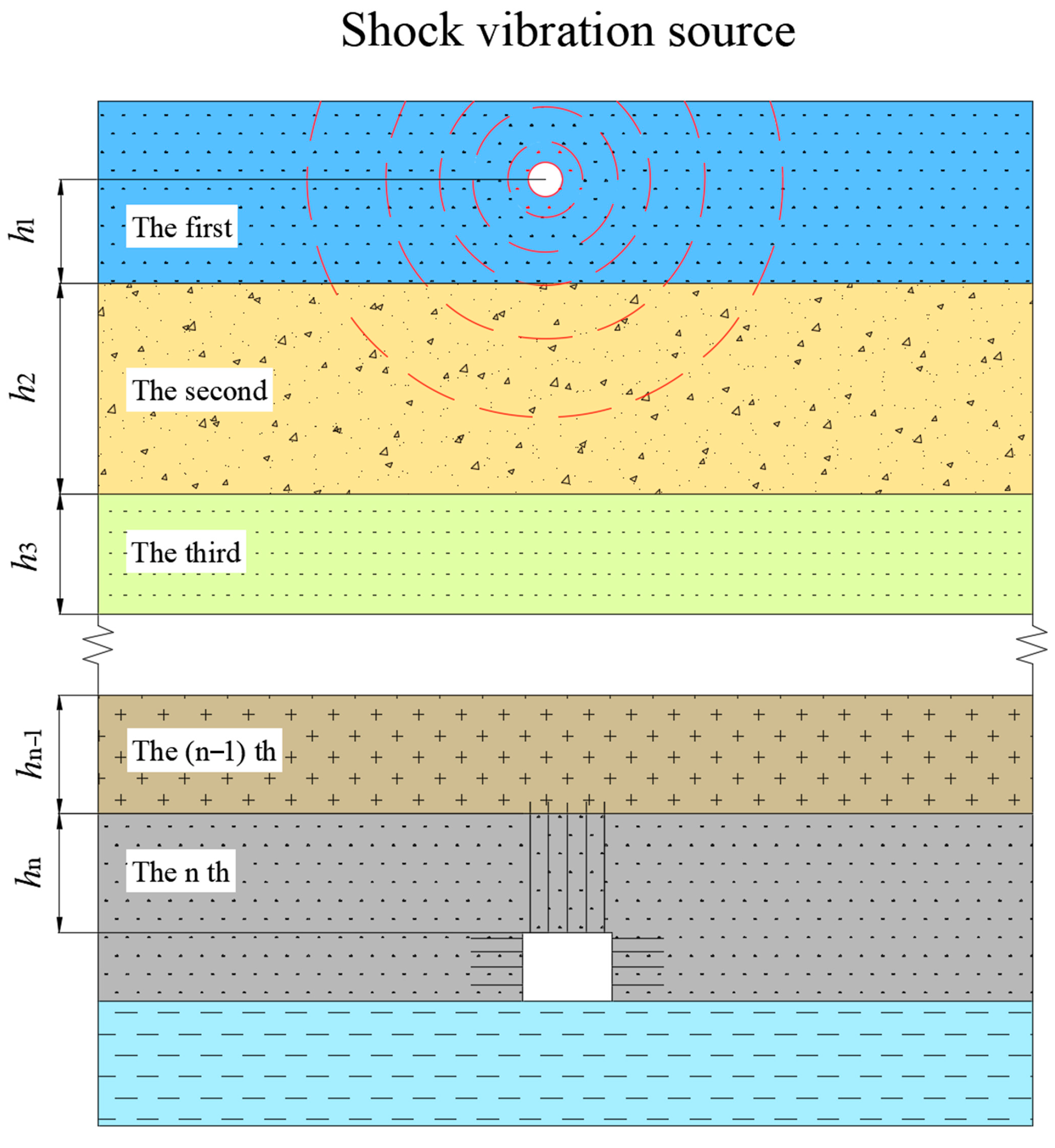
4.2. Model Establishment
5. Conclusions
- (1)
- The deformation and damage characteristics of the roadway under the superposition of static and dynamic loads were analyzed in the Hujiahe Coal Mine as a case study.
- (2)
- A numerical simulation model was established based on the production background of the Hujiahe mine, and the transmission characteristics of shock waves in the rock formation were analyzed. The shock wave is continuously attenuated as it passes from the impact shock source to the roadway. The distance between the rock formation and the impact shock source, and the rock properties are the main factors affecting the shock wave attenuation rate.
- (3)
- Based on the results of numerical simulations, a mechanical model of shock wave attenuation through the rock formation was established. An attenuation equation for the shock strength of the shock wave when it passes through the rock formation and reaches the roadway was derived.
Author Contributions
Funding
Institutional Review Board Statement
Informed Consent Statement
Data Availability Statement
Conflicts of Interest
References
- Li, T.; Cai, M.F.; Cai, M. A review of mining-induced seismicity in China. Int. J. Rock Mech. Min. Sci. 2007, 44, 1149–1171. [Google Scholar] [CrossRef]
- Ghorbani, M.; Shahriar, K.; Sharifzadeh, M.; Masoudi, R. A critical review on the developments of rock support systems in high stress ground conditions. Int. J. Min. Sci. Technol. 2020, 30, 555–572. [Google Scholar] [CrossRef]
- Junfeng, P.; Shuwen, W.; Hang, L.; Taotao, D. The Theory and Technology System to Preventing Rock Burst in Mining and Tunneling Space. In Proceedings of 2015 International Symposium—Safety and High Efficiency Mining in Coal; Qi, Q., Kang, H., Kuek, M., Eds.; St Plum-Blossom Press Pty Ltd.: Hawthorn East, Australia, 2015; pp. 125–136. [Google Scholar]
- Ma, T.-H.; Tang, C.-A.; Liu, F.; Zhang, S.-C.; Feng, Z.Q. Microseismic monitoring, analysis and early warning of rockburst. Geomat. Nat. Hazards Risk 2021, 12, 2956–2983. [Google Scholar] [CrossRef]
- Xue, R.; Liang, Z.; Xu, N. Rockburst prediction and analysis of activity characteristics within surrounding rock based on microseismic monitoring and numerical simulation. Int. J. Rock Mech. Min. Sci. 2021, 142, 104750. [Google Scholar] [CrossRef]
- Zhang, S.; Tang, C.; Wang, Y.; Li, J.; Ma, T.; Wang, K. Review on Early Warning Methods for Rockbursts in Tunnel Engineering Based on Microseismic Monitoring. Appl. Sci. 2021, 11, 10965. [Google Scholar] [CrossRef]
- Chen, X.; Li, L.; Wang, L.; Qi, L. The current situation and prevention and control countermeasures for typical dynamic disasters in kilometer-deep mines in China. Saf. Sci. 2019, 115, 229–236. [Google Scholar] [CrossRef]
- Zhou, J.; Li, X.; Mitri, H.S. Evaluation method of rockburst: State-of-the-art literature review. Tunn. Undergr. Space Technol. 2018, 81, 632–659. [Google Scholar] [CrossRef]
- Gao, M.-S.; Dou, L.-M.; Xie, Y.-S.; Gao, J.; Zhang, L.-S. Latest progress on study of stability control of roadway surrounding rocks subjected to rock burst. Procedia Earth Planet. Sci. 2009, 1, 409–413. [Google Scholar] [CrossRef] [Green Version]
- Sainoki, A.; Emad, M.Z.; Mitri, H.S. Study on the efficiency of destress blasting in deep mine drift development. Can. Geotech. J. 2017, 54, 518–528. [Google Scholar] [CrossRef] [Green Version]
- Afraei, S.; Shahriar, K.; Madani, S.H. Statistical analysis of rock-burst events in underground mines and excavations to present reasonable data-driven predictors. J. Stat. Comput. Simul. 2017, 87, 3336–3376. [Google Scholar] [CrossRef]
- Cui, Z.; Chanda, E.; Zhao, J.; Wang, Z. Stress distribution characteristics in the vicinity of coal seam floor. In Proceedings of the 2017 3rd International Conference on Environmental Science and Material Application (esma2017), Vols 1–4; Iop Publishing Ltd.: Bristol, UK, 2008; Volume 108, p. 032056. [Google Scholar] [CrossRef]
- Li, Y.; Zhou, C. Rockburst Inducement Mechanism and Its Prediction Based on Microseismic Monitoring. Geofluids 2021, 2021, 4028872. [Google Scholar] [CrossRef]
- Di, Y.; Wang, E. Rock Burst Precursor Electromagnetic Radiation Signal Recognition Method and Early Warning Application Based on Recurrent Neural Networks. Rock Mech. Rock Eng. 2021, 54, 1449–1461. [Google Scholar] [CrossRef]
- Feng, G.; Lin, M.; Yu, Y.; Fu, Y. A Microseismicity-Based Method of Rockburst Intensity Warning in Deep Tunnels in the Initial Period of Microseismic Monitoring. Energies 2020, 13, 2698. [Google Scholar] [CrossRef]
- Zhang, M.; Jiang, F. Rock burst criteria and control based on an abutment-stress-transfer model in deep coal roadways. Energy Sci. Eng. 2020, 8, 2966–2975. [Google Scholar] [CrossRef]
- Gao, M.; He, Y.; Xu, D.; Yu, X. A New Theoretical Model of Rock Burst-Prone Roadway Support and Its Application. Geofluids 2021, 2021, 5549875. [Google Scholar] [CrossRef]
- Wang, Z.-Y.; Dou, L.-M.; Wang, G.-F. Mechanism Analysis of Roadway Rockbursts Induced by Dynamic Mining Loading and Its Application. Energies 2018, 11, 2313. [Google Scholar] [CrossRef] [Green Version]
- Cai, W.; Bai, X.; Si, G.; Cao, W.; Gong, S.; Dou, L. A Monitoring Investigation into Rock Burst Mechanism Based on the Coupled Theory of Static and Dynamic Stresses. Rock Mech. Rock Eng. 2020, 53, 5451–5471. [Google Scholar] [CrossRef]
- Gao, M.-T.; Song, Z.-Q.; Duan, H.-Q.; Xin, H.-Q.; Tang, J.-Q. Mechanical Properties and Control Rockburst Mechanism of Coal and Rock Mass with Bursting Liability in Deep Mining. Shock Vib. 2020, 2020, 8833863. [Google Scholar] [CrossRef]
- Lu, Z.; Ju, W.; Gao, F.; Feng, Y.; Sun, Z.; Wang, H.; Yi, K. A New Bursting Liability Evaluation Index for Coal—The Effective Elastic Strain Energy Release Rate. Energies 2019, 12, 3734. [Google Scholar] [CrossRef] [Green Version]
- Lu, Z.; Ju, W.; Gao, F.; Yi, K. Influence of Loading Rate on the Failure Characteristics of Composite Coal-Rock Specimens Under Quasi-static Loading Conditions. Rock Mech. Rock Eng. 2022, 55, 909–921. [Google Scholar] [CrossRef]
- Dai, L.; Pan, Y.; Li, Z.; Wang, A.; Xiao, Y.; Liu, F.; Shi, T.; Zheng, W. Quantitative mechanism of roadway rockbursts in deep extra-thick coal seams: Theory and case histories. Tunn. Undergr. Space Technol. 2021, 111, 103861. [Google Scholar] [CrossRef]
- Li, L.; Zhang, H.; Pan, Y.; Ju, X.; Tang, L.; Li, M. Influence of stress wave-induced disturbance on ultra-low friction in broken blocks. Int. J. Coal Sci. Technol. 2022, 9, 22. [Google Scholar] [CrossRef]
- Gao, F.; Stead, D.; Kang, H. Numerical Simulation of Squeezing Failure in a Coal Mine Roadway due to Mining-Induced Stresses. Rock Mech. Rock Eng. 2015, 48, 1635–1645. [Google Scholar] [CrossRef]
- Guo, G.; Kang, H.; Qian, D.; Gao, F.; Wang, Y. Mechanism for Controlling Floor Heave of Mining Roadways Using Reinforcing Roof and Sidewalls in Underground Coal Mine. Sustainability 2018, 10, 1413. [Google Scholar] [CrossRef] [Green Version]
- Zheng, C.; Zheng, J.; Peng, X.; Zhou, L. Study on Failure Characteristics and Rock Burst Mechanism of Roadway Roof under Cyclic Dynamic Load. Shock Vib. 2021, 2021, 7074350. [Google Scholar] [CrossRef]
- Gao, M.; Zhao, Y.; Chen, X.; Lu, Q.; Liu, A. Destruction mechanism of rock burst in mine roadways and their prevention. Disaster Adv. 2013, 6, 34–43. [Google Scholar]
- Yun-liang, T.; Ze, Z.; Chuan-le, M. Rock Burst Disaster induced by Mining Abutment Pressure. Disaster Adv. 2012, 5, 378–382. [Google Scholar]
- Wang, P.; Zhang, N.; Kan, J.; Xu, X.; Cui, G. Instability Mode and Control Technology of Surrounding Rock in Composite Roof Coal Roadway under Multiple Dynamic Pressure Disturbances. Geofluids 2022, 2022, 8694325. [Google Scholar] [CrossRef]
- Yan, H.; Deng, X.; Fang, K.; Guo, S.; Li, W. Roof Catastrophe Mechanism of Roadways with Extra-thick Coal Seam and its Controlling Countermeasures. Disaster Adv. 2013, 6, 236–243. [Google Scholar]

| Location | Lithology | Thickness (m) | Bulk (GPa) | Density (kg/m3) | Shear (GPa) | Frictional Angle (°) | Cohesion (MPa) | Tension (MPa) |
|---|---|---|---|---|---|---|---|---|
| Roof | mudstone | 5.58 | 15 | 2300 | 7 | 30 | 2 | 1.84 |
| Main roof | sandstone | 35.95 | 22 | 2600 | 14 | 39 | 10.2 | 1.2 |
| Roof | mudstone | 6.03 | 15 | 2300 | 7 | 30 | 2 | 1.84 |
| Immediate roof | carbonaceous mudstone | 0.45 | 15 | 2500 | 4 | 36 | 4.98 | 2.01 |
| Coal seam | coal | 23 | 10 | 1290 | 5 | 28 | 1.5 | 0.55 |
| Immediate floor | carbonaceous mudstone | 1.1 | 15 | 2500 | 4 | 36 | 4.98 | 2.01 |
| Floor | mudstone | 4.79 | 15 | 2300 | 7 | 30 | 2 | 1.84 |
Disclaimer/Publisher’s Note: The statements, opinions and data contained in all publications are solely those of the individual author(s) and contributor(s) and not of MDPI and/or the editor(s). MDPI and/or the editor(s) disclaim responsibility for any injury to people or property resulting from any ideas, methods, instructions or products referred to in the content. |
© 2023 by the authors. Licensee MDPI, Basel, Switzerland. This article is an open access article distributed under the terms and conditions of the Creative Commons Attribution (CC BY) license (https://creativecommons.org/licenses/by/4.0/).
Share and Cite
Zhao, S.; Gao, M.; Xu, D.; Yu, X.; Zhao, H. Mechanisms and Models of Attenuation of Shock Waves through Rock Formations. Appl. Sci. 2023, 13, 4526. https://doi.org/10.3390/app13074526
Zhao S, Gao M, Xu D, Yu X, Zhao H. Mechanisms and Models of Attenuation of Shock Waves through Rock Formations. Applied Sciences. 2023; 13(7):4526. https://doi.org/10.3390/app13074526
Chicago/Turabian StyleZhao, Shifan, Mingshi Gao, Dong Xu, Xin Yu, and Hongchao Zhao. 2023. "Mechanisms and Models of Attenuation of Shock Waves through Rock Formations" Applied Sciences 13, no. 7: 4526. https://doi.org/10.3390/app13074526