Abstract
A double-layer element consisting of a spider-shaped structure on the top layer and a pair of concave arms with a circular ring on the middle layer is proposed for the wideband reflectarray with low cross-polarization characteristics. The unit cell offers a linear and wider phase range of 800. Based on the proposed unit cell, an offset-fed reflectarray with an octagonal aperture comprising 6769 unit cells is constructed at 11.725 GHz. The reflectarray offers 1 dB and 3 dB gain bandwidths of 25.2% and 32.3%, respectively, with an operating frequency range of 10–13.85 GHz. A peak gain of 31.2 dBi with an aperture efficiency of 42% is achieved. The cross-polarization levels are less than the co-polarization by 40 dB over the entire operating band.
1. Introduction
Reflectarray antennas (RA) have been studied intensively due to their promising features, owing to their low profile, reduced cost, and ease of manufacture and deployment [1,2]. However, they suffer from narrow bandwidth, which is predominantly due to the nonlinear reflection phase response of the elements. Numerous techniques have been reported in the literature to enhance bandwidth performance, such as an air gap between the ground and substrate [3,4], thick substrates [5,6], multi-resonating elements [7], meander-shaped concentric squares [8], fractal elements [9], multi-layered multi-resonating structures [10], subwavelength elements [11], hybrid elements [12,13], dual-cut-ring elements [14], and circular ring and diagonal patch ring combination elements [15]. The above techniques remarkably improve bandwidth. In some designs, an additional layer of air is used for a slow phase variation [3,4], at which point it is hard to maintain a constant level of air gap across the wider aperture.
Recently, in [16] a unit cell that comprises a multi-resonating structure with a cross dipole enclosed by cross-dipole loops generated a wide-phase variation of 802 that has a variable phase sensitivity with a maximum value of 300/mm. In this design, foam is used between the substrate and the ground. Similarly, the authors in [17] proposed a unit cell that has a wider and linear phase range of 700 that is obtained by applying a Minkowski fractal-shaped reflector with an aperture-coupled phasing stub.
Another important issue is the cross-polarization (x-pol) discrimination that causes the loss of energy. The x-pol can be reduced by providing a proper feed, and the design of the unit cell. The authors in [18] presented a single-layer structure that consists of a slotted rectangular patch with concave rectangular arms. The x-pol can be reduced by a special arrangement of elements that is −26 dB. However, the phase variation of 360 is realized. Another design in [19] realized a wideband single-layer structure that comprises a slotted rectangular patch with concave rectangular arms. The structure features linear phase variations of 360 and x-pol level of −32 dB. The authors in [20] presented a combination of a spiral dipole and four square rings that achieves a wider gain bandwidth of 35% (1 dB) and aperture efficiency of 55%. However, the cross-pol level is −30 dB. A reflectarray based on a windmill-shaped unit cell that features a 3 dB band of 35.7% with an efficiency of 51.7% is presented in [21]. The cross-pol level is −25 dB less than the co-pol level. High aperture efficiency of 62% is achieved with a better cross-pol level of −36 dB by employing a 0.15 element in [22]. The x-pol can be reduced by designing the unit cell to have current in only a single polarization. However, it becomes difficult to realize the single polarized current when designing multi-resonating multi-layered unit cells, as the currents of closely multi-resonant elements are dependent on each other. In this paper, a new subwavelength element comprising a double-layer unit cell for a broadband RA is proposed. The unit cell offers a linear and wider phase response of 800. The slopes of the reflection phases at different frequencies are nearly equal, to realize a wide-bandwidth performance. Based on the proposed unit cell structure, an offset-fed RA is designed with the horn feed located at the mirror image of the beam at 30. The 3 dB gain bandwidth (GBW) performance of 32% is achieved. Furthermore, the RA provides a low level of x-pol that has been reduced by canceling out the current in an x-pol direction in the individual unit cell rather than the special arrangement of the unit cells in [18] on the RA aperture.
2. Unit Cell Structure and Characterization
Figure 1 illustrates the configuration of the proposed unit cell. A spider-shaped structure is printed on the top layer of substrate I (Taconic RF 35 of thickness = 0.76 mm, = 3.5, tand = 0.0018), which is composed of a dipole and three iterations of the pairs of circular arcs, and the middle layer is printed on the bottom layer of substrate I that comprises a circular ring along with a pair of concave arms. The middle layer and ground are separated by substrate II (Taconic RF 35 of thickness = 1.52 mm, = 3.5, tand = 0.0018). Both the substrates are combined through an adhesive layer of thickness 0.09 mm and permittivity 4.4. The unit cell has a periodicity of 8 mm (0.31) in both the x- and y-directions, where is the free space wavelength at 11.725 GHz.
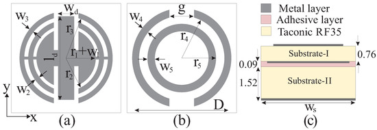
Figure 1.
Geometry of the proposed unit cell design: (a) Top layer. (b) Middle layer. (c) Side view. [r = variable, r = r + 0.6, r = r + 1.255, r = r + 1.3, r = r + 0.7, gap = r, w = w = w = 0.2*r, w = w = 0.3*r, w = 0.65*r, l = 2*r + 2.51, h = 1.52, h = 0.09, h = 0.76, D = 2*(r + w) = 2.54*r + 2.6].
To extract the phase reflection characteristics of the unit cell, an infinite-array approach is performed in ANSYS HFSS. The periodic boundary conditions on the side walls are master–slave, and a Floquet port is used for excitation [23]. The magnitude and phase reflection of the unit cell is illustrated in Figure 2. Under normal incidence, the unit cell is simulated and optimized at 11.725 GHz to achieve linear phase variations with a sufficient phase range over 800.
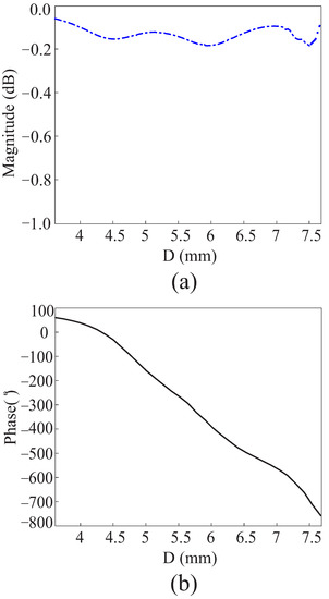
Figure 2.
Floquet port simulation of the unit cell at 11.725 GHz: (a) Magnitude of the reflection coefficient. (b) Phase of the reflection coefficient.
The magnitude of the maximum reflection coefficient in the bandwidth is −0.19 dB. The step-by-step evaluation of the unit cell is given in Figure 3. It should be noted that the middle layer is the same for all cases, as given in Figure 1b. In the first case(i), the reflection phase variation of 500 is achieved, using the dipole on the top layer. In the second case (ii) (dipole with first iteration (Itr1)), a reflection phase variation of nearly 800 is obtained, but the slope is dramatically changing. The slope gets better until D = 7 mm in the third case (iii) (dipole with Itr1 and Itr2) covering almost 800.
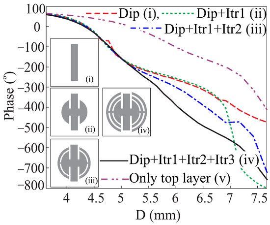
Figure 3.
Step-by-step evaluation of the unit cell.
Furthermore, checking the unit cell performance over the bandwidth, the normalized reflection phase curves for different frequencies are depicted in Figure 4. The phase curves are linear and insensitive to the frequency variation when D varies from 4.2 mm to 7 mm, which anticipates the broadband behavior of the unit cell. The effect of the various incident wave angles on the reflected phase performance is given in Figure 5, which shows a negligible phase variation with the angle of incidence. It is important to show the current distribution on the unit cell as it accounts for the low x-pol level. Figure 6a,b shows the current distribution on the top and middle layer of the unit cell at 11.725 GHz for the case when the dipole and iterations are not shorted with each other. The top-layer currents on the first and third iterations are symmetrical, which results in a complete single polarized net current. However, the dipole and second iteration carry asymmetrical currents that cause an increase in the x-pol level. Similarly, the currents on the concave arms in the middle layer are mirror images of each other, whereas the circular ring has a net counterclockwise current. In the figure, and represent the desired co-pol and x-pol currents on the unit cell. To avoid the x-pol current, the dipoles and iterations are shorted with each other, as shown in the proposed design. The current distributions are shown in Figure 6c,d on the top and middle layer of the unit cell, respectively. The net current on the top and middle layers exist only along the length of the dipole, whereas the components of all the currents that are orthogonal to the length of the dipole cancel each other out. Therefore, good performance can be anticipated in terms of the x-pol level.
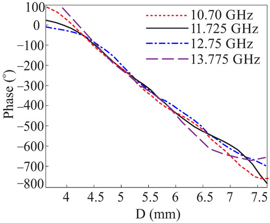
Figure 4.
Normalized reflection phase curves at different frequencies over the bandwidth.
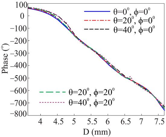
Figure 5.
Normalized reflection phase curves at 11.725 GHz for various oblique incidence.
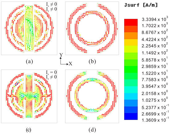
Figure 6.
Surface current on the unit cell at 11.725 GHz when the dipole is not shorted with iterations: (a) Top layer. (b) Middle Layer. and surface current on the unit cell at 11.725 GHz when the dipole and iterations are shorted with each other: (c) Top layer. (d) Middle Layer. [ and represents the co- and x-pol currents].
Furthermore, using Itr3 in the fourth case(iv), a reflection phase of 800 is achieved with insignificant variations in the slope after optimization. Finally, the middle layer in case (iv) is removed, which results in a total phase variation of 400 in case (v). From the above analysis, case (iv) provides the best performance with parameters given in Figure 1.
3. Reflectarray Antenna Implementation and Results
Based upon the new design of the unit cell, an RA is constructed as shown in Figure 7. An offset pyramidal horn is employed to illuminate the RA located at the mirror image of the beam at 30. The horn is fixed at the phase center of the RA at = 350 mm with coordinates () = (−175,0,303.108) mm that point to the center of the RA. The aperture of the RA is an octagonal shape with a maximum dimension of D = 456 mm. To avoid spillover losses, F/D = 0.765 is chosen to provide proper aperture illumination with an E-field edge taper of about −10 dB. The octagonal aperture is adapted because it has proper E-field edge tapering as compared to the rectangular aperture. To design the RA, the realized phase reflection of each element on the aperture regarding the specific direction of the beam can be obtained by the following equation [1]:
where is the wave number in free space, is the spatial phase delay from the phase center of the array to the ith element. and are the coordinates of the ith element on the aperture. and are the required beam directions in the space. is the distance between the phase center of the RA and the reference point (center of the RA aperture). In our case = 0, thus Equation (1) becomes
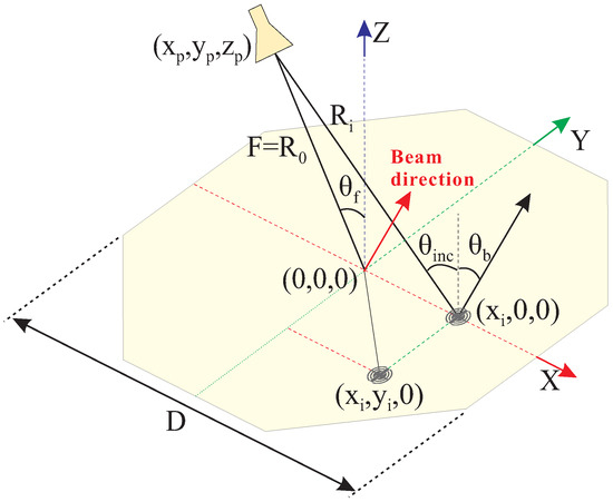
Figure 7.
Schematic representation of the reflectarray antenna and co-ordinate system.
Figure 8a shows the mechanical setup of the reflectarray antenna and its geometry. An 8 mm thick octagonal metallic jig of the same area as the reflectarray aperture is designed, and polycarbonate screws were used to assemble the reflectarray and jig. To rotate the horn antenna along the circular path, a rectangular strut that consists of parallel vertical arms made of steel holds the jig, and the horizontal arm which holds the horn antenna is made of plastic. The vertical steel arms have no significant effect on the co- and x-pol pattern. However, the horizontal arm has a considerable effect on the reflectarray performance. Therefore, it is made of non-conductive material. A fabricated prototype of the RA in the near-field measurement environment is shown in Figure 8b. The horn is mounted on the strut with the help of a holder. Figure 9 presents the simulated and measured co- and x-pol patterns in the azimuthal and elevation plane at 11.725 GHz. The measured radiation patterns agree very well with the simulated patterns. The x-pol levels in the main beam direction lie at around −10 dBi. The measured side lobe levels (SLL) are around 6 dB in both the azimuthal and elevation planes. The aperture efficiency and comparison of the measured and simulated gains of the proposed RA are plotted in Figure 10 for only the desired bandwidth.
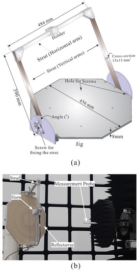
Figure 8.
(a) Mechanical setup and (b) Near-field measurement setup of the proposed reflectarray.
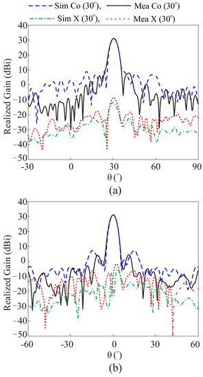
Figure 9.
Comparison of the simulated and measured co-pol patterns, and measured x-pol patterns at 11.725 GHz. (a) Azimuthal plane. (b) Elevation plane.
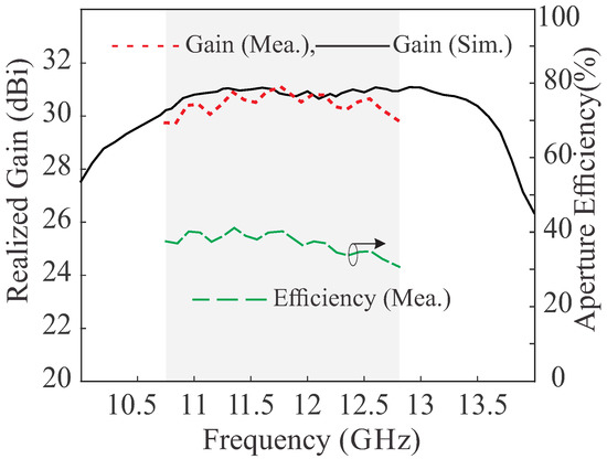
Figure 10.
Simulated and measured realized gain and aperture efficiency.
This shows that the measured peak gains of 31.2 dBi are achieved across the bandwidth. The differences in the measurements and simulations can be attributed to the fabrication tolerances and beam alignment during measurements. The RA peak aperture efficiency of 42% at 11.35 GHz is noted. Moreover, the simulated GBWs of 32% (3 dB) and 25.2% (1 dB) are obtained.
Table 1 compares the performance of the proposed RA with the previous literature. It should be kept in mind that RA of a high F/D ratio possesses high aperture efficiency. The reason for this is that as the distance between the feed and aperture increases, the amplitude distribution is more uniform. Another factor is that the phase error at the edges also reduces, which makes the GBW increase. Despite the larger aperture area and smaller F/D ratio, the proposed design has considerable GBW. The last two columns of the table that compare the x-pol level and SLL are the distinct features of the design that make it superior to the published work. The minimum x-pol level is attributed to the new structure of the unit cell that cancels the currents in the x-pol direction. The low SLLs authenticate the proper design of RA with the negligible effect of phase error on the collimation of reflected waves.

Table 1.
Comparison of the RA performance with the published work.
4. Conclusions
A double-layer wideband RA antenna is proposed in this study for the Ku-band satellite application. Each unit cell is composed of a spider-shaped structure on the top layer and a circular ring with a pair of concave arms on the middle layer. A wide range of linear phase variation of 800 is offered by the unit cell. The performance of the proposed RA antenna is verified through measurement and simulation results. The RA offers a 3 dB GBW almost constant around 32.2%. The maximum gain of RA 31 dBi with an aperture efficiency of 42% is achieved and the measured x-pol level is 40 dBi lower than the co-pol level. Thus, the design is more suitable for high-gain satellite applications.
Author Contributions
M.E., T.J., Y.Y., K.-Y.L. and K.C.H. contributed to conceptualization, articulation, original draft preparation, review, and the editing of the document. All authors have read and agreed to the published version of the manuscript.
Funding
This work was supported by Institute of Information & communications Technology Planning & Evaluation (IITP) grant funded by the Korea government(MSIT) (No022-0-007040002003, Development of 3D-NET Core Technology for High-Mobility Vehicular Service
Institutional Review Board Statement
Not applicable.
Informed Consent Statement
Not applicable.
Data Availability Statement
Not applicable.
Conflicts of Interest
The authors declare no conflict of interest. The funders had no role in the design of the study; in the collection, analyses, or interpretation of data; in the writing of the manuscript or in the decision to publish the results.
References
- Huang, J.; Encinar, J.A. Reflectarray Antennas, Institute of Electrical and Electronics Engineers; Wiley: Hoboken, NJ, USA, 2008. [Google Scholar]
- Waterhouse, R. Printed Antennas for Wireless Communications; Wiley: Hoboken, NJ, USA, 2007. [Google Scholar]
- Han, C.; Zhang, Y.; Yang, Q. A Novel Single-Layer Unit Structure for Broadband Reflectarray Antenna. IEEE Antennas Wirel. Propag. Lett. 2017, 16, 681–684. [Google Scholar] [CrossRef]
- Han, C.; Zhang, Y.; Yang, Q. A Broadband Reflectarray Antenna Using Triple Gapped Rings With Attached Phase-Delay Lines. IEEE Trans. Antennas Propag. 2017, 65, 2713–2717. [Google Scholar] [CrossRef]
- Liu, Y.; Wang, H.; Xue, F.; Dong, X. A novel single-layer reflectarray antenna using square spiral element. In Proceedings of the 2017 IEEE International Symposium on Antennas and Propagation & USNC/URSI National Radio Science Meeting, San Diego, CA, USA, 9–14 July 2017; pp. 95–96. [Google Scholar]
- Xue, F.; Wang, H.; Yi, M.; Liu, G.; Dong, X. Design of a Broadband Single-Layer Linearly Polarized Reflectarray Using Four-Arm Spiral Elements. IEEE Antennas Wirel. Propag. Lett. 2016, 16, 696–699. [Google Scholar] [CrossRef]
- Vosoogh, A.; Keyghobad, K.; Khaleghi, A.; Mansouri, S. A high-efficiency Ku-band reflectarray antenna using single-layer multiresonance elements. IEEE Antennas Wirel. Propag. Lett. 2014, 14, 891–894. [Google Scholar] [CrossRef]
- Qin, P.Y.; Guo, Y.J.; Weily, A.R. Broadband reflectarray antenna using subwavelength elements based on double square meander-line rings. IEEE Trans. Antennas Propag. 2015, 64, 378–383. [Google Scholar] [CrossRef]
- Xue, F.; Wang, H.J.; Yi, M.; Liu, G. A broadband KU-band microstrip reflectarray antenna using single-layer fractal elements. Microw. Opt. Technol. Lett. 2016, 58, 658–662. [Google Scholar] [CrossRef]
- Florencio, R.; Encinar, J.A.; Boix, R.R.; Losada, V.; Toso, G. Reflectarray antennas for dual polarization and broadband telecom satellite applications. IEEE Trans. Antennas Propag. 2015, 63, 1234–1246. [Google Scholar] [CrossRef]
- Guo, L.; Tan, P.K.; Chio, T.H. Bandwidth improvement of reflectarrays using single-layered double concentric circular ring elements on a subwavelength grid. Microw. Opt. Technol. Lett. 2014, 56, 418–421. [Google Scholar] [CrossRef]
- Yoon, J.H.; Kim, J.S.; Yoon, Y.J.; Lee, W.S.; So, J.H. Single-layer reflectarray with combination of element types. Electron. Lett. 2014, 50, 574–576. [Google Scholar] [CrossRef]
- Wang, X.; Huang, X.; Jin, X.; Cheng, C. Gain enhancement for low cost planar reflectarray antenna using hybrid elements. Int. J. RF Microw. Comput. Aided Eng. 2020, 30, e22204. [Google Scholar] [CrossRef]
- Bodur, H.; Cimen, S. Reflectarray antenna design with double cutted ring element for X-band applications. Microw. Opt. Technol. Lett. 2020, 62, 3248–3254. [Google Scholar] [CrossRef]
- Bodur, H.; Unaldi, S.; Cimen, S.; Cakir, G. Broadband single-layer reflectarray antenna for X-band applications. Microw. Antennas Propag. 2018, 12, 1609–1612. [Google Scholar] [CrossRef]
- Veluchamy, L.; Alsath, M.G.N.; Selvan, K.T. Design and evaluation of a wideband reflectarray antenna using cross dipole with double-ring elements. Int. J. RF Microw. Comput. Eng. 2019, 29, e21865. [Google Scholar] [CrossRef]
- Ozturk, E.; Saka, B. Multilayer Minkowski Reflectarray Antenna with Improved Phase Performance. IEEE Trans. Antennas Propagat. 2021, 69, 8961–8966. [Google Scholar] [CrossRef]
- Guo, L.; Yu, H.; Che, W.; Yang, W. A Broadband Reflectarray Antenna Using Single-Layer Rectangular Patches Embedded with Inverted L-Shaped Slots. IEEE Trans. Antennas Propag. 2019, 67, 3132–3139. [Google Scholar] [CrossRef]
- Min, M.; Guo, L. Design of a wideband single-layer reflectarray antenna using slotted rectangular patch with concave arms. IEEE Access 2019, 7, 176197–176203. [Google Scholar] [CrossRef]
- Li, X.; Luo, Y.; Wei, G.; Yi, X. A novel single layer wideband reflectarray design using two degrees of freedom elements. IEEE Trans. Antennas Propag. 2021, 69, 5095–5099. [Google Scholar] [CrossRef]
- Zhao, J.; Fu, C.; Li, H.; Li, F.; Hu, X. A Single-Layer Broadband Ka-Band Reflectarray Using Novel Windmill Elements. IEEE Trans. Antennas Propag. 2022, 70, 11167–11171. [Google Scholar] [CrossRef]
- Guo, M.; Guo, L.; Feng, W.; Chen, X. A Single-Layered Broadband Reflectarray Employing 0.15-Wavelength Elements. IEEE Antennas Wirel. Propag. Lett. 2022, 22, 318–322. [Google Scholar] [CrossRef]
- Malfajani, R.S.; Atlasbaf, Z. Design and implementation of a broadband single-layer reflectarray antenna with large-range linear phase elements. IEEE Antennas Wirel. Propag. Lett. 2012, 11, 1442–1445. [Google Scholar] [CrossRef]


Disclaimer/Publisher’s Note: The statements, opinions and data contained in all publications are solely those of the individual author(s) and contributor(s) and not of MDPI and/or the editor(s). MDPI and/or the editor(s) disclaim responsibility for any injury to people or property resulting from any ideas, methods, instructions or products referred to in the content. |
© 2023 by the authors. Licensee MDPI, Basel, Switzerland. This article is an open access article distributed under the terms and conditions of the Creative Commons Attribution (CC BY) license (https://creativecommons.org/licenses/by/4.0/).