Abstract
Optimizing routes and paths improves network performance. Due to the encapsulation and tunneling of the packets, mobile IP-based communication contributes to packet drops or significant delays between the sender and receiver. Packet loss during handoff reduces TCP throughput as well. One solution is to use the IEEE 802.11 Medium Access Control (MAC) protocol and TCP or UDP models to increase routing protocol performance. In the linkage of homogeneous networks, it is challenging to determine route failure. In addition, the 802.11 MAC also uses a link connection. As a result, re-covering the entire route path takes a longer time. Thus, improving wired and wireless mobile node communication and handover is both challenging and critical. To overcome this challenge, we propose to use the Versatile Resilience Packet Ring protocol (VRPR)-based model. In this paper, we propose a novel VRPR-based network model that allows uninterrupted communication in both wired and wireless media. VRPR is used in the network layer to avoid buffer overflow and client mobility. Our new model also identifies the cause of the route failure, whether it is due to client mobility (handover), due to link breakage (channel degradation), or due to buffer overflow. We evaluate our network model based on three performance factors, namely, the delay, packet, and packet loss, and compared it between wired and wireless media. Our Enhanced-VRPR-based network model outperforms the current VRPR wired and wireless network models. We validate our model through OMNet++ simulations.
1. Introduction
The IEEE working group introduced a ring topology protocol called the Resilient Packet Ring (RPR), but this is mainly adopted for metropolitan and wide-area networks. Some vendors also introduced their patented ring protection protocols, e.g., Huawei introduced the Rapid Ring Protection Protocol (RRPP). In Wireless Area Networks (WAN), the industry uses sub-second link-state Interior Gateway Protocol (IGP) convergence. Most of these technologies work in a ring topology such as a physical ring or a logical ring. Nowadays, the most famous technology on a metro ring is RPR, which was initially used in the synchronous digital hierarchy. Due to its recovery time (50 ms), it is also popular in metro Ethernet networks. The convergence of WAN uses wired and wireless technologies to protect data centers using advanced protection technologies such as Media-Independent Handover (MIH) and virtual driver handover, and mobile IP. The Versatile Resilience Ring protocol (VRPR) is useful in a homogeneous environment and provides fast convergence, as with RPR [1].
In the area of roaming/mobility and handover, the mobile IP is an excellent invention. Mobile IP is Internet Engineering Task Force (IETF) standard for IPv4 (RFC 3344) and IPv6 (RFC 5944). Mobile IP allows users to keep their home IP address while moving to other networks. It also means the mobile IP allows the location-independent routing of IP datagrams over the Internet. The identity of every node covers its home address, and not its current location address. To identify its current address, there is one Care-of Address (CoA) that informs us about the mobile node location. There are two concepts in mobile IP: (1) the home agent, which keeps records of the home IP address, and permanently belongs to the home agent, and (2) the foreign agent, which is opposite to the home address concept, and it keeps a record of mobile nodes that are visiting the foreign agent. It also advertises the CoA. The home address of the mobile node is attached to the local endpoint of a tunnel. The problem occurs due to the consecutive transmission on more than one channel [2]. Moreover, due to the few available channels, the interfaces cannot be avoided, thus creating frequent route failures on the link layer. The efficiency of routing protocols in wireless networks primarily relies on three factors: First, due to the mobile handoff from one subnetwork to another subnetwork, packet loss occurs. The link failure at the MAC layer and Request To Send, Clear To Send (RTS/CTS) failure occur as well [3,4]. Second, packets are dropped by wireless LAN routers from different connections because of buffer overflow. As a result, this creates aggregate packet drops and degrades the performance of wireless and wired networks. Last, the unpredictable and dynamic traffic demand is difficult to estimate, leading to packet drops on routers. The operation of the mobile IP can be explained as follows
Step 1. First, server X sends the IP datagram to the home network of A. This IP datagram is destined for the mobile node A as shown in Figure 1.
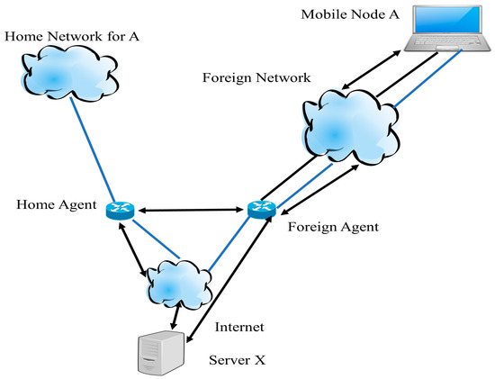
Figure 1.
Operation of mobile IP.
Step 2. When the IP datagram reaches the home network, the home agent receives the packet and encapsulates the CoA for mobile node A and re-transmits it. Due to the various destination IP addresses, the use of an outer IP datagram is called known as ‘tunneling’.
Step 3. When a packet reaches the foreign agent, it removes the IP header and encapsulates the original IP datagram in a network-level Protocol Data Unit (PDU). After encapsulation, it sends the entire IP datagram to node A.
Step 4. When mobile node A wants or needs to send data to server X, it uses its static IP address.
Step 5. When mobile node A sends data towards server X, it directly reaches server X using its static IP address. There are three steps to perform a mobile IP operation; it performs three tasks. The first task is discovering, which means the mobile node finds home agents and foreign agents. Mobile nodes use the registration process to inform their home agent about the CoA. Finally, the purpose of tunneling is to forward the IP datagram from the home address to the CoA [4,5].
The concept of the Virtual IP address (VIP) layer was introduced by the Victor Company of Japan (JVC) in 2003. According to the company, seamless communication between optical and Radio-Frequency (RF) wireless Local Area Networks (LAN) is possible if we create one intermediate virtual layer called the VIP layer between two network interface cards (NIC). To prove their concept, they perform one experiment. The client machine creates an Internet Protocol (IP) tunnel between the devices with the relay server’s destination address. There will be two tunnels between the client and the relay server. The relay server is further connected to the main server. The routing table of the router controls the whole complete situation and determines who can switch between two tunnel devices. With this simple method, seamless communication between two different NICs is assured [6]. More information material about the VIP layer and its benefits is available in [6]. As mentioned above, two different NICs use two different IP addresses. The problem in the Windows Operating System (OS), during the shifting of the connection between two IP sessions, is that the connection will be dropped [7,8,9].
Network nodes with a wireless interface and wired interface must have two different IP addresses if both are working simultaneously; otherwise, there will be a conflict of IP addresses. During handover or shifting the user from a wired link to a wireless link or wireless to a wired link, the current IP address will be changed. When the IP changes, its session and address are changed and lost. It will connect to the DHCP to obtain a new IP and start a new session. The whole process will take at least 30 s even using the Windows Bridge function. A delay of 30 s means a break in communication. To overcome this problem, the new concept of a virtual miniport or virtual port is introduced. In this method, when a user of one domain has a wired connection, removes its wired connection, and enters the second domain, its communication will not break. Figure 2 illustrates an example of this technique.
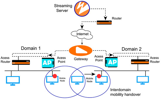
Figure 2.
Virtual miniport/virtual driver.
In this example, a mobile node moves from one domain to a second domain and uses 802.11b and 802.3 access technology. It creates one virtual miniport or driver that communicates with the wireless and wired NIC simultaneously. To provide the handover procedure, we used the Windows OS Network Driver Interface Specification (NDIS), as shown in Figure 3. Two models are presented; the first model communicates with the network card and keeps a record of ongoing and incoming traffic.
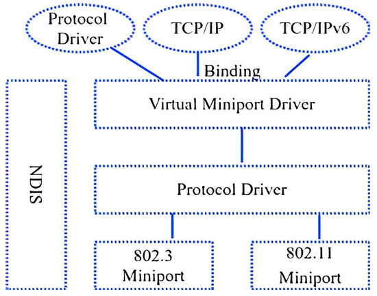
Figure 3.
Network driver interface specification.
The interface manager lies between the legacy protocol driver and the lower network card driver. The purpose is to use an intermediate protocol driver to support the virtual network port and multiplexing of 802.11b and 802.3. When a virtual miniport is created, a single IP address will be assigned to that port. In the case of network failure, the IP address will be the same, and there will be no connection loss. According to [10], during the handover process, the session will be lost. Therefore, to overcome this problem, almost the same concept is used with the MIH function. In this method, an intermediate driver is present between the protocol driver and the actual miniport driver. The intermediate driver generates a virtual protocol driver on the bottom and a virtual miniport driver on top.
In this model, there is a concept of the mobile address and fixed address. A fixed address is assigned to the primary and secondary links in the first model, but a mobile address is only assigned to the primary link. In the case of failure, the mobile address is assigned to the secondary link. When the mobile address is shifted, there is no loss of connection, and the application runs smoothly. In the second model, there are two computing devices, and they used different subnets.
When we talk about wired and wireless links at the same device, that means that, in the same computing or network device, there should be at least two NICs. Many vendors in the market are making such computing devices, mainly with the name “Blade server”. One example is the Dell Power Edge Server which comes with a dual NIC and dual power supply. The solution mentioned above is purely for wired computing and network devices, but the same method is used for wireless and wired solutions. Here, we discuss the different methods of network availability in a wired and wireless environment. These methods are sometimes used for the best roaming purpose or sometimes for resilience purposes. Hence, two methods and their problems are discussed. After a deep study of their problems, we suggested our proposed model and modification to the existing network topology, such as mesh networks and sensor networks, due to their route discovery and maintenance nature. Recent advancement in research at the network layer comes up with ample routing protocols to reduce the overhead of message control and reduce the end-to-end hop count and minimum energy consumption of wireless LAN networks. The term handover terminology is mainly used in cellular networks. This is a process of ongoing transfer of one voice or data session from one channel/backbone to another channel/backbone with the interruption of services. If handover occurs in the same type of network, then it is called homogeneous (horizontal).
In this paper, we propose a Versatile Resilience Ring protocol (VRPR)-based network model and provide the detailed simulation results. Further, the paper is organized as follows: Section 2 discusses related work and the pros and cons of the existing wired and wireless networks. Section 3 briefly explains the proposed Enhanced VRPR protocol model and its working mechanism, such as the packet drop percentage. Section 4 presents the simulation results, and finally, Section 5 concludes this paper.
Problem Statement and Contribution
To the best of our knowledge, as can be observed from the literature, the existing methods only cover the network performance in terms of packet loss and data center protection. However, a substantial amount of work is missing, e.g., the core reasons for packet loss, collision, and performance degradation. Furthermore, opportunistic and dynamic spectrum access in Core Route CR-TCP introduces results in the dropping of packets because of node mobility, spectrum mobility, and network congestion. As a result, the congestion window variation has a direct impact on the throughput and performance of CR-TCP.
To address these problems as mentioned above, our main contribution can be summarized as follows: the existing VRPR model works only on Layer 2, while our proposed model works on both Layer 2 and Layer 3 protocols. In addition, we address the delay and packet loss with the help of different scenarios, and provide maximum bandwidth to the active session, which has not been mentioned or implemented in the literature.
2. Related Work
As the name implies, Wireless Wide-Area Networks (WWANs) are used to cover outdoor networks. These networks are used to provide public Internet access systems or connect different branches of the deployed 2.4 GHz band, which can also be used by stand-alone systems when associated with photo-voltaic solar panels or wind systems. The WWAN uses protocols such as the Global System for Mobile Communications (GSM), General Packet Radio Service (GPRS), 3G, High-Speed Downlink Access (HSPDA), and Resilient Packet Ring (RPR). The RPR is the new ring topology that is currently being standardized by IEEE 802.17. RPR is mainly used in Metropolitan Area Networks (MAN) and WAN. The most crucial feature of RPR is its resilience. It can send data even if a link fails. Due to this feature, the popularity of RPR is increasing. MAN or WAN service providers are often based on the Synchronous Optical Network (SONET) or Synchronous Digital Hierarchy (SDH), which are similar to each other [10].
Commonly, the SONET uses a dual-ring configuration in which one of the two rings is set as a primary ring, and the other as a secondary ring. When the primary ring fails to send a frame, the secondary ring is used to send the frame, maintaining network connectivity, and providing an advantage over other networks. RPR can bridge over the other networks of IEEE 802. RPR uses a MAC protocol for gaining access to a shared ring communication medium. The stations or nodes on RPR use a MAC protocol for gaining access to a ring communication medium. The station decides which of the two counter-rotating rings would carry the frame to its destination station. The destination is identified by the address written on the frame header; if the address matches, the station would start to receive the frame; if not, the frame is passed to the next station. Suppose the given address does not match any station on the medium. In that case, the ring continues to rotate over the medium, making it busy, and other stations cannot send data. To overcome this problem, RPR implements Time To Live (TTL) on the frame, which means that it is deleted if no station receives the frame, to make the ring available for other stations. Every station on the medium consists of a buffer called a transit queue, in which the station that is transmitting the frame can be temporarily stored.
In combination with a wireless and wired network, many protocols and techniques provide network availability [11]. In addition, first, it prepares an address list of connected devices on the subnet. When the list is prepared, it sends test messages to all connected devices, and when the match is found, it re-establishes the link. This method is purely for a wired base network and involves a physical connection with all computing devices. We are not sure how it performs on a large-scale network. The algorithm tests all the devices one by one. Suppose one machine fails to respond; then, it tries to connect with the second device. Communication devices (PC, LAN switches, routers, wireless LAN, etc.) communicate with each other through the MAC address and Internet Protocol (IP) address. The MAC address is built on the NIC of each device, but the IP address is configured manually or by some server Dynamic Host Configuration Protocol (DHCP), and Bootstrap Protocol (BOOTP). In this model, Ethernet cards work on the physical layer, the switch works on the data link layer, and the router works on the network layer [12].
In contrast, TELNET and the File Transfer Protocol (FTP) work on the application layer that controls the session transport layer. The primary function of the router is to connect different LANs, learn available routes, select the best router, and maintain routes. Routers use different protocols to perform these functions, such as Open Shortest Path First (OSPF), Routing Information Protocol (RIP), etc. If some physical layer device fails, it cannot be detected by the upper layer of communication until the device tries to communicate. The main problems are (1) switching at the Ethernet level and (2) failure to connect any computing device via the IP address. When there is a hardware failure, there should be no interception on the application layer. When a link is down, it shifts to another link in the normal methods, but this shifting connection between devices may get lost, and the application cannot perform the job normally.
In another method [13], the central connectivity is the same, but two computing devices are used, and these devices are connected directly to each other, with central processing and a control software. Two routers are also used in this model, connected with the hubs. The whole procedure is described in a flow chart in which there are two primary states, a locked state, a normal state, and a failed state, which is used when the primary link is down. In this procedure, the computing device first makes a list of the available network nodes and uses a search algorithm. The system uses three different types of methods such as the Internet Control Message Protocol (ICMP) to ping to check the connection. The second method is the Address Resolution Protocol (ARP) which is mostly used in the LAN. The third one is the access port of the TCP or UDP. When the existing TCP protocol is used in wireless mesh networks, it reduces the congestion window size to half whenever the acknowledgment has not been received from the destination.
In [14], they propose that, in OTM, devices (STA) and Access Points (APs) can be traced from other packets such as CTS, ATS, and ACKs apart from beacons and frames. They performed a case study of monitor-mode packet capturing in an on-the-move and outdoor setup. Maintaining Quality of Service (QoS) is also a challenging task in MANET. In this work, they explored the RFDQ with a different perspective and tried it out with a multipath routing protocol under the non-attack environment. The mobile ad hoc network (MANET) diverges from the conventional wireless Internet infrastructure. MANETs are deployed in an environment that has no pre-existing infrastructure along with the irregular movement of nodes. They introduced a new routing protocol named the Velocity Constrained Multipath Routing Protocol (VC-AOMDV).
2.1. Route Failure and Spectrum Mobility
In this subsection, we discuss various types of route failures due to different handovers. The appearance of a Mobile Node (MN) in a wireless active channel or node mobility usually results in spectrum mobility. This spectrum mobility is available to various non-interfering channels inside the same spectrum band (intra-spectrum switching) or another type of spectrum band (inter-spectrum switching).
- WN Co-ordinate Message Update = True; //control channel
- Neighbor discovery (Channel + Route) = True;
- Case 1. If (Route Failure = WN Node Mobility)
- Step 1 : if (TTL < Local Channel-route Re-construction Time) Local Channel-route
- Re-construction= True; Next hop= route + new channel selection; Control channel
- Spectrum mobility= True;
- Else
- Step 2: Local Channel-route Re-construction = False;
- Globel re-route = True; New route = RREQ + RREP (Path +Channel) Control Channel
- Spectrum mobility = True
- Case 2. If (RouteFailure == MN Appearances) CR current channel allocate = False;
- If (Spare channel-path for next hop WN == True) Re-route = False; // Use spare
- Channel-path to next hop Spectrum mobility = True;
- If (spare channel-path for next hop WN == False) if (TTL < Local channel-route
- Re-construction time) go to step 1 else go to step 2.
Different types of Layers 2 handover delay factors are depicted in Table 1. There are two main types: mobile IP and protocols for micro-mobility support. In a network-layer handover, while moving from one Access Point (AP) to another AP, the IP address of the MN is changed [14,15,16]. This happens due to the mobile IP technique. Mobile IP is used for IPv4 (RFC 3344) and IPv6 (RFC 5944). In mobile IP, it uses two IP addresses: the home address and care-of address. When one MN moves from its home node to another node, it has one tunnel between the MN and the home link. In micro-mobility support, there are two types of methods. The first one is tunnel-based, and the second is routing-based. First, for the tunnel-based Hierarchical Mobile IP (HMIP), the Intra-Domain Mobility Management Protocol (IDMP) proposes a packet redirect technique inside a domain using a hierarchical mobile agent. Secondly, the routing-based Cellular IP (CIP) and Handoff-Aware Wireless Access Internet Infrastructure (HAWAII) use cross-layer techniques to generate paths to mobile nodes moving among access points. Table 2 shows the delay of handover.

Table 1.
Layer 2 handover delay [15].
Table 2.
Layer 3 handover delay [15].
This technology focuses on 3GPP, 802.21, UMA, and IMS. The essential method is IEEE 802.21, which is called MIH; its functionality is now widely adopted in different applications [9]. We will discuss this technology in detail in the next section. If the handover occurs in a different network, then it is called a heterogeneous (vertical) handover. Vertical handover is closer to our topic. In this process, one cell transfers its session to another network. It may be a wireless or wired network. There are different types of handovers; e.g., in a link-layer handover (802.11 and 802.11r), the MN moves from one AP to another AP in the same subnet. The IP address remains the same, so the outer AP does not know about this change, and communication goes in the link-layer protocol. In a physical handover, there are two types: the first one is hard, and the second one is soft. In a hard handover, first, the connection is broken with the AP, and then a new connection is established with the second AP. This is called “break before make” technology. In a soft handover, connections with both APs are established. This is called “make before break” technology.
2.2. Media-Independent Handover (MIH)
MIH is a standard which is developed by IEEE 802.21. [17] This standard supports users in moving their IP session from one layer to access the technology of another, as depicted in Figure 4. With the advancement in mobile technology, when a user moves from one area to another frequency area, the IP address changes. Due to the change in the IP address, the session is lost. This limitation is not only for mobile users, but also for the wired user. IEEE introduced the MIH standard to support the seamless handover between two different access technologies. It can be a wired or wireless handover. MIH works on Layer 2, but it also supports the upper layers. MIH has some outstanding features, as it helps in selection. It helps to continue the current session, and it is an open interface for link-state event reporting, intersystem information services, and handover control. MIH provides the architecture of handover for heterogeneous networks. It also helps with decisions about the handover and provides network information and commands. It also supports station- and network-initiated handover. However, it cannot define handover policies, network selection procedures, execute the handover, or the detection of the network [9]. Figure 5 reveals the traffic flow view of the VRPR-based network design.
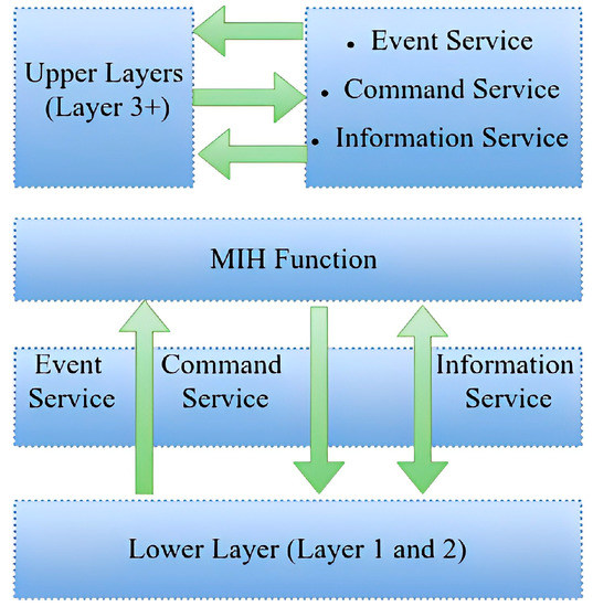
Figure 4.
Media-Independent Handover, MIH [17].
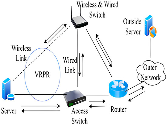
Figure 5.
Traffic flow diagram of VRPR-based network model.
There are three services of MIH: (1) event services, which provide triggers such as link up, down, or the availability of a new link, (2) command services, such as a switch, and the configuration of a link and initiating of the handover, and (3) information services, which provide information about the network, the IP version of the network, and the operators. All of these services are available through Service Access Points (SAPs). We also name these services Media-Independent Event Services (MIES), Media-Independent Command Services, Media-Independent Information Services (MIIS), and Media-Independent Handover Function (MIHF). We can use MIH in the handover between wired and wireless networks. We can even set different threshold values.
3. Proposed Model
The working of VRPR is straightforward. We aim to propose an Enhanced-VRPR-based network model that provides seamless communication and communication without interruption. Figure 6 shows the working mechanism of outgoing packets.

Figure 6.
Scenario B [15].
In existing wired networks, route failures occur mostly because of network congestion at stationary routers. Routing causes different route failures in wireless mesh networks because of handover delay and link failure overhead, except for buffer overflow. During the end-to-end application transmission in wireless mesh networks, Figure 2 explains different types of failure scenarios. This paper proposes a new model to identify the cause of the route failure, whether it is due to client mobility (handover), due to link breakage (channel degradation), or due to buffer overflow. We present detailed simulations using OMNeT++ to analyze the performance of our proposed scheme. A mobile node appearing in the wireless node active channel or node mobility sometimes creates spectrum mobility to various non-interfering channels. This spectrum mobility, inside the same spectrum band or another spectrum band, explains different route failures because of different handovers in the 902 MHz control channel spectrum handoff scheme.
3.1. VRPR Packet Flow from Server to Gateway
When a packet is generated in the server, the server also generates its copies. One copy is sent out via the LAN NIC, and another copy is sent out through the WLAN NIC. The LAN packet travels on the wire until it reaches the LAN switch. The switch always checks the status of the switch-to-router link. If the link, from the switch to the router is down, then the packet is diverted towards the access point. The access point sends this packet towards the gateway router. The same process is replicated with the WLAN NIC when a packet enters a network or a packet acknowledgment comes through the Gateway (GW) router. The link breakage of the next hope can be identified using CTS, even after sending the maximum number of RTS retransmission attempts at the MAC layer. Using a congestion notification algorithm, a buffer overflow can be identified during the acknowledgment message. Another IETF standard named the Explicit Congestion Notification (ECN) [18] is mostly adopted to inform the destination TCP protocol if there is any congestion in the network. The packet loss is the main reason for congestion in the TCP network. Upon successfully negotiating the congestion notification, ECN-aware mesh routers mark the IP header as opposed to dropping packets. If the route failure is beyond the first two techniques, then it is known as a handover link failure. It is very crucial to determine the Round Trip Time (RTT) [19,20,21] to further improve the efficiency of routing protocols in mobile-based wired and wireless networks.
3.2. VRPR Packet Flow When a Packet Enters a GW Router
When a packet is received, a router has to check whether it is an acknowledgment or a new packet. If it is a new packet, then it is sent to the high-priority link. If this is an acknowledgment, then it is sent to the same link from whence it came [18]. When going towards the internal server, a packet reaches the WLAN Access Point (AP), and if the AP finds that the link from the AP to the server is down, it will route traffic towards the AP to the LAN switch. The LAN switch will send the traffic towards the server. We designed the logical diagram VRPR (shown in Figure 6), which is a new concept proposed and tested for the LAN only. In the future, we can propose the same a network model for the MAN and WAN.
We have tested VRPR in the prior monitoring of the link model. This means that, when a packet enters a switch, the switch checks the status of the outgoing link. If the link is available, it sends a packet on the main link; otherwise, it sends the packet on an alternative link. If the switch is sending a packet on the main link and the transmission of the packet link is broken, there will be a packet loss. This is an infrequent possibility; however, we plan to develop a solution for this limitation in the future. We have used Layer 3 switches. This is a wired switch having optical ports and copper ports. The access switch sends a ‘Hello’ packet to its connecting devices and checks the link status when the packet reaches the switch. It is the responsibility of the access switch to check the status of the link. If the link is down, then the switch will send this packet towards the secondary link (in our case, the switch to the access point link is the secondary or alternative link). The function of the access points is the same as that of the access switch. This access point should support 802.11g for high-speed data transfer. An access point has wired ports. This access point is a wired and wireless switch.
The role of the gateway router is significant in our proposed network model. We have suggested adding some more intelligence to a gateway router. When the packet reaches the switch from the wired link, it will first send it to the gateway router, which keeps traces of its path.
Our proposed VRPR-based network model is a complete suite. It is implemented in a server, switch, access point, and gateway router. The internal network consists of two rings. The first ring consists of a server, access point, and switch. The second ring consists of an access point, switch, and router. We have selected only one server to understand the working of our model better. The server is connected to one Layer 3 (L3) access switch via a fiber cable. The server is also connected to an access point via a wireless link of 802.11g. The access switch and access point are connected to a fiber cable and these two devices are connected to the gateway router. The gateway router is connected to the Internet Service Provider (ISP) cloud. We also include one external server to complete the network. The scope of VRPR is only within one data center. We propose some advanced features in the server, access switch, access point, and gateway router.
Servers can either be blade servers or regular servers, but in our proposed network model, the primary purpose is to generate a packet and to generate a duplicate of each packet. After duplicating a packet, the server sends one copy to the wireless network card and sends another copy to the wired network card. In addition, we propose optical ports in servers. When a wireless packet reaches the GW router, the GW router will compare it with the traces of the path of the wired packet. If the same packet is received, then the router will discard the wireless packet. If the router received only packets from a wireless link, it would assume that the wired link is down and it sends out the wireless packets. When an acknowledgment arrives at the router from the outer network router, the router again checks the traces of the path and sends this acknowledgment towards that link from whence it comes.
In our proposed network model, we have made some scenarios. To check the delay in the complete LAN network, we discuss these scenarios in detail as follows:
- Scenario A:
In this scenario, all the links are functional, and each device can communicate without any interruption. In the subsequent two scenarios, we introduce wired and wireless link failures and explain how the network handles the situation in the case of link failure.
- Scenario B:
In this scenario, the link from the server to the access switch is down. The traffic from the server is sent only via the wireless link and it has been reached at the access point. The access point will send traffic towards the GW router. Here, the gateway router will check: if the traffic is coming from a wireless link, then the GW router will send it to the external network. In Scenario C, the traffic flow is from the external network to the internal server. If the packet reaches the switch and the link from the switch to the server is down, traffic will be routed towards the access point, and an access point will send the traffic to the server. Figure 7 illustrates the logical diagram of scenario B.
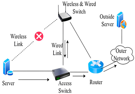
Figure 7.
Scenario C [11].
- Scenario C:
In this scenario, we assume that the wireless links are down from the server to the access point, and packets go outside of the network. The delay factor becomes very important when running time-sensitive applications such as voice, video, etc. To check the delay in the whole LAN network, we have made different scenarios which are discussed below. We have tested our proposed model in two different media, namely, wired and wireless media. The whole traffic goes from the wired link to the access switch and from the access switch to the router. As depicted in Figure 8, the router will keep traces of the path of the traffic and will forward the traffic to the outer network.
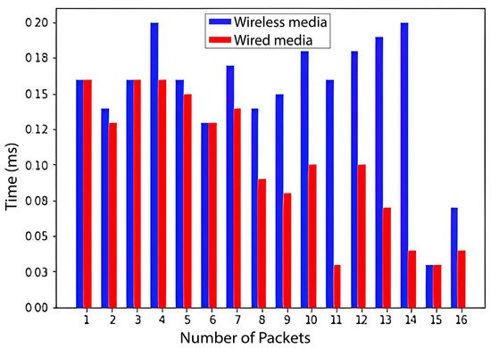
Figure 8.
Packets sent from/to the server.
4. Simulation Results
We performed the experiments using OMNeT++ [21]. This simulator is modular, and it is used for modeling wireless and wired communication networks, multiprocessors, microprocessors, and other various types of parallel and distributed computing systems. It is developed using the C++ language, and it is composed of different basic modules that communicate with each other. Furthermore, these basic modules are used to generate large modules [22]. To start our simulation, we consider the following assumption.
To perform the simulation in OMNeT++, we should understand the C++ language because the commands and coding are very similar to C++. To start work in the simulator, we make a diagram according to the scenario described in the above section. Obtaining results from the simulation software is a bit risky and complicated. Therefore, we have to depend primarily upon the simulation software. We evaluated the performance of our proposed model mainly on three parameters: the delay, packet loss, and comparison between wired and wireless networks.
4.1. Delay
The packet delay in the IP network is significant because it affects the overall performance of the network. When we tested our proposed model, it is observed that the wired medium is faster than the wireless one, but wireless is faster than wired in most cases. The overall observation is that wired media is faster and more reliable than wireless media. In Figure 9, the blue bar shows the time taken by different packets from the server to the gateway through wireless media. The horizontal line shows the number of packets, and the vertical line shows the time taken by a packet. This graph shows that the maximum time taken by any packet is 200 ms. The red bar shows packets that are transmitted from the server to the gateway through wired media. In this case, the maximum time taken by any packet is less than 200 ms, and the overall time is also less than the wireless medium.
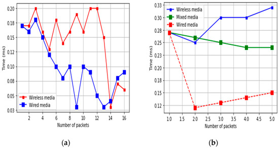
Figure 9.
Comparison between wireless and wired media: (a) wired/wireless media, and (b) wired/wireless and mixed media.
We also experimented using mixed media. Figure 10a shows the packet movement from the gateway to the server through mixed media.
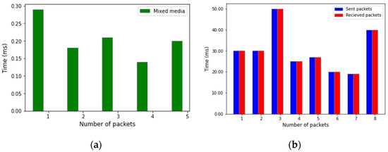
Figure 10.
Comparison between packets sent/received and mixed media: (a) mixed media, and (b) sent/received packets.
4.2. Packet Loss
Packet loss in a network is a very critical problem. The VRPR-based network model is designed to minimize packet loss. It provides complete redundancy in wired and wireless media. To test our proposed model, we have run the simulation eight times and sent different packets to the network to check the packet loss. During the test, we observe no packet loss, which proves that our proposed model is efficient. Figure 10b shows the obtained results. In these experiments, we considered only the LAN. The blue color shows packets sent by the central server. The red color represents packets received by the central server. We varied the number of packets sent from 17 to 50. In all cases, the number of received packets is the same as the number of sent packets.
4.3. Comparison between Wired and Wireless Media
The role of wired and wireless media is well-established. A wired medium can support more bandwidth than a wireless medium [23]. A wireless medium is more flexible than a wired medium. To check wired and wireless media performance, we have collected the packet transmission time of wired and wireless media. We observed that wired media is faster than wireless. The main reason is wireless delay. Figure 10 shows the obtained results. We experimented with different simulation parameters. These parameters have been depicted in Table 3.
Table 3.
Simulation parameter: wireless and wired.
The red color line shows the transmission time in the wireless link. The blue color line shows the transmission time in the wired link. The horizontal line shows the number of packets, and the vertical line shows the time taken by the packet during transmission. In Figure 10a,b, we have also included mixed media, which include both wired and wireless media. This mixed media is similar to wireless media but shows a little bit better performance.
As a comparison of our work and results with other work, in [14,24,25], a case study on the monitor mode passive capturing of WLAN packets in an on-the-move setup, analyzing QoS with multipath routing using real flows dynamic queue (RFDQ) in manet and limiting route request flooding using velocity constraint in multipath routing protocol has been discussed in detail.
5. Conclusions
Our objective, in this work, is to propose a VRPR-based network model, which provides reliable communication between network devices within the LAN. We developed the model and simulated it in OMENeT++. The model is a secure and almost error-less communication model with 0% packet loss within the LAN. We have tested the difference between wired and wireless media by measuring their transmission time. We have found that wired media is faster than wireless, especially fiber. VRPR is implemented in every Network Element (NE) of the LAN. VPRP provides a nominal convergence time, which results in no blockage of traffic. We have found some delay if the main wired link is broken and traffic flows over the wireless link, and this is due to the limitation of the wireless link delay. However, the main objective of seamless communication has been achieved.
6. Limitation and Future Work
When a packet is received, a router checks whether it is an acknowledgment or a new packet. If it is a new packet, then it is sent to the high-priority link. If this is an acknowledgment, then it is sent to the same link from whence it came. When going towards the internal server, a packet reaches the WLAN Access Point (AP), and if the AP finds that the link from the AP to the server is down, it will route traffic towards the AP to the LAN switch. The LAN switch will send the traffic towards the server. We designed the logical diagram VRPR (shown in Figure 6), which is a new concept proposed and tested for the LAN only. In the future, we can propose a network model for the MAN and WAN.
We have tested VRPR in the prior monitoring of the link model. This means that when a packet enters a switch, the switch checks the status of the outgoing link. If the link is available, it sends a packet on the main link; otherwise, it sends the packet on an alternative link. If the switch is sending a packet on the main link and the transmission of the packet link is broken, there will be a packet loss. This is an infrequent possibility; however, we plan to develop a solution for this limitation in the future.
Author Contributions
Conceptualization, T.M.; data curation, S.K.; formal analysis, T.M., F.A., A.A. and J.A.; investigation, T.M. and A.H.; methodology, T.M.; project administration, F.A. and J.A.; resources, A.H.; software, A.A.; supervision, F.A. and J.A.; visualization, F.A.; writing—original draft, T.M., A.A. and S.K.; writing—review and editing, J.A., T.M. and F.A.; proofreading and writing the paper script in overleaf, T.M. All authors have read and agreed to the published version of the manuscript.
Funding
This work was supported partially by the BK21 FOUR program of the National Research Foundation of Korea funded by the Ministry of Education (NRF5199991514504) and by the MSIT (Ministry of Science and ICT), Korea, under the ITRC (Information Technology Research Center) support program (IITP-2023-2018-0-01431) supervised by the IITP (Institute for Information & Communications Technology Planning & Evaluation).
Institutional Review Board Statement
Not applicable.
Informed Consent Statement
Not applicable.
Data Availability Statement
Not applicable.
Conflicts of Interest
The authors declare no conflict of interest.
References
- Alharbi, F. Adaptive predictive proportional controller for ieee 802.17. IEEE Access 2020, 8, 23082–23089. [Google Scholar] [CrossRef]
- Tahir, S. A Seamless Vertical Handover based on IEEE802.21 & IPv6 for Heterogeneous Wireless Network. In Proceedings of the 2018 3rd IEEE International Conference on Inventive Computation Technologies (ICICT), Coimbatore, India, 15–16 November 2018; pp. 23–29. [Google Scholar]
- Ranganathan, R.; Kambalapally, V.; Kannan, K. Modelling link failure in the presence of extended hidden terminals over multi-hop wireless ad hoc networks. SN Appl. Sci. 2020, 2, 383. [Google Scholar] [CrossRef]
- Guo, Y.; Li, Z.; Lv, R.; Yang, Z. Evaluating the impact of aggregation and RTS/CTS schemes on IEEE 802.11 based Linear Wireless Ad-Hoc Networks. Eng. Rep. 2022, 4, e12516. [Google Scholar] [CrossRef]
- Lee, S.B.; Hur, K.; Park, J.; Eom, D.S. A packet forwarding controller for mobile ip-based networks with packet buffering. IEEE Trans. Consum. Electron. 2009, 55, 1344–1350. [Google Scholar] [CrossRef]
- Jung, Y.; Agulto, R. Virtual IP-based Secure Gatekeeper System for Internet of Things. Sensors 2020, 21, 38. [Google Scholar] [CrossRef] [PubMed]
- Pandi, S.; Wunderlich, S.; Fitzek, F.H.P. Reliable low latency wireless mesh networks—From Myth to reality. In Proceedings of the 2018 15th IEEE Annual Consumer Communications & Networking Conference (CCNC), Las Vegas, NV, USA, 12–15 January 2018; pp. 1–2. [Google Scholar]
- Zhao, D.; Yan, Z.; Wang, M.; Zhang, P.; Song, B. Is 5G Handover Secure and Private? A Survey. IEEE Internet Things J. 2021, 8, 12855–12879. [Google Scholar] [CrossRef]
- Jain, R. IEEE 802.21 Media Independent Handover (MIH); Washington University in St. Louis: St. Louis, MO, USA, 2010. [Google Scholar]
- Mountaser, G.; Mahmoodi, T. An sdn-based experimental study of reliable and low latency ethernet-based fronthaul with mac-phy split. Future Internet 2021, 13, 170. [Google Scholar] [CrossRef]
- She, C.; Chen, Z.; Yang, C.; Quek, T.Q.S.; Li, Y.; Vucetic, B. Improving Network Availability of Ultra-Reliable and Low-Latency Communications with Multi-Connectivity. IEEE Trans. Commun. 2018, 66, 5482–5496. [Google Scholar] [CrossRef]
- Chao, I.-F.; Lee, C.-H. Awg-based wdm ring networks: High-performance and lowcost system designs. Comput. Netw. 2018, 145, 64–75. [Google Scholar] [CrossRef]
- Maksimovic, M.; Vujović, V.; Davidović, N.; Milošević, V.; Perišić, B. Raspberry pi as internet of things hardware: Performances and constraints. Des. Issues 2014, 3, 1–6. [Google Scholar]
- Verma, S.S.; Patel, R.B.; Kumar, A.; Vishwakarma, S. Analyzing QoS with Multipath Routing Using Real Flows Dynamic Queue (RFDQ) in Manet. J. Adv. Res. Dyn. Control Syst. 2020, 12, 5. [Google Scholar] [CrossRef] [PubMed]
- Iqbal, M.M.; Khiyal, M.S.H. Implementation of versatile resilience packet ring protocol (vrpr) in datacenter network. PONTE Int. J. Sci. Res. 2017, 73, 98–110. [Google Scholar]
- Guan, J.; Sharma, V.; You, I.; Atiquzzaman, M.; Imran, M. Extension of MIH for FPMIPv6 (EMIH-FPMIPv6) to support optimized heterogeneous handover. Future Gener. Comput. Syst. 2019, 97, 775–791. [Google Scholar] [CrossRef]
- Khattab, O.; Alani, O. The design and calculation of algorithm for optimizing vertical handover performance. In Proceedings of the 2014 9th International Symposium on Communication Systems, Networks & Digital Sign (CSNDSP), Manchester, UK, 23–25 July 2014; pp. 401–406. [Google Scholar] [CrossRef]
- Santhi, J.; Prabha, K. QOS aware vertical handover process in heterogeneous wireless network. Meas. Sens. 2023, 26, 100710. [Google Scholar] [CrossRef]
- Ye, J.; Li, L.; Chen, Z.; Chen, G.; Liu, S.; Huang, J.; Wang, J.; He, T. ECN-based shared bottleneck detection for multi-path TCP. Comput. Commun. 2022, 186, 90–101. [Google Scholar] [CrossRef]
- Tian, L.; Santi, S.; Seferagić, A.; Lan, J.; Famaey, J. Wi-Fi HaLow for the Internet of Things: An up-to-date survey on IEEE 802.11ah research. J. Netw. Comput. Appl. 2021, 182, 103036. [Google Scholar] [CrossRef]
- Li, J.; Zhou, S.; Giotsas, V. Performance Analysis of Multipath BGP. In Proceedings of the IEEE INFOCOM 2021—IEEE Conference on Computer Communications Workshops (INFOCOM WKSHPS), Vancouver, BC, Canada, 10–13 May 2021; pp. 1–6. [Google Scholar]
- Ahamed, A.; Vakilzadian, H. Impact of direction parameter in performance of modified aodv in vanet. J. Sens. Actuator Netw. 2020, 9, 40. [Google Scholar] [CrossRef]
- He, H.; Li, T.; Feng, L.; Ye, J. Frame transmission efficiency-based crosslayer congestion notification scheme in wireless adhoc networks. Sensors 2017, 17, 1637. [Google Scholar] [CrossRef] [PubMed]
- Prasad, A.; Verma, S.S.; Dahiya, P.; Kumar, A. A Case Study on the Monitor Mode Passive Capturing of WLAN Packets in an On-the-Move Setup. IEEE Access 2021, 9, 152408–152420. [Google Scholar] [CrossRef]
- Soni, R.; Dahiya, A.K.; Verma, S.S. Limiting Route Request Flooding Using Velocity Constraint in Multipath Routing Protocol. In Proceedings of First International Conference on Smart System, Innovations and Computing; Springer: Singapore, 2018. [Google Scholar]


Disclaimer/Publisher’s Note: The statements, opinions and data contained in all publications are solely those of the individual author(s) and contributor(s) and not of MDPI and/or the editor(s). MDPI and/or the editor(s) disclaim responsibility for any injury to people or property resulting from any ideas, methods, instructions or products referred to in the content. |
© 2023 by the authors. Licensee MDPI, Basel, Switzerland. This article is an open access article distributed under the terms and conditions of the Creative Commons Attribution (CC BY) license (https://creativecommons.org/licenses/by/4.0/).