Article

Theoretical Approach to Predicting the Diffusion Radius of Fracture Grouting in Soil–Rock Mixtures

1
School of Civil Engineering, Chongqing University, Chongqing 400045, China
2
National Joint Engineering Research Center of Geohazards Prevention in the Reservoir Areas, Chongqing University, Chongqing 400045, China
*
Author to whom correspondence should be addressed.
Appl. Sci. 2023, 13(8), 4730; https://doi.org/10.3390/app13084730
Submission received: 7 March 2023 / Revised: 2 April 2023 / Accepted: 6 April 2023 / Published: 9 April 2023
(This article belongs to the Special Issue Advances in Tunneling and Underground Engineering)

Abstract

:
Previously conducted studies have established that the soil–rock mixture in the Chongqing area has the characteristics of loose structure, poor stability, strong permeability, and so on. When building a tunnel in a soil–rock mixture stratum, it is necessary to reinforce the surface rock mass and surrounding rock by grouting to improve the safety of tunnel excavation. To study the diffusion mechanism of cement slurry (Bingham fluid) in soil–rock mixtures, based on the Bingham fluid flow equation and slurry diffusion model, the Bingham fluid fracture diffusion formula was derived, and field grouting tests and indoor model tests were carried out with soil–rock mixtures in the Chongqing area as the research object. The fracture grouting diffusion formula was verified and analyzed using the test data. The research results show that the theoretical calculation results of various working conditions are close to the actual test results (the error of indoor model test results is less than 3%, and the error of field test results is less than 5%). A Bingham fluid fracture diffusion formula has been developed that applies to various working conditions of fracture grouting of soil–rock mixtures and has a good prediction effect on the value of the fracture diffusion radius.

1. Introduction

The soil–rock mixture is an inhomogeneous loose geotechnical media system composed of a particular engineering scale, high-strength block, fine-grained soil, and void space with a certain stone content [1]. This type of soil–rock mixture has a loose structure, large void ratio, weak cementation ability, poor stability, and strong permeability, which often causes cavity deformation, uneven settlement, collapse, water seepage, and other problems when tunneling through deeply buried soil–rock mixture strata, bringing great difficulties to construction. Therefore, when the tunnel passes through a deeply buried soil–rock mixture, the tunnel surface geotechnical body and the surrounding rock need to be reinforced with grout to form a ring-shaped bearing arch around the perimeter of the tunnel to ensure the stability of the perimeter of the tunnel and the palm face and to improve the permeability of the surrounding rock tunnel.
In the design of rock and soil mass grouting parameters, the slurry diffusion radius should be determined first, according to the diffusion radius to determine the grouting hole row distance, hole spacing, single hole grouting amount, grouting pressure, and other parameters, so the determination of the diffusion radius is the key to the success of the grouting project. Grouting diffusion can be divided into fracture diffusion, permeation diffusion, and compression diffusion, among which fracture grouting is widely used in tunnels, mines, road foundations, soft ground, and embankment reinforcement. Conventional soil–rock mixtures have a stone content ranging from 20 to 50%, and their grouting reinforcement is often in the form of fracture grouting [2]. The basic principle of fracture grouting is that when a continuously increasing grouting pressure is applied in a weakly permeable foundation to cause hydraulic fracture of the soil, the pressure exerted by the slurry on the fracture surface will push the cracks to open rapidly and form grout cracks. The slurry veins extrude soil, and the skeleton effect of the slurry veins will reinforce the soil [3]. Due to the complexity of the process, the current research on the theory of fracture grouting lags far behind engineering practice. Moreover, research results on the diffusion mechanism of fracture grouting have only emerged in the 21st century.
Based on the statistics of domestic and foreign scholars, reference [4] took a particle size of 5 mm as the soil and stone boundary particle size of the soil–rock mixtures. Reference [5] established a flat plate fracture model with a power-law-type slurry and derived a new power-law fluid fracture grouting diffusion equation while giving a parameter determination method. Reference [6] used a model test of loess grouting to divide the process into three stages: primary, expansion and fracturing, and diffusion, and they simulated the process with PFC2D granular flow software. Reference [7] used a combination of FEM and VOF to simulate the fracture grouting process and studied the flow and diffusion law of the slurry. Reference [8] investigated the relationship between low-pressure permeation grouting and the starting pressure of fracture grouting based on engineering examples and proposed corresponding engineering empirical criteria. Reference [9] applied silica-sol material to simulate the grouting process, obtained an expression for the diffusion radius of the slurry within the fissure, and verified the correctness of the expression based on field measurement results. Sarris and Reference [10] investigated the main factors affecting the expansion of hydraulic fractures in continuous media soils through numerical simulations and experiments. Reference [11] proposed an analytical model for fracture grouting in sandy soils, simplified the fracture channels into pipe and flat plate modes, and described the fracture grouting process, the diffusion radius of the slurry, and the width of the slurry veins. Reference [12] studied fracture and fracture-permeation grouting in weathered granite soils in the Korean Peninsula. Theoretical equations were derived by studying the fracture pressure, fracture length, and thickness, and the effect of grouting pressure on the slurry percolation phenomenon was investigated. Reference [13] studied the diffusion characteristics of grout in soft clay and structured soil through experiments and numerical models. The numerical simulation of slurry diffusion in a single sand layer has been studied [14,15,16]. To improve the stability of the tunnel surrounding the rock, references [17,18] studied the diffusion radius of slurry in gravel and the compressive strength of the soil–rock mixtures under the influence of multiple factors through laboratory experiments. Reference [19] focused on verifying the radial Bingham flow of cementitious grout using a fracture model constructed from acrylic glass. A grout penetrability method based on explicit grout forehead pressure (EGFP) algorithm for joints and cracks in a rock mass was developed in [20]. The diffusion characteristics of slurry in fractured rock have also been well studied [21,22]. Reference [23] proposed that the flow pattern properties of cement grouts with different water–cement ratios could remain unchanged with time. The characteristics of cement grouting were studied [24,25]. Reference [26] presented a study on the use of chemical additives to optimize the performance of cement slurry, which significantly improves the quality of grouting. On the properties of cement materials, particular attention was given to the rheological characteristics, namely, the composite transportability while maintaining the specified strength characteristics [27]. To increase the strength characteristics of the created composite, fullerene-astarlene was used as a nanomodified additive [28]. Reference [29] investigated the cement-and-gravel mixture’s transportability (rheological characteristics). Activation treatment of composite components or adding some activating additive is one way to improve the quality of the cement-and-gravel mixture [30]. References [27,29,30] showed that using finely dispersed fractions in backfill improves the rheological properties of the cement-and-gravel composite and increases its transportation range and permeability. Reference [31] used “shallow anchor grouting + deep anchor cable grouting” in combination with a fracture grouting mechanism to reinforce the roadway. Reference [32] proposed a simulation method for the grouting process based on the 3D fracture network model, considering the flow–solid coupling effect. Reference [33] established an analytical model of grouting diffusion for a single rough fracture under constant pressure control based on Bingham fluid’s intentional equation. Some scholars have studied soil–rock mixtures’ strength parameters and cracking damage characteristics [34,35]. The shear modulus of the soil–rock mixtures gradually increased with the increase in rock regardless of temperature, and the increment rate of the shear modulus increased rapidly [36]. Reference [37] presented a random generation method of periodic mesostructures of soil–rock mixtures based on the random polygon. An automatic generation method of PFC, similar to a 2D numerical model of soil–rock mixture microstructure, based on digital image processing and experimental simulation were carried out with Matlab [38]. In terms of soil mechanical properties, changes in the degree of saturation can significantly affect the peak strength [39,40], elastic moduli [41], and Poisson ratio of soil.
In summary, most of the injected media involved in the existing research on the mechanism of fracture grouting are crushed stone, gravel, clay, or rock with a single and isotropic material composition. However, in practice, the injected media conditions may be a mixture of various materials, and research on the diffusion mechanism of fracture grouting based on composite geological conditions is limited. Research on the diffusion mechanism of fracture grouting is late in development, and there is still no unified identified formula for the diffusion radius of fracture grouting as a theoretical basis. Most of the existing research on the diffusion of fracture grouting is based on Newtonian slurries and power-law slurries, and there are fewer research results on the fracture diffusion mechanism of Bingham fluid. However, cement slurry, cement clay slurry, and composite cement slurry commonly used in grouting engineering with a water–cement ratio of 0.6~1.0 are all Bingham fluids [42]. It can be seen that the mechanism of fracture grouting diffusion of soil–rock mixture under the Bingham fluid is an urgent problem to be solved.
Analyzing the above, it can be noted that the diffusion radius of fracture grouting is a very topical issue. Therefore, the purpose of this study is to establish the diffusion formula of soil–rock mixture fracture grouting under a Bingham fluid; to achieve this, it is necessary to solve the following:
(1)
Derivation of the Bingham fluid flow equation.
(2)
Establishing the diffusion formula of soil–rock mixture fracture grouting under Bingham fluid.
(3)
Conducting field grouting tests and indoor model tests under different working conditions.
(4)
Adaptation verification of the fracture grouting diffusion equation using grout diffusion radius data from field grouting tests and indoor model tests.

2. Calculation Theory for Fracture Diffusion of Bingham Fluid

The mechanism of grouting diffusion in single materials such as gravel and clay has been studied by predecessors. In gravel, the slurry is often diffused in the form of permeation, while in clay, the slurry is often diffused in the form of fracture. Unlike these single media, the mechanical properties and permeability of the soil–rock mixtures are affected by factors such as stone content, and the physical and mechanical properties of the soil–rock mixtures are between those of soil and stone. Therefore, the slurry diffusion form may be changed, affecting the diffusion radius, an essential parameter in grouting engineering. In this section, the fracture diffusion formula of a Bingham fluid is derived theoretically.

2.1. Bingham Fluid Flow Equation

The shear rate of the Bingham fluid is not proportional to the shear stress, and the slurry starts to flow only when the shear stress exceeds the yield value τ ο . The rheological equation of the slurry is shown in Equation (1).
τ = τ ο + η p d v d r            
The crack flow equation will be derived from the Bingham fluid rheology equation. Figure 1 shows the flow of the Bingham fluid in a crack.
Take a quadrangular prism with width b = 1 in the crack, and crack width δ . Take a fluid column with the central axis of the tube as the axis of symmetry in the quadrangular prism; the length of the fluid column is d l , the height is 2 r , the width is b = 1 , and the side of the fluid column is subject to uniformly distributed shear stress τ . According to the force balance relationship of the fluid column (without considering gravity), we can obtain the following:
τ = r d p d l
That is, the shear stress τ on the fluid column surface is proportional to the product of the fluid column height r and the pressure gradient ( d p d l ), but the sign is the opposite. Substituting Equation (2) into Equation (1), we obtain the following:
d v d r = r d p η p d l τ 0 η p = 1 η p τ τ ο  
According to Equation (3), it is found that the magnitude of the shear stress varies linearly with height; the further away from the center, the greater the shear stress, while at the centerline, the shear stress is minimal. When the shear stress is τ = r d p d l τ ο , the velocity gradient is 0; that is, the velocity does not change with r , indicating that the shear stress is 0 within this range. There is a height r m in the quadrangular prism such that the fluid in the range 0 r r m is relatively stationary, and its velocity is denoted as the velocity v m at the height ( r m ). When the fluid is in the range r m r r , the fluid is moving with respect to the adjacent fluid. Therefore, the fluid as a whole exhibits piston motion, which is divided into the shear zone ( r m r r ) and piston zone ( 0 r r m ).
When r = r m , τ = τ 0 , according to Equation (3):
r m = τ 0 d l d p      
When boundary condition r = δ 2 is taken into account, velocity v δ 2 = 0 . By separating the variables in Equation (3) and integrating both sides’ yields, we can obtain the following:
v = d p 8 η p d l δ 2 4 r 2 + τ 0 ( δ 2 r ) 2 η p ,       r m r r
When ( 0 r r m ), it follows that:
v = v m = d p 8 η p d l δ 2 4 r m 2 + τ 0 δ 2 r m 2 η p
The flow rate ( q ) of the slurry in the fluid column can be found by integrating the following:
q = 2 0 δ 2 v r b d r + 2 b v m r m
Substituting Equations (5) and (6) into Equation (7) gives:
q = 2 b η p d p 8 d l 8 r m 3 δ 3 3 τ 0 δ 2 + 4 r m 2 8    
The average flow velocity in the longitudinal section is   v ¯
v ¯ = q δ b = 2 η p δ d p 8 d l 8 r m 3 δ 3 3 τ 0 δ 2 + 4 r m 2 8
Equations (8) and (9) are the crack flow equations of a Bingham fluid.
When the shear stress is insufficient to produce a fluid flow rate, the quadrangular prism’s flow rate is 0. The d p 8 d l 8 r m 3 δ 3 3 τ 0 δ 2 + 4 r m 2 8 part of Equation (8) is 0, which gives:
d p d l = 3 τ 0 δ 2 + 4 r m 2 8 r m 3 δ 3    
That is, 3 τ 0 δ 2 + 4 r m 2 8 r m 3 δ 3 is the initiation pressure gradient value of the Bingham fluid in the quadrangular prism, and the flow rate is generated only when the pressure gradient exceeds this value.

2.2. Bingham Fluid Fracture Diffusion Equation

The theoretical derivation in this paper is mainly based on the engineering geological and hydrogeological conditions of the relying project (Wangjiacheng Station to Shengjiabao Station of Chongqing Railway Line 4 Phase II Project), without considering the influence of groundwater. Since the relying project is located in Chongqing, China, which is a mountainous city with large topographic relief and low groundwater level, the water table line is generally located below the bottom of the tunnel of the relying project, and the groundwater pressure is low during the grouting process, the coupling of mechanical and hydraulic effects is not considered.
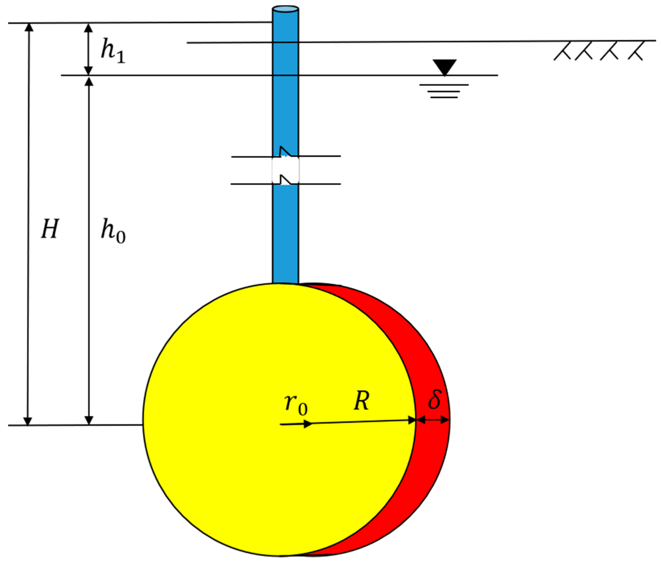
It is assumed that the slurry diffuses radially in the crack surface of the soil–rock mixtures with the exit of the grouting pipe as the center. The soil–rock mixtures are considered to be mixed evenly. The slurry is injected into the soil–rock mixtures from the bottom of the grouting pipe. The theoretical model of slurry diffusion is shown in Figure 2.
The slurry diffusion form is planar radiative diffusion, which can be described as a “point source planar radiative diffusion model”. The fluid cross-section is not affected by the void ratio, so the amount of fracture grouting is:
Q = π R 2 δ = v ¯ A t ,   A = 2 π r δ
h 0 is the groundwater hydraulic head above the grouting pipe, h 1 is the grouting pressure, and H is the sum of the groundwater hydraulic head and grouting pressure, namely, H = h 0 + h 1 ; H is equal to h 1 when h 1 is much larger than h 0 . The crack width is δ , the grouting time is t , and the grouting pipe radius is r 0 .
For a Bingham fluid, substituting Equation (9) into Equation (11) gives:
v ¯ = Q A t = 2 η p δ d p 8 d l 8 r m 3 δ 3 3 τ 0 δ 2 + 4 r m 2 8
For Equation (12), we separate the variables and consider the boundary conditions: let p k be the initiation fracture pressure of soil when the grouting pressure p r reaches the initiation fracture pressure p k , at which point the diffusion radius r = r 0 ; after t time, when the diffusion radius reaches the maximum value ( R ) , the grouting pressure is p 0 , then we have:
p 0 p k = 12 η p δ R 2 8 r m 3 δ 3 t ln R r 0 + 3 τ 0 δ 2 + 4 r m 2 8 r m 3 δ 3 R r 0
Since r 0 is much smaller than R , Equation (13) can be simplified, which in turn, gives the relationship between the grouting pressure ( p 0 ) and the diffusion radius ( R ) and grouting time ( t ) as:
p 0 = p k + 12 η p δ R 2 8 r m 3 δ 3 t ln R r 0 + 3 τ 0 δ 2 + 4 r m 2 8 r m 3 δ 3 R
There are many unknown quantities in Equation (14), among which the radius of the grouting pipe r 0 is known, the grouting time t can be controlled according to the actual engineering situation and field experience, while the indoor grouting test in this paper records the grouting time through a timer. In addition, the static shear force τ 0 and plastic viscosity ( η p ) . of the slurry are measured using a rotating viscometer, and the rotational speed of the viscometer is changed to measure the shear stress readings at different shear rates, which are brought into the Bingham fluid model for calculation. The value of the parameter ( r m ) . can be calculated by Equation (4).
The value of p k . was obtained by referring to the literature [43]. The mechanical mechanism of fracture grouting inevitably requires a thorough analysis of the aggregation and compaction process in the first stage. The initiation fracture pressure value when the soil reaches fracture failure in the first stage is determined by considering the soil parameters. Reference [43] analyzed the mechanical mechanism of the soil in the first stage of fracture grouting based on plastic mechanics and large deformation theory. They regarded the first stage of fracture grouting as a circular hole expansion problem of an infinite soil body, where the soil damage obeys the Mohr–Coulomb yield criterion and derived a formula (Equation (15)) for calculating the initiation fracture pressure value and the plastic zone radius (considered as the slurry diffusion radius) according to the stress balance and strain continuity boundary conditions. However, the diffusion radius value derived from the purely mechanical point of view deviates from the actual value because the influence of the grouting pressure and slurry properties on the effect of the slurry injection is not considered. However, a good exploration of the initiation pressure is still made. In this paper, the fracture pressure of soil used in the grouting test is calculated by referring to the calculation formula of the initiation fracture pressure value, as shown in Equation (15):
P k = B m σ r y + σ c M 1 a m 1 1 M σ c M 1    
In Equation (15), m is 2; M = 1 + sin φ / 1 sin φ ; φ is the internal friction angle of the soil–rock mixtures; σ r y = m + 1 M p t + m σ c / M + m ; p t is rest soil pressure; σ c is the peak strength of soil–rock mixtures; B = 1 + μ σ r y p 0 / E s ; μ is Poisson’s ratio of soil–rock mixtures; E s is compression modulus of soil–rock mixtures; φ , σ c , and E s can be obtained by shear test. p t was calculated according to the test conditions. The value of μ was selected according to “Building Foundation Engineering” [44]: the value of crushed stone soil is 0.2, the value of clay is 0.35, the value of Poisson’s ratio of pure soil material of group #10 is 0.35, and the value of other groups is 0.2.
At this point, the third quantity can be solved by giving any two of the grouting pressure p 0 , diffusion radius R , and grouting time ( t ) according to Equation (14).

3. Validation Tests of the Calculation Theory of Grout Diffusion in Soil–Rock Mixtures

3.1. Indoor Grouting Tests

3.1.1. Test Conditions

Laboratory grouting tests were carried out to verify the applicability of the fracture grouting diffusion radius calculation theory. This experiment adopts four factors and three levels of an orthogonal test scheme: stone content, void ratio, water–cement ratio, and grouting pressure. The soil–rock mixture’s stone content range is generally 20–80%, so the three levels of stone content were selected as 30%, 50%, and 70% of the balanced span between 20% and 80%.
The void ratio of the soil–rock mixtures retrieved from the site was approximately 0.35 by laboratory test. As the void ratio of the soil and stone mixtures varies less, when the void ratio is 0.3, the soil has reached a relatively compact state, while when the void ratio is 0.4, the soil has reached a relatively loose state, so the three levels of void ratio are selected as 0.30, 0.35, and 0.4.
In grouting engineering, the commonly used grouting pressure is approximately 0.5 MPa, and the larger pressure will reach more than 1 MPa. Therefore, this study selects the three levels of grouting pressure as 0.4, 0.7, and 1.0. To contrast with the soil–rock mixtures, the test of pure soil in group #10 was also arranged. The test scheme is shown in Table 1.

3.1.2. Test Device and Process

(1)
Test Device
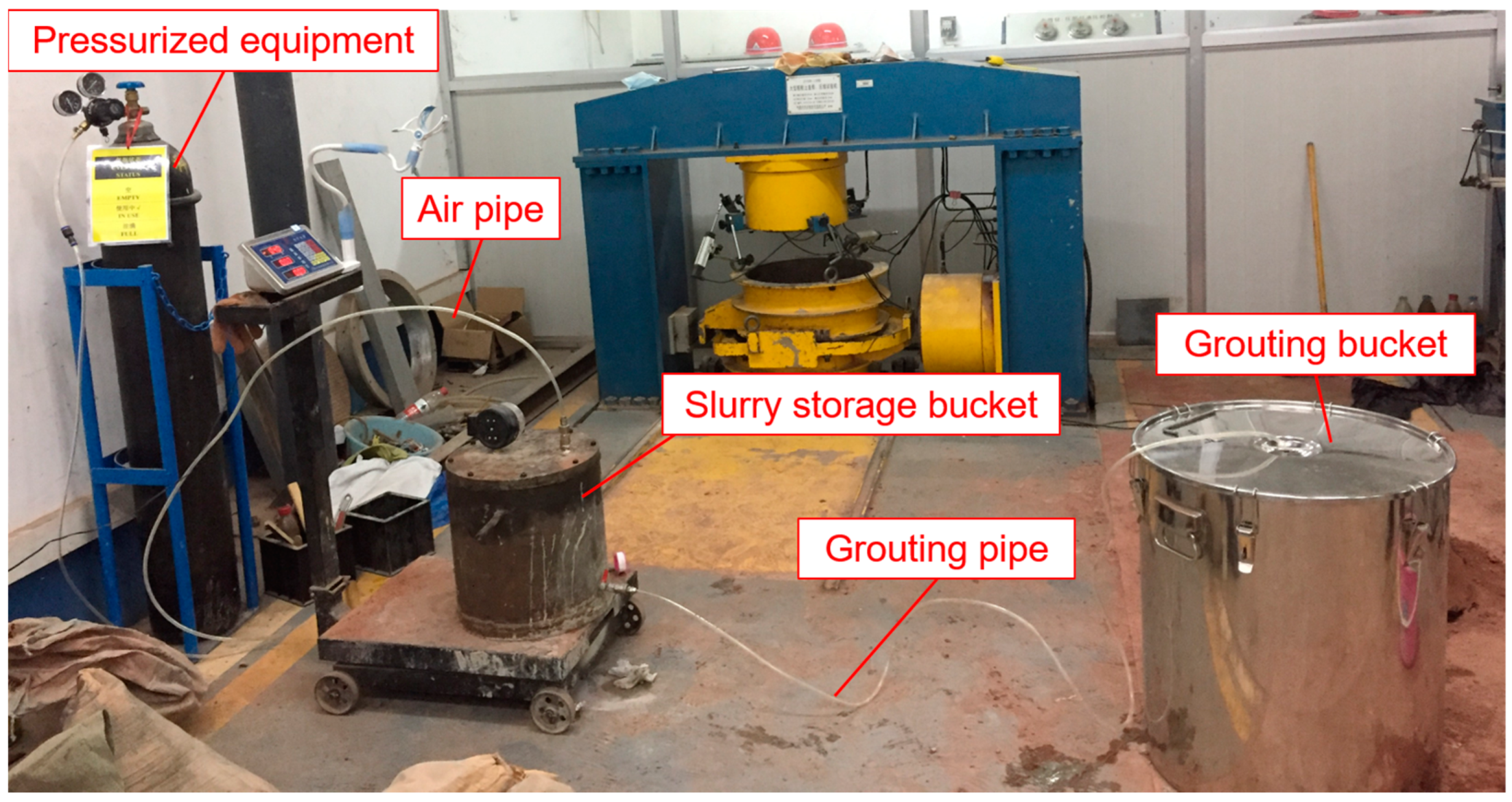
The core device of the grouting test is a self-designed grouting system, which can satisfactorily meet the test requirements of adjustable and monitorable grouting pressure, monitorable grouting volume, determinable grouting time, and removable grouted stone body. The grouting system includes four parts: pressurized equipment, slurry storage bucket, grouting bucket, and connecting device (air pipe and grouting pipe), as shown in Figure 3. The grouting bucket is a stainless steel bucket with a diameter of 55 cm, height of 63 cm, and thickness of 2.8 mm. The test cement materials in this paper were 42.5R ordinary silicate cement (a hydraulic cementitious material made of silicate cement clinker, 5–20% of mixed materials, and appropriate amount of gypsum finely ground) produced by Chongqing Xiaonanhai Cement Plant. The grouting slurry in this paper was pure cement slurry, which is a mixture of cement and water and does not contain gravel. The composition of the soil–rock mixture was clay and sandstone.
(2)
Test process
The indoor test process is as follows:
(a)
Control particle grading: soil–rock mixture sampling was carried out from the construction site to determine the particle gradation (shown in Figure 4), and the soil–rock mixture samples were configured in the room.
(b)
Control water content: The dried soil–rock mixture sample was mixed evenly one day in advance and laid flat in the aluminum box, sprinkled evenly with water, and mixed thoroughly to ensure that the water content was equal to the natural water content of the original soil–rock mixture, covered with plastic film for 24 h, and then taken, as shown in Figure 5.
(c)
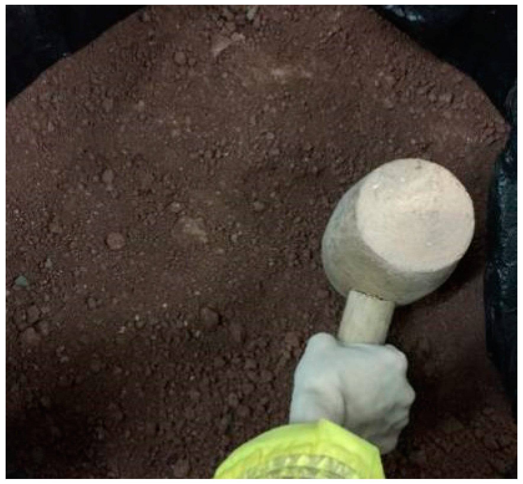
Soil–rock mixture specimen: In the grouting bucket against the wall set of plastic bags, the soil–rock mixture was added to the mold in 4 layers. Each layer was 150 mm thick, and the height was controlled in layers. The soil–rock mixture layer was compacted with a wooden compaction hammer according to the principle of light hammering and multi-striking to ensure that the dry density of the configured specimen was equal to the dry density of the original soil–stone mixture, as shown in Figure 6. To prevent the appearance of a preset weak surface between layers, surface chiseling treatment was carried out after each layer was compacted before adding soil samples.
(d)
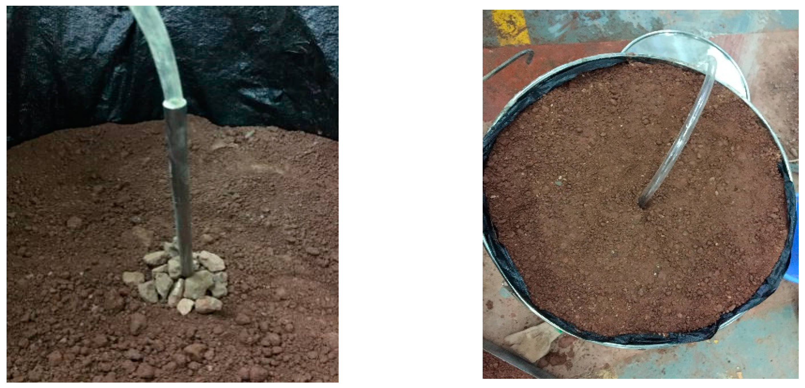
Buried pipe: After the soil–rock mixture sample was added to 3 layers, the grouting pipe was buried, and the position of the grouting pipe mouth was fixed. To prevent the soil–rock mixture in the mouth of the pipe from blocking the pipe, a layer of gravel was placed under the pipe mouth so that it was wrapped by gravel, and then the position of the grouting pipe was fixed, as shown in Figure 7. Then, the fourth layer of the soil–rock mixture was buried, compacted, and sealed with a cover.
(e)
Safety check: After connecting the device, we opened the inlet valve, closed the outlet valve, opened the main valve of the nitrogen tank, and adjusted the output pressure to 0.2 MPa. Then, we closed the main valve after the air pressure in the slurry storage barrel was stable. If the pressure value of the pressure gauge on the slurry storage barrel remained unchanged for 5 min, we considered the sealing gaskets, valves, and pipes as gas-tight at these critical connection locations and the device as safe.
(f)
Slurry making: First, we poured a specific mass of cement and water into the mixing barrel according to the water–cement ratio. Second, we used a handheld electric drill equipped with a cross-stirring bar to stir at a speed of (500 rpm) in the mixing barrel at a constant speed for 5 min, and finally, poured the cement slurry quickly through the funnel into the slurry storage barrel, installed a pressure gauge, and set the scale to zero (the slurry storage barrel was located on the scale).
(g)
Pressurized grouting: We set the grouting pressure to the test pressure, opened the slurry outlet valve, and started grouting.
(h)
End of grouting: The end of grouting was marked by no change in the amount of grouting for 5 min. We closed the valve, stopped timing, pulled out the grouting pipe, inserted it into the waste bucket, opened the valve, and waited until all the slurry flowed out and all the gas was discharged.

3.1.3. Basic Physical and Mechanical Parameters of the Soil

Groups #1 to #9 were indoor grouting test groups at different stone contents, with three levels of stone contents, void ratios, grouting pressures, and water–cement ratios, and group #10 was a pure soil test group. The parameters of the injected soil media in each group are shown in Table 2 for groups #1–10.

3.2. Field Grouting Tests

3.2.1. Test Conditions

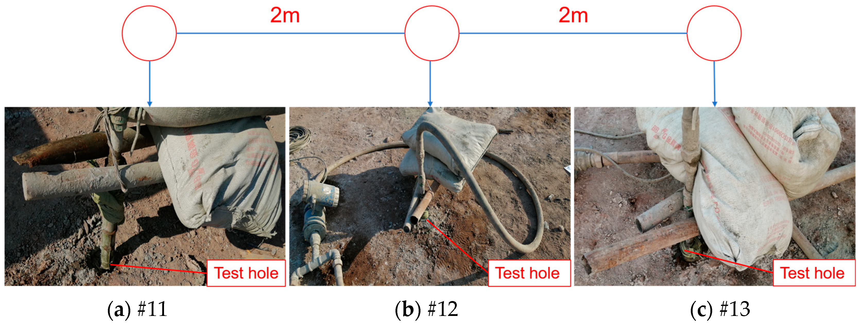
A field grouting test was carried out to verify the applicability of the calculation theory of the diffusion radius of fracture grouting. Based on the tunnel project between Wangjiacheng Station and Shengjibao Station of Chongqing Rail Transit Line 4, the grouting test was carried out on the ground surface at the beginning of TBM on the right line of YK47 + 780.110~YK48 + 011.110. A total of 3 point positions were arranged in this test in a single line with an interval of 2 m to prevent cross-grouting during the test. The test hole depth was set at 3 m, convenient for grouting effect verification through excavation. The grouting of the test hole was a single grouting under the same depth (3 m). The layout of the grouting test holes is shown in Figure 8.
The grouting test was conducted under a grouting pressure of 0.5 Mpa and a void ratio of 0.35. Slurry: ordinary Portland cement slurry; water–cement ratio: 0.6:1, 0.8:1, and 1:1. The stone content of the soil–rock mixtures measured on site was approximately 30%. The conditions of each grouting test hole are shown in Table 3.

3.2.2. Test Device

The configured slurry with different water–cement ratios entered the grouting pump via the suction pipe and was pumped through the discharge pipe to the grouting hole with a slurry flow meter connected in the middle. The grouting pump and the grouting line were selected to create the grouting system, as shown in Figure 9.

3.2.3. Basic Physical and Mechanical Parameters of the Soil

Groups #11–13 are the field grouting experimental groups under different water–cement ratios. The parameters of the injected soil medium in each group are shown in Table 2.

4. Results and Discussion

4.1. Mechanism of Slurry Diffusion of Indoor Grouting Tests

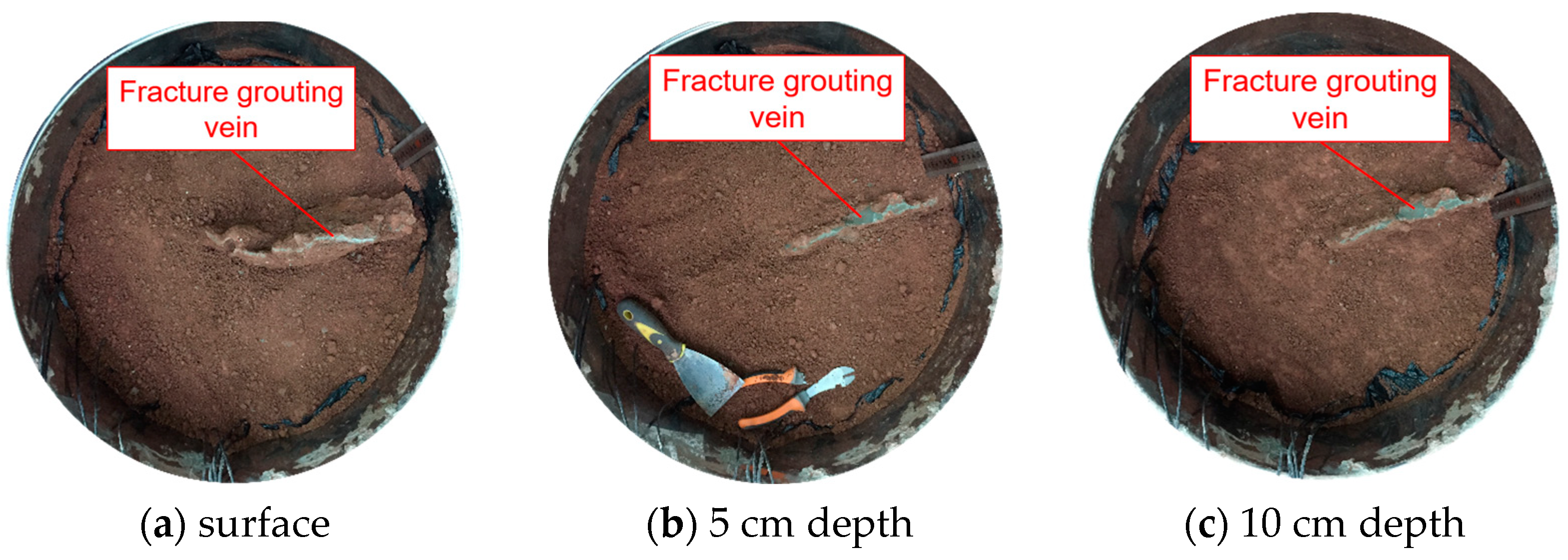
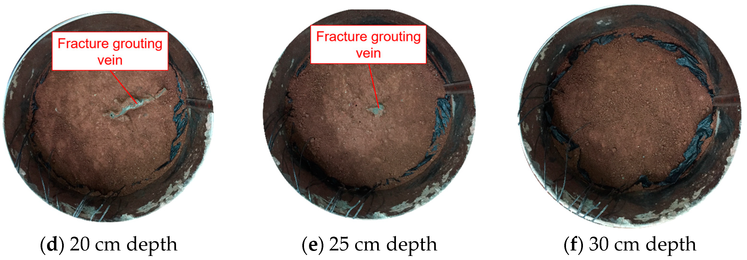
The #10 group of test concretions had irregularly oblate slice shapes and could not be obtained by toppling them as a whole to prevent them from breaking up during the toppling process, so they were measured using the “stratification method,” and a diffusion radius value of 21 cm was obtained. Images of each stratum were taken, as shown in Figure 10.
The layer-by-layer dissection of the concretion revealed that the concretion in the pure soil was oblate slice shape, and the diffusion path of the slurry in the pure soil was in one direction in the radial direction, thus forming an oblate slice shape concretion. A closer look at the cementation relationship between the slurry and the soil reveals that the slurry and the soil grains were not embedded in each other but had a demarcation line, as shown in Figure 11.
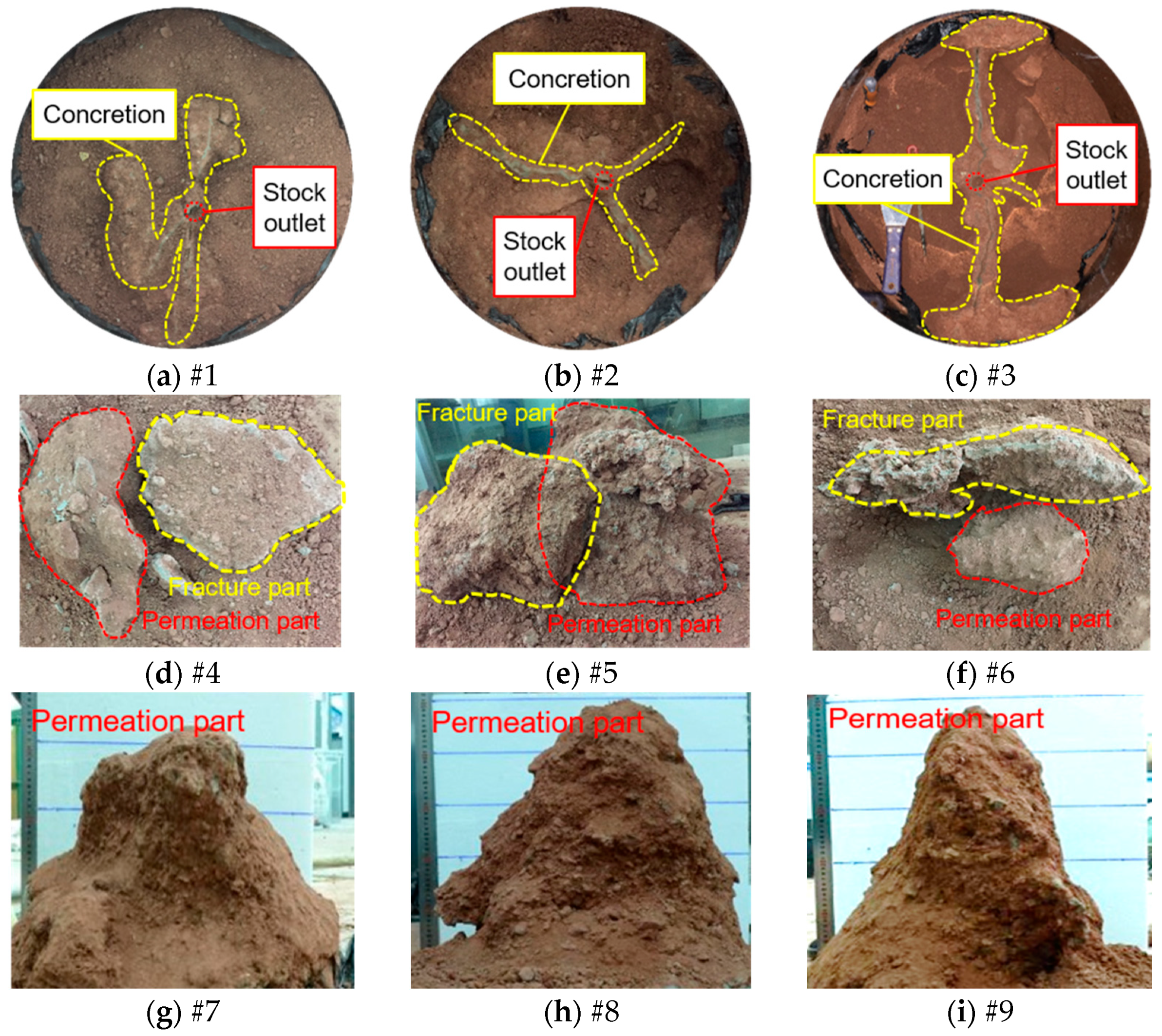
This means that the diffusion path of the slurry was not the soil pores, the slurry fractured the soil under pressure to create a new fracture, and the slurry diffused into the fracture. Therefore, the form of slurry diffusion in pure soil is fracture diffusion. The stratified measurement method measured the shape parameters of the test concretions in groups #1–3. The dumping method removed the test concretions in groups #4–9, and the shape parameters were measured by the “multiangle measurement method”. The concretions in groups #7–9 were taken out entirely, and their morphology was well preserved, as shown in Figure 12g–i. Among them, the concretions of groups #4–6 were not completely removed, and the concretions were damaged in the removal process. Only representative parts were preserved, and other broken parts were small in size and difficult to recover, as shown in Figure 12d–f. Groups #1–3 were measured by the stratified measurement method through active destruction, so the concretions were not retained, but the photos of each section were retained, among which the profile of the slurry outlet is shown in Figure 12a–c.
According to the diffusion form of the slurry in the indoor test of groups #1–9, analyzed by the morphology of the concretions, the morphology of the concretions in groups #1–3 was branching and scattering, and there were clear fracture paths in the images. The slurry and soil boundaries were clearly defined, showing the typical characteristics of fracture grouting. However, during the process of chiseling the concretions for filming, it was found that there were areas in the concretions where the slurry and soil were embedded and uniformly mixed, as shown in Figure 13. In Figure 13, from left to right, there are some blocks of concretions in groups #1, #2, and #3. The light-colored strip in the middle of the block shows the fracture surface of the slurry, and on both sides of the fracture surface are stone bodies mixed with soil, stone, and slurry, indicating that in groups #1–3 tests, permeation grouting was accompanied by fracture grouting, and the slurry took fracture cracks as the main circulation channel for fracture grouting. At the same time, the slurry penetrated the two walls of the crack under the action of grouting pressure. According to the average permeation depth of the samples, the relationship between the size of the permeation grouting radius of the three groups of tests can be determined as #3 > #2 > #1.
In addition, permeation diffusion processes also exist around the grouting pipe, as shown in Figure 14, which shows the enlarged profile of the concretion at the grouting outlet of group #3. There was a small scope of permeable grouting concretion near the outlet of the grouting pipe, and the permeation area surrounded the grouting outlet, which was close to a pair of concentric circles.
In group #1–3 tests, the slurry diffusion form was mainly in the form of fracture, and the diffusion radius of fracture grouting was between 20 and 40 cm. Although there was a small range of permeation grouting, the permeation grouting mainly occurred on both sides of the fracture surface, and the permeation grouting was attached to the fracture grouting with a permeation width of approximately 3–6 cm, which had little influence on the overall diffusion radius. Therefore, we considered the form of slurry diffusion in groups #1–3 as fracture diffusion.
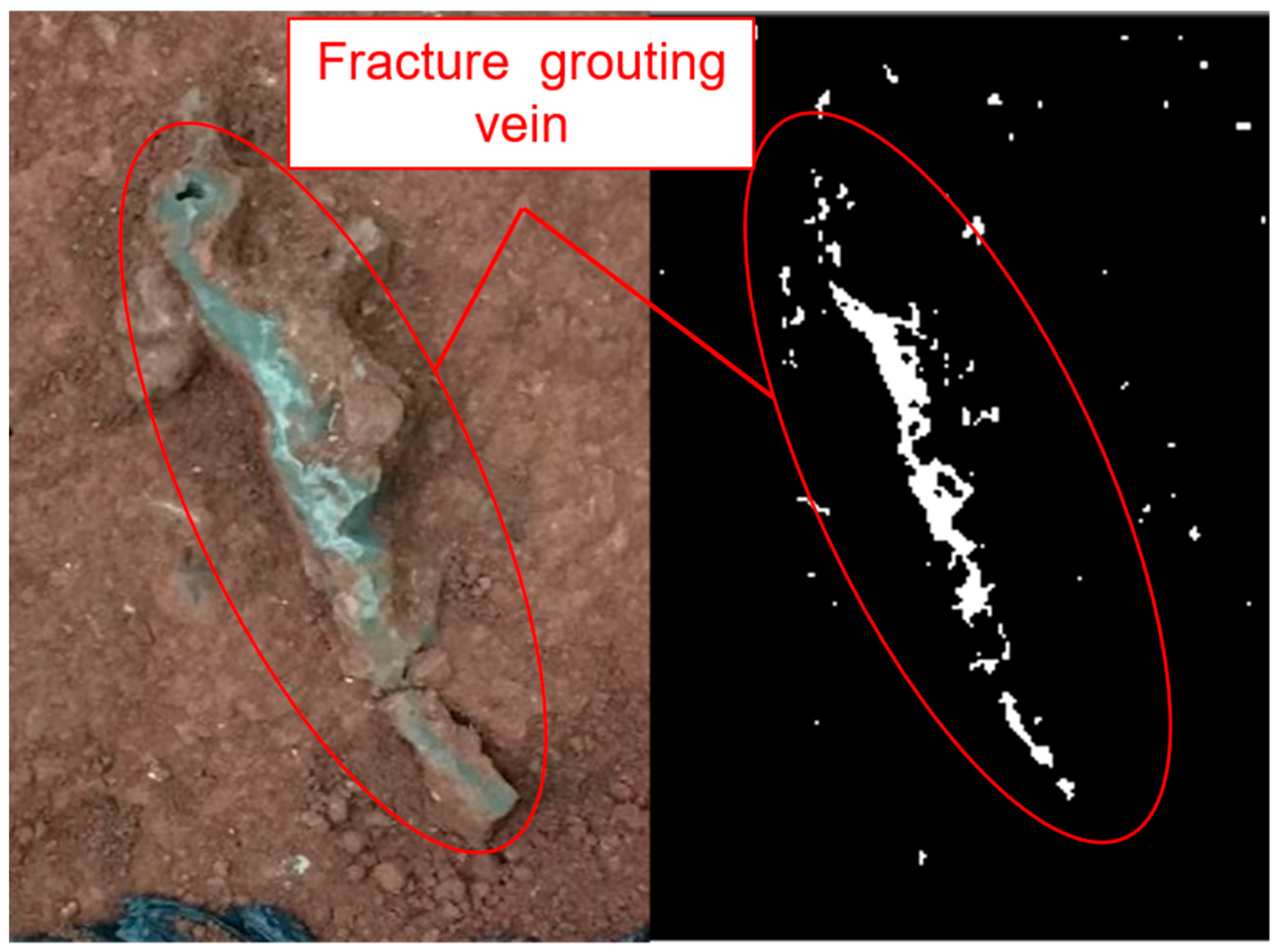
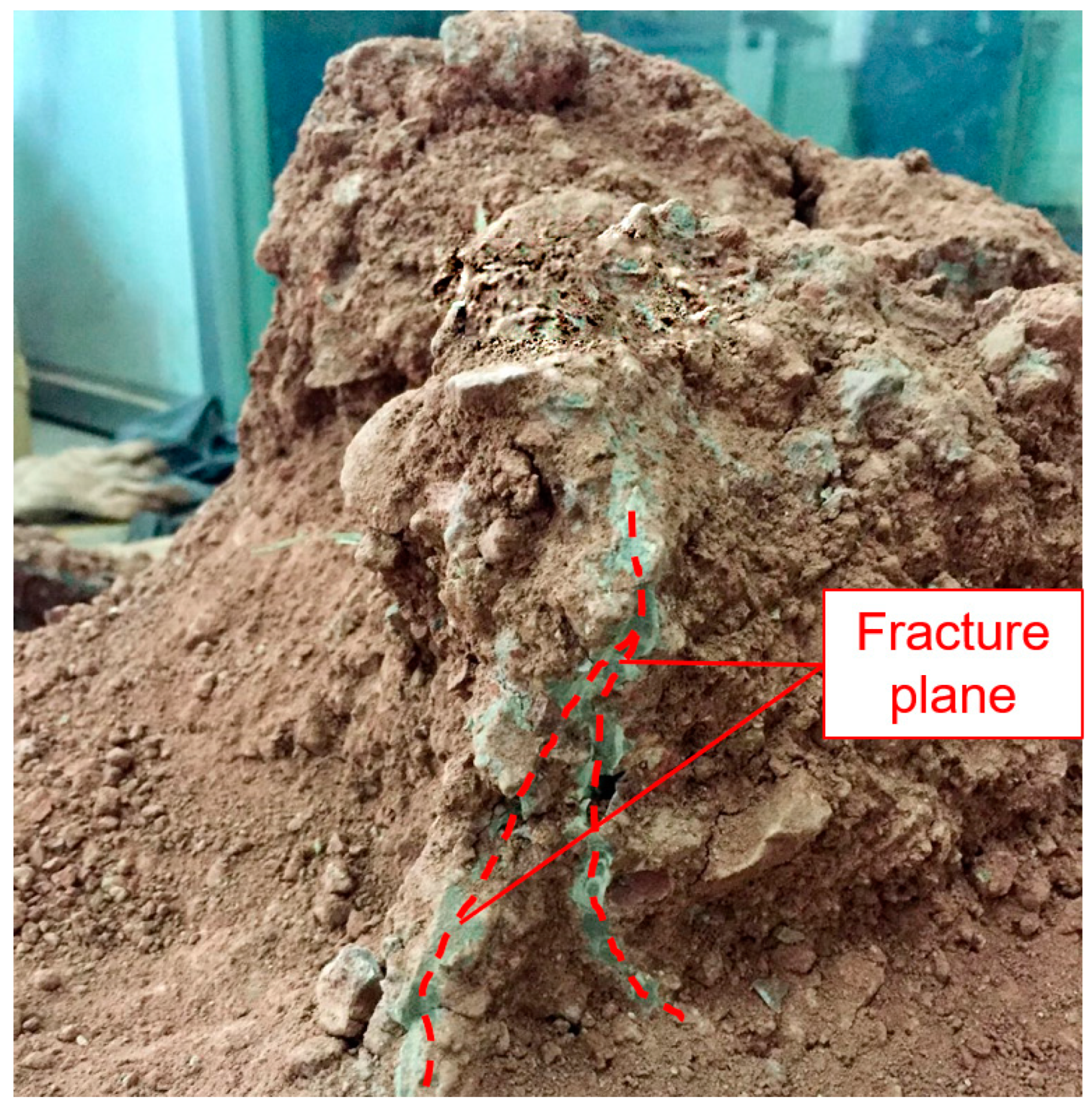
The test concretions in groups #7–9 were irregularly spheroidal, as shown in Figure 12g–i, where the slurry was evenly distributed with the soil and stones and glued to each other to form a whole, showing prominent permeation grouting characteristics, and their permeation grouting radius was between 25 and 40 cm. However, through careful observation, there were still features of fracture grouting on the concretions, as shown in Figure 15, which shows a partial view of the surface of the concretion of group #7. There were fracture grouting veins raised on the surface of the concretion, with clear lines, and there was no soil and stone inside, which is caused by fracture grouting.
The fracture plane was formed by the extension of the surface of the concretion formed by permeation diffusion. As a rule, when the permeability coefficient of the soil body is large, and the slurry has good groutability, it is not easy to produce fracture. This shows that when the radius of permeation grouting diffusion is large enough, the slurry fills the pores of the soil–rock mixtures, which makes the groutability poor, and the slurry will compress the soil body deformation under the action of grouting pressure and even make the soil body yield to crack. Then, the slurry is pressed into the cracks to cause fracture grouting.
According to the morphology of the concretions, groups #4–6 had a permeation grouting concretion centered on the grouting pipe opening, which was irregular and spherical in shape, with a radius of 10–25 cm. Additionally, there were several fracture faces in the concretions, and the permeation grouting concretions were weakly connected to the extended fracture faces, which were broken by the concentrated stress during dumping. The smaller fracture face fragments were challenging to recover, so the largest fracture face was taken as a representative, and its fracture grouting radius was measured, with a value of 10–20 cm. The difference between the radius of permeation grouting and the radius of fracture grouting was insignificant, so for groups #4–6, the slurry diffusion was in the form of both permeation and fracture diffusion. Therefore, the concretion consisted of two parts: one is the permeation grouting concretion centered at the mouth of the grouting pipe, and the other is a maximum fracture plane, as shown in Figure 12d–f.
For soil–rock mixtures with 50% stone content, permeation grouting, fracture grouting, or even both may occur under uniform soil–rock mixtures. This situation shows that the slurry is generally groutable for soil and rock mixtures with 50% stone content, and the slurry’s permeability depends on the slurry’s viscosity, the void ratio of the soil–rock mixtures, and the grouting pressure value. At the same time, the fracture pressure of the soil was less than the minimum grouting pressure in the test, which was 0.4 Mpa. Therefore, for soil–rock mixtures with stone contents near 50%, the design of grouting technical parameters should be carried out more strictly to ensure that the grouting effect is within the expected range.

4.2. Mechanism of Slurry Diffusion of Field Grouting Tests

Figure 16 shows the morphological image of the test concretion of groups #11–13. Figure 16 shows clear fracture paths in the morphological image of the concretion of groups #11–13, and the slurry veins are clearly visible, showing the typical characteristics of fracture grouting. However, during the process of removing the concretion, it was found that there was a small amount of grout and soil, and stone was interbedded and mixed evenly on the surface of the concretion.
Figure 17 shows the concretion fragment of groups #11–13, as shown in Figure 17. The concretions taken out only contain the cementation body composed of slurry and rock, without soil. This is because the slurry filled the void between the rock and wrapped the rock. The loose soil in the void and the soil in contact with the rock were squeezed out by the slurry, and the slurry in contact with the rock formed strong cementation of the slurry–rock cementation interface. According to measurement, the diffusion radius of the fracture grouting of the concretions in groups #11–13 was 30–40 cm. Although there was a small range of permeation grouting, permeation grouting mainly occurred on both sides of the fracture surface. The permeation grouting was attached to the fracture grouting, and the permeation width was approximately 4–6 cm, which had little influence on the overall diffusion radius. Therefore, the slurry diffusion form of groups #11–13 was fracture diffusion.

4.3. Diffusion Radius Results

According to the shape of the concretion, it can be judged that the grouting diffusion forms of the soil–rock mixtures include both permeation diffusion and fracture diffusion. The test results are shown in Table 4.

4.4. The Fracture Diffusion Formula of Bingham Fluid in Clay

Due to the thick slurry, low grouting pressure, and small particle size of the soil, its pores were relatively smaller, and the slurry had less groutability. The grouting process proceeded more slowly, and the grouting time was up to 12 min. The slurry flow rate was low, and the final grouting volume was 1.8 L.
The slurry was a Bingham fluid, and the Group #10 grouting test conformed to the Bingham fluid fracture grouting model, so its grouting pressure, diffusion radius, and grouting time relationship should conform to Equation (14).
Therefore, the theoretical diffusion radius R can be deduced from the parameter values and the relationship equation and compared with the slurry diffusion radius measured in the test to verify the correctness and applicability of the diffusion equation. After the measurement and calculation of the shear test, the calculation parameters of the #10 group of test soils are given, as shown in Table 5.
The calculated parameters in Table 5 were obtained from the experimental mechanical properties of the soil–rock mixture in the state of natural water content (10%), and the natural water content data were obtained from the survey report of the relying project (Wangjiacheng Station to Shengjiabao Station of Chongqing Railway Line 4 Phase II Project).
When the initial water content of the soil changes, the corresponding calculated parameter values (peak strength [39,40], elastic modulus [41], Poisson’s ratio, etc.) will change, and the corresponding calculated parameter values can be obtained from the mechanical property tests of soil–rock mixture at different water contents. They can be calculated by substituting into Equations (14) and (15).
The initiation fracture pressure was calculated and brought into the Bingham fluid fracture grouting diffusion formula (Equation (14)). The Squeeze Theorem was used to approach the unique real value, and the calculated result of the diffusion radius was 22.744 cm, while the test result of the grouting test concretion was 23.05 cm, with an error of 1.33%. The calculation result of the Bingham fluid fracture grouting diffusion formula was considered accurate. It is suitable for analyzing Bingham fluid fracture grouting in clay.

4.5. The Fracture Diffusion Formula of Bingham Fluid in the Soil–Rock Mixtures

It is generally accepted that the slurry flow pattern transforms with the change in the water–cement ratio. When the water–cement ratio is relatively large, the viscosity is small, and the slurry fluidity is strong. At this time, the slurry is a Newtonian fluid. With the decrease in the water–cement ratio, the slurry viscosity increases and is gradually transformed into a Bingham fluid. When the water–cement ratio of the slurry continues to decrease, and the viscosity increases to a certain extent, the slurry transforms into a power-law fluid. That is, when the water–cement ratio of the slurry is less than 0.6, it belongs to a power-law fluid; when the water–cement ratio is greater than 1.0, the slurry is transformed into a Newtonian fluid, and the Bingham fluid is between them.
The grouting diffusion models for each group of tests were classified, and the results are shown in Table 6.
Groups #6 and #7 belong to the Newtonian body permeation grouting case; #3, #6, and #13 belong to the Newtonian body fracture grouting case; #4, #5, #8, and #9 belong to the Bingham fluid permeation grouting case; and #1, #2, #4, #5, #11, and #12 belong to the Bingham fluid fracture grouting case. Since groups #7, #8, and #9 are mainly permeation diffusion, the fracture diffusion depth is small; #3, #6, and #13 belong to the Newtonian body fracture grouting case, so they are not discussed.
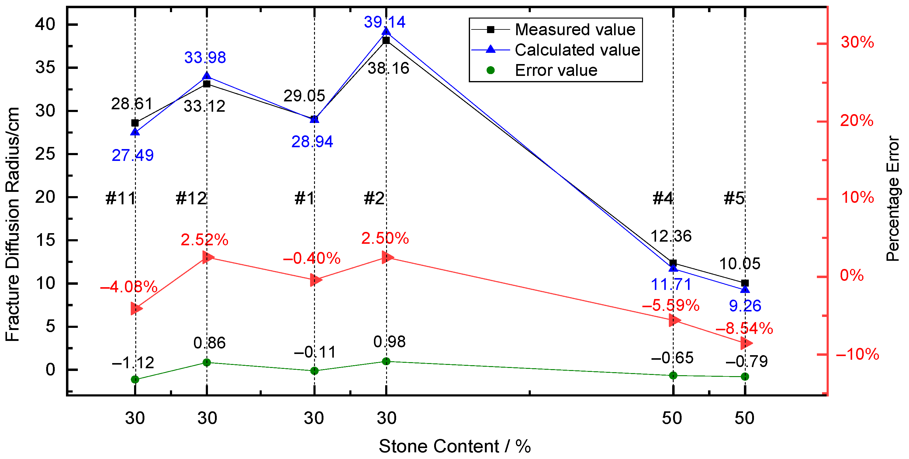
Therefore, the theoretical diffusion radius of each experimental group can be deduced according to the parameter values and the Bingham fluid fracture grouting diffusion formula (Equation (14)). For those that cannot be solved directly, the squeeze theorem is used to approximate the unique real numerical solution continuously. The calculated value is compared with the measured value, and the comparison results are shown in Figure 18.
As the test effects of groups #1, #2, #11, and #12 are dominated by fracture diffusion, permeation diffusion has less influence on their diffusion processes, so their permeation diffusion is not considered in the calculated values. The tests of groups #4 and #5 carry out both permeation diffusion and fracture diffusion processes, and both affect the diffusion effect of the slurry together, so both should be considered. Groups #1 and #2 were carried out in a single fracture grouting process, and the calculated results were very close to the measured values, with an error range of 3%. Although groups #11 and #12 were also carried out in a single fracture grouting process, the field test was easily disturbed by external conditions, so the error between the calculated results and the measured values was larger than that of groups #1 and #2 (the error value increased by approximately 2%), and the error range of groups #11 and #12 were within 5%. Compared with groups #1 and #2, the error values of the diffusion radius of groups #4 and #5 were also larger due to both permeation grouting and fracture grouting.
The above results also show that when a single fracture grouting is carried out in a grouting test, the results calculated by the diffusion radius formula are more accurate, while when permeation grouting and fracture grouting are carried out simultaneously in soil–rock mixtures, the results will be more inaccurate. This is because when permeation grouting and fracture grouting are carried out simultaneously, the two processes share grouting pressure, grouting time, and grouting volume, and it is not easy to segment the two processes quantitatively.
Despite individual cases of large errors, the test values for each group are still relatively close to the calculated values, indicating that the solution formula for the fracture diffusion radius of the Bingham fluid is applied to the fracture grouting diffusion of the soil–rock mixtures in general.
Since the object of the theoretical derivation and test in this paper is the soil–rock mixture in the low water level area, the influence of groundwater is not considered, and the calculation of grouting diffusion radius for the soil–rock mixture in the saturated state is not applicable.

5. Conclusions

The following conclusions can be drawn from the present study:
(1)
Based on the rheological characteristics of Bingham fluid and the assumption of a spherical diffusion model of grouting, the flow equation of the Bingham fluid was obtained, and the formula for calculating the fracture diffusion radius of Bingham fluid was derived. The formula considers the influence of the main parameters, such as stone content, void ratio, water–cement ratio, and grouting pressure.
(2)
The slurry’s diffusion mode in the soil–rock mixtures (stone content 30%) can be summarized as the main-fracture-sub-permeation mode. In the middle period before diffusion, the structure of the backfill of the soil–stone mixtures is loose before reinforcement, the initial kinetic energy of slurry diffusion is the largest, and the resistance to overcome is small. At this time, the midpoint of the slurry outlet of the cuff pipe is the midpoint, the main slurry veins and secondary slurry veins are formed rapidly along the soft surface, and fracture diffusion is dominant at this stage. At the later stage of diffusion, the void ratio in the reinforced area decreases, and the resistance of the slurry to continue expanding along the main slurry vein or secondary slurry vein channels increases so that the pores can only be filled along the vicinity of the main slurry vein or the boundary area, mainly by permeation diffusion. Finally, the slurry–rock cement skeleton is formed, and the skeleton is wrapped and packed with the soil in the grouting to strengthen the concretion.
(3)
The formula for fracture diffusion of a Bingham fluid is derived. The formula is brought into the test conditions under the corresponding working conditions for calculation. After comparing the calculated values with the test values for verification (the error of indoor model test results is less than 3%, and the error of field test results is less than 5%), it is confirmed that the formula applies to various working conditions of fracture grouting of the soil–rock mixtures and has a good prediction effect on the value of the fracture diffusion radius.

Author Contributions

Z.Z. designed the experiment. J.L. and C.B. carried out theoretical derivation and experimental analysis. All authors have read and agreed to the published version of the manuscript.

Funding

This work is supported by The Natural Science Foundation of Chongqing (CSTB2022NSCQ-MSX0887): Research on the construction technology of long and deep soil-rock mixed backfill tunnel composite shield.

Institutional Review Board Statement

Not applicable.

Informed Consent Statement

Not applicable.

Data Availability Statement

The data used to support the findings of this study are available from the corresponding authors upon request.

Conflicts of Interest

The authors declare no conflict of interest.

References

  1. Xu, W.J.; Hu, R.L. Conception, classification and significations of Soil-rock mixture. Hydrogeol. Eng. Geol. 2009, 36, 50–56, 70. (In Chinese) [Google Scholar]
  2. The Research Group of the Grouting Theories and Case Histories. The Grouting Theories and Case Histories; Science Press: Beijing, China, 2001; pp. 115–118. (In Chinese) [Google Scholar]
  3. Sun, F.; Chen, T.L.; Zhang, D.L.; Zhang, Z.J.; Li, P.F. Study on Fracture Grouting Mechanism in Subsea Tunnel Based on Bingham Fluids. J. Beijing Jiaotong Univ. 2009, 33, 1–6. (In Chinese) [Google Scholar]
  4. Zhong, Z.L.; Tu, Y.L.; He, X.Y.; Feng, J.H.; Wang, Z.L. Research Progress on Physical Index and Strength Characteristics of Bimsoils. Chin. J. Undergr. Space Eng. 2016, 12, 1135–1144. (In Chinese) [Google Scholar]
  5. Zhang, J.X. Mechanism of Fracture Grouting of Power-law Fluid. J. Yangtze River. Sci. Res. Inst. 2016, 33, 113–118. (In Chinese) [Google Scholar]
  6. Zhang, Z.L.; Shao, Z.S.; Fang, X.B.; Lian, X.J. Research on the Fracture Grouting Mechanism and PFC Numerical Simulation in Loess. Adv. Mater Sci. Eng. 2018, 2018, 4784762. [Google Scholar] [CrossRef] [Green Version]
  7. Chen, T.L.; Zhang, L.Y.; Zhang, D.L. An FEM/VOF hybrid formulation for fracture grouting modeling. Comput. Geotech. 2014, 2014, 14–27. [Google Scholar] [CrossRef]
  8. Park, D.; Oh, J. Permeation grouting for remediation of dam cores. Eng. Geol. 2018, 233, 63–75. [Google Scholar] [CrossRef]
  9. Funehag, J.; Fransson, A. Sealing narrow fractures with a Newtonian fluid: Model prediction for grouting verified by field study. Tunn. Undergr. Space Technol. 2006, 21, 492–498. [Google Scholar] [CrossRef]
  10. Sarris, E.; Papanastasiou, P. Numerical modeling of fluid-driven fractures in cohesive poroelastoplastic continuum. Int. J. Numer. Anal. Methods Geomech. 2013, 37, 1822–1846. [Google Scholar] [CrossRef]
  11. Bezuijen, A.; te Grotenhuis, R.; van Tol, A.F.; Bosch, J.W.; Haasnoot, J.K. Analytical Model for Fracture Grouting in Sand. J. Geotech. Geoenviron. 2011, 137, 611–620. [Google Scholar] [CrossRef]
  12. Yun, J.W.; Park, J.J.; Kwon, Y.S.; Kim, B.K.; Lee, I.M. Cement-based fracture grouting phenomenon of weathered granite soil. KSCE J. Civ. Eng. 2017, 21, 232–242. [Google Scholar] [CrossRef]
  13. Fattah, M.Y.; Al-Saidi, A.A.; Jaber, M.M. Improvement of bearing capacity of footing on soft clay grouted with lime-silica fume mix. Geomech. Eng. 2015, 8, 113–132. [Google Scholar] [CrossRef]
  14. Kim, D.; Park, K. Evaluation of the grouting in the sandy ground using bio injection material. Geomech. Eng. 2017, 12, 739–752. [Google Scholar] [CrossRef]
  15. Neupane, D.; Yasuhara, H.; Kinoshita, N.; Putra, H. Distribution of grout material within 1-m sand column in insitu calcite precipitation technique. Soils Found. 2015, 55, 1512–1518. [Google Scholar] [CrossRef] [Green Version]
  16. Saiyouri, N.; Jason, L.; Chupin, O.; Hicher, P.Y. Modeling and acoustic monitoring of grout propagation in sands. Ground. Improv. 2008, 161, 143–152. [Google Scholar] [CrossRef] [Green Version]
  17. Cheng, P.D.; Li, L.; Tang, J.; Wang, D.Z. Application of Time-Varying Viscous Grout in Gravel foundation Anti-Seepage Treatment. J. Hydrodyn. 2011, 23, 391–397. [Google Scholar] [CrossRef]
  18. Jiang, N.; Zhao, J.H.; Sun, X.Z.; Bai, L.Y.; Wang, C.X. Use of fly ash slurry in backfill grouting in coal mines. Heliyon 2017, 3, e00470. [Google Scholar] [CrossRef]
  19. Funehag, J.; Thörn, J. Radial permeation of cementitious grout-Laboratory verification of grout spread in a fracture model. Tunn. Undergr. Space Technol. 2018, 72, 228–232. [Google Scholar] [CrossRef]
  20. Mohajerani, S.; Baghbanan, A.; Bagherpour, R.; Hashemolhosseini, H. Grout permeation in fractured rock mass using a new developed explicit algorithm. Int. J. Rock Mech. Min. 2015, 80, 412–417. [Google Scholar] [CrossRef]
  21. Mohajerani, S.; Baghbanan, A.; Wang, G.; Forouhandeh, S.F. An efficient algorithm for simulating grout propagation in 2D discrete fracture networks. Int. J. Rock Mech. Min. 2017, 98, 67–77. [Google Scholar] [CrossRef]
  22. Zou, L.C.; Håkansson, U.; Cvetkovic, V. Two-phase cement grout propagation in homogeneous water-saturated rock fractures. Int. J. Rock Mech. Min. 2018, 106, 243–249. [Google Scholar] [CrossRef]
  23. Yang, Z.Q.; Hou, K.P.; Guo, T.T. Research on Time-Varying Behavior of Cement Grouts of Different Water-Cement Ratios. Appl. Mech. Mater. 2011, 71–78, 4398–4401. [Google Scholar] [CrossRef]
  24. Zheng, G.; Zhang, X.S.; Diao, Y.; Lei, H.Y. Experimental study on the performance of compensation grouting in structured soil. Geomech. Eng. 2016, 10, 335–355. [Google Scholar] [CrossRef]
  25. Zhou, Z.; Cai, X.; Du, X.M.; Wang, S.Y.; Ma, D.; Zang, H.Z. Strength and filtration stability of cement grouts in porous media. Tunn. Undergr. Space Technol. 2019, 89, 1–9. [Google Scholar] [CrossRef]
  26. Azadi, M.R.; Taghichian, A.; Taheri, A. Optimization of cement-based grouts using chemical additives. J. Rock Mech. Geotech. Eng. 2017, 9, 623–637. [Google Scholar] [CrossRef]
  27. Kongar-Syuryun, C.; Aleksakhin, A.; Khayrutdinov, A.; Tyulyaeva, Y. Research of rheological characteristics of the mixture as a way to create a new backfill material with specified characteristics. Mater. Today Proc. 2021, 38, 2052–2054. [Google Scholar] [CrossRef]
  28. Ermolovich, E.A.; Ivannikov, A.L.; Khayrutdinov, M.M.; Kongar-Syuryun, C.B.; Tyulyaeva, Y.S. Creation of a Nanomodified Backfill Based on the Waste from Enrichment of Water-Soluble Ores. Materials 2022, 15, 3689. [Google Scholar] [CrossRef]
  29. Adigamov, A.; Rybak, J.; Golovin, K.; Kopylov, A. Mechanization of stowing mix transportation, increasing its efficiency and quality of the created mass. Transp. Res. Procedia 2021, 57, 9–16. [Google Scholar] [CrossRef]
  30. Khayrutdinov, A.; Kongar-Syuryun, C.; Kowalik, T.; Faradzhov, V. Improvement of the backfilling characteristics by activation of halite enrichment waste for non-waste geotechnology. IOP Conf. Ser. Mater. Sci. Eng. 2020, 867, 012018. [Google Scholar] [CrossRef]
  31. Liao, Z.; Feng, T. Mechanism and Application of Layered Grouting Reinforcement for Fractured Coal and Rock Roadway. Appl. Sci. 2023, 13, 724. [Google Scholar] [CrossRef]
  32. Zhu, Y.; Wang, X.; Deng, S.; Chen, W.; Shi, Z.; Xue, L.; Lv, M. Grouting Process Simulation Based on 3D Fracture Network Considering Fluid-Structure Interaction. Appl. Sci. 2019, 9, 667. [Google Scholar] [CrossRef] [Green Version]
  33. Ding, W.; Duan, C.; Zhang, Q. Experimental and Numerical Study on a Grouting Diffusion Model of a Single Rough Fracture in Rock Mass. Appl. Sci. 2020, 10, 7041. [Google Scholar] [CrossRef]
  34. Sun, S.R.; Xu, P.L.; Wu, J.M.; Wei, J.H.; Fu, W.G.; Liu, J.; Kanungo, D.P. Strength parameter identification and application of soil-rock mixtures for steep-walled talus slopes in southwestern China. Bull. Eng. Geol. Environ. 2014, 73, 123–140. [Google Scholar] [CrossRef]
  35. Wang, Y.; Li, X. Experimental study on cracking damage characteristics of a soil and rock mixture by UPV testing. Bull. Eng. Geol. Environ. 2015, 74, 775–788. [Google Scholar] [CrossRef]
  36. Zhou, Z.; Yang, H.; Xing, K.; Gao, W.Y. Prediction models of the shear modulus of normal or frozen Soil-rock mixtures. Geomech. Eng. 2018, 15, 783–791. [Google Scholar] [CrossRef]
  37. Meng, Q.X.; Wang, H.L.; Xu, W.Y.; Cai, M. A numerical homogenization study of the elastic property of a soil-rock mixture using random mesostructure generation. Comput. Geotech. 2018, 98, 48–57. [Google Scholar] [CrossRef]
  38. Shan, P.F.; Lai, X.P. Mesoscopic structure PFC∼2D model of soil rock mixture based on digital image. J. Vis. Commun. Image Represent. 2019, 58, 407–415. [Google Scholar] [CrossRef]
  39. Zhang, L.L.; Fredlund, D.G.; Fredlund, M.D.; Wilson, G.W. Modeling the unsaturated soil zone in slope stability analysis. Can. Geotech. J. 2014, 51, 1384–1398. [Google Scholar] [CrossRef]
  40. Chen, L.X.; Ghorbani, J.; Zhang, C.S.; Dutta, T.T.; Kodikara, J. A novel unified model for volumetric hardening and water retention in unsaturated soils. Comput. Geotech. 2021, 140, 104446. [Google Scholar] [CrossRef]
  41. Lu, N.; Kaya, M. Power Law for Elastic Moduli of Unsaturated Soil. J. Geotech. Eng. 2014, 140, 46–56. [Google Scholar] [CrossRef]
  42. Ruan, W.J. Research on diffusion of grouting and basic properties grouts. Chin. J. Geotech. Eng. 2005, 69–73. (In Chinese) [Google Scholar]
  43. Zou, J.F.; Li, L.; Yang, X.L.; Hu, Z.N. Mechanism analysis of fracture grouting in soil. Rock Soil Mech. 2006, 27, 625–628, 642. (In Chinese) [Google Scholar]
  44. Wu, X.X. Building Foundation Engineering; South China University of Technology Press: Guangzhou, China, 2006; pp. 63–66. (In Chinese) [Google Scholar]
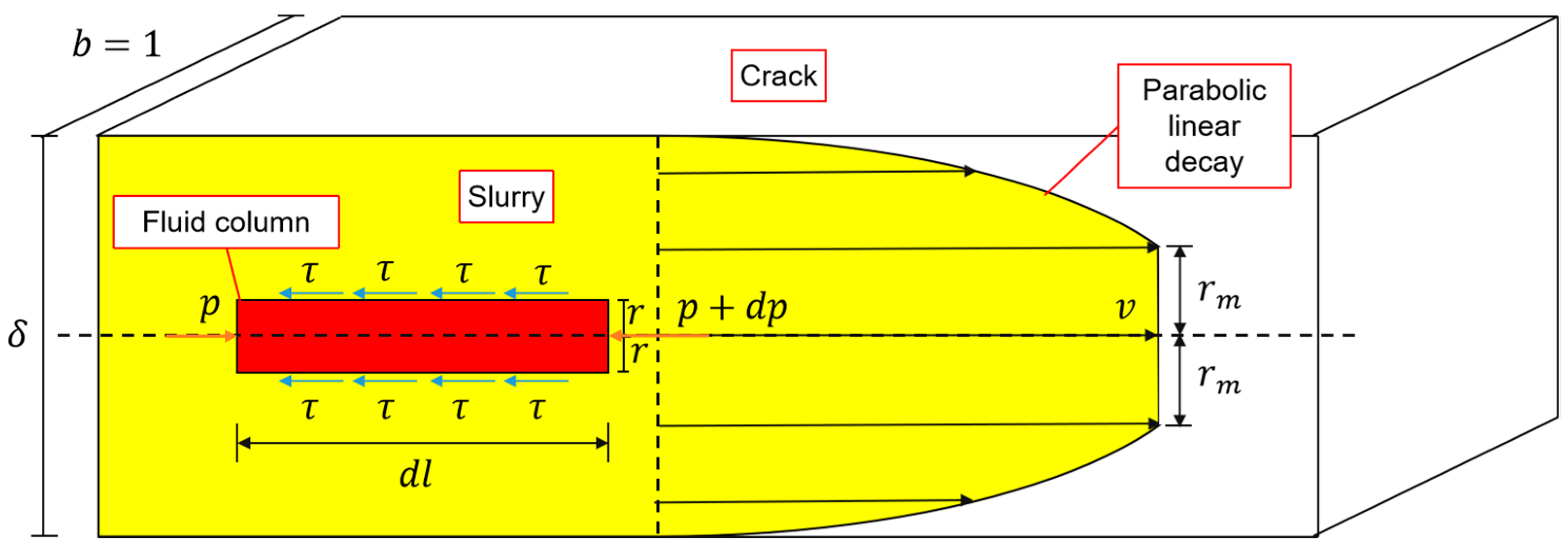
Figure 1. Bingham fluid flow in a crack.
Applsci 13 04730 g001
Figure 2. Slurry fracture diffusion model.
Applsci 13 04730 g002
Figure 3. Diagram of the test device.
Applsci 13 04730 g003
Figure 4. Particle grading test procedure. (a) Drying the samples; (b) hammering the fine-grained soil; (c) sieving the samples; (d) separating each particle size and weighing.
Applsci 13 04730 g004
Figure 5. Control water content.
Applsci 13 04730 g005
Figure 6. Tap and compact.
Applsci 13 04730 g006
Figure 7. Burying pipe.
Applsci 13 04730 g007
Figure 8. Grouting hole layout plan.
Applsci 13 04730 g008
Figure 9. Grouting system: (a) slurry agitator; (b) reserve pit; (c) grouting pump; (d) slurry flow meter.
Applsci 13 04730 g009
Figure 10. The concretion sections of Group #10.
Applsci 13 04730 g010aApplsci 13 04730 g010b
Figure 11. Part of the concretion of Group #10.
Applsci 13 04730 g011
Figure 12. Concretion shape of Groups #1–9.
Applsci 13 04730 g012
Figure 13. Concretion fragment of Groups #1–3.
Applsci 13 04730 g013
Figure 14. Concretion section of Group #3.
Applsci 13 04730 g014
Figure 15. Detailed drawing of the concretion of Group #7.
Applsci 13 04730 g015
Figure 16. Concretion shape of groups #11–13.
Applsci 13 04730 g016
Figure 17. Concretion fragment of Groups #11–13.
Applsci 13 04730 g017
Figure 18. Comparison of calculated values of diffusion radius and measured values.
Applsci 13 04730 g018
Table 1. Orthogonal test table of the grouting test.
GroupsStone Content (%)Void RatioWater-Cement RatioGrouting Pressure
(MPa)
1300.30.60.4
2300.350.80.7
3300.411
4500.30.61
5500.350.80.4
6500.410.7
7700.310.7
8700.350.61
9700.40.80.4
1000.30.60.4
Table 2. Injected media parameters.
GroupsVoid Ratio
e
Nonuniformity Coefficient
Cu
Coefficient of Curvature
Cc
d20 (mm) Internal   Friction   Angle   φ (°)Shearing Strength
σ c   ( kPa )
Cohesive Force c (kPa)Compression Modulus
E s   ( MPa )
10.337.001.320.2316.7110237.17
20.3537.001.320.2316.7110237.17
30.437.001.320.2316.7110237.17
40.356.432.930.612414815.37.35
50.3556.432.930.612414815.37.35
60.456.432.930.612414815.37.35
70.329.173.722.529.117512.18.3
80.3529.173.722.529.117512.18.3
90.429.173.722.529.117512.18.3
100.322.500.430.151310737.47.12
11–130.3556.093.79116.7110237.17
Table 3. Grouting test condition.
GroupsStone Content (%)Void RatioWater-Cement RatioGrouting Pressure
(Mpa)
11300.350.60.5
12300.350.80.5
13300.351.00.5
Table 4. Indoor grouting diffusion test results.
GroupsStone Content
(%)
Permeation Diffusion Radius (cm)Fracture Diffusion
Radius (cm)
1303.4229.05
2304.8538.16
3306.4237.09
45013.1512.36
55018.3610.05
65025.3610.25
77028.965.64
87028.644.42
97038.794.21
100023.05
11303.9228.61
12304.6033.12
13305.5339.87
Table 5. Soil parameters of Group #10.
μ η p   ( MPa · s ) β p t   ( kPa ) E s   ( MPa ) φ σ c   ( kPa ) Mm
0.35118116.82.4928.313°1071.582
Table 6. Classification of diffusion forms.
Slurry Flow PatternForms of DiffusionGroups
Newtonian fluidPermeation diffusion#6, 7
Newtonian fluidFracture diffusion#3, 6, 13
Bingham fluidPermeation diffusion#4, 5, 8, 9
Bingham fluidFracture diffusion#1, 2, 4, 5, 11, 12
Disclaimer/Publisher’s Note: The statements, opinions and data contained in all publications are solely those of the individual author(s) and contributor(s) and not of MDPI and/or the editor(s). MDPI and/or the editor(s) disclaim responsibility for any injury to people or property resulting from any ideas, methods, instructions or products referred to in the content.