Article

Multirobot Task Planning Method Based on the Energy Penalty Strategy

1
Industrial Innovation Technology Research Co., Ltd., Anhui Polytechnic University, Wuhu 241000, China
2
School of Mechanical & Automotive Engineering, Anhui Polytechnic University, Wuhu 241000, China
*
Author to whom correspondence should be addressed.
Appl. Sci. 2023, 13(8), 4887; https://doi.org/10.3390/app13084887
Submission received: 28 February 2023 / Revised: 11 April 2023 / Accepted: 11 April 2023 / Published: 13 April 2023

Abstract

:
In multirobot task planning, the goal is to meet the multi-objective requirements of the optimal and balanced energy consumption of robots. Thus, this paper introduces the energy penalty strategy into the GA (genetic algorithm) to achieve the optimization of the task planning of multiple robots in different operation scenarios. First, the algorithm model is established, after which the objective function is constructed by taking the energy excess of the relative average energy consumption of each robot as the penalty energy, along with the total energy consumption of multiple robots. In the genetic operation, two-segment chromosome coding is used to realize the iterative optimization of the number and task sequences of robots through diversified cross and mutation operators. Then, in the task scenario with obstacles, the A* (A-Star) algorithm and GA are used to plan the optimal obstacle avoidance path and to realize the secondary optimization of the robot task sequence without changing the number of tasks. During optimization, the energy penalty strategy imposes punishment on the objective function through the size of the penalty energy, enabling the robot energy consumption to reach an equilibrium state by maintaining the total energy consumption at the minimum. Finally, the MATLAB platform is used to conduct the simulation experiments to compare with basic genetic algorithms and penalty function algorithms, after which the optimal allocation scheme and energy consumption iteration of the algorithm are analyzed under different robot numbers, task numbers, and task scenarios, and the simulation results include robot task sequences, total energy consumption, average energy consumption, and standard deviation of energy consumption.

1. Introduction

With the continuous development of mobile robot technology, efficient cooperative control makes it possible for mobile robot clusters to complete complex tasks, thus providing an important tool or enabler for task planning [1,2]. Such technology has been widely used in the industries of factory automation [3], warehouse [4], medical treatment [5], fire rescue [6], and so on.
Multirobot task allocation (MRTA) decomposes a task into several subtasks under the constraint conditions of robot performance and load capacity, and coordinates the matching relationship between tasks and robots based on the principle of minimizing energy consumption and execution time. The goal is to obtain the optimal task allocation execution sequence and path for each robot to avoid task conflict, imbalance, and other problems and realize the reasonable allocation of resources. MRTA involves related technologies such as robot dynamic model [7], robot navigation [8] and environmental detection [9,10], graph search method [11], architecture for multirobot coordination [12], and so on. At present, scholars pay more attention to the research of algorithm models and implementation methods, usually using centralized and distributed task allocation models and algorithms to solve MRTA problems [13,14,15]. Distributed task allocation models mainly include game theory [16], auction algorithm [17], competitive coordination [18], the MTSP (Multiple Traveling Salesman Problem) model [19,20], and the VRP (Vehicle Routing Problem) model [21]. Many heuristic algorithms have been extensively applied in task sequence optimization and robot collaborative control, such as the neural network-based auction scheme [22], genetic algorithm for industrial plant inspection [13], and colony algorithm for agricultural machinery operation [23]. There are other methods that focus on obstacle avoidance path planning for robots to optimize task costs. Shuai et al. [24] proposed an optimal task decision method that indicates the optimal sequence and path for robots to complete certain tasks, thereby enabling warehouse robots to make optimal task decisions at minimum costs. An improved ant colony algorithm [25] coordinates the path of robots based on the priority of their residual power distribution. Because the APF (Artificial Potential Field) path planning algorithm can easily fall into the local minimum [26], Tuazon et al. [27] integrated fuzzy logic into the APF algorithm to identify and avoid local minima. The A* algorithm usually uses path length as an evaluation function and is widely used and effective in path planning [28,29,30].
Through the above analysis, the application of the genetic algorithm and A* algorithm in the MRTA has shown good results [31,32,33]. However, the performance of these algorithms largely depends on the quality of the heuristic algorithm of the fitness function. Therefore, an algorithm model construction of the energy penalty strategy for the optimal and balanced control of energy consumption in multirobot cooperative operations is proposed. The proposed model combines GA and A* algorithm to optimize the MRTA and task sequence in stages, and verifies the algorithm performance through multiple experiments. Compared to the algorithm [34], the total energy consumption is reduced by 0.3%, the standard deviation is reduced by 29.6%, and the optimization time reduced by about 2 s.
The paper is organized as follows. The next section provides the problem statement and algorithm description. The description of the algorithm model is addressed in Section 3, including the computing methods of constraint conditions, objective functions, robot energy consumption, and other related parameters. The algorithm implementation for solving the MRTA is presented in Section 4, including coding methods, genetic operations, and algorithm steps. In Section 5, experimental and simulation results are given. Finally, the conclusion of this paper is drawn in Section 6.

2. Problem and Algorithm Description

Multirobot task planning reasonably allocates multiple tasks to a multirobot system and defines the task sequence with the goal of achieving the minimum cost of all tasks, such as the shortest total path (or time) and the least total energy consumption, among others. This kind of task planning covers task allocation, task sequence planning, and path planning. Suppose the number of robots is n, the number of tasks is m, and m 2 n . It is required that each robot can only perform one task at the same time, and each task only needs one robot to complete it at one time. The cost of each robot completing its task is expressed as C o s t = C i | i = 1 , 2 , , n . The optimal task planning scheme minimizes the total cost and is expressed as S u m C o s t = i = 1 n C i .
This paper constructs an algorithm model based on the idea of energy penalty. The proposed model takes the robot energy consumption as the optimization goal and the robot and task attributes as constraints; it also uses GA to achieve the optimal task allocation and execution sequence optimization results. In path planning, the punishment mechanism is used again according to the obstacle avoidance requirements of the actual path, and the GA and A* methods are used to optimize the task sequence of the robot to achieve the balanced optimization of the energy consumption of multiple robots. The algorithm framework is shown in Figure 1.
When researching multirobot task assignments and path planning, an energy penalty strategy is proposed to solve the problem of energy consumption balance among multiple robots. Its main idea is to calculate and compare the total and average energy consumption of robots in task allocation and path planning to obtain the penalty energy for each robot to complete the task, after which it introduces the penalty energy into the optimization objective function. If the penalty energy value of a robot is larger, it means that the task of the robot is heavy, and the energy consumption of the system is unbalanced. As a penalty item in the algorithm, further optimization of robot task allocation can be achieved. The formal description of penalty energy P E i is shown in Equation (1):
P E i = E R i E X ¯ i f P i α 0   e l s e P i = E R i E X ¯ E X ¯ , i = 1 , 2 , 3 , , n
where E R i is the energy consumed by robot i, i = 1 n E R i is the total energy consumed by all robots, which is the sum of the energy consumed by all robots to complete their respective tasks, E X ¯ = ( i = 1 n E ( R i ) ) / n is the average energy consumption, which means the average of the total energy consumption of n robots, P i is the relative error of robot i energy consumption, and α is the energy consumption threshold. The energy consumption of robots is related to task parameters such as task path and task weight, as detailed in the algorithm model section.

3. Algorithm Model

(1) Task quantity constraint of robot
Suppose Qij represents the attribute value of the jth task quantity executed by the ith robot, when Qij = 1 means execution, and Qij = 0 means no execution. Each robot is required to complete at least one task, and each task must be performed. The formal description of the constraint is shown in Equation (2) below.
s . t . 1 j = 1 m Q i j m n + 1 , Task   quantity   constraint   of   the   i th   robot i = 1 n j = 1 m Q i j = m , Task   quantity   constraint   of   all   robots Q i j Q k j 1 , one   task   cannot   be   executed   repeatedly ( i k )
(2) Moving distance of robot to complete a task (Equation (3))
D i s t R i = j = i m Q i j l i j
where D i s t R i is the total movement distance of the ith robot to complete all its tasks, and l i j is the linear distance between the current position of robot i and the jth task point.
(3) Energy consumption of robot (Equation (4))
E R i = j = 1 m Q i j K j A D i s t R i
where E R i is the energy consumption of robot i to complete all its tasks according to the task sequence, and Kj is the task weight coefficient. In practical applications, the tasks of robots are usually different, which directly affect changes in energy consumption. Specifically, the tasks can also be the same. For general situations, we set Kj as Equation (5).
K j = 1 + j 1 0.1 , j = 1 , 2 , , m
where A represents the energy consumed per unit distance. In this paper, it is assumed that the robot is moving at a constant speed.
(4) Objective function
There is a need to ensure that the energy consumption of each robot is balanced and easy to implement. Thus, compared with the construction idea of penalty function and genetic algorithm in paper [34], this paper constructs penalty energy according to the mechanism wherein the energy consumption of each robot exceeds the average value, takes the minimum sum of the total energy consumed by the robot and the penalty energy as the optimization goal, and sets the adjustable energy consumption error threshold, which can achieve multi-objective balance on the basis of the optimal total energy consumption. The formal description of the objective function is shown in Equation (6).
min F = i = 1 n E R i + P E i

4. GA for Multirobot Task Planning

4.1. Coding Method

The ability of the GA to solve the MRTA problem lies in the chromosome coding method. In this paper, the two-segment chromosome coding method is adopted. Suppose the total number of tasks is m, and the first task point is the starting point of all robots, which is regarded as the virtual task point. The remaining m − 1 task points are the actual task points to be executed. As shown in Figure 2, Part I of the chromosome represents the task sequence of the robot. Part II of the chromosome represents the n − 1 breakpoint gene, which divides the Part I chromosome into n gene segments, each representing the number and sequence of tasks to be performed by the corresponding robot. The breakpoint value represents the number of task nodes, which is calculated from the first actual task point and is set according to the number of tasks performed by each robot. If the number of tasks to be performed by the ith robot is m i , i = 1 , 2 , n , the values of breakpoints are expressed as X 1 = m 1 , X 2 = X 1 + m 2 , , X n 1 = X n 2 + m n 1 .
For example, if m = 14, n = 3, X1 = 4, X2 = 9, then according to the coding method, the task sequences of three robots can be generated, which are expressed as R1:{(1),2,3,4,5}, R2:{(1),6,7,8,9,10}, and R3:{(1),11,12,13,14}, respectively, as shown in Figure 3.

4.2. Population Initialization and Fitness Function

According to the given tasks and the number of robots, the initial population is formed by the random sequencing of task points and random selection of breakpoint value. All task points are numbered with a natural number of 1~m, and task point 1 is set as the starting virtual task point. Then, the chromosome genes are randomly generated to form the task sequence of the robot.
The selection of the fitness function in the GA will have a certain impact on the convergence speed of the algorithm and the search for the optimal solution. Therefore, based on the objective requirements of energy optimization and energy balance in the algorithm model, the total energy consumption and penalty energy as the sum of values are minimized as the fitness function, as shown in Equation (6).
In each iterative calculation, when the fitness function is greater than the total energy consumption ( ( P E ) i > 0 ), the penalty energy item can be regarded as a punishment for the energy consumption imbalance, in which the greater the penalty energy, the heavier the punishment will be. This can promote the robots’ tendency to achieve an energy consumption balance on the basis of the optimal total energy consumption.

4.3. Genetic Manipulation

(1) Selection operation
The fitness values of all individuals in the current population are calculated and compared. The N optimal individuals with different breakpoints genes (the size of N depends on the population size M, usually N [ M / 10 , M / 5 ] ) are directly evolved into the next generation, and the remaining MN individuals are selected by roulette [35]. The selection method is based on the differences of gene loci to ensure the optimal maintenance of individuals and the characteristics of population diversity.
(2) Cross operation
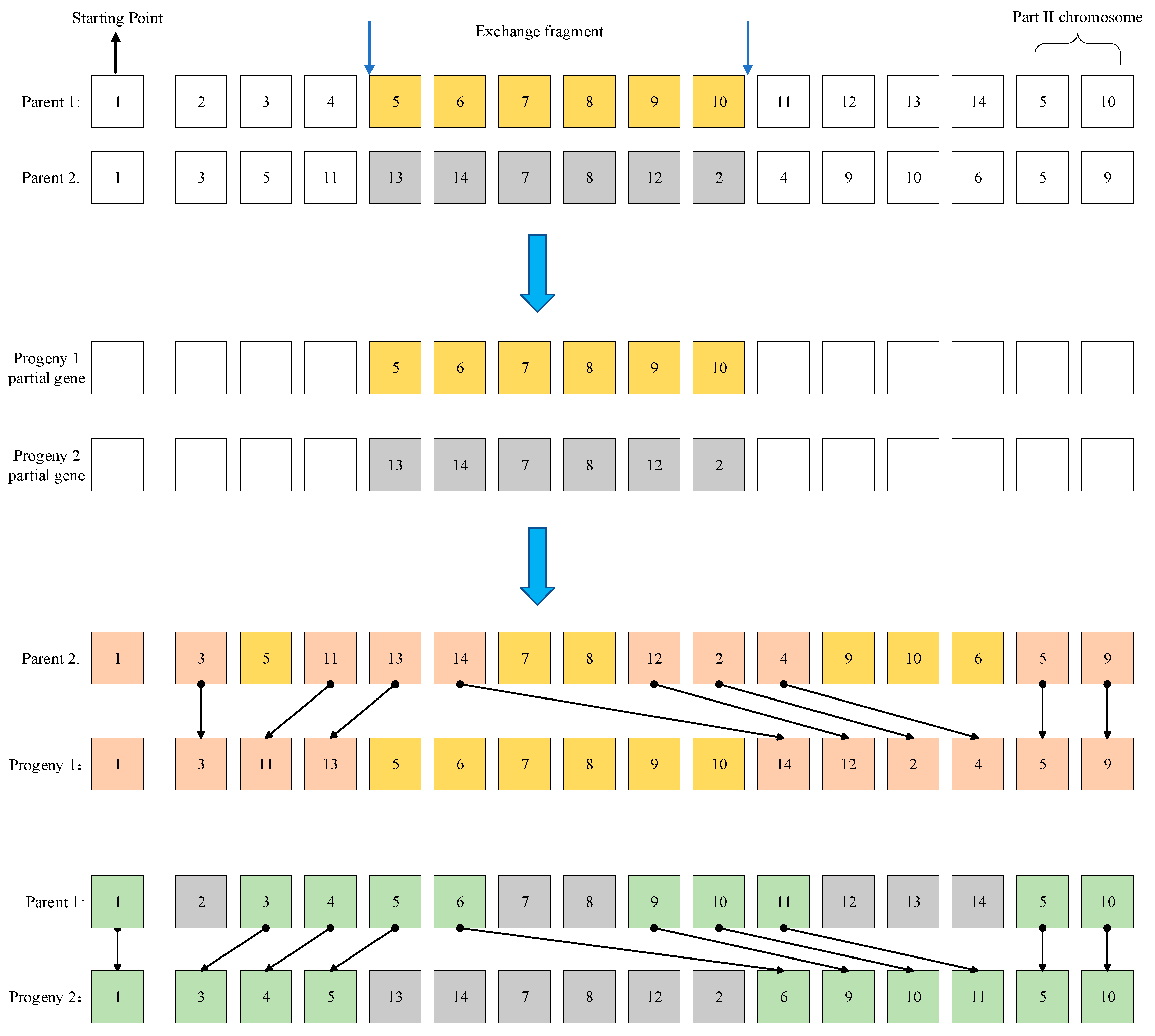
The order cross (OX) and the circular cross (CX) are used for the cross operation and for performing two kinds of cross operations with a certain cross probability Pm during the operation. Respectively, the two crossover operators change the two segments of gene information encoded by individuals in the operation process; that is, the robot task content and task number. The OX is used to copy the continuous exchange gene fragments in a randomly selected pair of parents to the offspring at the same location. Then, the remaining gene information of the parents is placed in the offspring to complete the crossover operation, as shown in Figure 4.
CX is used to copy part of the gene information to the offspring through multiple cyclic operations in two parents. Only one gene can be selected for each crossover in order to realize the crossover and exchange of discontinuous gene information. Then, the remaining gene information of the parent is placed in the offspring to form a new individual to complete the cyclic crossover operation, as shown in Figure 5.
(3) Mutation operation
According to the mutation probability Pm, the mutation operation of the number and sequence of tasks is realized by using the inversion, exchange, and insertion mutations.
The inversion mutation reverses the continuous gene segments (task point execution sequence) of a segment, as shown in Figure 6.
The exchange mutation randomly selects two genes in a chromosome to exchange positions, as shown in Figure 7.
The insertion mutation randomly selects a gene or part of a gene in a chromosome to insert into a random site, as shown in Figure 8.

4.4. Algorithm Implementation

Considering that there are various obstacles in the actual complex scene, the feasible path distance is no longer a linear distance, and the actual energy consumption of the robot may change, resulting in uneven energy consumption. Therefore, the path planning method should be used to achieve obstacle avoidance, recalculate the robot energy consumption, and optimize its task sequence. The current paper uses A* + GA to achieve the goals of energy optimization and energy balance by re-optimizing the task sequence based on the energy penalty strategy without changing the original number of tasks of the robot. The cost function f(n) of the A* algorithm is shown in Equation (7), in which n is the number of task nodes, g(n) is the shortest distance from the start node to the current task node, h(n) is the heuristic function of the shortest path from the current node to the target node.
f n = g n + h n
The main steps of the algorithm are as follows:
Step 1: Set the parameters related to the robot and the task, including number of robots and tasks, energy consumption threshold, energy consumption per unit path, and genetic operation parameters such as population size, genetic probability, iterations. Then, determine the optimal mathematical model and coding mode of the robot energy consumption, in which the energy consumption is calculated by the shortest linear distance between adjacent task nodes;
Step 2: Initialize the individual population to generate the number and sequence of tasks of the robot at a certain scale;
Step 3: Calculate the fitness function value based on the energy penalty mechanism and analyze and compare the energy consumption data of individual populations;
Step 4: Through genetic operation, selection, cross and mutation, select the superior individuals in the current population to generate new individuals and the next generation of population;
Step 5: Repeat Steps (3)~(4) until the iteration termination condition is met and output the optimal solution of the multirobot task assignment and path planning;
Step 6: Based on the requirements of obstacle avoidance, construct the multirobot operation scene while keeping the number of multirobot task nodes unchanged. Then, re-initialize the individual population of the multirobot task sequence;
Step 7: A* algorithm is used to search the optimal planning path under the current task sequence, after which the energy penalty strategy is used to calculate and evaluate the energy consumption target value of the robot;
Step 8: Select the next generation of individual population via genetic operation. Repeat Step (7) until the iteration termination condition is met and output the optimal task sequence and path of the multirobot.

5. Simulation Experiment Analysis

5.1. MRTA Optimization

To prove the effectiveness of the penalty mechanism in the algorithm, the proposed algorithm in this paper is compared with the basic GA through simulation experiments. Assuming that all robots have sufficient initial energy, the initial parameters are set as follows: with energy consumption per unit distance A as a constant value, take A = 1.5 J, α = 4 % , population size M = 80 , P c = 0.8 , P m = 0.1 , and iterations T = 1000 . In addition, the computational characteristics of the computer used for all experiments are as follows: DELL G3 3590, Intel(R) Core(TM) i7-9750H CPU @ 2.60 GHz, 16.0 GM (RAM), and the software is MATLAB R2019a.
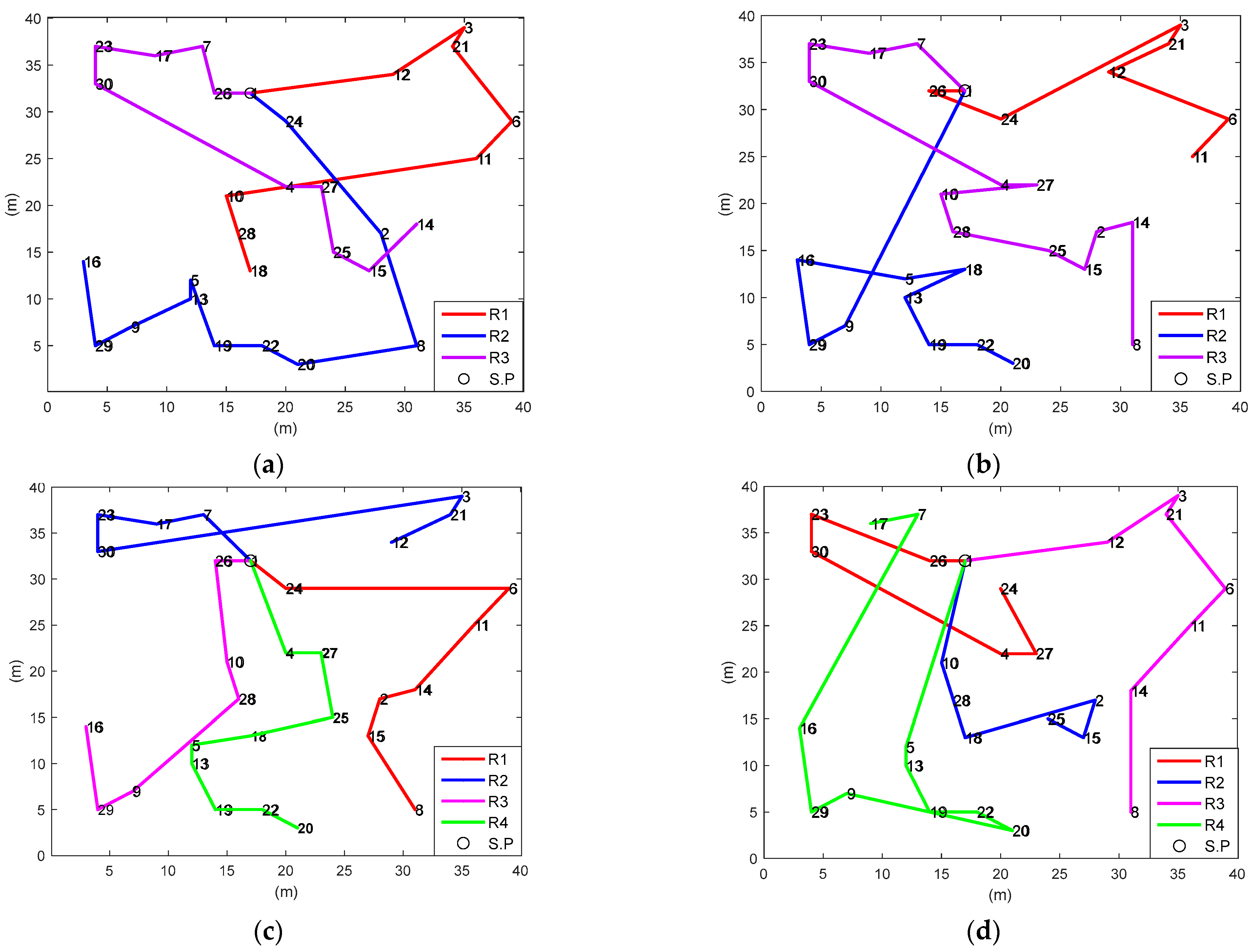
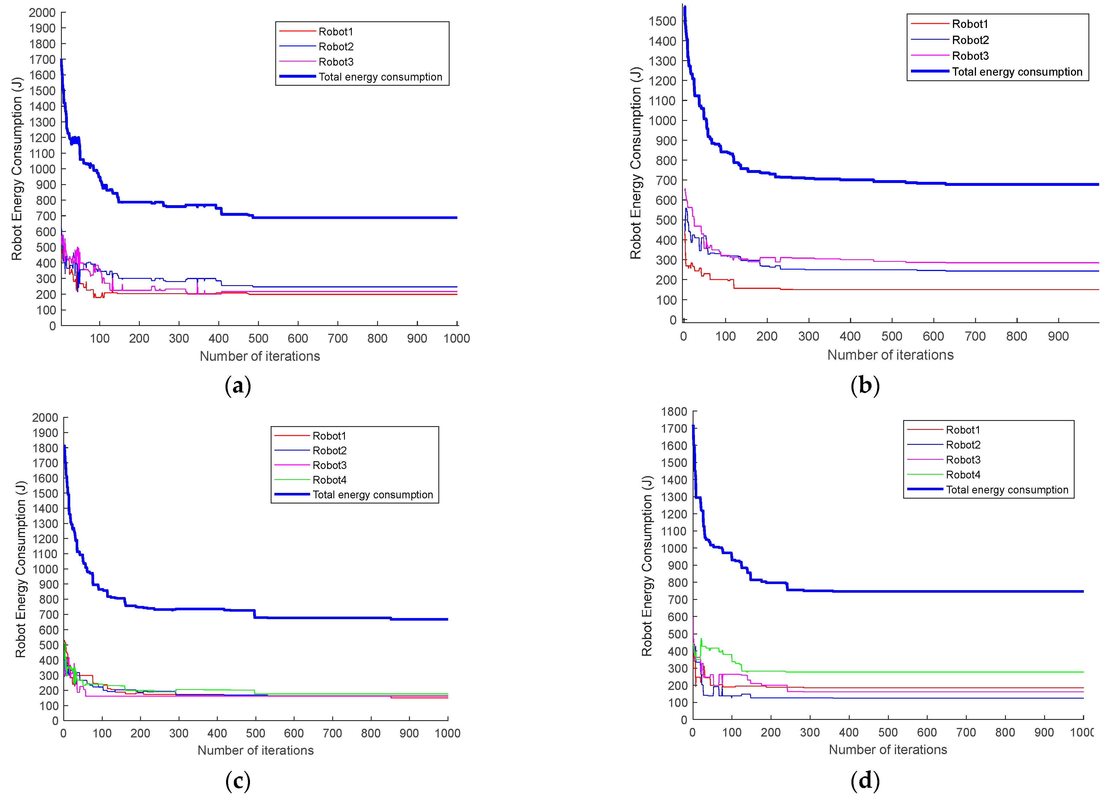
Experiment 1: We set the number of tasks m = 30 (the task nodes are represented by 1~30 serial numbers). When the number of robots is n = 3 and n = 4, the proposed algorithm and the basic GA are used to realize the task planning. Given the same barrier-free task environment, multiple robots begin to perform other tasks from starting point 1 (virtual task point). The simulation diagram of optimal task planning and the iterative curve of robot energy consumption are shown in Figure 9 and Figure 10.
The optimal task sequence (TS) and task number (TN) of the algorithm in this paper (Figure 9a,c, respectively) are shown below.
O p t ( T S ) m = 30 , n = 3 = R 1 : { ( 1 ) , 12 , 3 , 21 , 6 , 11 , 10 , 28 , 18 } , T N 1 = 8 R 2 : { ( 1 ) , 24 , 2 , 8 , 20 , 22 , 19 , 13 , 6 , 9 , 29 , 16 } , T N 2 = 11 R 3 : { ( 1 ) , 26 , 7 , 17 , 23 , 30 , 4 , 27 , 25 , 15 , 14 } , T N 3 = 10
O p t ( T S ) m = 30 , n = 4 = R 1 : { ( 1 ) , 24 , 6 , 11 , 14 , 2 , 15 , 8 } , T N 1 = 7 R 2 : { ( 1 ) , 7 , 17 , 23 , 30 , 3 , 21 , 12 } , T N 2 = 7 R 3 : { ( 1 ) , 26 , 10 , 28 , 9 , 29 , 16 } , T N 3 = 6 R 4 : { ( 1 ) , 4 , 27 , 25 , 18 , 5 , 13 , 19 , 22 , 20 } , T N 4 = 9
It can also be seen from the energy consumption iteration curve of the robot (Figure 10a–d) that the GA of the energy penalty strategy improves the convergence speed of genetic iteration with lower total energy consumption and better energy balance. The experimental data of the robot energy consumption and standard deviation σ are shown in Table 1.
The results indicate that when n = 3 and n = 4, the total energy consumption rates of the proposed algorithm are 2.3% and 12.6% lower than those of the basic GA (without penalty mechanism), and the standard deviations are 65.6% and 83.8% lower, respectively. Therefore, compared with the basic GA (Figure 9b,d), the task allocation of the proposed algorithm (Figure 9a,c) is more reasonable. Furthermore, the task groups are relatively centralized, which ensures the balance of each robot’s movement distance and energy consumption. Thus, genetic optimization based on the energy penalty strategy can not only reduce the total energy consumption but also relatively balance the energy consumption of each robot. Moreover, without changing the number of tasks and the task environment, increasing the number of robots will reduce the total energy consumption by 1.4%, and the standard deviation of energy consumption will be reduced from 23.8 to 10.3; that is, the energy consumption will be more balanced, which means that with the increase of the number of robots, the optimization performance of the algorithm in energy consumption, and energy consumption balance will be more stable and reliable. Comparing the time consumption of obtaining the optimal solution between the two algorithms shows that the basic genetic algorithm is faster because the algorithm in this paper increases the calculation of penalty energy consumption. In addition, the change in the number of robots also affects the calculation time.
Experiment 2: To verify the effectiveness of the algorithm, change the number of tasks m = 40, and the task nodes are represented by 1–40 serial numbers. The simulation diagram of optimal task planning and the iterative curve of robot energy consumption are shown in Figure 11 and Figure 12.
The optimal TS and TN of the algorithm in this paper (Figure 11a,c) are shown below.
O p t ( T S ) m = 40 , n = 3 = R 1 : { ( 1 ) , 13 , 27 , 38 , 28 , 30 , 2 , 14 , 10 , 4 , 33 , 9 , 12 , 19 , 25 } , T N 1 = 14 R 2 : { ( 1 ) , 20 , 35 , 6 , 21 , 3 , 26 , 16 , 31 , 23 , 24 , 22 , 29 , 5 , 18 } , T N 2 = 14 R 3 : { ( 1 ) , 11 , 32 , 17 , 34 , 15 , 8 , 36 , 40 , 37 , 39 , 7 } , T N 3 = 11
O p t ( T S ) m = 40 , n = 4 = R 1 : { ( 1 ) , 3 , 26 , 21 , 17 , 34 , 15 , 8 , 36 , 40 } , T N 1 = 9 R 2 : { ( 1 ) , 13 , 38 , 27 , 32 , 11 , 6 , 35 , 20 , 24 } , T N 2 = 9 R 3 : { ( 1 ) , 2 , 14 , 9 , 12 , 25 , 19 , 18 , 22 , 23 , 31 , 16 } , T N 3 = 11 R 4 : { ( 1 ) , 29 , 5 , 33 , 4 , 10 , 28 , 30 , 39 , 37 , 7 } , T N 4 = 10
When the number of robots increases, similar to the result of Experiment 1, the optimal scheme of the MRTA is more reasonable than the basic GA. It can be seen from the energy consumption iteration curve (Figure 12) that it still has a better effect in terms of convergence speed and energy consumption. The specific experimental parameters are shown in Table 2.
The results show that when the number of tasks is m = 40, the total energy consumption for completing all tasks with the number of robots n = 3 and n = 4 is reduced by 4.2% and 2.5% compared with the basic GA (without penalty mechanism), and the energy standard deviation is reduced by 60.6% and 76.5%, respectively. These findings reveal that the energy penalty strategy can stably maintain the optimal energy consumption and energy balance in genetic iteration. According to the calculation results of Experiments 1 and 2, different initial parameters, such as the number of robots and tasks and the task environment, have little impact on the algorithm performance. Furthermore, the improvement in the algorithm’s robustness is directly proportional to the increase in the number of tasks and robots. The comparison of time is similar to Experiment 1 and increases as the number of tasks increases.
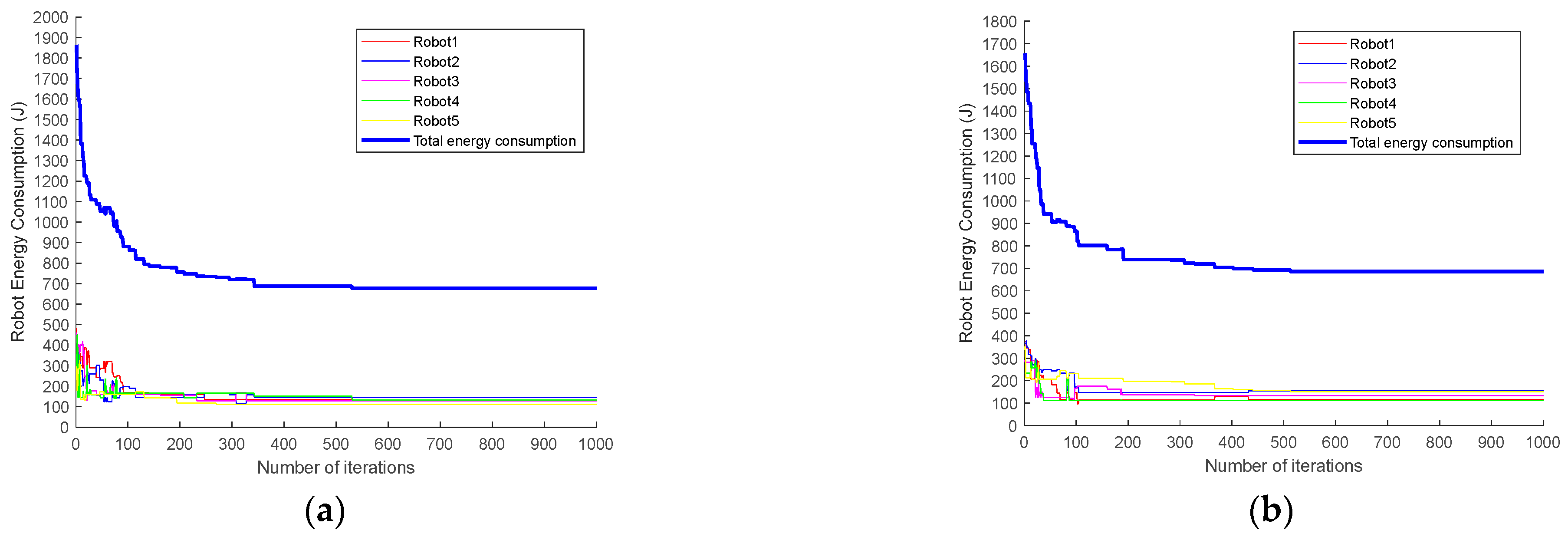
Experiment 3: To compare the algorithm performance difference between this paper and the penalty function and genetic algorithm in [34], we set the number of tasks m = 30 and the number of robots n = 5 and conducted simulation experiments under the same genetic parameter settings. The comparison of energy consumption iteration curves is shown in Figure 13.
It can be intuitively seen in the figure that the total energy consumption of the algorithm in this paper is smaller in the stable iteration stage (after about 300 iterations) and that the energy consumption curve of each robot is more concentrated. The specific operation parameters are shown in Table 3.
The experimental data reveal that, compared with the algorithm in [34], the total energy consumption of the algorithm in the current work is reduced by 0.3%, and the standard deviation is also reduced by 29.6%. This indicates that the performance of the proposed algorithm is better than that of the basic GA. Therefore, the energy penalty strategy is effective and feasible in ensuring optimal and balanced energy consumption.

5.2. Task Sequence Optimization of A* + GA

In the two task environments of regular obstacles and irregular obstacles, the A* algorithm is used to plan the obstacle avoidance path between adjacent task nodes without changing the number of tasks. It is also used to recalculate and evaluate the robot energy consumption as well as to realize the secondary optimization of the energy excess robot task sequence through genetic iteration.
Experiment 4: We set a regular obstacle environment map and ensure that the distribution of task points is the same as that in Experiment 2. The number of tasks m = 40, the number of robots n = 3, and the size of the grid map is 80 × 80 m. The A* optimal path planning diagram before task sequence optimization is shown in Figure 14.
As shown in Table 4, the relative error of energy consumption of Robot 2 P2 = 5.56%, which exceeds the threshold α = 4 % . Therefore, it is necessary to re-optimize the task sequence of Robot 2 to minimize its energy consumption. The optimized optimal path planning diagram of Robot 2 (renamed as “Robot 2a”) based on the GA is shown in Figure 15. Meanwhile, the respective task sequences and related experimental data of Robot 2 before and after optimization are shown in Table 5.
It can be seen that the path length of the optimized Robot 2 is reduced by 3.4%, and the energy consumption is reduced by 2.2%. As shown in Table 6, the total energy after task sequence optimization is 0.78% lower than the previous one, and the standard deviation is also 13.85% lower. Therefore, the results indicate the effectiveness of the proposed algorithm.
Experiment 5: Here, we set the irregular obstacle environment map, the number of tasks m = 30, and the number of robots n = 3. Furthermore, the distribution of task points is the same as that in Experiment 1, and the grid map size is 40 m × 40 m. The A* optimal path planning diagram before task sequence optimization is shown in Figure 16.
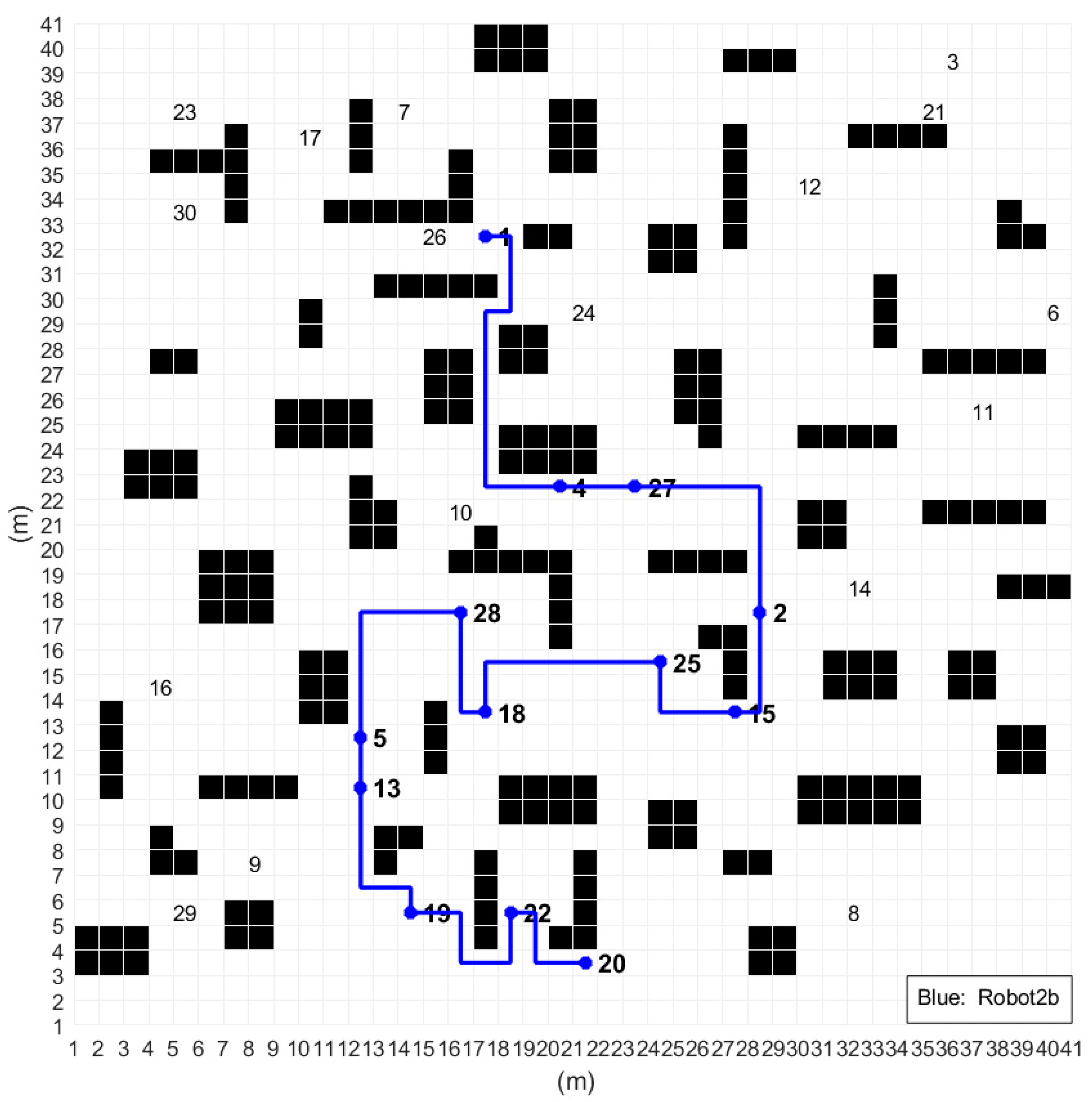
As shown in Table 7, the relative error of energy consumption of Robot 2 P2 = 10.71%, which exceeds the threshold α = 4 % . Thus, the task sequence of Robot 2 should be re-optimized. The optimized optimal path planning of Robot 2 (renamed as “Robot 2b”) is shown in Figure 17. The respective task sequences and experimental parameters of Robot 2 before and after optimization are shown in Table 8.
As shown in Table 8, the path length of the optimized Robot 2 is reduced by 18.6%, and the energy consumption is reduced by 17.4%. In Table 9, the total energy after task sequence optimization is 6.41% lower than the previous one, and the standard deviation is also 51.58% lower.
The analysis of the results of Experiments 4 and 5 indicates that the task sequence optimization process using A* + GA can effectively reduce energy consumption and maintain energy balance in different task scenarios. Notably, in order to reduce the amount of computation, the second stage of the proposed algorithm optimizes the task sequence of the robot with a high energy consumption only on the basis of not changing the number of tasks. Other robot task sequences with low energy consumption do not need to be recalculated.

6. Conclusions

To address the problem of multirobot task planning, an MRTA method based on the energy penalty strategy is proposed, which targets the twofold objective of minimizing energy consumption and increasing energy balance acting on task number and task sequence. The first stage of the algorithm calculates the energy consumption of the robot with the shortest linear distance between adjacent task nodes in the barrier-free task environment. Then, it reconstructs the energy penalty objective function with the total energy consumption and penalty energy, after which it iteratively calculates the optimal scheme of multitask allocation through genetic operators to achieve the dual goals of total energy consumption optimization and energy balance. The results from experiment 1, 2, and 3 highlight a significant improvement in energy consumption and energy balance compared with the basic GA and related literature algorithms.
The second stage of the algorithm is to form a complex task scenario by adding rules and irregular obstacles in the task environment of the previous stage. The distance between adjacent task nodes and their energy consumption will change due to the path obstacle avoidance requirements of the complex scenario. Thus, it is necessary to recalculate and optimize the optimal task allocation scheme of the first stage. The A* algorithm is then used to obtain the optimal path for obstacle avoidance and calculate the energy consumption. On the premise of not changing the number of robot tasks, the GA is used again to optimize the robot task sequence with excessive energy consumption. Experiments 4 and 5 were conducted in two different scenarios (regular and irregular obstacle distribution, respectively), and the results indicate the effectiveness of the algorithm. Furthermore, the energy penalty strategy plays a driving role in iterative optimization in task planning. The strategy can also be combined with other optimization algorithms for implementation verification in different application environments.
The algorithm proposed in this paper is implemented in stages according to the change in the task environment, especially in the second stage, where the task sequence is re-optimized without changing the number of tasks; therefore, it is relatively simple and feasible and can be used to solve large-scale optimization problems. Furthermore, the algorithm model can also adjust the size of the punishment by setting the penalty factor and its change to further study the rationality of the punishment strategy. Given that the second stage of the algorithm is only secondary optimization for the task sequence of the robot with excessive energy consumption, the search space can be extended to all robots. This is also the direction of forthcoming research.

Author Contributions

Conceptualization, L.L. and L.Z.; methodology, L.L. and W.J.; software, L.Z.; validation, L.L., L.L. and W.J.; formal analysis, L.L. and L.Z.; investigation, X.C.; resources, L.L.; data curation, L.L. and L.Z.; writing—original draft preparation, L.L. and L.Z.; writing—review and editing, L.L. and L.Z.; visualization, L.L. and L.Z.; supervision, X.C.; project administration, L.L.; funding acquisition, L.L. All authors have read and agreed to the published version of the manuscript.

Funding

This research was funded by the Key Project of Natural Science of Anhui Provincial Department of Education (Project ID. KJ2018A0102, 2022AH050992), and the Anhui Institute of Future Technology enterprise cooperation project (Project ID. None).

Institutional Review Board Statement

Not applicable.

Informed Consent Statement

Not applicable.

Data Availability Statement

Please contact the first author: [email protected].

Conflicts of Interest

The authors declare no conflict of interest.

Abbreviations

The following abbreviations are used in this manuscript:
MRTA Multirobot task allocation
TSP  Traveling Salesman Problem
MTSP Multiple Traveling Salesman Problem
VRP  Vehicle Routing Problem
GA Genetic Algorithm
PE  Penalty Energy
OX Order Cross
CX Circular Cross
A* A-STAR
TS  Task Sequence
TN  Task Number

References

  1. Zhang, F.; Lin, L. Architecture and Related Problems of Multi-Mobile Robot Coordination System. Robots 2001, 23, 554–558. [Google Scholar]
  2. Zhang, Z.; Gong, S.; Xu, D.; Meng, Y.; Li, X.; Feng, G. Multi-Robot Task Assignment and Path Planning Algorithm. J. Harbin Eng. Univ. 2019, 40, 1753–1759. [Google Scholar]
  3. Xiong, Q.; Dong, C.; Hong, Q. Multi-robot Task Allocation Method for Raw Material Supply Link in Intelligent Factory. Minicomicter Syst. 2022, 43, 1625–1630. [Google Scholar]
  4. Lei, B.; Jin, Y.; Wang, Z.; Zhao, R.; Hu, F. Present Situation and Development of Warehouse Logistics Robot Technology. Mod. Manuf. Eng. 2021, 12, 143–153. [Google Scholar]
  5. Song, W.; Gao, Y.; Shen, L.; Zhang, Y. A Task Allocation Algorithm for Multiple Robots Based on Near Field Subset Partitioning. Robots 2021, 43, 629–640. [Google Scholar]
  6. Xu, S.; Wang, Z. Research Progress and Key Technologies of Fire Rescue Multi-Robot System. Sci. Technol. Innov. Appl. 2022, 12, 155–157+161. [Google Scholar]
  7. Siwek, M.; Panasiuk, J.; Baranowski, L.; Kaczmarek, W.; Prusaczyk, P.; Borys, S. Identification of Differential Drive Robot Dynamic Model Parameters. Materials 2023, 16, 683. [Google Scholar] [CrossRef] [PubMed]
  8. Zhou, Z.; Zhu, P.; Zeng, Z.; Xiao, J.; Lu, H.; Zhou, Z. Robot navigation in a crowd by integrating deep reinforcement learning and online planning. Appl. Intell. 2022, 52, 15600–15616. [Google Scholar] [CrossRef]
  9. Fox, D.; Ko, J.; Konolige, K.; Limketkai, B.; Schulz, D.; Stewart, B. Distributed Multirobot Exploration and Mapping. Proc. IEEE 2006, 94, 1325–1339. [Google Scholar] [CrossRef]
  10. Vasconcelos, J.V.R.; Brandão, A.S.; Sarcinelli-Filho, M. Real-Time Path Planning for Strategic Missions. Appl. Sci. 2020, 10, 7773. [Google Scholar] [CrossRef]
  11. Hart, P.E.; Nilsson, N.J.; Raphael, B. A Formal Basis for the Heuristic Determination of Minimum Cost Paths. IEEE Trans. Syst. Sci. Cybern. 1968, 4, 100–107. [Google Scholar] [CrossRef]
  12. Chaimowicz, L.; Sugar, T.; Kumar, V.; Campos, M.F.M. An Architecture for Tightly Coupled Multi-Robot Cooperation. In Proceedings of the 2001 ICRA IEEE International Conference on Robotics and Automation (Cat. No. 01CH37164), Seoul, Republic of Korea, 21–26 May 2001; Volume 3, pp. 2992–2997. [Google Scholar]
  13. Liu, C.; Kroll, A. A Centralized Multi-Robot Task Allocation for Industrial Plant Inspection by Using A* and Genetic Algorithms. In Proceedings of the 11th International Conference on Artificial Intelligence and Soft Computing, Zakopane, Poland, 29 April–3 May 2012. [Google Scholar]
  14. Turner, J.; Meng, Q.; Schaefer, G.; Whitbrook, A.; Soltoggio, A. Distributed Task Rescheduling with Time Constraints for the Optimization of Total Task Allocations in a Multirobot System. IEEE Trans. Cybern. 2018, 48, 2583–2597. [Google Scholar] [CrossRef] [PubMed] [Green Version]
  15. Zlot, R.; Stentz, A. Complex Task Allocation for Multiple Robots. In Proceedings of the IEEE International Conference on Robotics and Automation (ICRA), Barcelona, Spain, 18–22 April 2005; pp. 1515–1522. [Google Scholar]
  16. Luo, L.; Chakraborty, N.; Sycara, K. Provably-Good Distributed Algorithm for Constrained Multi-Robot Task Assignment for Grouped Tasks. IEEE Trans. Robot. 2015, 31, 19–30. [Google Scholar] [CrossRef]
  17. Odili, J.B.; Noraziah, A.; Sidek, R.M. Swarm Intelligence Algorithms’ Solutions to the Travelling Salesman’s Problem. IOP Conf. Ser. Mater. Sci. Eng. 2020, 769, 1–10. [Google Scholar] [CrossRef]
  18. Jin, L.; Li, S.; La, H.M.; Zhang, X.; Hu, B. Dynamic Task Allocation in Multi-Robot Coordination for Moving Target Tracking: A distributed approach. Automatica 2019, 100, 75–81. [Google Scholar] [CrossRef]
  19. Jiang, G.; Lam, S.; Ning, F.; He, P.; Xie, J. Peak-Hour Vehicle Routing for First-Mile Transportation: Problem Formulation and Algorithms. IEEE Trans. Intell. Transp. Syst. 2020, 21, 3308–3321. [Google Scholar] [CrossRef]
  20. Al-Dulaimi, B.F.; Ali, H.A. Enhanced Traveling Salesman Problem Solving by Genetic Algorithm Technique (TSPGA). Int. J. Math. Comput. Sci. 2008, 2, 123–129. [Google Scholar]
  21. Zhang, C.; Zhou, Y.; Li, Y. Review of Multi-Robot Collaborative Navigation Technology. Unmanned Syst. Technol. 2020, 13, 26–34. [Google Scholar]
  22. Yuan, Q.; Yi, G.; Hong, B.; Meng, X. Multi-Robot Task Allocation Using CNP Combines with Neural Network. Neural Comput. Appl. 2013, 23, 1909–1914. [Google Scholar] [CrossRef]
  23. Cao, R.; Li, S.; Ji, Y.; Xu, H.; Zhang, M.; Li, M. Task Planning of Multi-Machine Cooperative Work Based on Ant Colony Algorithm. Trans. Agric. Mach. Soc. 2019, 50, 34–39. [Google Scholar]
  24. Shuai, H.; Huang, Z.; Wang, L.; Rui, Z.; Yu, W. An Optimal Task Decision Method for a Warehouse Robot with Multiple Tasks Based on Linear Temporal Logic. In Proceedings of the 2017 IEEE International Conference on Systems, Man and Cybernetics (SMC), Banff, AB, Canada, 5–8 October 2017; pp. 1453–1458. [Google Scholar]
  25. Yi, Z.; Wang, F.; Fu, F.; Su, Z. Multi-AGV Path Planning for Indoor Factory by Using Prioritized Planning and Improved Ant Algorithm. J. Eng. Technol. Sci. 2018, 50, 534–547. [Google Scholar]
  26. Weerakoon, T.; Ishii, K.; Nassiraei, A. An Artificial Potential Field Based Mobile Robot Navigation Method to Prevent from Deadlock. J. Artif. Intell. Soft Comput. Res. 2015, 5, 189–203. [Google Scholar] [CrossRef] [Green Version]
  27. Tuazon, J.; Prado, K.; Cabial, N.; Enriquez, R.; Rivera, F.; Serrano, K. An Improved Collision Avoidance Scheme Using Artificial Potential Field with Fuzzy Logic. In Proceedings of the 2016 IEEE Region 10 Conference (TENCON), Singapore, 22–25 November 2016; pp. 291–296. [Google Scholar]
  28. Zhang, D.; Sun, X.; Fu, S.; Zheng, B. Multi-Robot Collaborative Path Planning Method in Intelligent Warehouse. Comput. Integr. Manuf. Syst. 2018, 24, 410–418. [Google Scholar]
  29. Yuan, Y.; Ye, F.; Lai, Y.; Zhan, Y. Multi-AGV Path Planning Combined with Load Balancing and A* Algorithm. Comput. Eng. Appl. 2020, 56, 251–256. [Google Scholar]
  30. Zhao, J.; Zhang, Y.; Ma, Z. Improvement and Validation of A-Star Algorithm for AGV Path Planning. Comput. Eng. Appl. 2018, 54, 222–228. [Google Scholar]
  31. Zhang, Y.; Tan, Z.; Zhou, W.; Fang, D. Research on Stochastic Path Optimization Based on Shortest Distance Fitness. Intell. Comput. Appl. 2021, 11, 153–156. [Google Scholar]
  32. Wu, Y.; Jiang, L.; Liu, Q. Multi-Travel Salesman Problem Solving Based on Parallel Genetic Algorithm. Microcomput. Appl. 2011, 27, 45–47+71. [Google Scholar]
  33. Yu, D.; Yang, Y. Optimal Genetic Algorithm for Emergency Rescue Vehicle Scheduling at multiple disaster Sites. Comput. Syst. Appl. 2016, 25, 201–207. [Google Scholar]
  34. Gao, X.; Huang, D.; Ding, S. PID Parameter Optimization Based on Penalty Function and Genetic Algorithm. J. Jilin Inst. Chem. Technol. 2021, 38, 57–60. [Google Scholar]
  35. Zhu, G. C++ Implementation of Genetic Algorithm and Roulette Choice. J. Dongguan Univ. Technol. 2007, 14, 70–74. [Google Scholar]
Figure 1. Task planning algorithm framework based on energy penalty.
Applsci 13 04887 g001
Figure 2. Two-segment chromosome coding format.
Applsci 13 04887 g002
Figure 3. Coding representation of m = 14, n = 3.
Applsci 13 04887 g003
Figure 4. Order cross operation (m = 14).
Applsci 13 04887 g004
Figure 5. Circular cross operation (m = 14).
Applsci 13 04887 g005
Figure 6. Inversion mutation operation (m = 14).
Applsci 13 04887 g006
Figure 7. Exchange mutation operation (m = 14).
Applsci 13 04887 g007
Figure 8. Insertion mutation operation (m = 14).
Applsci 13 04887 g008
Figure 9. Multirobot optimal task allocation diagram from Experiment 1: (a) algorithm in this paper (m = 30, n = 3); (b) basic genetic algorithm (m = 30, n = 3); (c) algorithm in this paper (m = 30, n = 4); (d) basic genetic algorithm (m = 30, n = 4).
Applsci 13 04887 g009
Figure 10. Iterative curve of robot energy consumption from Experiment 1: (a) algorithm in this paper (m = 30, n = 3); (b) basic genetic algorithm (m = 30, n = 3); (c) algorithm in this paper (m = 30, n = 4); (d) basic genetic algorithm (m = 30, n = 4).
Applsci 13 04887 g010
Figure 11. Multirobot optimal task allocation diagram from Experiment 2: (a) algorithm in this paper (m = 40, n = 3); (b) basic genetic algorithm (m = 40, n = 3); (c) algorithm in this paper (m = 40, n = 4); (d) basic genetic algorithm (m = 40, n = 4).
Applsci 13 04887 g011
Figure 12. Iterative curve of robot energy consumption in Experiment 2: (a) algorithm in this paper (m = 40, n = 3); (b) basic genetic algorithm (m = 40, n = 3); (c) algorithm in this paper (m = 40, n = 4); (d) basic genetic algorithm (m = 40, n = 4).
Applsci 13 04887 g012
Figure 13. Iterative curve of robot energy consumption from experiment 3: (a) algorithm in this paper; (b) penalty function and genetic algorithm.
Applsci 13 04887 g013
Figure 14. A* algorithm path planning diagram of the initial task sequence from Experiment 4.
Applsci 13 04887 g014
Figure 15. Path planning diagram of Robot 2 after task sequence optimization from Experiment 4.
Applsci 13 04887 g015
Figure 16. A* algorithm path planning diagram of the initial task sequence from Experiment 5.
Applsci 13 04887 g016
Figure 17. Path planning diagram of Robot 2 after task sequence optimization from Experiment 5.
Applsci 13 04887 g017
Table 1. Comparison of algorithm parameters from Experiment 1.
m = 30, n = 3
AlgorithmE(R1) (J)E(R2) (J)E(R3) (J)Sum(E) (J) σ T (s)
This paper199.2246.4217.1662.723.810.4
Basic GA150.0243.4285.1678.569.27.6
m= 30, n = 4
AlgorithmE(R1) (J)E(R2) (J)E(R3) (J)E(R4) (J)Sum(E) (J) σ T (s)
This paper151.3164.6160.9176.3653.110.311.5
Basic GA184.6124.0161.5276.9747.065.19.7
Table 2. Comparison of algorithm parameters from Experiment 2.
m = 40, n = 3
AlgorithmE(R1) (J)E(R2) (J)E(R3) (J)Sum(E) (J) σ T (s)
This paper657.6 743.7732.8 2134.146.919.2
Basic GA762.3614.9850.42227.6119.016.4
m = 40, n = 4
AlgorithmE(R1) (J)E(R2) (J)E(R3) (J)E(R4) (J)Sum(E) (J) σ T (s)
This paper632.3570.1558.0568.02328.433.926.3
Basic GA453.1528.8608.0797.12387.0147.822.6
Table 3. Comparison of algorithm parameters from Experiment 3.
AlgorithmE(R1) (J)E(R2) (J)E(R3) (J)E(R4) (J)E(R5) (J)Sum€ (J) σ T (s)
This paper146.0145.0128.3132.8112.2664.313.813.6
Paper [34]115.3155.2133.0112.2150.4666.119.615.4
Table 4. Path planning operation parameters of A* algorithm from Experiment 4.
Robot No.L(R) (m)E (R)P (%)
Robot1202840.75-
Robot2232957.455.56%
Robot3186922.951.75%
Table 5. The optimal task sequence and operation parameters of Robot 2 from Experiment 4.
Task
Optimization
TS(R2) L(R2) (m)E(R2) (J)
Before {(1),20,35,6,21,3,26,16,31,23,24,22,29,5,18}232957.45
After {(1),29,20,35,6,21,3,26,16,31,23,24,22,5,18}224936.15
Table 6. Comparison of energy consumption before and after optimization from Experiment 4.
Task
Optimization
E(R1) (J)E(R2) (J)E(R3) (J)Sum(E) (J) σ
Before 840.75957.45922.952721.1560.0
After 840.75936.15922.952699.8551.69
Table 7. Path planning operation parameters of A* algorithm from Experiment 5.
Robot No.L(R) (m)E(R)P (%)
Robot186307.80-
Robot2102343.0510.71%
Robot391278.70-
Table 8. The optimal task sequence and operation parameters of Robot 2 from Experiment 5.
Task
Optimization
TS(R2) L(R2) (m)E(R2) (J)
Before {(1),2,25,15,20,22,19,13,5,18,28,4,27}102343.05
After {(1),4,27,2,15,25,18,28,5,13,19,22,20}83283.50
Table 9. Comparison of energy consumption before and after optimization from Experiment 5.
Task
Optimization
E(R1)E(R2)E(R3)Sum(E) (J) σ
Before 307.80343.05278.70929.5532.22
After 307.80283.50278.70870.0015.60
Disclaimer/Publisher’s Note: The statements, opinions and data contained in all publications are solely those of the individual author(s) and contributor(s) and not of MDPI and/or the editor(s). MDPI and/or the editor(s) disclaim responsibility for any injury to people or property resulting from any ideas, methods, instructions or products referred to in the content.