Abstract
Aiming at the problem of the coexistence of matching and mismatching uncertainties in electro-hydraulic servo systems, disturbance observers and a backstepping sliding mode controller based on the generalized super-twisting algorithm (GSTA) are proposed in this paper. First, in order to compensate for the uncertainty in the controller, two generalized super-twisting disturbance observers (GSTDOs) are constructed to effectively reduce the discontinuous gain of the controller. Then, the GSTA is introduced to optimize the backstepping sliding mode controller to obtain a better control effect. Finally, the proposed control strategy is compared and simulated on the electro-hydraulic servo system. The experimental results verify that the proposed control strategy has better tracking performance. The effect of asymptotic tracking in the presence of parameter uncertainties and disturbances is achieved, while transient tracking performance and final tracking accuracy are guaranteed in the presence of time-varying uncertain nonlinearities.
1. Introduction
Electro-hydraulic servo systems are characterized by high power, rapid action and accurate responses. This kind of scheme is one of the core technologies of mechanical and electronic engineering. It is used on a large scale in aircraft manufacturing [1], robotic motion devices [2] and industrial robots [3]. Additionally, there are some problems in the control process, because electro-hydraulic servo systems have nonlinearity and uncertainty [4]. Therefore, some aspects of system modeling and control methods are worth studying, such as leakage [5], which will affect the control ideality of systems. In [6], the first result of the stabilization of electro-hydraulic servo systems is presented for nonlinear models without any linearization. Due to the complex working environments, traditional controllers often fail to meet their control accuracy and performance requirements. With the continuous improvement of the technology level, the control accuracy and anti-interference ability of electro-hydraulic servo systems have put forward higher requirements.
With the development of electro-hydraulic servo systems with a high precision, high frequency response, wide speed range, strong anti-interference ability and great reliability, the improvement of performance becomes more and more important. The stability of nonlinear systems [7] and tracking problems [8] have always been highly valued in the field of control. The most widely used in practice is proportional integral derivative (PID) control and its improved algorithm. PID control is applied because of its simple structure. For example, in [9], a PID controller based on coupling and hybrid fuzzy is designed for the control of hydraulic systems, which successfully combined fuzzy logic. In [10], a fractional order PID controller is designed, which achieves a better tracking effect than the traditional PID controller and solves the problem of improving the control accuracy of systems. However, due to the parameter uncertainty, time-varying disturbance, nonlinear friction, serious disturbance, periodic disturbance and so on, the high performance requirements of the systems cannot be satisfied by the control method based on linear theory [11]. Nonlinear control methods such as feedback stabilization [6], backstepping control, sliding mode control (SMC) and robust control [12] are gradually applied.
Backstepping control is a recursive design method that can deal with the nonlinear systems. Backstepping control decomposes complex nonlinear systems into subsystems. Then, the Lyapunov function and virtual control quantity are designed, respectively, and the whole control law is finally obtained [13]. It is widely used in the motion control of electro-hydraulic servo systems. When the disturbance or uncertainty does not meet the matching conditions, the backstepping method has obvious advantages. For example, in [14], an output position backstepping control method for electro-hydraulic systems combined with an extended state observer (ESO) is proposed, which can be accurately evaluated by the boundary of load disturbance. In [15], a filter based on attenuation is designed to reprocess the load and virtual control, which avoids the complexity of the differential in the backstepping method. In [16], the backstepping method is upgraded based on adaptiveness. The controller is combined with digital technology to solve the system tracking problem under state and input constraints. In [17], the problem of a large communication burden is solved by combining backstepping control with dynamic event triggering. In [18], a backstepping method based on a new finite-time filter is proposed to solve the complex nonlinear, noise and disturbance problems in control. In [19], a model-based adaptive backstepping controller is designed to accurately track the synthesized trajectory. However, the disadvantage of backstepping control is the need to perfectly eliminate the nonlinearity in system dynamics, which indicates that it needs to be accurately understood.
Aiming at the uncertainty problem in electro-hydraulic servo systems, SMC has been widely used in recent years. SMC is effective in dealing with uncertain dynamic systems and can improve the robustness of systems [20]. In [21], a closed-loop global fast terminal SMC is designed. The problem of the slow convergence speed of SMC when the error signal is not close to balance is solved. In [22], an SMC for a hydraulic excavator is proposed, which solves the problem of dead time compensation in hydraulic systems. In addition, there are many articles studying the sliding mode. On the basis of the sliding mode, some scholars have introduced the concept of backstepping in SMC. For example, in [23], an SMC based on incomplete differential and improved backstepping is proposed, which achieves the effect of friction compensation. In [24], a control scheme combining the sliding mode with backstepping and adding finite time is proposed to improve the robustness of the system. In [25], an SMC based on adaptiveness and backstepping is proposed, which significantly improved the tracking speed and load dynamic response of systems. The introduction of backstepping sliding mode control expands the scope of application of backstepping control and makes the system robust to interference.
In practice, some physical quantities in electro-hydraulic servo systems cannot be measured directly. Therefore, many scholars have introduced the observer in the control. The basic idea of a nonlinear disturbance observer (NDO) is to observe the equivalent disturbance and compensate for it in the control so as to suppress the disturbance. In [26], the combination of adaptive control and ESO is designed to eliminate the interference of most parameter uncertainties. It also avoids high-gain feedback and improves tracking performance. In [27], a disturbance observer is designed for the flexible actuator model of the servo valve and fluid dynamics. This solves the problem of compensating for the friction effect and model uncertainty. In [28], an extended state observer is designed to observe the state variables and obtain the estimated value of the unknown term. In [29], the disturbance observer and neural network are designed to solve the disturbance and uncertainty. In [30], an observer based on the high-gain sliding mode is proposed, which shows more reliable performance when there is a large external disturbance. The above observers are proposed to solve the estimation of lumped disturbance, but there is still room for improvement in the convergence speed of observation errors.
Therefore, on this basis, the super-twisting algorithm (STA) is introduced [31]. In [32], an SMC based on STA and backstepping is proposed to solve the control problem of systems with compound disturbances. In [33], based on the STA, a new variable integral SMC structure is proposed. It not only overcomes the instability of systems in fast motion but also eliminates the adverse effects of systems themselves. The introduction of the STA has led to the further development of sliding mode control. However, the STA can only deal with the interference that satisfies the Lipschitz continuous condition but cannot solve the uncertain interference that changes with the state. Some scholars have proposed a GSTA, which can simultaneously deal with the interference that satisfies the Lipschitz continuous condition and the uncertainty that changes with the state. Further reducing systems chattering and overshoot improves the response speed and anti-disturbance ability. However, the STA and the GSTA only estimate the matched uncertainty in the application of observers, and the use of mismatched uncertainty is limited. Therefore, in this paper, the GSTA is considered to be introduced into the controller and the estimation of mismatched uncertainties.
This paper introduces the GSTA into the disturbance observer and backstepping controller. Different from other disturbance observer-based controllers, this paper also solves mismatched disturbances in addition to solving matched disturbances, which improves the control accuracy. At the same time, it improves the backstepping sliding mode controller, which accelerates the speed of systems reaching the sliding mode surface in limited time. The matched uncertainty and mismatched uncertainty are estimated by constructing two GSTDOs. The disturbance is compensated for by the GSTDOs in real time. Considering the parameter uncertainty and nonlinear factors in electro-hydraulic servo systems, a backstepping sliding mode controller is designed to precisely control electro-hydraulic servo systems according to the obtained disturbance values and state quantities. A control algorithm combining backstepping and the generalized super-twisting sliding mode is proposed to improve the robustness of systems and achieve the effect of asymptotic tracking.
The remainder of this paper is formatted as follows. The nonlinear model of electro-hydraulic servo systems is introduced in Section 2. The design process and theoretical results of GSTDOs and the backstepping generalized super-twisting controller are presented in Section 3. The experimental outcomes are contrasted in Section 4. Finally, some concluding remarks are delineated in Section 5.
2. Mathematical Models of Systems
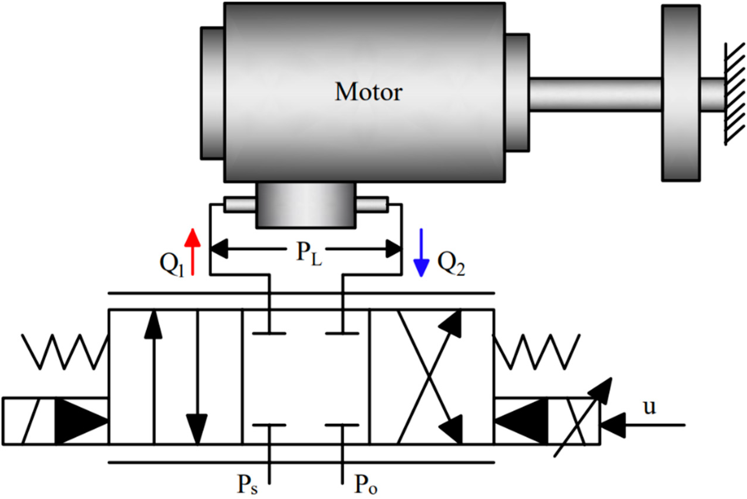
With the continuous development and progress of industrial technology, high-performance electro-hydraulic servo systems are urgently needed as support. This system is selected as the subject of study, without losing generality, as illustrated in Figure 1. It is a typical servo valve-controlled hydraulic motor for rotary actuators. The liquid pressure is its power source, which makes the output shaft rotate. Through advanced control algorithms, the variation in the system input can be automatically, quickly and accurately reproduced by the position of the motor.

Figure 1.
Electro-hydraulic servo systems model.
To better reflect the intrinsic physical parameters of the nonlinear system, the system servo performance must be improved. Without surrendering generality, the servo system is simplified, and the following assumptions are made:
Assumption 1.
The loss in the pipeline can be ignored; the pressure of each working oil chamber is equal everywhere; every leakage is laminar flow.
The nonlinear model of electro-hydraulic servo systems is established. The servo valve flow equation is
where is the pinhole throttling coefficient, is the area gradient, is the pressure of the oil source, is the load pressure and , where and are the two chamber pressures of the oscillating motor, and is oil density. The expression of the sign function is
The equation of the continuity of the flow can be expressed as
where is the global oil leakage coefficient, is the global uncertain leakage, is the displacement of the oscillating motor, is the rotation angle, is the total volume, and is the effective bulk modulus.
The equilibrium equation can be determined using Newton’s second law and is as follows:
where is the rotational inertia, is the external disturbance, is the viscous damping coefficient.
Servo valve is a crucial component of a hydraulic control system with high precision and a fast response. It converts a low-power electrical signal input into a high-power hydraulic energy output to achieve the displacement, speed, acceleration and force control of the actuator. Bandwidth is an index for measuring the dynamic performance of the servo valve, which is related to the response speed of servo systems. In this paper, the servo valve with a high response is used [34]. The servo valve has a high frequency bandwidth, so its dynamics are rewritten as a proportional link as follows [35]:
where is the dynamic proportionality factor and is the control input.
Accordingly, the servo valve flow equation can be obtained as
where is the total flow gain.
Selecting the state variables as , then the state space expression can be obtained as follows:
where , , , , .
Assumption 2.
The mismatched uncertainty and the matched uncertainty are bounded as follows:
where and are known positive constants.
3. Controller Design
3.1. Generalized Super-Twisting Disturbance Observers
Based on the model (6), two GSTDOs are constructed to estimate mismatched uncertainty and matched uncertainty, respectively.
For the mismatched uncertainty, the errors are defined as
where and are the observed values of and , respectively.
The GSTDO is designed to
where and are positive constants, is the gain of the observer, and and are nonlinear stabilization terms, expressed as follows:
where and are nonnegative constants and are not zero at the same time, and is a real number. and are related and monotone increasing functions of ; since , is continuous while is discontinuous at .
The estimation errors equations are as follows
where is the change rate of mismatched uncertainty.
For the matched uncertainty, the errors are defined as
where and are the observed values of and , respectively.
The GSTDO is designed as
where and are positive constants, is the gain of the observer and and are nonlinear stabilization terms, expressed as follows:
where and are nonnegative constants and are not zero at the same time, and is a real number. and are related, just like and .
The estimation errors equations are as follows:
where is the change rate of matched uncertainty.
Lemma 1.
The GSTDO can converge to zero in finite time when there are unknown inputs and no unknown inputs. When the initial error between the estimated and the actual state is very large, the convergence time of the GSTDO is basically the same [36].
3.2. Generalized Super-Twisting Backstepping Sliding Mode Controller
Step 1: The desired trajectory is , and the error is introduced as
The Lyapunov function is defined as
The derivative of is given by
In order to make , define and introduce the error as
where is a positive constant. The derivative of can be re-obtained as
Step 2: The derivative of the virtual control term is
The Lyapunov function is defined as
The derivative of is given by
In order to make , define and introduce the error as
where is a positive constant. The derivative of can be re-obtained as
Step 3: The backstepping control is combined with the GSTA.
The sliding mode surface is defined as
where and are the constants that satisfy Hurwitz.
The Lyapunov function is proposed as
The derivative of is given by
Introducing the GSTA combined with the above equation, the controller is designed as follows:
where and are constants, and and are nonlinear stability terms, expressed as follows:
where and are non-negative constants and are not both zero. In the case of the constant , the GSTA ensures faster convergence under increasing uncertainty.
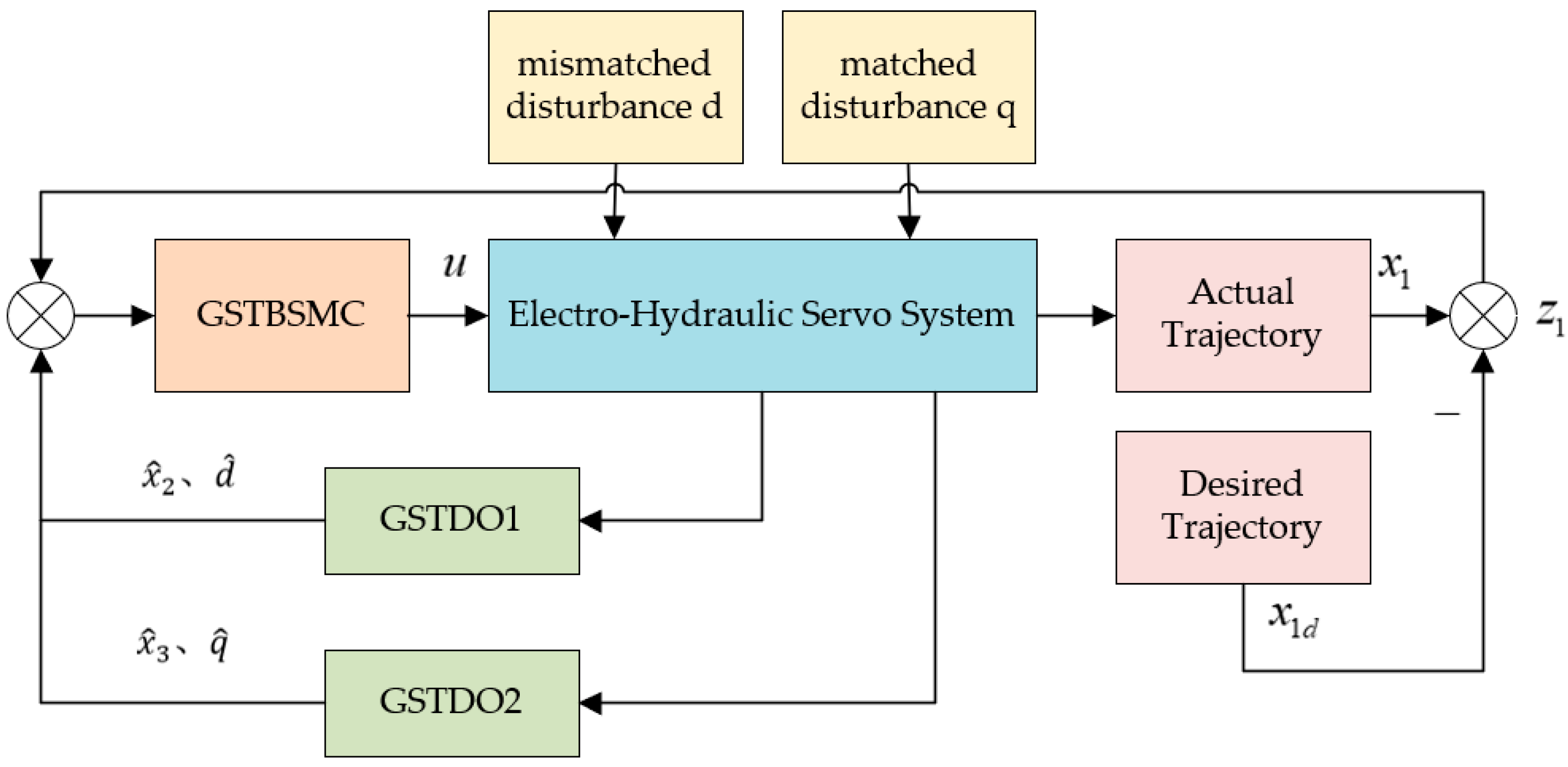
The overall block diagram of the designed controller is shown in Figure 2.

Figure 2.
Overall block diagram of the controller.
3.3. Stability Analysis
Substituting (34) into yields
where is the maximum observation error of the observer. Define
due to
where . Then, if is guaranteed to be a positive definite matrix, we have
The parameters in the selection controller satisfy the following inequalities:
It can be guaranteed that is a positive definite matrix when
can be regained as
As the error of the observer gradually converges to zero, i.e., , when and thus , and , then , and the asymptotic stability of the system is achieved.
4. Simulation Analysis
In order to verify the feasibility of the strategy proposed in this paper, simulation experiments are carried out. The generalized super-twisting backstepping sliding mode controller based on a generalized super-twisting disturbance observer (GSTDO-GSTBSMC) proposed in this paper is compared with the sliding mode controller based on a nonlinear disturbance observer (NDO-SMC). NDO is the most basic and commonly used disturbance observer. SMC is a commonly used method in the control of electro-hydraulic servo systems in recent years, which is robust regarding systems with external disturbances and parameter uncertainties. Therefore, it is a good choice for comparing with NDO-SMC to see whether the proposed control method is effective. The parameters of the simulated hydraulic motor are shown in Table 1, which are from the real experimental platform. The parameters of the controller designed in this paper are shown in Table 2. The parameters of GSTDOs and GSTBSMC are selected according to dynamic and stability constraints.

Table 1.
System Parameters.

Table 2.
Controller Parameters.
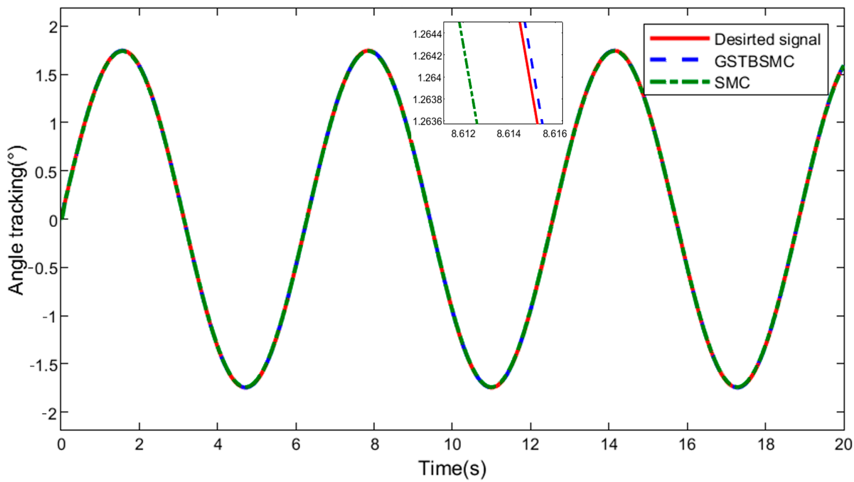
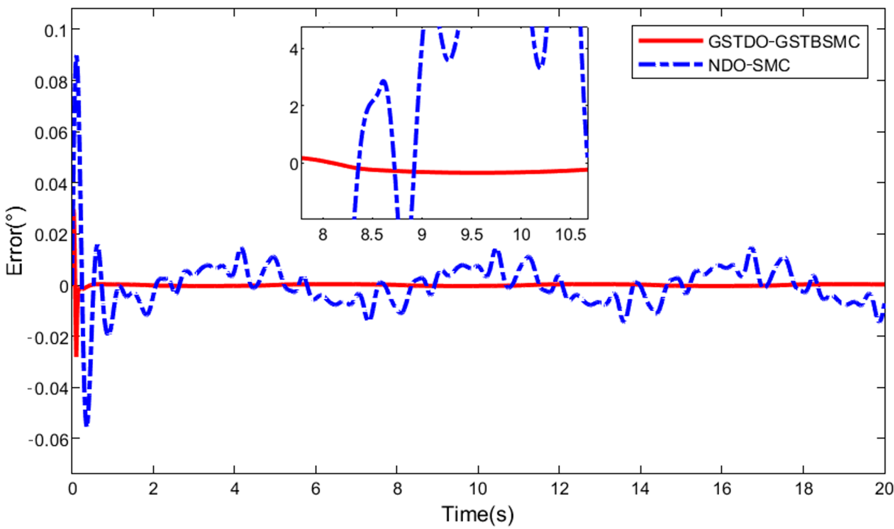
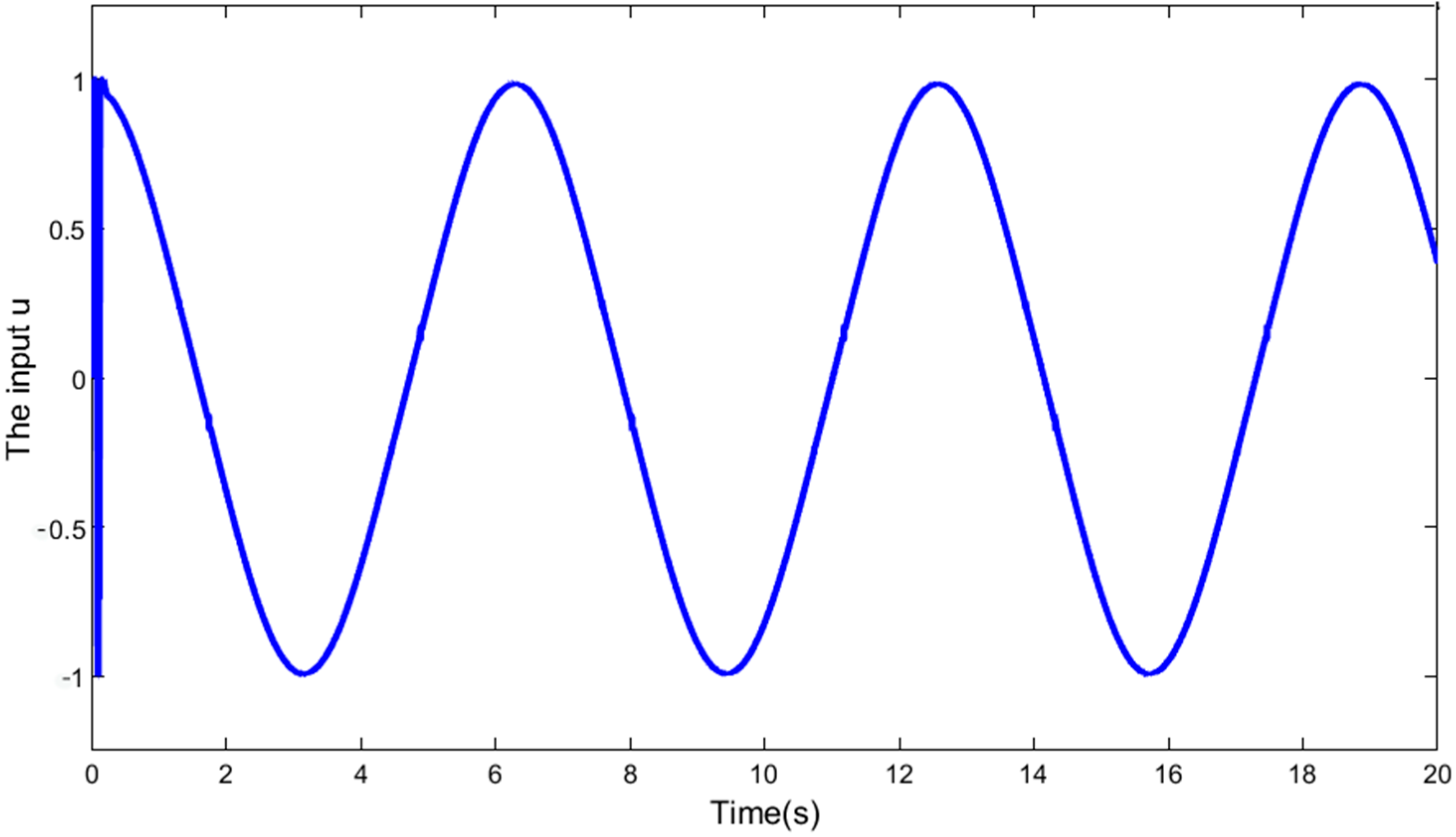
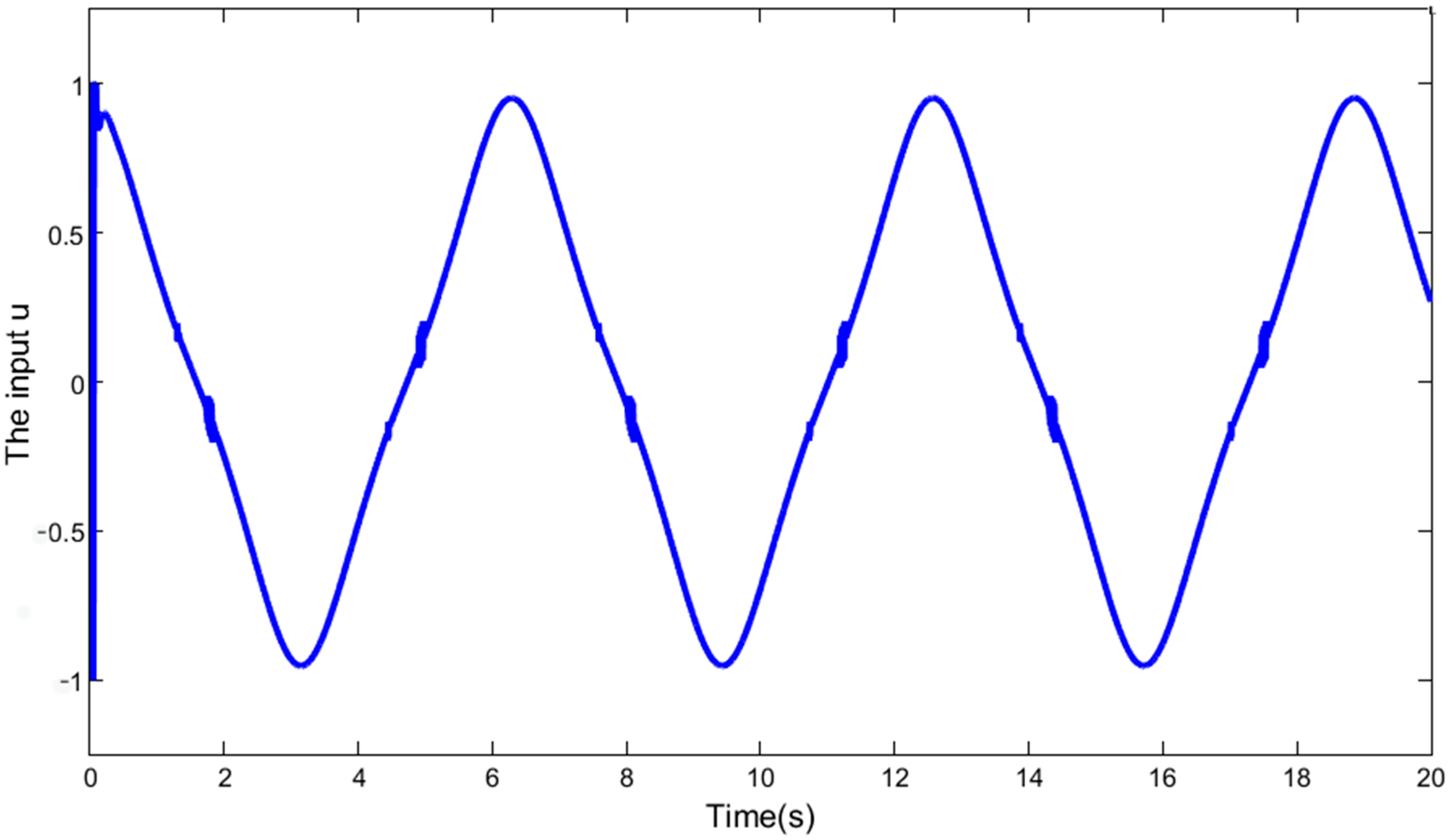
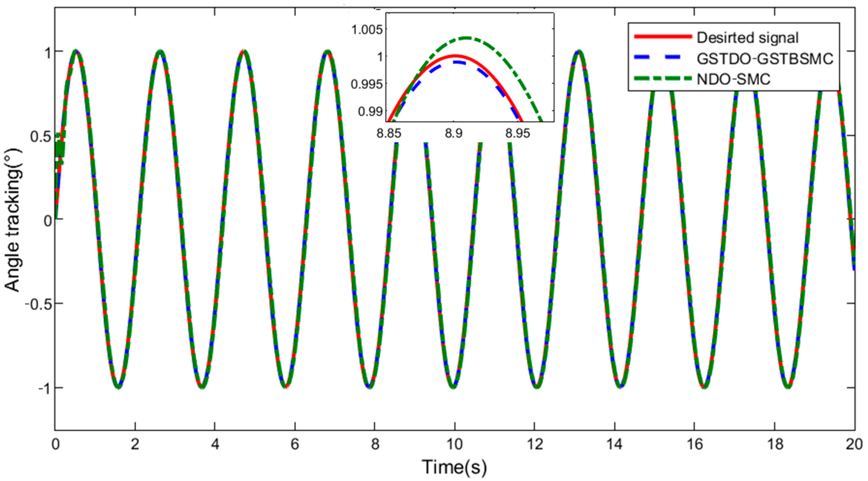
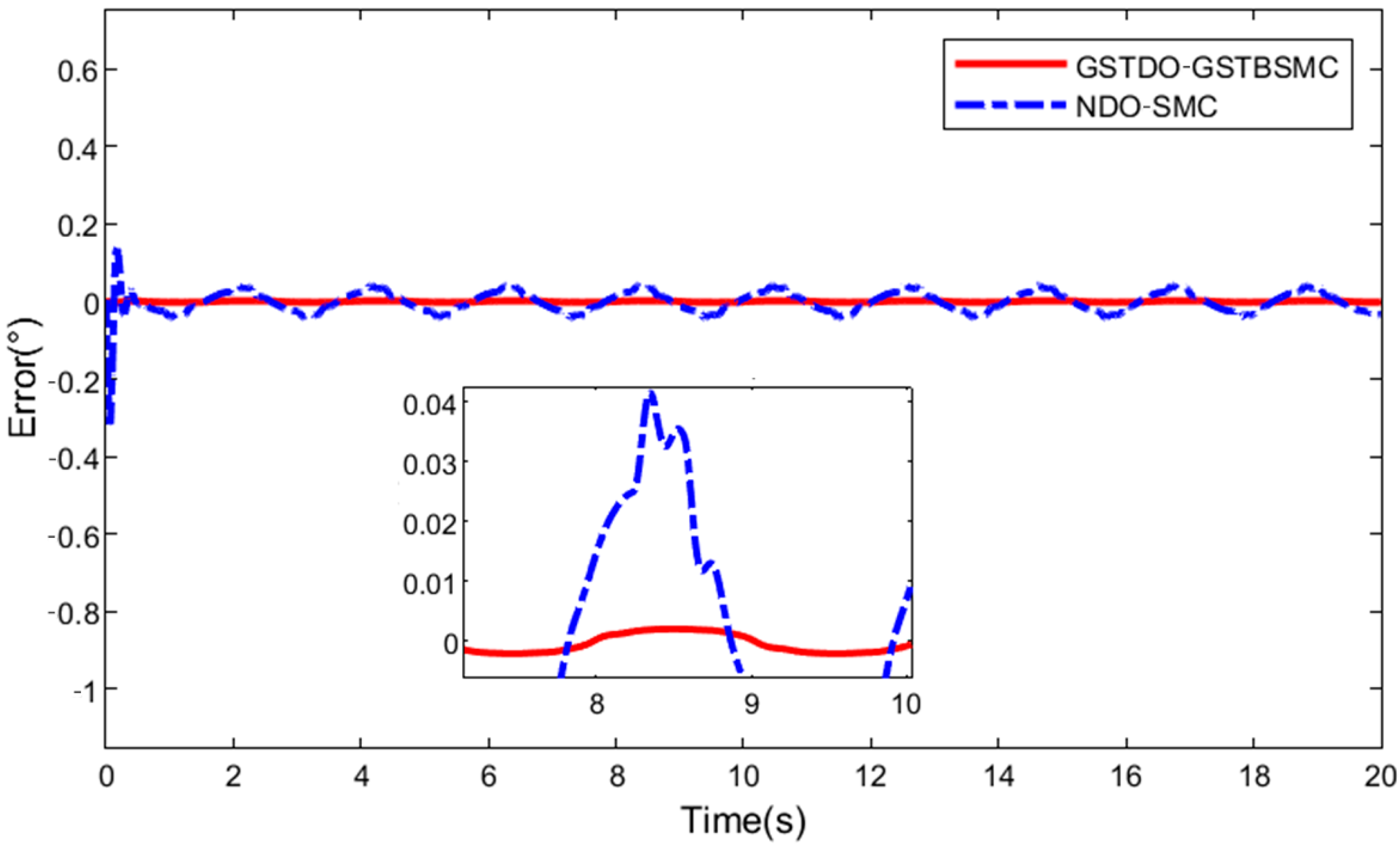
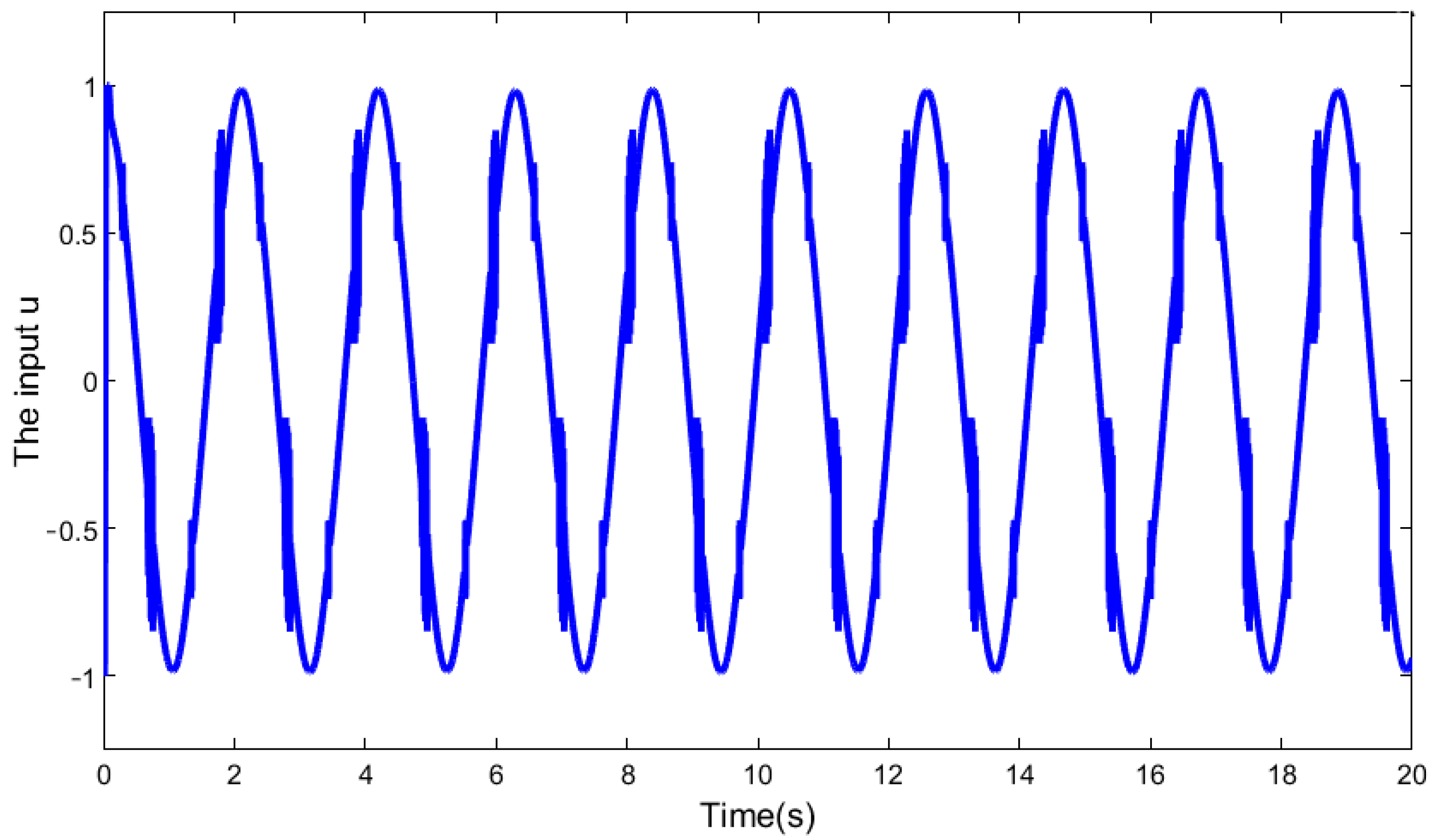
First, the sinusoidal signal is selected as the control target, the mismatched disturbance is + 1 and the matched disturbance is . The tracking results of the above two controllers under the same conditions are shown in Figure 3, and the tracking error curves are shown in Figure 4. It is obvious that GSTDO-GSTBSMC has the better tracking performance. Compared with the initial tracking error of NDO-SMC of +0.09~−0.06°, the initial tracking error of GSTDO-GSTBSMC is +0.03~−0.03°, which can converge to the desired curve in a shorter time of 0.5 s, and the error is almost 0. In the presence of disturbances, the error of NDO-SMC will increase significantly, and the proposed controller can still guarantee good tracking performance. The control input of the GSTDO-GSTBSMC is normalized as shown in Figure 5 below.

Figure 3.
Comparison of the tracking results of GSTDO-GSTBSMC and NDO-SMC in Experiment 1.

Figure 4.
Comparison of the tracking error between GSTDO-GSTBSMC and NDO-SMC in Experiment 1.

Figure 5.
Control input for GSTDO-GSTBSMC u in Experiment 1.
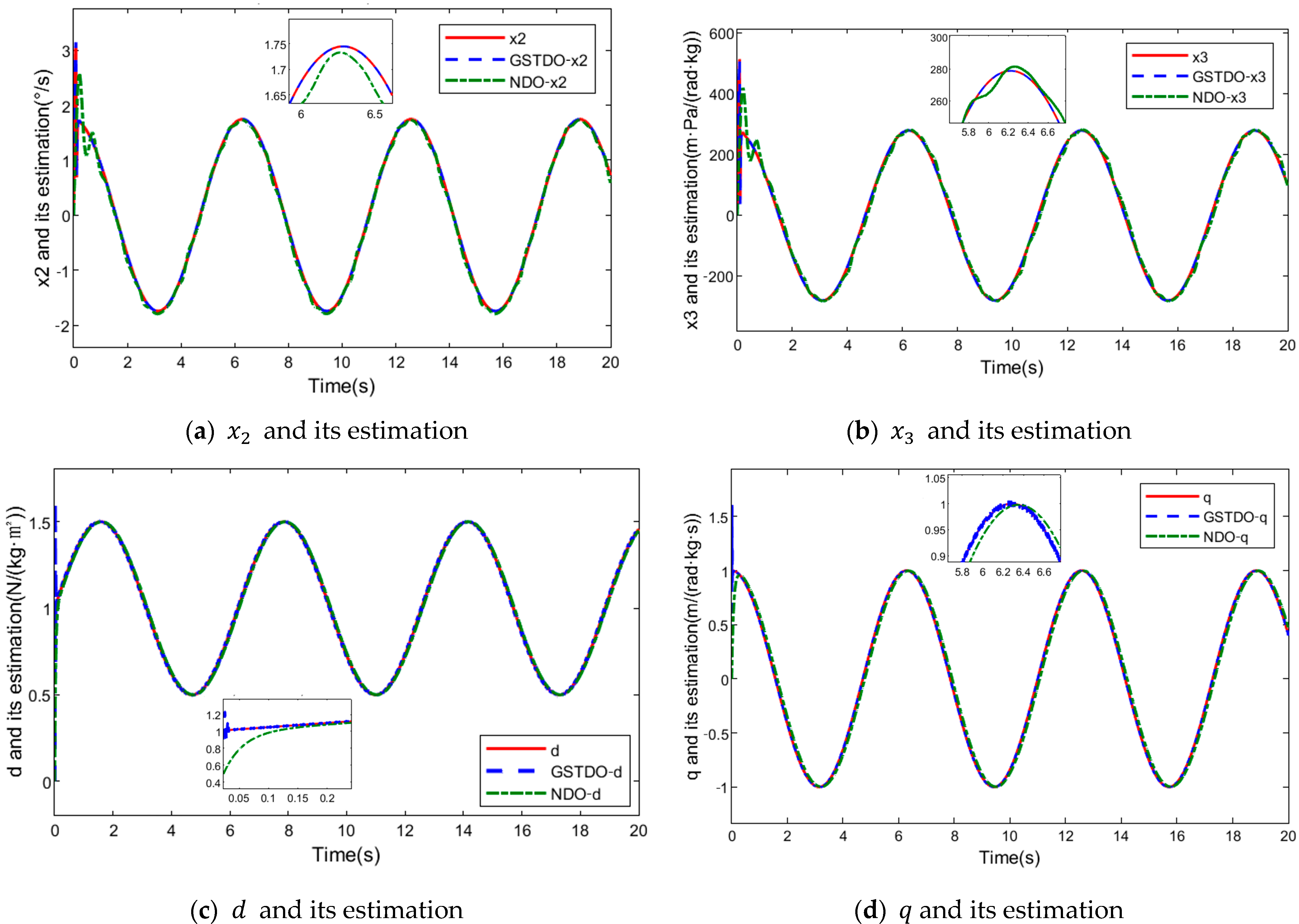
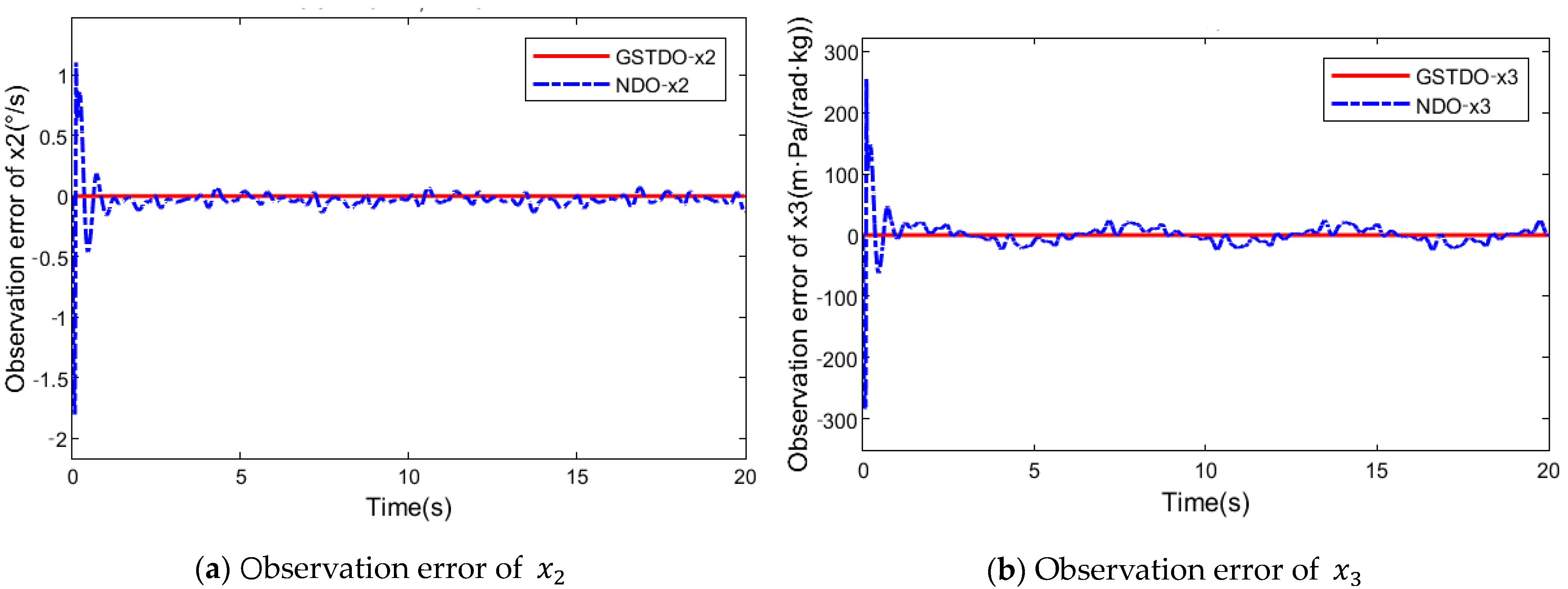
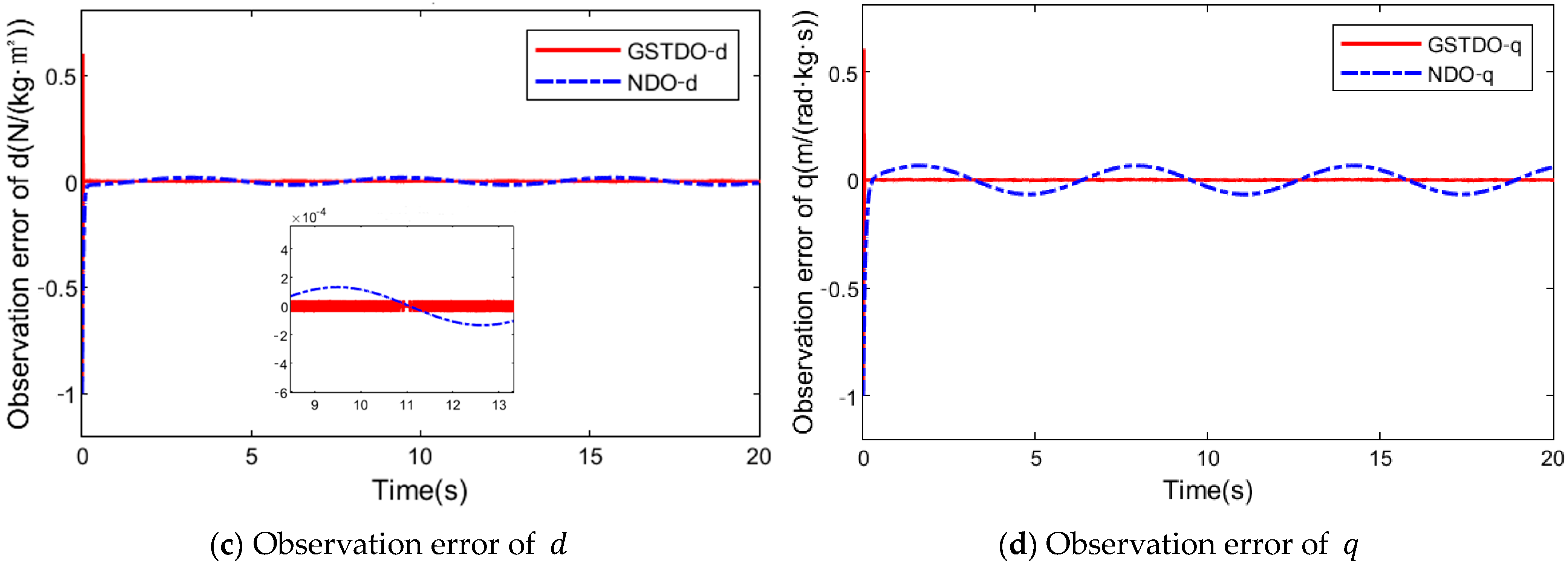
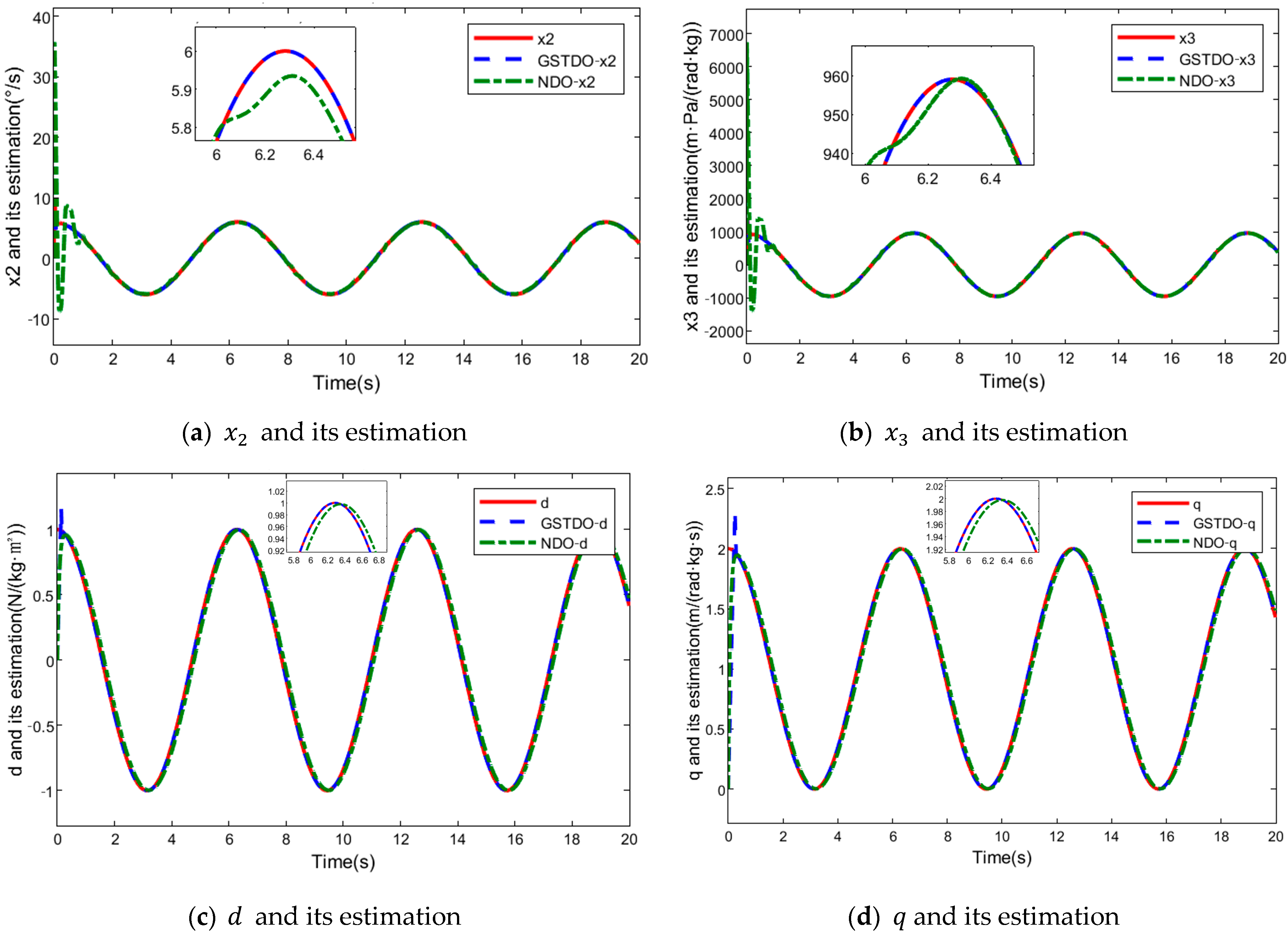
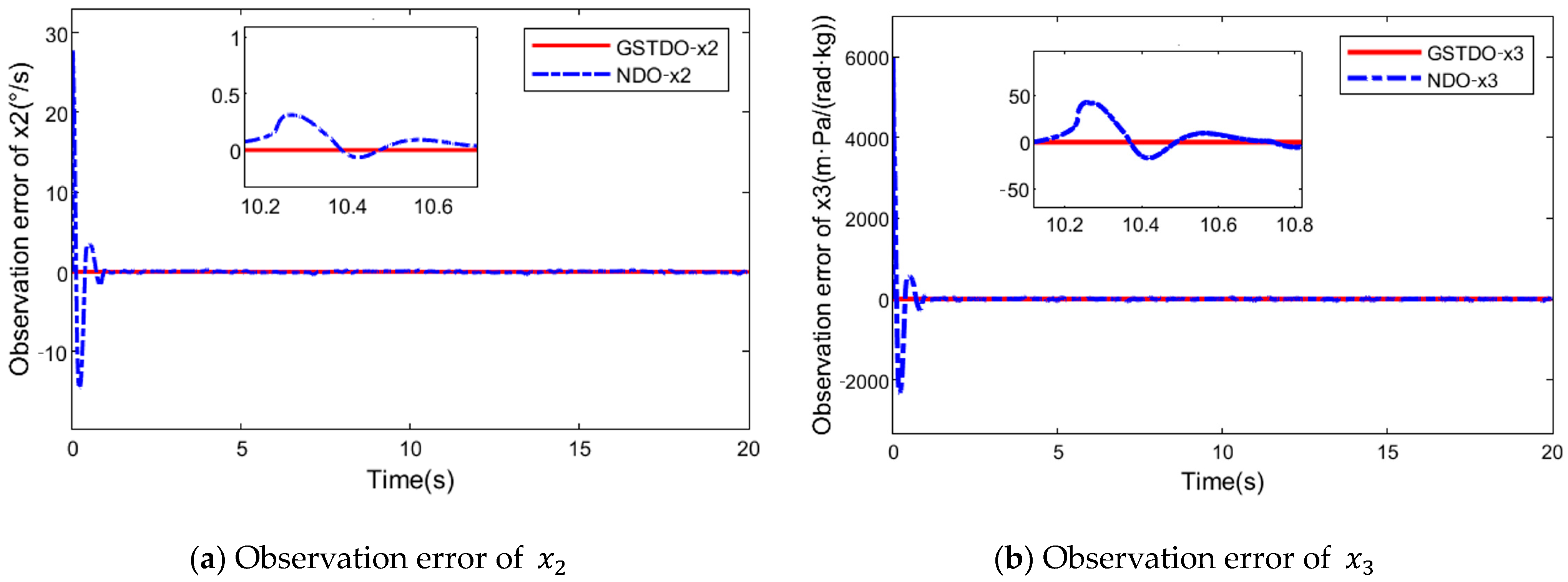
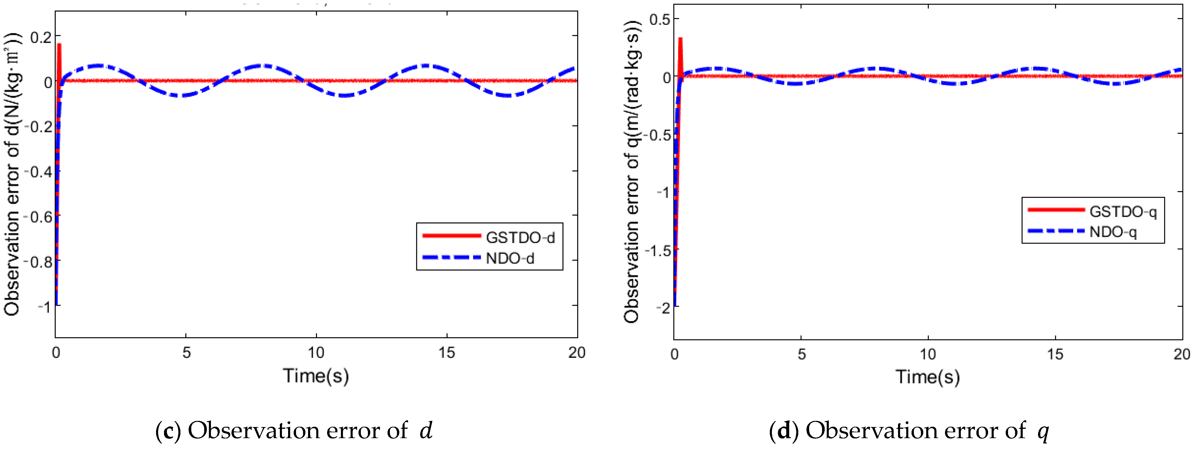
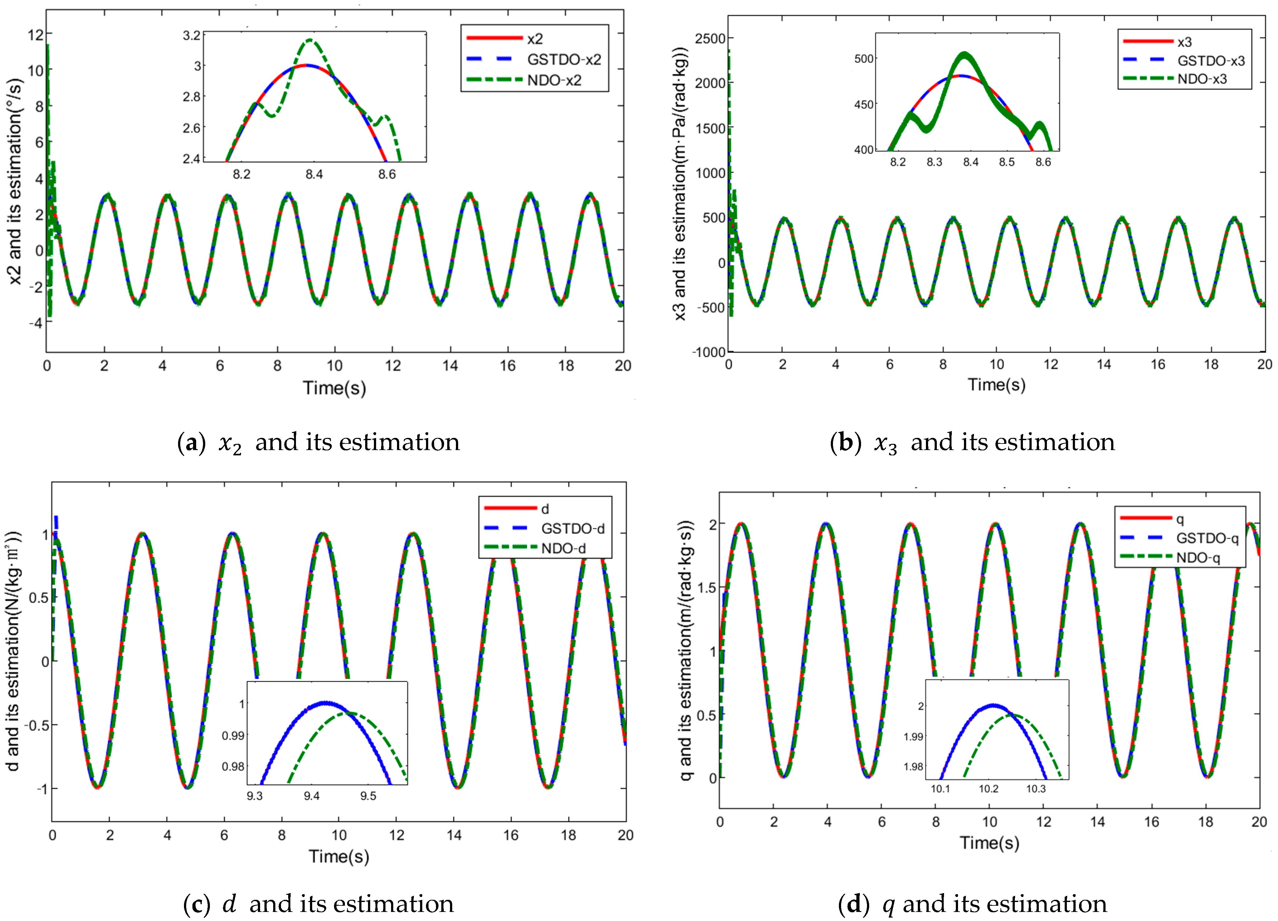
The observation performance of the observers in the above two control methods is shown in Figure 6 and Figure 7. In the experiments, , as well as the mismatched disturbance and the matched disturbance are observed, respectively. From the observation results, it can be seen that the proposed GSTDOs in this paper have better observation performance. In the observation of , the initial maximum observation error of NDO reaches +1.15~−1.75 and gradually stabilizes to +0.08~−0.08, while the error of GSTDO is almost 0. In the observation of , the initial maximum observation error of NDO reaches +250~−280 and gradually stabilizes to +15~−15, while the error of GSTDO is almost 0. In the observation of , the initial maximum observation error of NDO reaches −1. It gradually stabilizes to +0.02~−0.02 after 1.5 s, and the initial maximum observation error of GSTDO is +0.6~−1, but it converges to the actual value. In the observation of , the initial maximum observation error of NDO reaches −1 and gradually stabilizes to +0.07~−0.07 after 0.5 s, and the initial maximum observation error of GSTDO is +0.6~−1 but converges to the actual value in 0.03 s. In summary, NDO has an obvious observation error at the beginning, it takes some time to approach the true value and there will always be an observation error. The GSTDOs proposed in this paper can observe the real value from the beginning and keep the observation error at almost zero, and the convergence time is lower. This provides great convenience for solving modeling uncertainties that cannot be directly obtained in practice and values that cannot be directly measured.

Figure 6.
Comparison of the observational effects of GSTDO and NDO in Experiment 1.


Figure 7.
Comparison of the observation error of GSTDO and NDO in Experiment 1.
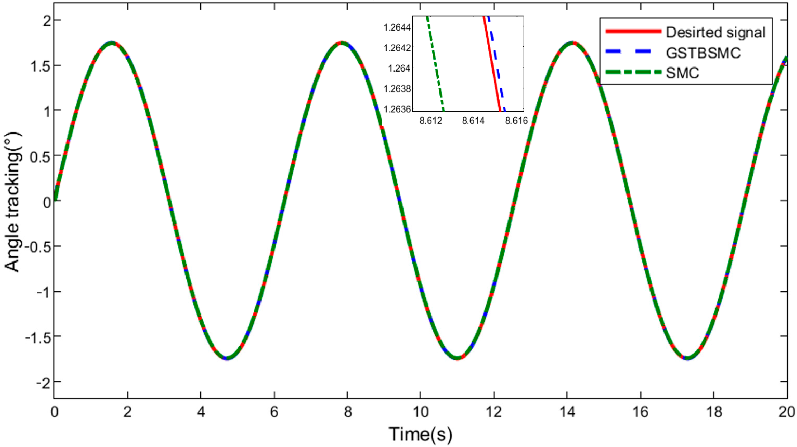
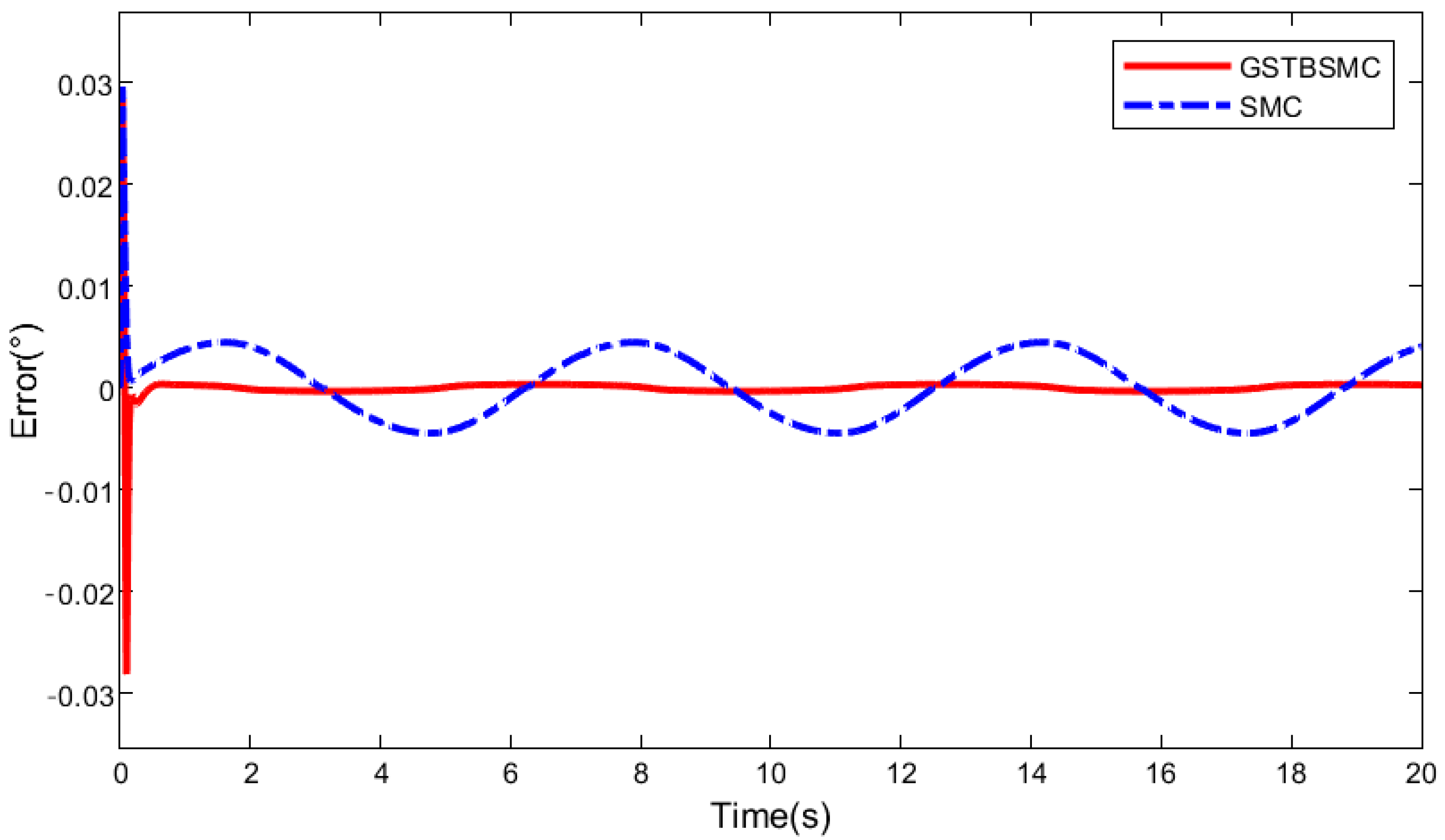
In order to further verify the effectiveness of the controller and eliminate the influence of the observer on it. In the experiment, both controllers are compared based on the observer proposed in this paper. The results of GSTBSMC and SMC are shown in Figure 8 and Figure 9. The initial maximum tracking error of SMC is +0.03°, which gradually stabilizes to +0.005~−0.005°, and the initial maximum tracking error of GSTBSMC is ±0.03°, which in a shorter time of 0.5 s converges to the desired curve, and the error stabilizes at +0.0003~−0.0003°. Obviously, GSTBSMC still has better tracking performance and can asymptotically expect the curve in a shorter time. Its error value is very small, with no significant fluctuations.

Figure 8.
Comparison of the tracking effect of GSTBSMC and SMC in Experiment 1.

Figure 9.
Tracking error comparison between GSTBSMC and SMC in Experiment 1.
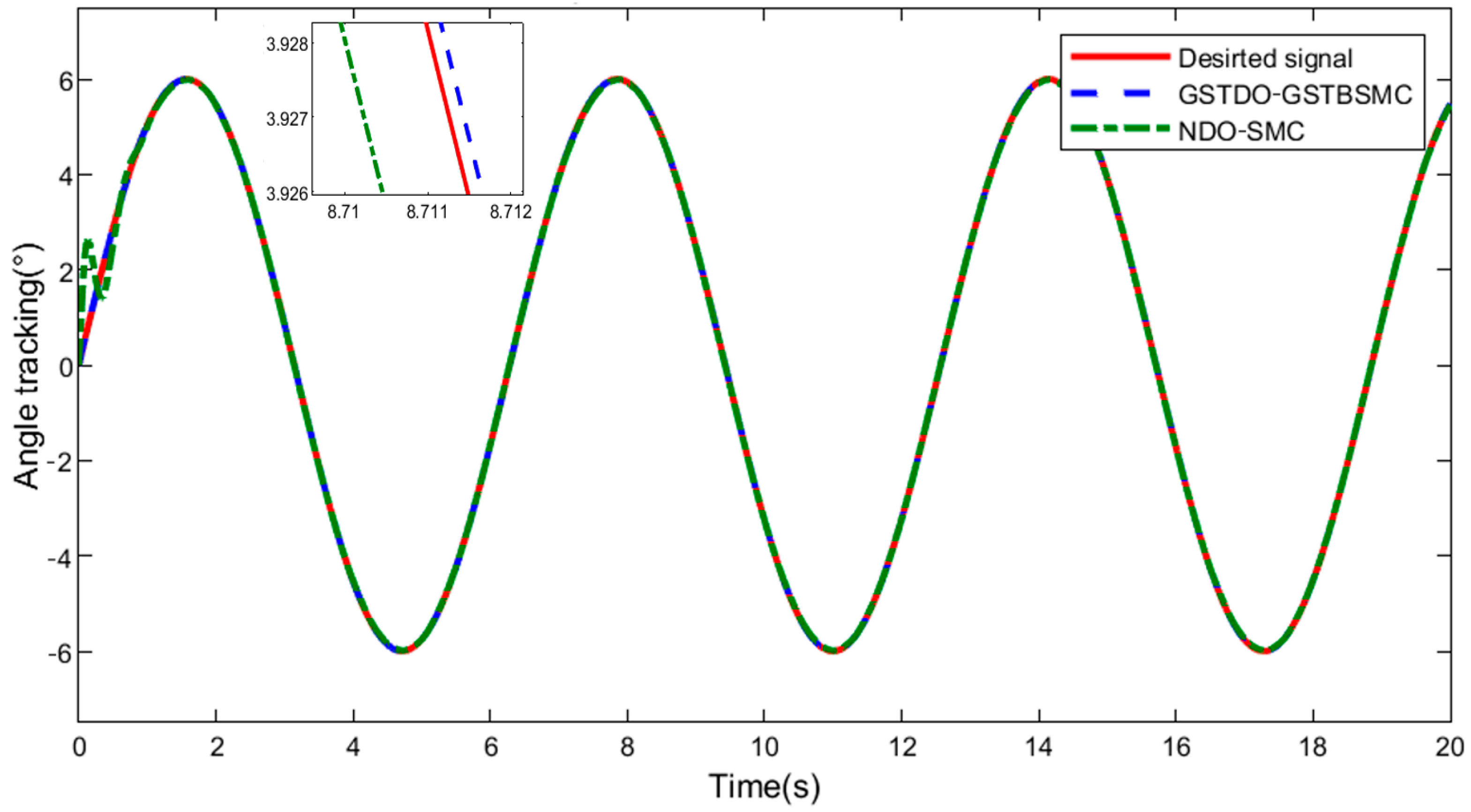
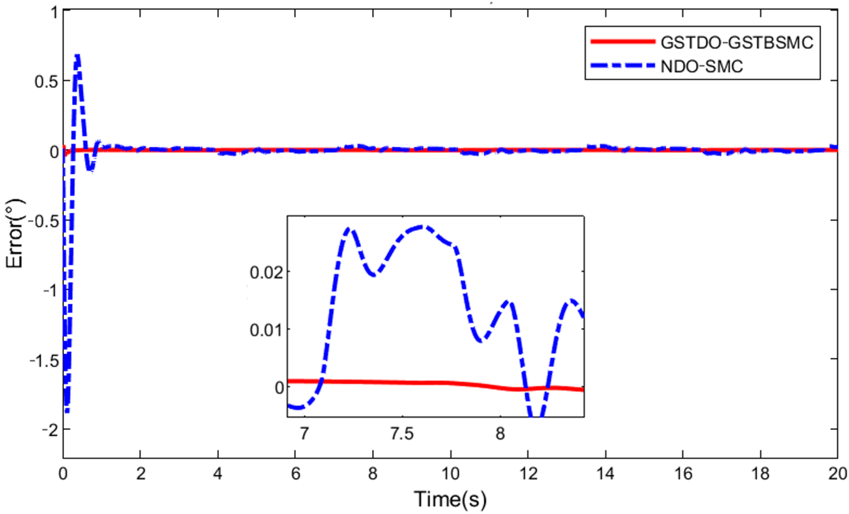
Then, in order to verify the universal applicability of the control algorithm, the amplitude of the control target signal and disturbances is changed, and the two control methods are compared. The sinusoidal signal is selected as the control target, the mismatched disturbance is and the matched disturbance is + 1. The tracking performance of the two controllers under the same conditions is shown in Figure 10, and the tracking error curve is shown in Figure 11. It is obvious that GSTDO-GSTSMC has better tracking performance. Compared with NDO-SMC, the maximum initial tracking error is +0.7~−1.9°, and the maximum initial tracking error of GSTDO-GSTSMC is −0.05°, which can approach the desired curve in a short time of 0.5 s. In the presence of disturbances, the error of NDO-SMC will increase significantly, and the proposed controller can still guarantee good tracking performance. The control input of GSTDO-GSTSMC is normalized as shown in Figure 12 below.

Figure 10.
Comparison of the tracking results of GSTDO-GSTBSMC and NDO-SMC in Experiment 2.

Figure 11.
Comparison of the tracking error between GSTDO-GSTBSMC and NDO-SMC in Experiment 2.

Figure 12.
Control input for GSTDO-GSTBSMC u in Experiment 2.
The observation performance of the observer in the above two control methods is shown in Figure 13 and Figure 14. In the experiment, , , mismatched perturbation and matched perturbation were observed, respectively. It can be seen from the observation results that the GSTDO proposed in this paper has better observation performance. In the observation of , the initial maximum observation error of NDO reaches +27~−15 and gradually stabilizes to +0.4~−0.1, and the GSTDO error is almost 0. In the observation of , the initial maximum observation error of NDO reaches +6000~−2300 and gradually stabilizes to +30~−30, while the error of GSTDO is almost 0. In the observation of , the initial maximum observation error of NDO reaches −1, and the true value is observed after 0.3 s, but there is a delay of 0.1 s. The initial maximum observation error of GSTDO is +0.15~−1, but it converges to the true value at 0.15 s. In the observation of , the initial maximum observation error of NDO reaches −2, and the true value is observed after 0.3 s, but there is a delay of 0.1 s. The initial maximum observation error of GSTDO is +0.3~−2, but it converges to the true value in 0.3 s. In summary, NDO has an obvious observation error at the beginning, it takes some time to approach the true value and there will always be an observation delay. The GSTDO proposed in this paper can always maintain an observation error of almost zero, and the convergence time is lower. In summary, the reliability of the control method proposed in this paper can be proved.

Figure 13.
Comparison of the observational effects of GSTDO and NDO in Experiment 2.


Figure 14.
Comparison of the observation error of GSTDO and NDO in Experiment 2.
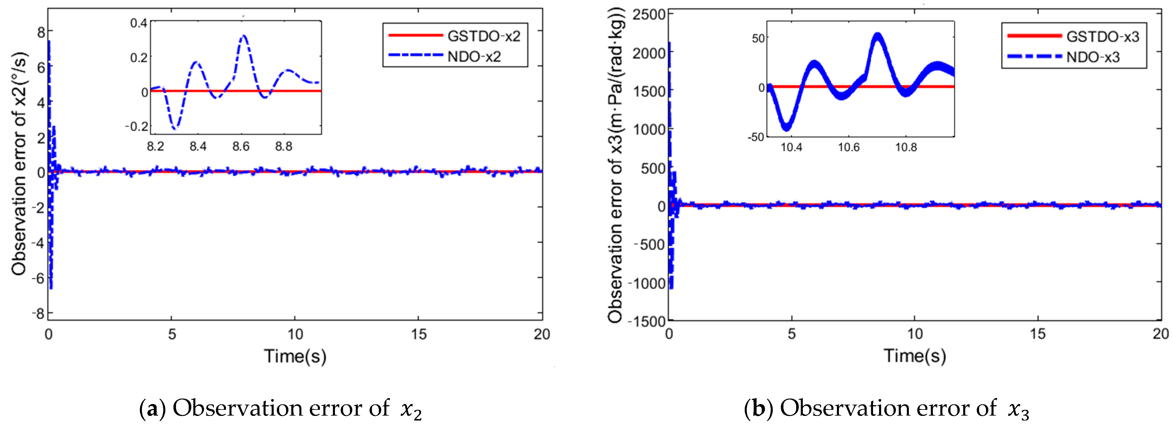
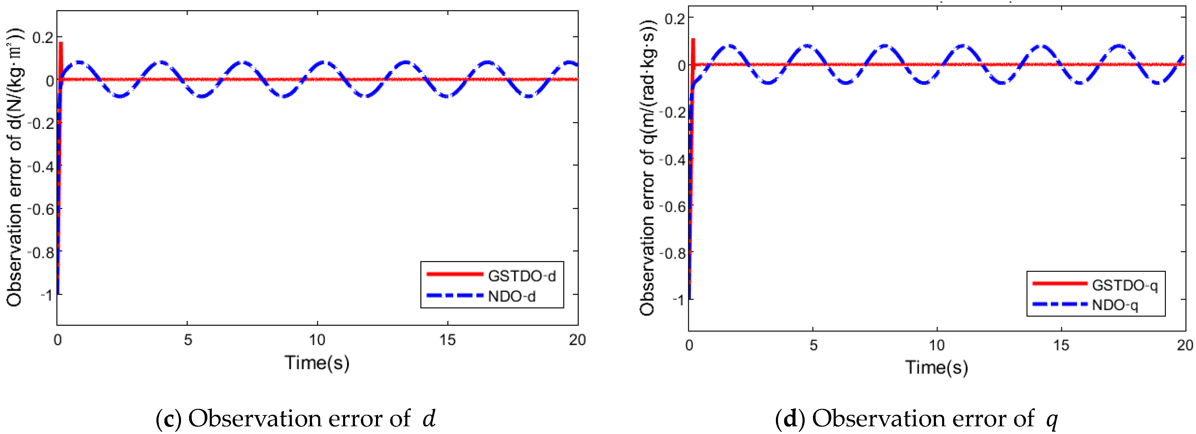
Third, in order to further verify the universal applicability of the control algorithm, the frequency of the control target signal and disturbances is changed. Electro-hydraulic servo systems are real. In the actual engineering background, there will be very large disturbances. Therefore, in this comparative experiment, disturbances are amplified to an order of magnitude with the control target, which can verify the anti-interference ability of the controller. The sinusoidal signal is selected as the control target, the mismatched disturbance is and the matched disturbance is + 1. The tracking performance of the two controllers under the same conditions is shown in Figure 15, and the tracking error curve is shown in Figure 16. It is obvious that GSTDO-GSTSMC has better tracking performance. Compared with NDO-SMC, the maximum initial tracking error is +0.15~−0.32°, and the maximum initial tracking error of GSTDO-GSTSMC is +0.01~−0.01°, which can approach the desired curve in a short time of 0.3 s. In the case of large disturbances, the error of NDO-SMC will increase significantly, and the controller proposed in this paper can still guarantee good tracking performance. The control input of GSTDO-GSTSMC is normalized as shown in Figure 17 below.

Figure 15.
Comparison of the tracking results of GSTDO-GSTBSMC and NDO-SMC in Experiment 3.

Figure 16.
Comparison of the tracking error between GSTDO-GSTBSMC and NDO-SMC in Experiment 3.

Figure 17.
Control input for GSTDO-GSTBSMC u in Experiment 3.
The observation performance of the observer in the above two control methods is shown in Figure 18 and Figure 19. In the experiment, , , mismatched perturbation and matched perturbation were observed, respectively. It can be seen from the observation results that the GSTDO proposed in this paper has better observation performance. In the observation of , the initial maximum observation error of NDO reaches +7.5~−6.7 and gradually stabilizes to +0.3~−0.3, and the GSTDO error is almost 0. In the observation of , the initial maximum observation error of NDO reaches +2150~−1100 and gradually stabilizes to +55~−45, while the error of GSTDO is almost 0. In the observation of , the initial maximum observation error of NDO reaches −1, and the true value is observed after 0.2 s, but there is a delay of 0.05 s. The initial maximum observation error of GSTDO is +0.17~−1, but it converges to the true value at 0.16 s. In the observation of , the initial maximum observation error of NDO reaches −1, and the true value is observed after 0.8 s, but there is a delay of 0.05 s. The initial maximum observation error of GSTDO is +0.1~−1, but it converges to the true value in 0.2 s. In summary, NDO has a large observation error at the beginning, it takes a period of time to approach the true value and there will always be an observation delay. The GSTDO proposed in this paper can always maintain an observation error of almost 0, and the convergence time is lower. In summary, the reliability of the control method proposed in this paper can be proved.

Figure 18.
Comparison of the observational effects of GSTDO and NDO in Experiment 3.


Figure 19.
Comparison of the observation error of GSTDO and NDO in Experiment 3.
5. Conclusions
For the position control and disturbance observation challenges of electro-hydraulic servo systems, a disturbance observer backstepping sliding mode control based on the GSTA is suggested in this paper. First, matched uncertainty and mismatched uncertainty are considered in the system modeling and control scheme. GSTDOs are designed to observe the states that cannot be directly acquired. Second, in the proposed strategy, using the advantages of GSTA, the SMC based on backstepping makes the tracking error converge quickly. This effectively improves the robustness of the controller. Finally, the proposed control method is compared with the commonly used NDO-SMC through simulation experiments. The simulation results show that the proposed observers and controller have achieved better results. The observed value is obviously closer to the real value, and the tracking accuracy of the controller is obviously improved. The practicability and effectiveness of the algorithm are confirmed.
Author Contributions
Writing—original draft, Q.C.; Writing—review & editing, X.S. All authors have read and agreed to the published version of the manuscript.
Funding
This research received no external funding.
Institutional Review Board Statement
Not applicable.
Informed Consent Statement
Not applicable.
Data Availability Statement
The data cannot be disclosed temporarily.
Conflicts of Interest
The authors declare no conflict of interest.
References
- Jiao, Z.; Liu, X.; Shang, Y.; Huang, C. An Integrated Self-Energized Brake System for Aircrafts Based on a Switching Valve Control. Aerosp. Sci. Technol. 2017, 60, 20–30. [Google Scholar] [CrossRef]
- Wang, L. Compound Impedance Control of a Hydraulic Driven Parallel 3UPS/S Manipulator. Chin. J. Mech. Eng. 2020, 33, 56. [Google Scholar] [CrossRef]
- Schenke, C.; Weber, J. Energy Efficiency of Displacement Control Drive Systems in Hydraulic Forming Presses. J. Manuf. Sci. Eng. 2019, 141, 041013. [Google Scholar] [CrossRef]
- Wos, P.; Dindorf, R. Adaptive Control of the Electro-Hydraulic Servo-System with External Disturbances: Adaptive Control of the Electro-Hydraulic Servo-System with External Disturbances. Asian J. Control 2013, 15, 1065–1080. [Google Scholar] [CrossRef]
- Effect of Leakage in Electrohydraulic Servo Systems Based on Complex Nonlinear Mathematical Model and Experimental Results. Acta Polytech. Hung. 2015, 12, 129–146. [CrossRef]
- Richard, E.; Outbib, R. Feedback Stabilization of an Electrohydraulic System. In Proceedings of the 3rd European Control Conference, Rome, Italy, 5–8 September 1995; pp. 330–334. [Google Scholar]
- Outbib, R.; Rafaralahy, H.; Tafraouti, M. Stabilisation d’un actionneur électrohydraulique en considérant les dynamiques des distributeurs. JESA 2005, 39, 1025–1050. [Google Scholar] [CrossRef]
- Sun, W.; Wang, X.; Zhang, C. A Model-Free Control Strategy for Vehicle Lateral Stability With Adaptive Dynamic Programming. IEEE Trans. Ind. Electron. 2020, 67, 10693–10701. [Google Scholar] [CrossRef]
- Çetin, Ş.; Akkaya, A.V. Simulation and Hybrid Fuzzy-PID Control for Positioning of a Hydraulic System. Nonlinear Dyn. 2010, 61, 465–476. [Google Scholar] [CrossRef]
- Wang, N.; Wang, J.; Li, Z.; Tang, X.; Hou, D. Fractional-Order PID Control Strategy on Hydraulic-Loading System of Typical Electromechanical Platform. Sensors 2018, 18, 3024. [Google Scholar] [CrossRef] [PubMed]
- Yao, J. Model-Based Nonlinear Control of Hydraulic Servo Systems: Challenges, Developments and Perspectives. Front. Mech. Eng. 2018, 13, 179–210. [Google Scholar] [CrossRef]
- Ursu, I.; Tecuceanu, G.; Ursu, F.; Sireteanu, T.; Vladimirescu, M. From Robust Control to Antiwindup Compensation of Electrohydraulic Servo Actuators. Aircr. Eng. Aerosp. Technol. 1998, 70, 259–264. [Google Scholar] [CrossRef]
- Tong, S.; Li, Y. Fuzzy Adaptive Robust Backstepping Stabilization for SISO Nonlinear Systems with Unknown Virtual Control Direction. Inf. Sci. 2010, 180, 4619–4640. [Google Scholar] [CrossRef]
- Guo, Q.; Zhang, Y.; Celler, B.G.; Su, S.W. Backstepping Control of Electro-Hydraulic System Based on Extended-State-Observer With Plant Dynamics Largely Unknown. IEEE Trans. Ind. Electron. 2016, 63, 6909–6920. [Google Scholar] [CrossRef]
- Guo, Q. Parametric Adaptive Estimation and Backstepping Control of Electro-Hydraulic Actuator with Decayed Memory Filter. ISA Trans. 2016, 62, 202–214. [Google Scholar] [CrossRef]
- Sun, W.; Liu, Y.; Gao, H. Constrained Sampled-Data ARC for a Class of Cascaded Nonlinear Systems With Applications to Motor-Servo Systems. IEEE Trans. Ind. Inf. 2019, 15, 766–776. [Google Scholar] [CrossRef]
- HongRu, R.E.N.; Hui, M.A.; HongYi, L.I.; RenQuan, L.U. A Disturbance Observer Based Intelligent Control for Nonstrict-Feedback Nonlinear Systems. Sci. China (Technol. Sci.) 2023, 66, 456–467. [Google Scholar]
- Ren, H.; Deng, G.; Hou, B.; Wang, S.; Zhou, G. Finite-Time Command Filtered Backstepping Algorithm-Based Pitch Angle Tracking Control for Wind Turbine Hydraulic Pitch Systems. IEEE Access 2019, 7, 11. [Google Scholar] [CrossRef]
- Chen, Z.; Helian, B.; Zhou, Y.; Geimer, M. An Integrated Trajectory Planning and Motion Control Strategy of a Variable Rotational Speed Pump-Controlled Electro-Hydraulic Actuator. IEEE/ASME Trans. Mechatron. 2022, 28, 588–597. [Google Scholar] [CrossRef]
- Laghrouche, S.; Plestan, F.; Glumineau, A. Higher Order Sliding Mode Control Based on Integral Sliding Mode. Automatica 2007, 43, 531–537. [Google Scholar] [CrossRef]
- Chen, Z.; Yuan, X.; Wu, X.; Yuan, Y.; Lei, X. Global Fast Terminal Sliding Mode Controller for Hydraulic Turbine Regulating System with Actuator Dead Zone. J. Frankl. Inst. 2019, 356, 8366–8387. [Google Scholar] [CrossRef]
- Yamamoto, Y.; Qiu, J.; Munemasa, Y.; Doi, T.; Nanjo, T.; Yamashita, K.; Kikuuwe, R. A Sliding-Mode Set-Point Position Controller for Hydraulic Excavators. IEEE Access 2021, 9, 153735–153749. [Google Scholar] [CrossRef]
- Dang, X.; Zhao, X.; Dang, C.; Jiang, H.; Wu, X.; Zha, L. Incomplete Differentiation-Based Improved Adaptive Backstepping Integral Sliding Mode Control for Position Control of Hydraulic System. ISA Trans. 2021, 109, 199–217. [Google Scholar] [CrossRef] [PubMed]
- Shen, W.; Yao, D.; Shen, C.; Li, H. Finite-Time Fault-Tolerant Control for Swashplate of Integrated Hydraulic Transformer With Uncertain Mismatched Interference. IEEE Trans. Ind. Electron. 2023, 70, 6347–6355. [Google Scholar] [CrossRef]
- Wang, F.; Chen, G.; Liu, H.; Yan, G.; Zhang, T.; Liu, K.; Liu, Y.; Ai, C. Research on Position Control of an Electro–Hydraulic Servo Closed Pump Control System. Processes 2022, 10, 1674. [Google Scholar] [CrossRef]
- Nguyen, M.H.; Dao, H.V.; Ahn, K.K. Active Disturbance Rejection Control for Position Tracking of Electro-Hydraulic Servo Systems under Modeling Uncertainty and External Load. Actuators 2021, 10, 20. [Google Scholar] [CrossRef]
- Lee, W.; Chung, W.K. Disturbance-Observer-Based Compliance Control of Electro-Hydraulic Actuators With Backdrivability. IEEE Robot. Autom. Lett. 2019, 4, 1722–1729. [Google Scholar] [CrossRef]
- Shen, W.; Pan, J. Angle Tracking Control of Integrated Hydraulic Transformer Inner Loop Servo System. ISA Trans. 2023, 134, 312–321. [Google Scholar] [CrossRef]
- Lin, G.; Li, H.; Ahn, C.K.; Yao, D. Event-Based Finite-Time Neural Control for Human-in-the-Loop UAV Attitude Systems. IEEE Trans. Neural Netw. Learn. Syst. 2022, 1–11. [Google Scholar] [CrossRef]
- Palli, G.; Strano, S.; Terzo, M. Sliding-Mode Observers for State and Disturbance Estimation in Electro-Hydraulic Systems. Control Eng. Pract. 2018, 74, 58–70. [Google Scholar] [CrossRef]
- Davila, A.; Moreno, J.A.; Fridman, L. Variable Gains Super-Twisting Algorithm: A Lyapunov Based Design. In Proceedings of the 2010 American Control Conference, Baltimore, MD, USA, 30 June–2 July 2010; pp. 968–973. [Google Scholar]
- Shao, X.; Zhu, L.; Liu, Y. SMDO-Based Backstepping Terminal Sliding Mode Control Method for Hot Press Hydraulic Position Servo System. In Proceedings of the 27th Chinese Control and Decision Conference (2015 CCDC), Qingdao, China, 23–25 May 2015; Volume 6. [Google Scholar]
- Hoang, Q.; Lee, S.; Dugarjav, B. Super-Twisting Observer-Based Integral Sliding Mode Control for Tracking the Rapid Acceleration of a Piston in a Hybrid Electro-Hydraulic and Pneumatic System. Asian J. Control 2019, 21, 483–498. [Google Scholar] [CrossRef]
- Mohanty, A.; Yao, B. Indirect Adaptive Robust Control of Hydraulic Manipulators With Accurate Parameter Estimates. IEEE Trans. Contr. Syst. Technol. 2011, 19, 567–575. [Google Scholar] [CrossRef]
- Yao, J.; Deng, W.; Jiao, Z. RISE-Based Adaptive Control of Hydraulic Systems With Asymptotic Tracking. IEEE Trans. Automat. Sci. Eng. 2017, 14, 1524–1531. [Google Scholar] [CrossRef]
- Moreno, J.A. On Discontinuous Observers for Second Order Systems: Properties, Analysis and Design. In Advances in Sliding Mode Control; Lecture Notes in Control and Information Sciences; Bandyopadhyay, B., Janardhanan, S., Spurgeon, S.K., Eds.; Springer: Berlin/Heidelberg, Germany, 2013; Volume 440, pp. 243–265. ISBN 978-3-642-36985-8. [Google Scholar]
Disclaimer/Publisher’s Note: The statements, opinions and data contained in all publications are solely those of the individual author(s) and contributor(s) and not of MDPI and/or the editor(s). MDPI and/or the editor(s) disclaim responsibility for any injury to people or property resulting from any ideas, methods, instructions or products referred to in the content. |
© 2023 by the authors. Licensee MDPI, Basel, Switzerland. This article is an open access article distributed under the terms and conditions of the Creative Commons Attribution (CC BY) license (https://creativecommons.org/licenses/by/4.0/).

