
Assembly Error Modeling and Tolerance Dynamic Allocation of Large-Scale Space Deployable Mechanism toward Service Performance

Abstract
:1. Introduction
1.1. Assembly of LSDM
1.2. Assembly Error Modeling
1.3. Tolerance Allocation
1.4. Summary and Contribution
- (i)
- Previous research on LSDM assembly have focused on simulating the microgravity environment during the ground assembly process, and the assembly error model’s significance for service performance improvement is ignored.
- (ii)
- The assembly error modeling methods in the previous literature lack consideration of the different environmental factors between ground assembly and service in space.
- (iii)
- The tolerance allocation in the previous literature is completed before the assembly task starts, which means each processes’ tolerance remains unchanged during assembly. Its input is the as-designed data, and the considerable value of the as-built data collected from the actual assembly process is ignored.
- (i)
- An assembly error modeling method considering the differences in the environment between ground assembly and service in space is proposed, and the an LSDM assembly error model is constructed. This contribution compensates for the first two research gaps mentioned above. On the one hand, the assembly error model is used to further reduce gravity’s influence on the service performance in space, on the premise of gravity compensation. On the other hand, the assembly error model considers the different environments of the ground assembly and service in space, regarding gravity variation as the main influencing factor and introducing the changes in the hinge clearance and truss rod length caused by gravity variations into the error model.
- (ii)
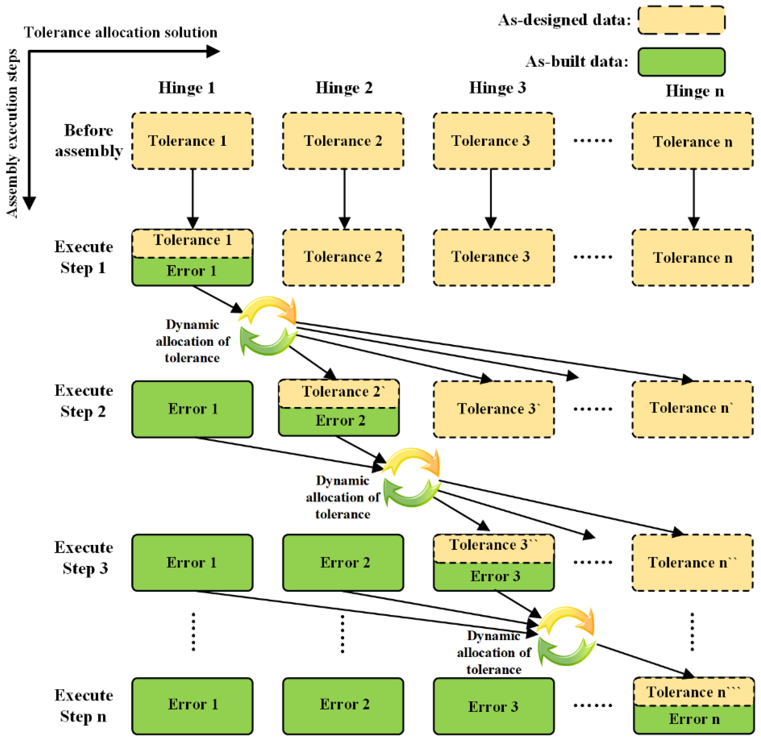
- A tolerance dynamic allocation method based on the as-built data is proposed. This contribution aims to compensate for the last research gap mentioned above. The as-built data measured during the assembly process have considerable value for tolerance allocation. The proposed method can dynamically allocate tolerance for subsequent processes using the completed processes’ as-built data, which can relax the tolerance while guaranteeing the assembly quality. Therefore, it can reduce the assembly difficulty and cost. Of course, if the as-built data exceed the tolerance, the dynamic tolerance allocation model can be used to evaluate whether the current process should be reworked or to tighten the subsequent processes’ tolerances to ensure the final quality.
2. Influence Factors of Service Performance of LSDM
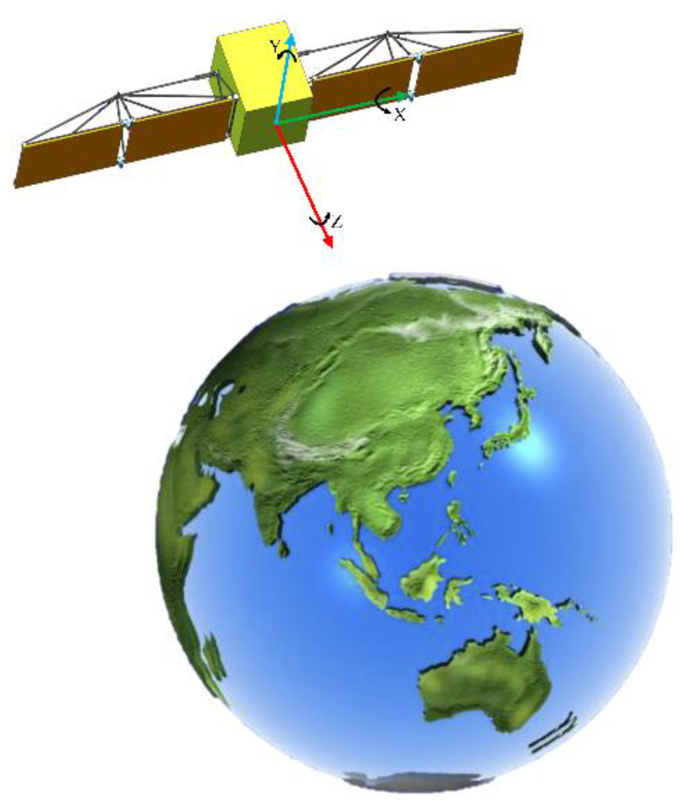
2.1. The Pointing Accuracy of Satellites in Space
2.2. The Influence Factors of Ground Assembly for Service Performance in Space
- (i)
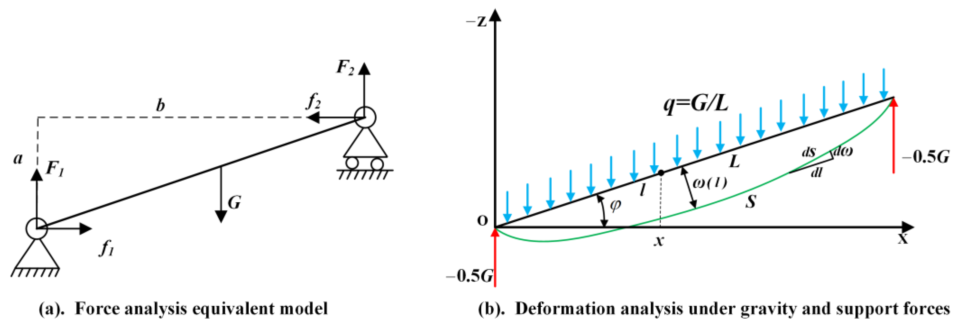
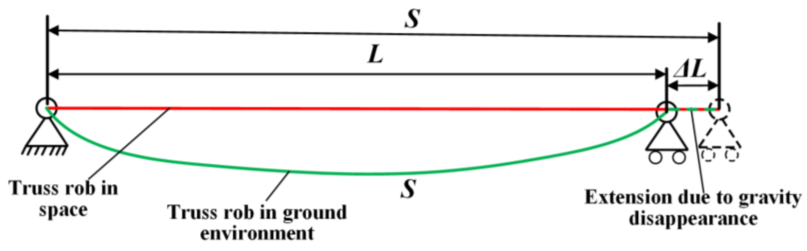
- Deformation of the truss rod. The LSDM’s truss rods consist of carbon fiber and have a large length-to-diameter ratio. During ground assembly, except for the rods installed vertically, the other rods experience bending deformation due to gravity’s influence. When the LSDM is in the space environment where gravity is absent, the bending deformation tends to recover. However, this deformation recovery will affect the pointing accuracy.
- (ii)
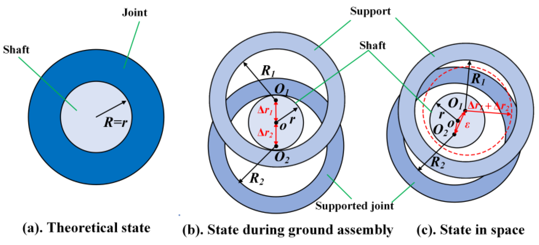
- Clearance of truss hinge. The shaft and hole of the truss hinge usually have clearances. During ground assembly, the hole and shaft are in contact under gravity. However, when the gravity disappears in space, the contact will be changed, which will also affect the pointing accuracy.
2.3. Comparative Analysis of Truss Rod Deformation in Ground and Space Environment
2.4. Comparative Analysis of Hinge Clearance in Ground and Space Environments
3. LSDM Assembly Error Model in Microgravity Assembly on the Ground
3.1. Characteristic Analysis for Truss Rod
- (i)
- Independent Rod. Each end of the rod connects to a hinge, and there is no hinge connected in the middle of the rod. This rod type is the most numerous in the LSDM.
- (ii)
- Coupling Rod. In addition to the hinge at both ends of the rod, there is also one or more hinges at the middle position, and the middle hinge is fixed to the rod. The coupled rod cannot fold around the middle hinge.
- (iii)
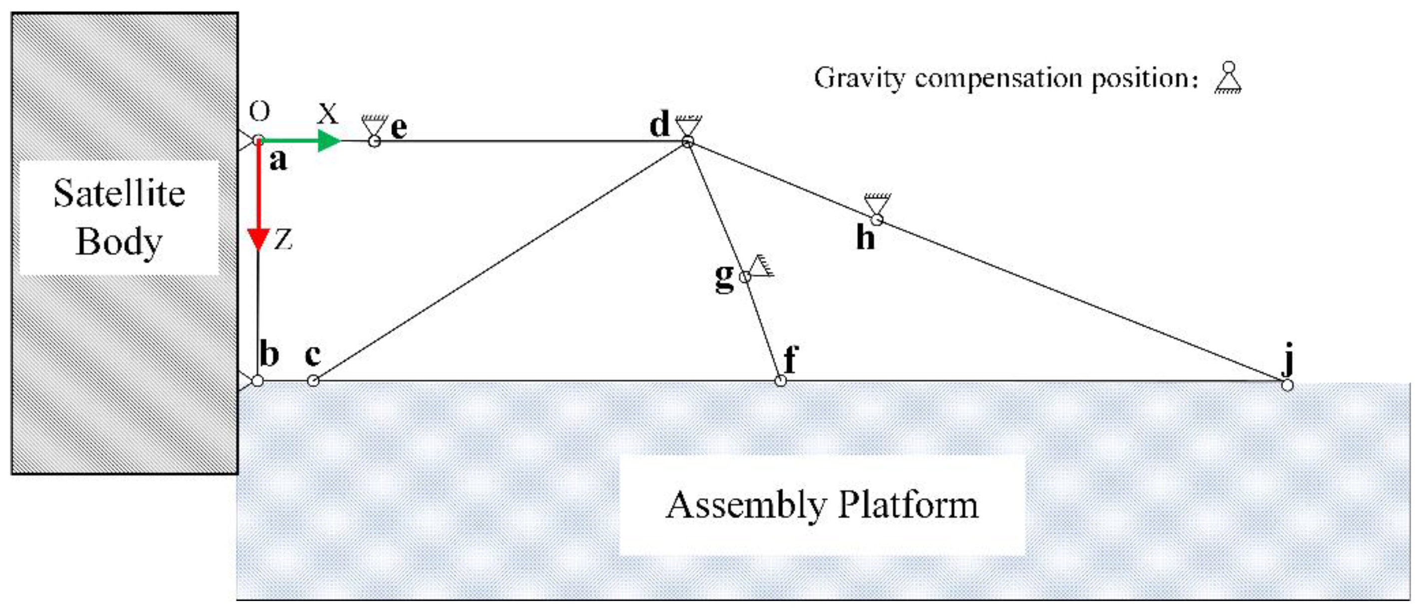
- Equivalent Fixed-Length Rod. The rod is determined by two supports fixed on the antenna panel or satellite body, and the distance between the two supports is not affected by the rod deformation.
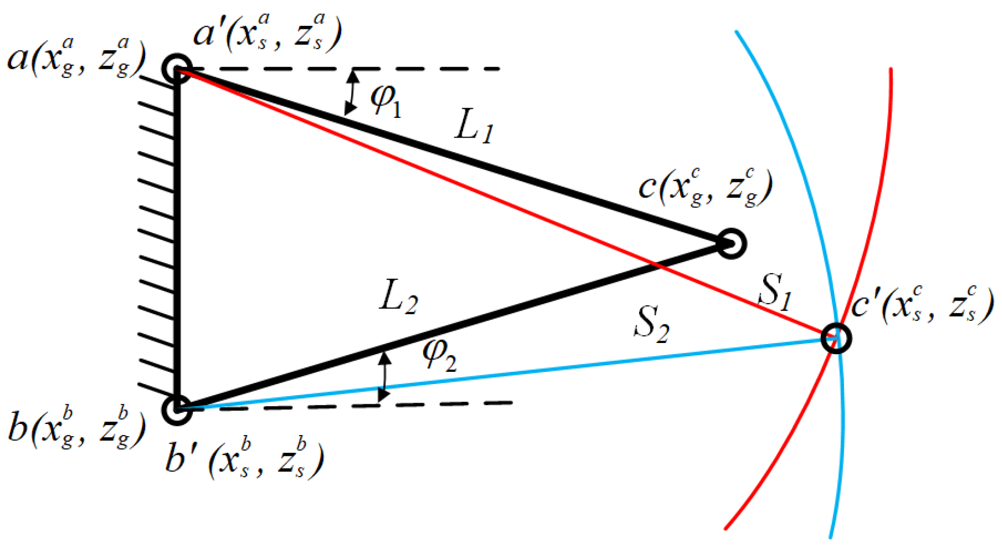
3.2. Assembly Error Propagation of Single-Loop Closed Chain
3.3. Assembly Error Propagation of Multi-Loop Closed Chain
4. Dynamic Tolerance Allocation Based on As-Built Data
4.1. Dynamic Tolerance Allocation Flow among Assembly Processes
4.2. Optimal Tolerance Allocation Based on GA and As-Built Data
5. Case Study
5.1. Experimental Setup
5.2. Experimental Results and Analysis
5.2.1. Pointing Accuracy Analysis
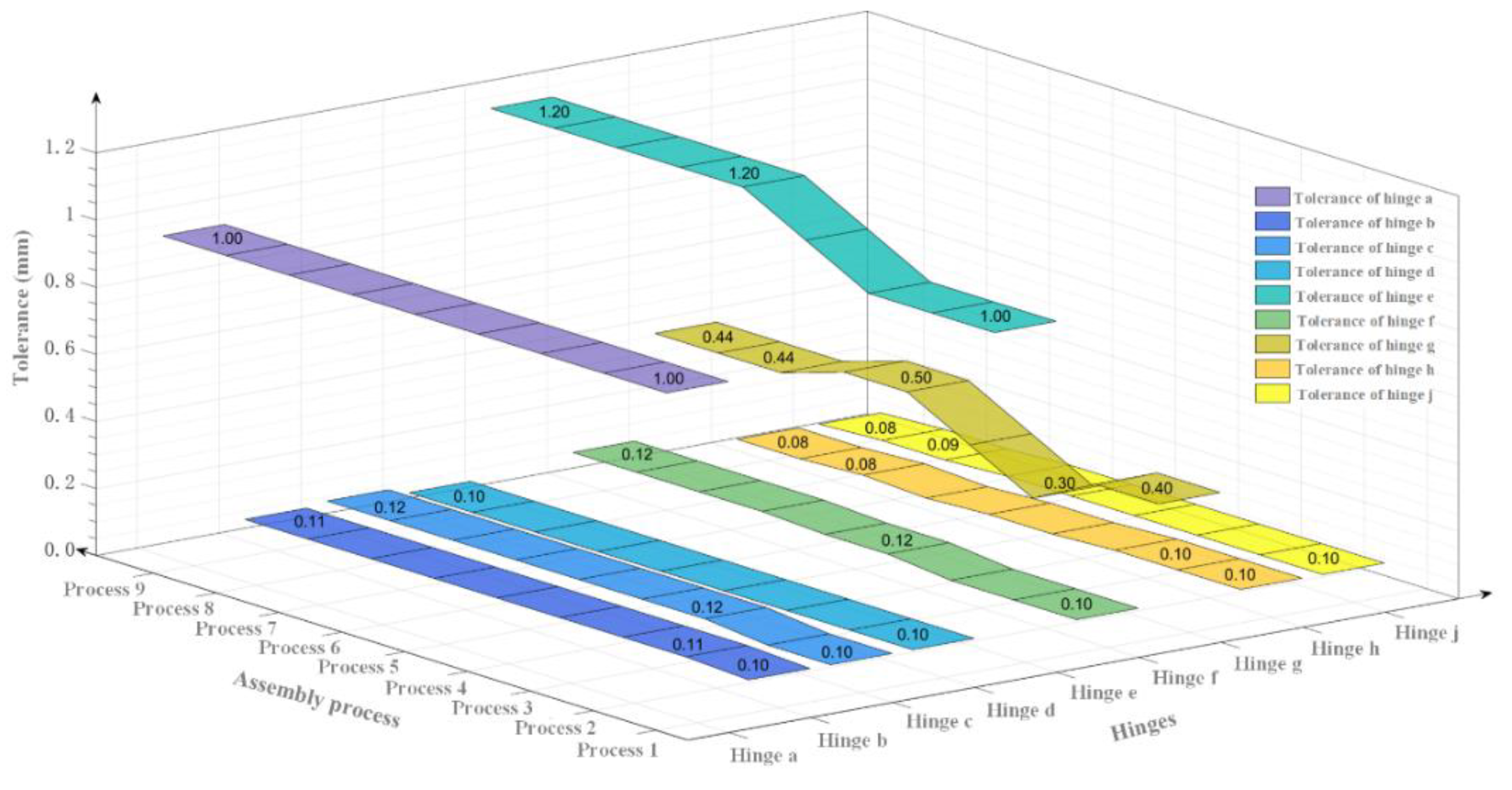
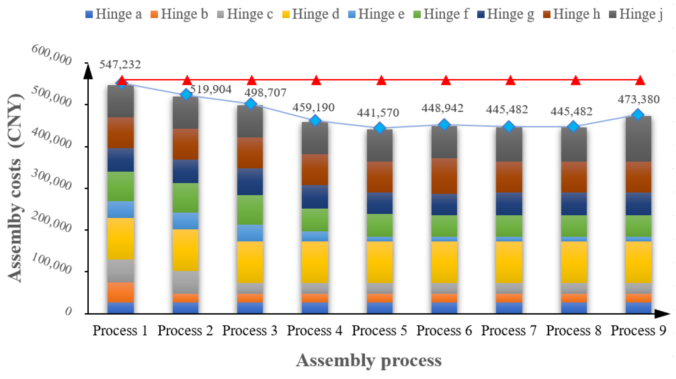
5.2.2. Assembly Cost Analysis
6. Discussion
7. Conclusions and Future Work
Author Contributions
Funding
Institutional Review Board Statement
Informed Consent Statement
Data Availability Statement
Conflicts of Interest
References
- Choi, H.; Kim, D.; Park, J.; Lim, J.H.; Jang, T.S. Modeling and Validation of a Passive Truss-Link Mechanism for Deployable Structures Considering Friction Compensation with Response Surface Methods. Appl. Sci. 2022, 12, 451. [Google Scholar] [CrossRef]
- Chen, X.; Xu, Y.; Lin, Q.; Wang, X.; Li, L.; Cong, Q.; Pan, B. Mechanism design and dynamic analysis of a large-scale spatial deployable structure for space mission. In Proceedings of the SPIE 10322, Seventh International Conference on Electronics and Information Engineering, Nanjing China, 17–18 September 2016; Volume 1032226. [Google Scholar]
- Li, H.Q.; Liu, X.F.; Guo, S.J.; Cai, G.P. Deployment dynamics and control of large-scale flexible solar array system with deployable mast. Adv. Space Res. 2016, 58, 1288–1302. [Google Scholar] [CrossRef]
- Zhang, J.; Wang, H.; Li, Y.; Jiang, L.; Li, D.; He, P. Gravity Compensation Technology of Solar Array Based on Vacuum Negative Pressure Adsorption. J. Mech. Eng. 2020, 56, 202–210. [Google Scholar] [CrossRef]
- Zebenay, M.; Boge, T.; Krenn, R.; Choukroun, D. Analytical and experimental stability investigation of a hardware-in-the-loop satellite docking simulator. Proc. IMechE Part G J. Aerosp. Eng. 2014, 229, 666–681. [Google Scholar] [CrossRef]
- Liu, T.Y.; Wu, Q.P.; Sun, B.Q.; Han, F.T. Microgravity Level Measurement of the Beijing Drop Tower Using a Sensitive Accelerometer. Sci. Rep. 2016, 6, 31632. [Google Scholar] [CrossRef] [PubMed]
- Pletser, V. Short duration microgravity experiments in physical and life sciences during parabolic flights: The first 30 ESA campaigns. Acta Astronaut. 2004, 55, 829–854. [Google Scholar] [CrossRef]
- White, G.C.; Xu, Y. An Active Vertical-Direction Gravity Compensation System. IEEE Trans. Instrum. Meas. 1994, 43, 786–792. [Google Scholar] [CrossRef]
- Jian, X.; Gang, B.; QinJun, Y.; Jun, L. Design and Development of a 5-DOF Air-Bearing Spacecraft Simulator. In Proceedings of the 2009 International Asia Conference on Informatics in Control, Automation and Robotics, Bangkok, Thailand, 1–2 February 2009; pp. 126–130. [Google Scholar]
- Yin, M.; He, Y.; Xu, Z.; Liu, Z.; Shao, X. Design and analysis of physical simulation system for satellite rotating panels. In Proceedings of the The 2016 IEEE International Conference on robotics and biomimetics, Qingdao, China, 3–7 December 2016. [Google Scholar]
- Yang, G.; Wang, H.; Xiao, J.; Wang, Z.; Ling, L. Research on a Hierarchical and Simultaneous Gravity Unloading Method for Antenna Pointing Mechanism. Mech. Sci. 2017, 8, 51–63. [Google Scholar] [CrossRef]
- Fischer, A.; Pellegrino, S. Interaction Between Gravity Compensation Suspension System and Deployable Structure. J. Spacecr. Rockets 2000, 37, 93–99. [Google Scholar] [CrossRef]
- Liu, X.; Zheng, L.; Wang, Y.; Yang, W.; Jiang, Z.; Wang, B.; Tao, F.; Li, Y. Human-centric collaborative assembly system for large-scale space deployable mechanism driven by Digital Twins and wearable AR devices. J. Manuf. Syst. 2022, 65, 720–742. [Google Scholar] [CrossRef]
- Zhang, Z.; Zhang, Z.; Jin, X.; Zhang, Q. A novel modelling method of geometric errors for precision assembly. Int. J. Adv. Manuf. Technol. 2017, 94, 1139–1160. [Google Scholar] [CrossRef]
- He, G.; Shi, P.; Guo, L.; Ding, B. A linear model for the machine tool assembly error prediction considering roller guide error and gravity-induced deformation. Proc. IMechE Part C J. Mech. Eng. Sci. 2020, 234, 2939–2950. [Google Scholar] [CrossRef]
- Guo, F.; Zou, F.; Liu, J.H.; Xiao, Q.; Wang, Z. Assembly error propagation modeling and coordination error chain construction for aircraft. Assem. Autom. 2019, 39, 308–322. [Google Scholar] [CrossRef]
- Guo, F.; Liu, J.; Wang, Z.; Zou, F.; Zhao, X. Positioning error guarantee method with two-stage compensation strategy for aircraft flexible assembly tooling. J. Manuf. Syst. 2020, 55, 285–301. [Google Scholar] [CrossRef]
- Ma, S.; Cai, W.; Wu, L.; Liu, G.; Peng, C. Modelling of transmission accuracy of a planetary roller screw mechanism considering errors and elastic deformations. Mech. Mach. Theory 2019, 134, 151–168. [Google Scholar] [CrossRef]
- Tyagi, S.; Shukla, N.; Kulkarni, S. Optimal design of fixture layout in a multi-station assembly using highly optimized tolerance inspired heuristic. Appl. Math. Modell. 2016, 40, 6134–6147. [Google Scholar] [CrossRef]
- Yang, X.; Ran, Y.; Wang, Z.; Mu, Z.; Zhang, G. Early prediction method for assembly precision of mechanical system and assessment of precision reliability. Int. J. Adv. Manuf. Technol. 2020, 112, 203–220. [Google Scholar] [CrossRef]
- Gregorio, J.; Lartigue, C.; Thiebaut, F.; Lebrun, R. A digital twin-based approach for the management of geometrical deviations during assembly processes. J. Manuf. Syst. 2020, 58, 108–117. [Google Scholar] [CrossRef]
- Mu, X.; Wang, Y.; Yuan, B.; Sun, W.; Liu, C.; Sun, Q. A New assembly precision prediction method of aeroengine high-pressure rotor system considering manufacturing error and deformation of parts. J. Manuf. Syst. 2021, 61, 112–124. [Google Scholar] [CrossRef]
- Liu, J.; Zhang, Z.; Ding, X.; Shao, N. Integrating form errors and local surface deformations into tolerance analysis based on skin model shapes and a boundary element method. Comput.-Aided Des. 2018, 104, 45–59. [Google Scholar] [CrossRef]
- Aghabeigi, M.; Movahhedy, M.R. An algorithm for geometrical uncertainty analysis in planar truss structures. Struct. Multidiscip. Optim. 2013, 49, 225–238. [Google Scholar] [CrossRef]
- Zhao, Q. Deviation Propagation Analysis and Accuracy Modeling for Multi-closed-loop Mechanism. J. Mech. Eng. 2018, 54, 156–165. [Google Scholar] [CrossRef]
- Bai, Z.F.; Sun, Y. A study on dynamics of planar multibody mechanical systems with multiple revolute clearance joints. Eur. J. Mech. A. Solids 2016, 60, 95–111. [Google Scholar] [CrossRef]
- Li, X.; Ding, X.; Chirikjian, G.S. Analysis of angular-error uncertainty in planar multiple-loop structures with joint clearances. Mech. Mach. Theory 2015, 91, 69–85. [Google Scholar] [CrossRef]
- Wang, G.; Yang, Y.; Wang, W.; Chao, L.V. Variable coefficients reciprocal squared model based on multi-constraints of aircraft assembly tolerance allocation. Int. J. Adv. Manuf. Technol. 2015, 82, 227–234. [Google Scholar] [CrossRef]
- Sa, G.; Liu, Z.; Qiu, C.; Tan, J. Tolerance Modeling and Analysis Considering Form Defects for Spaceborne Array Antenna. Appl. Sci. 2020, 10, 2840. [Google Scholar] [CrossRef]
- Zhong, Y.; Qin, Y.; Huang, M.; Lu, W.; Gao, W.; Du, Y. Automatically generating assembly tolerance types with an ontology-based approach. Comput.-Aided Des. 2013, 45, 1253–1275. [Google Scholar] [CrossRef]
- Hallmann, M.; Schleich, B.; Wartzack, S. From tolerance allocation to tolerance-cost optimization: A comprehensive literature review. Int. J. Adv. Manuf. Technol. 2020, 107, 4859–4912. [Google Scholar] [CrossRef]
- Prabhaharan, G.; Asokan, P.; Ramesh, P.; Rajendran, S. Genetic-algorithm-based optimal tolerance allocation using a least-cost model. Int. J. Adv. Manuf. Technol. 2004, 24, 14. [Google Scholar] [CrossRef]
- Zheng, C.; Jin, S.; Lai, X.; Yu, K. Assembly tolerance allocation using a coalitional game method. Eng. Optim. 2011, 43, 763–778. [Google Scholar] [CrossRef]
- Dantan, J.; Eifler, T. Tolerance allocation under behavioural simulation uncertainty of a multiphysical system. CIRP Ann. 2021, 70, 127–130. [Google Scholar] [CrossRef]
- Li, H.; Xu, S.; Keyser, J. Optimization for statistical tolerance allocation. Comput. Aided Geom. Des. 2019, 75. [Google Scholar] [CrossRef]
- Ye, B.; Salustri, F.A. Simultaneous tolerance synthesis for manufacturing and quality. Res. Eng. Des. 2003, 14, 98–106. [Google Scholar] [CrossRef]
- Ghali, M.; Nizar, A. A collaborative hybrid approach for integrated tolerance allocation. Int. J. Computer Integr. Manuf. 2023, 1–19. [Google Scholar] [CrossRef]
- Hsieh, K. The study of cost-tolerance model by incorporating process capability index into product lifecycle cost. Int. J. Adv. Manuf. Technol. 2005, 28, 638–642. [Google Scholar] [CrossRef]
- Li, K.; Gao, Y.; Zheng, H.; Tan, J. A Data-Driven Methodology to Improve Tolerance Allocation Using Product Usage Data. J. Mech. Des. 2021, 143, 071101. [Google Scholar] [CrossRef]
- Balamurugan, C.; Saravanan, A.; Babu, P.D.; Jagan, S.; Ranga Narasimman, S. Concurrent optimal allocation of geometric and process tolerances based on the present worth of quality loss using evolutionary optimisation techniques. Res. Eng. Des. 2016, 28, 185–202. [Google Scholar] [CrossRef]
- Jain, P. Unified approach for tolerance analysis, synthesis, and compensator selection. Appl. Opt. 2022, 61, 8974–8981. [Google Scholar] [CrossRef]
- Natarajan, J.; Sivasankaran, R.; Kanagaraj, G. Bi-objective optimization for tolerance allocation in an interchangeable assembly under diverse manufacturing environment. Int. J. Adv. Manuf. Technol. 2017, 95, 1571–1595. [Google Scholar] [CrossRef]
- Haq, A.N.; Sivakumar, K.; Saravanan, R.; Muthiah, V. Tolerance design optimization of machine elements using genetic algorithm. Int. J. Adv. Manuf. Technol. 2004, 25, 385–391. [Google Scholar] [CrossRef]
- Krishna, A.G.; Rao, K.M. Simultaneous optimal selection of design and manufacturing tolerances with different stack-up conditions using scatter search. Int. J. Adv. Manuf. Technol. 2006, 30, 328–333. [Google Scholar] [CrossRef]
- Cheng, Q.; Zhao, H.; Liu, Z.; Zhang, C.; Gu, P. Robust geometric accuracy allocation of machine tools to minimize manufacturing costs and quality loss. Proc. IMechE Part C J. Mech. Eng. Sci. 2016, 230, 2728–2744. [Google Scholar] [CrossRef]
- Wu, F.; Dantan, J.Y.; Etienne, A.; Siadat, A.; Martin, P. Improved algorithm for tolerance allocation based on Monte Carlo simulation and discrete optimization. Comput. Ind. Eng. 2009, 56, 1402–1413. [Google Scholar] [CrossRef]


| Rod Types | Characteristic | Schematic Diagram |
|---|---|---|
| Independent Rod | The rod connects hinges at both ends, and the length between the two hinges is affected by rod deformation. |  |
| Coupling Rod | In addition to the hinge at both ends of the rod, there is also one or more hinges at the middle position, and the middle hinge is fixed to the rod. |  |
| Equivalent Fixed-Length Rod | The rod is determined by two supports fixed on the antenna panel or satellite body, and the rod is not affected by deformation. | 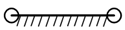 |
| Hinges | X Designed Coordinates | Z Designed Coordinates | X Initial Tolerances | Z Initial Tolerances |
|---|---|---|---|---|
| a | 0.000 | 0.000 | ±0.5 | ±0.5 |
| b | 32.000 | 1225.000 | ±0.5 | ±0.05 |
| c | 167.006 | 1220.008 | ±0.5 | ±0.05 |
| d | 2540.581 | −139.011 | ±0.05 | ±0.5 |
| e | 449.138 | −24.575 | ±0.5 | ±0.5 |
| f | 2692.000 | 1230.000 | ±0.5 | ±0.05 |
| g | 2627.721 | 648.845 | ±0.2 | ±0.2 |
| h | 2999.851 | 68.252 | ±0.05 | ±0.5 |
| j | 5552.000 | 1220.001 | ±0.5 | ±0.05 |
| Truss Rod | Projected Length (mm) | Equivalent Mass (kg) | Angle between Rod and X-axis |
|---|---|---|---|
| ab | 1231.387 | 0.688 | 90.000° |
| bc | 135.099 | 0.075 | 0.000° |
| cd | 2735.103 | 1.528 | −29.794° |
| ed | 2094.571 | 1.170 | −3.132° |
| ae | 449.810 | 0.251 | −3.132° |
| cf | 2525.013 | 1.4106 | 0.000° |
| fg | 584.699 | 0.327 | 83.689° |
| dg | 792.660 | 0.443 | 83.689° |
| fj | 2860.017 | 1.598 | 0.000° |
| hj | 2799.998 | 1.564 | 24.289° |
| dh | 503.872 | 0.281 | 24.289° |
| Close Loop | Hinge | Components | Nominal Diameter (mm) | Fit Type | Clearance Range (mm) |
|---|---|---|---|---|---|
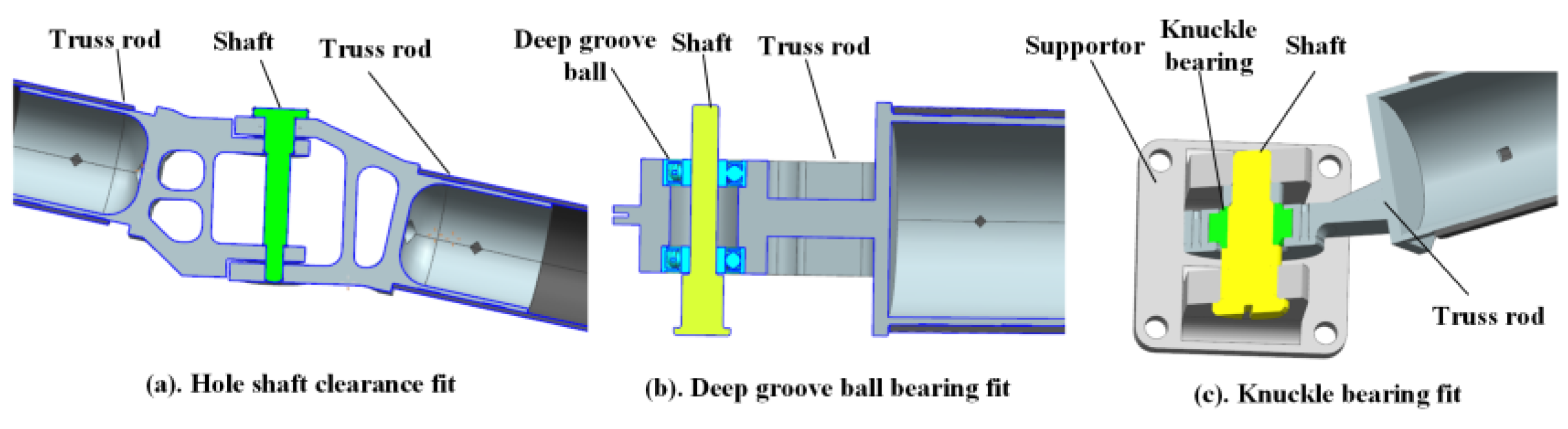
| I | a | ab rod | 6 | Hole–shaft clearance fit | +0.024 +0.004 |
| a shaft | 6 | ||||
| 5 | Deep groove ball bearing fit | +0.013 +0.002 | |||
| ae rod | 5 | ||||
| b | ba rod | 8 | Hole–shaft clearance fit | +0.029 +0.005 | |
| b shaft | 8 | ||||
| 8 | Hole–shaft clearance fit | +0.029 +0.005 | |||
| bc rod | 8 | ||||
| c | cb rod | 10 | Hole–shaft clearance fit | +0.029 +0.005 | |
| c shaft | 10 | ||||
| 12 | Knuckle bearing fit | +0.032 +0.008 | |||
| cd rod | 12 | ||||
| d | dc rod | 12 | Knuckle bearing fit | +0.032 +0.008 | |
| d shaft | 12 | ||||
| 12 | Deep groove ball bearing fit | +0.018 +0.003 | |||
| de rod | 12 | ||||
| e | ea rod | 11 | Hole–shaft clearance fit | +0.035 +0.006 | |
| e shaft | 11 | ||||
| 7 | Deep groove ball bearing fit | +0.013 +0.002 | |||
| ed rod | 7 | ||||
| II | c | cd rod | 12 | Knuckle bearing fit | +0.032 +0.008 |
| c shaft | 12 | ||||
| 10 | Hole–shaft clearance fit | +0.029 +0.005 | |||
| cf rod | 10 | ||||
| e | dc rod | 12 | Knuckle bearing fit | +0.032 +0.008 | |
| d shaft | 12 | ||||
| 12 | Knuckle bearing fit | +0.032 +0.008 | |||
| dg rod | 12 | ||||
| g | gd rod | 10 | Hole–shaft clearance fit | +0.029 +0.005 | |
| g shaft | 10 | ||||
| 10 | Hole–shaft clearance fit | +0.029 +0.005 | |||
| gf rod | 10 | ||||
| f | fg rod | 12 | Knuckle bearing fit | +0.032 +0.008 | |
| f shaft | 12 | ||||
| 12 | Knuckle bearing fit | +0.032 +0.008 | |||
| fc rod | 12 | ||||
| III | d | dg rod | 12 | Knuckle bearing fit | +0.032 +0.008 |
| d shaft | 12 | ||||
| 12 | Knuckle bearing fit | +0.032 +0.008 | |||
| dh rod | 12 | ||||
| g | gd rod | 10 | Hole–shaft clearance fit | +0.029 +0.005 | |
| g shaft | 10 | ||||
| 10 | Hole–shaft clearance fit | +0.029 +0.005 | |||
| gf rod | 10 | ||||
| f | fg rod | 12 | Knuckle bearing fit | +0.032 +0.008 | |
| f shaft | 12 | ||||
| 10 | Hole–shaft clearance fit | +0.029 +0.005 | |||
| fj rod | 10 | ||||
| j | jh rod | 12 | Knuckle bearing fit | +0.032 +0.008 | |
| j rod | 12 | ||||
| 10 | Hole–shaft clearance fit | +0.029 +0.005 | |||
| jf rod | 10 | ||||
| h | hd rod | 10 | Hole–shaft clearance fit | +0.029 +0.005 | |
| h shaft | 10 | ||||
| 10 | Hole–shaft clearance fit | +0.029 +0.005 | |||
| hj rod | 10 |
| Hinge | Assembly Cost Parameters | |||||
|---|---|---|---|---|---|---|
| a0 | a1 | a2 | a3 | a4 | a5 | |
| a | 3.3452 × 10⁵ | −1.4498 × 10⁶ | 3.1431 × 10⁶ | −3.3891 × 10⁶ | 1.7069 × 10⁶ | −3.1847 × 10⁵ |
| b | 8.6004 × 10⁵ | −5.2956 × 10⁷ | 1.3240 × 10⁹ | −1.5006 × 10¹⁰ | 7.6952 × 10¹⁰ | −1.4459 × 10¹¹ |
| c | 3.5005 × 10⁵ | −9.3720 × 10⁶ | 1.1645 × 10⁸ | −5.2197 × 10⁸ | −7.0956 × 10⁸ | 6.9301 × 10⁹ |
| d | 5.7258 × 10⁵ | −2.7379 × 10⁷ | 8.0764 × 10⁸ | −1.2285 × 10¹⁰ | 8.5116 × 10¹⁰ | −2.0389 × 10¹¹ |
| e | 5.3239 × 10⁵ | −2.79438 × 10⁶ | 6.6941 × 10⁶ | −7.5263 × 10⁶ | 3.8618 × 10⁶ | −7.2724 × 10⁵ |
| f | 4.6480 × 10⁵ | −1.9256 × 10⁷ | 4.7950 × 10⁸ | −6.4982 × 10⁹ | 4.2035 × 10¹⁰ | −9.6909 × 10¹⁰ |
| g | 2.1534 × 10⁵ | −1.2744 × 10⁶ | 4.1364 × 10⁶ | −6.5950 × 10⁶ | 4.8727 × 10⁶ | −1.3144 × 10⁶ |
| h | 7.0081 × 10⁵ | −4.8295 × 10⁷ | 1.7002 × 10⁹ | −2.8377 × 10¹⁰ | 2.0653 × 10¹¹ | −5.0759 × 10¹¹ |
| j | 4.2933 × 10⁵ | −2.1676 × 10⁷ | 6.9152 × 10⁸ | −1.1127 × 10¹⁰ | 7.9729 × 10¹⁰ | −1.9453 × 10¹¹ |
Disclaimer/Publisher’s Note: The statements, opinions and data contained in all publications are solely those of the individual author(s) and contributor(s) and not of MDPI and/or the editor(s). MDPI and/or the editor(s) disclaim responsibility for any injury to people or property resulting from any ideas, methods, instructions or products referred to in the content. |
© 2023 by the authors. Licensee MDPI, Basel, Switzerland. This article is an open access article distributed under the terms and conditions of the Creative Commons Attribution (CC BY) license (https://creativecommons.org/licenses/by/4.0/).
Share and Cite
Liu, X.; Zheng, L.; Wang, Y.; Yang, W.; Wang, B.; Liu, B. Assembly Error Modeling and Tolerance Dynamic Allocation of Large-Scale Space Deployable Mechanism toward Service Performance. Appl. Sci. 2023, 13, 4999. https://doi.org/10.3390/app13084999
Liu X, Zheng L, Wang Y, Yang W, Wang B, Liu B. Assembly Error Modeling and Tolerance Dynamic Allocation of Large-Scale Space Deployable Mechanism toward Service Performance. Applied Sciences. 2023; 13(8):4999. https://doi.org/10.3390/app13084999
Chicago/Turabian StyleLiu, Xinyu, Lianyu Zheng, Yiwei Wang, Weiwei Yang, Binbin Wang, and Bo Liu. 2023. "Assembly Error Modeling and Tolerance Dynamic Allocation of Large-Scale Space Deployable Mechanism toward Service Performance" Applied Sciences 13, no. 8: 4999. https://doi.org/10.3390/app13084999
APA StyleLiu, X., Zheng, L., Wang, Y., Yang, W., Wang, B., & Liu, B. (2023). Assembly Error Modeling and Tolerance Dynamic Allocation of Large-Scale Space Deployable Mechanism toward Service Performance. Applied Sciences, 13(8), 4999. https://doi.org/10.3390/app13084999