Article

Analysis and Application of a New S-Type Bistable Generator Beam in Energy Harvester Featured in Reducing Stress Concentration

Reserch Center for Wind Engineering and Engineering Vibration, Guangzhou University, Guangzhou 510006, China
*
Author to whom correspondence should be addressed.
Appl. Sci. 2023, 13(9), 5258; https://doi.org/10.3390/app13095258
Submission received: 25 February 2023 / Revised: 20 April 2023 / Accepted: 21 April 2023 / Published: 23 April 2023

Abstract

:
This paper presents a newly designed bistable S-type generator beam. For two typical energy harvesting scenarios in a low-frequency excitation environment (up-and-down vibration excitation and wind-induced vibration excitation), two kinds of energy harvesting devices are designed using this S-type generator beam and tested and analyzed, respectively. The results indicate that the S-type generator beam can make full use of materials to avoid premature fatigue failure caused by stress concentration. The peak stress of the S-type generator beam is 34.3% lower than that of the cantilever beam under the same excitation conditions. Furthermore, when the environmental excitation frequency is equal to the third natural frequency (3rd mode, 7.45 Hz) of the generator beam, the motion process of the beam surpasses the potential energy barrier and generates inter-well movement (snap-through). The peak output voltage in the two different environments is 14,350 mV and 17,630 mV, respectively. Additionally, the optimal external resistance of the circuit was determined to be 22 kΩ, with a power output of the energy collector of 0.534 mW and 0.545 mW, respectively.

1. Introduction

With the rapid development of electronic devices towards smaller sizes and lower power consumption, energy harvesting has become a realistic method to replace chemical batteries and provide power autonomy for wireless sensor networks [1]. Vibration energy, as a ubiquitous form of ambient energy, has attracted significant attention nowadays [2]. Piezoelectric [3], electromagnetic [4], electrostatic [5], and triboelectric [6] are the most prevalent modes of transduction mechanisms in this field. Among these conversion mechanisms, piezoelectric energy harvesting has been most extensively investigated because of its high efficiency, simple construction, high energy density, and lack of electromagnetic interference with the devices [7].
Much research has validated the aforementioned opinions. For instance, Saman et al. [8] proposed the concept of optimized nonlinear energy harvesting for bridge structures. Kan et al. [9] developed an enhanced piezoelectric wind vibration energy harvester that improved reliability, environmental adaptability, and power generation performance through the interaction between a cylindrical shell and a diamond baffle. Wu et al. [10] proposed an energy harvester that contains an energy barrier, which converts energy from wind-induced vortex excitations into electrical energy using PVDF. Inspired by the flight mechanism of dipteran, Zhou et al. [11] proposed a novel bionic-dipteran energy harvester to collect ultralow-frequency vibration energy. Peng et al. [12] systemic investigated the influence of frequency-up conversion effect on piezoelectric stack generators for high-performance energy harvesting. Wu et al. [13] proposed a novel bistable piezoelectric energy harvester using easy to breakthrough potential well performance to increase output power.
In order to improve the working efficiency of the energy harvester, many research studies have been conducted in this field. In summary, it involves three nonlinear technology methods: amplitude/frequency amplification technology, resonance tuning technology, and multi-stability technology. As for the amplitude amplification technology, the notable research work includes Umeda et al. [14], who introduced a novel energy harvester using a piezoelectric transducer to convert mechanical impact energy into electric energy. Fu et al. [15] proposed a host-parasite vibration harvester that was designed to scavenge random low-frequency vibrations by incorporating bi-stability and frequency up-conversion.
Using resonance tuning technology can enhance the performance of energy harvest by operating harvester at its resonance frequency. For example, Shin et al. [16] presented a breakthrough in demonstrating ultra-wide bandwidth piezoelectric energy harvesters through the automatic resonance tuning phenomenon. Sallam et al. [17] systematically investigated a new proposed energy harvester that employs automatic resonance tuning technology to enhance energy harvesting efficiency. The implementation of these technologies has improved the efficiency of energy harvesters, but most of these designs have complex structures and high production costs, which to some extent limit the application of these technologies [18].
In order to address the aforementioned shortcomings, multi-stable energy acquisition technology has received increasing attention [19,20,21]. Among these technologies, bistable technology has been extensively studied due to its advantages such as simple structure, ease of describing mathematical models, and good energy capture effect [22,23,24]. In multi-stable power systems, the potential function of the system is divided into multiple potential energy wells by potential energy barriers, and the number of potential energy wells is the same as the number of stable states of the system [25,26,27]. Theoretical and experimental research results indicate that the shape of the potential energy well has a significant impact on the performance of the multi-stable collector. When the excitation amplitude is large enough, the system can cross potential energy barriers and jump between different potential energy wells, increasing the response amplitude of the collector’s dynamic structure [28,29]. However, when the input energy of external excitation is relatively low compared to the potential energy barrier, the system is trapped in a single potential energy well for small vibrations [30].
Bistable technology has inspired many interesting designs, such as the mechanically-guided three-dimensional assembly structure proposed by Cao et al. [31], which is strategically designed to construct a soft cruciform-encapsulated piezoelectric energy harvester. Drawing inspiration from wings, Song et al. [32] presented a wings-inspired design that implements a parametric coupling mechanism, thus widening the frequency bandwidth of the energy harvester. Wang et al. [33] proposed the electromagnetic kick method to enhance the output power of a monostable energy harvester through orbit jumps. Hou et al. [34] presented a simple, portable, and bistable energy harvester that can be used to scavenge low-frequency vibrations. Inspired by the rapid shape transition of the Venus flytrap, Qian et al. [35] proposed a novel, low-cost, bistable piezoelectric energy harvester for the purpose of broadband energy harvesting. Therefore, nonlinear technology can really improve the performance of energy conversion [36,37].
In conclusion, it is a feasible scheme to improve energy capture efficiency based on nonlinear technology. In this work, a newly designed bistable S-type generator beam is proposed, and for two typical energy harvesting scenarios in low-frequency excitation environment (the up-and-down vibration excitation and the wind-induced vibration excitation), two kinds of energy harvesting devices designed using this S-type generator beam are tested respectively, and their energy harvesting characteristics and efficiency are analyzed and discussed.

2. Design and Modeling

2.1. Design of “S” Type Power Generation Beam of Energy Harvester

In order to improve the performance of the energy harvester, nonlinear technology is the main way used to enhance the efficiency of energy conversion. The common method is to alter the potential shape of the harvester by providing pre-tightening force or pre-deformation. A generator beam designed as a bistable “S” type energy harvester is proposed here to effectively convert low-frequency, low-amplitude, random vibrations into electricity, as shown in Figure 1a.
The modal properties of the generator beam are analyzed using the finite element method, as shown in Figure 1b. The first mode of the beam is a torsional motion occurring at 2.11 Hz, the second mode is a local small range torsional motion occurring at 3.32 Hz, and the third mode is a bistable motion occurring at 7.45 Hz, which is an ideal state for energy capture as required by the design of the generator beam in the energy harvester. The fourth mode is a torsional motion at 37.63 Hz.
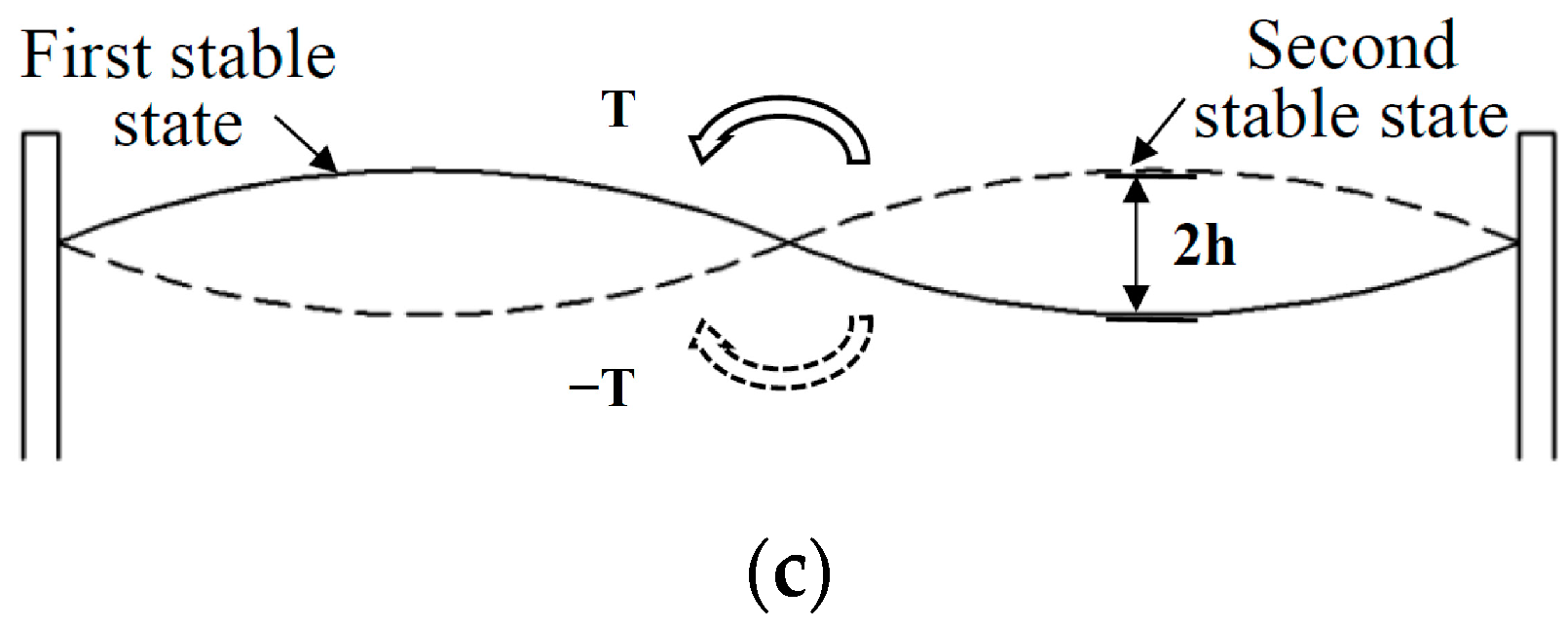
The third mode of generator beam is used in the design of energy harvester as an ideal energy harvesting motion. The generator beam is imposed a pre-deformation of the “S” shape by the clamped columns on both sides, thus having two steady states, when the harvester is excited by the environment, it can perform either small-amplitude motions within a single potential well (intra-well motion) or large-amplitude motions between the two potential wells (inter-well motion), as shown in Figure 1c. The occurrence of inter-well motions requires breaking through potential energy barriers (snap-through), which constitutes a typical bistable structure. Upon suitable environmental stimulus, snap-through occurs and the beam changes from one stable state to the other. A large amplitude of oscillation and a local high-frequency vibration accompanies this process, allowing the harvester to output greater electrical energy.

2.2. Mechanical Model

The S-type generator beam consists of a base steel plate and a PVDF piezoelectric plate attached to the surface of the steel plate. When the middle part of the beam is subjected to torque, the beam will buckle and present bistable state. At the action of external excitation u(t), the piezoelectric beam switches between the two equilibrium states and outputs a large amount of voltage. Considering the influence of gravity, according to Newton’s second law and Kirchhoff’s law [38], the dynamic control equation of the piezoelectric spring mass system can be written as:
M X + C X + 2 K X L l 2 + X 2 l + Θ V + M g = M Z C P V + V R Θ X = 0
where, M is the mass of the piezoelectric vibrator (limit module), X is the amplitude of the generator beam, K is the equivalent stiffness, C is the damping coefficient, l is the length of the generator beam, g is the gravitational acceleration constant, μ(t) is the displacement of the external vibration source as a function of time, V is the output voltage of the piezoelectric sheet, Θ is electromechanical coupling coefficient, and Cp is the equivalent capacitance.
Introduce dimensionless parameter c v , x = L x ¯ ,   u = L a ,   V = c v v , τ = 2 K / M t
x ¯ + 2 ξ x ¯ + ( 1 1 α ) x ¯ + x ¯ 3 2 α 3 + ρ + θ υ = f cos ( ω τ ) υ + λ υ β x ¯ = 0
α = f cos ( w τ ) , f = A L , w = Ω M 2 K , The irrational item was Taylor expand at X = 0, the above equation is rewritten as:
x = y y = 2 ξ y + α 1 x + α 2 x 2 + α 3 x 3 θ v + f cos ( ω τ ) υ = λ υ + β y
The state equation for the motion of the generation beam as a captive energy device is Equation (3). Based on the above mathematical model, the motion state of the beam can be described and predicted.

2.3. FEM Optimization Design

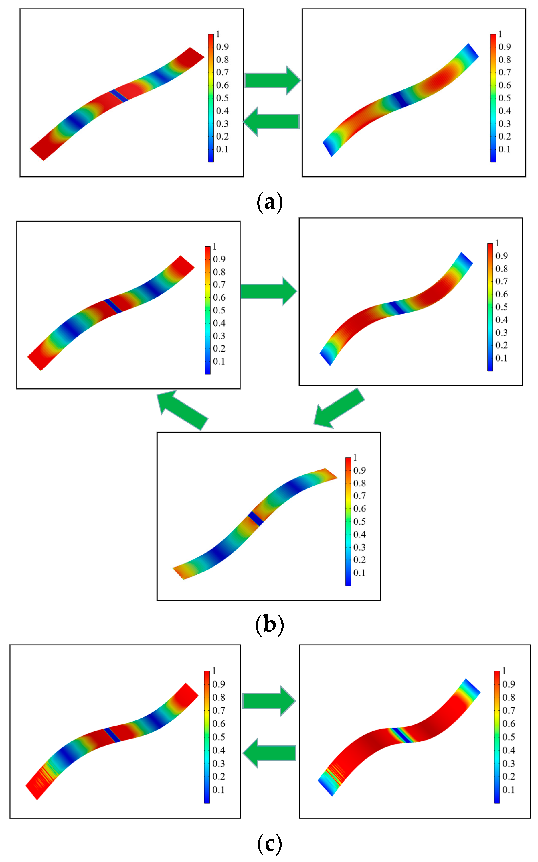
For the bistable generator beam structure, the most critical design parameter is the height of the potential energy well. Optimal sizing is helpful in improving the energy capture efficiency of the energy harvester in low-frequency environments. To analyze and optimize the structure of the S-type generator beam of the energy harvester, we conducted finite element method (FEM) simulations using COMSOL Multiphysics 5.3. Using built-in solvers of the frequency domain, through the analysis of the motion state of the generator beam at the different heights (5 mm, 10 mm and 15 mm) of the potential energy well, the optimal height geometry of the potential energy well is determined.
Using software, fixed constraints were applied at both ends of an S-shaped beam, and a mass block was added at the middle. A low-frequency vertical excitation (0–20 Hz) was then applied to the beam using COMSOL 5.3. The motion states of the power generation beam were analyzed in different potential well heights (5 mm, 10 mm, and 15 mm) to determine the optimal height and geometric shape of the potential well. To clearly demonstrate the motion states of the beam under different geometric sizes, the cloud diagram data has been normalized, and the legend values represent the relative motion states of the power generation beam at different extreme positions.
From Figure 2a,c, it can be found that when the height of the potential energy well is 5 mm or 15 mm, the S-type generator beam can only have small motion (vibration and torsion) in the well at the condition of low frequency (0~20 Hz) excitation, and the amplitude of vibration is very limited, which is not an ideal power generation state. When the height of the potential energy well is 10 mm, at the same external excitation condition, the generator beam can not only have a large vibration in the well, but also break through the potential energy barrier and generate inter-well movement (snap-through), as shown in Figure 2b. When the inter-well movement produces a large vibration, it also generates high-frequency vibration in the local part of the generator beam, so as to effectively improve the power generation efficiency.

3. Relief of Stress Concentration

Most existing environmental energy harvesters adopt the dynamic structure of a cantilever beam, or a similar cantilever beam, with one end fixed and one end free. However, this structure has limitations in terms of fatigue life and space utilization. Similarly, most existing environmental vibration and wind energy harvesters also adopt the cantilever beam structure, with the root of the beam being prone to fatigue fracture due to long-term and large amplitude vibration. The main reason for this is that the structural form results in long-term stress concentration during the energy harvesting process [39,40,41].
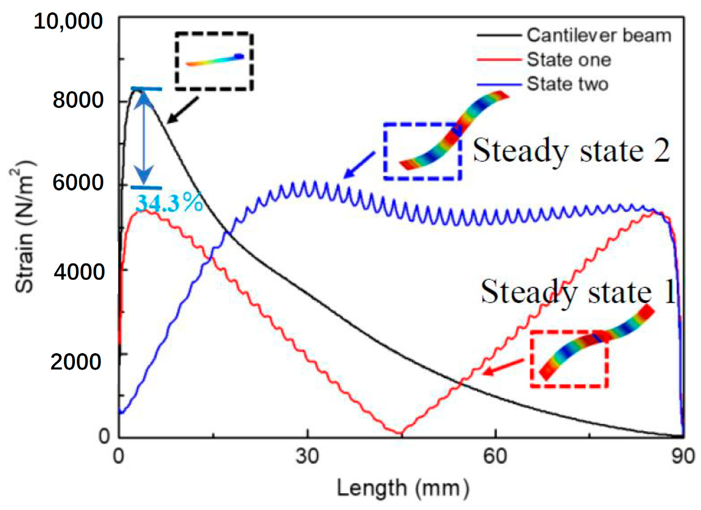
To solve the above problems, the finite element method (FEM) method is used to compare and calculate the stress changes of the cantilever beam and the S-type generator beam of the energy harvester proposed in this paper during the movement. When the two forms of generating beam reach their own resonant frequencies, the maximum stress curve of the generating beam during the movement is shown in Figure 3. The cantilever beam appears obvious stress concentration phenomenon in the movement process, and the position of stress concentration remains unchanged, even if the beam moves; In contrast, the position of the peak stress of the S-type generator beam proposed in this paper is constantly moving with the change of the movement process (from steady state 1 to steady state 2), which can make full use of materials to avoid premature fatigue failure of materials caused by stress concentration. In addition, as far as the peak stress is concerned, the peak stress of the S-type generator beam is 34.3% lower than that of the cantilever beam, which shows the great potential of the S-type generator beam in improving the fatigue failure of materials.

4. Experiments and Analysis

4.1. Energy Harvester Design of the S-Type Generator Beam in Different Environment

Low frequency vibration energy exists widely in various environments. Because the S-type generator beam proposed in this paper can be used in the design of energy harvesting devices in different environments, it has a broad application prospect. Thus, two typical operating environments, the up-and-down vibration excitation and the wind-induced vibration excitation, are presented in this paper as energy harvester designs for the application of S-beam.
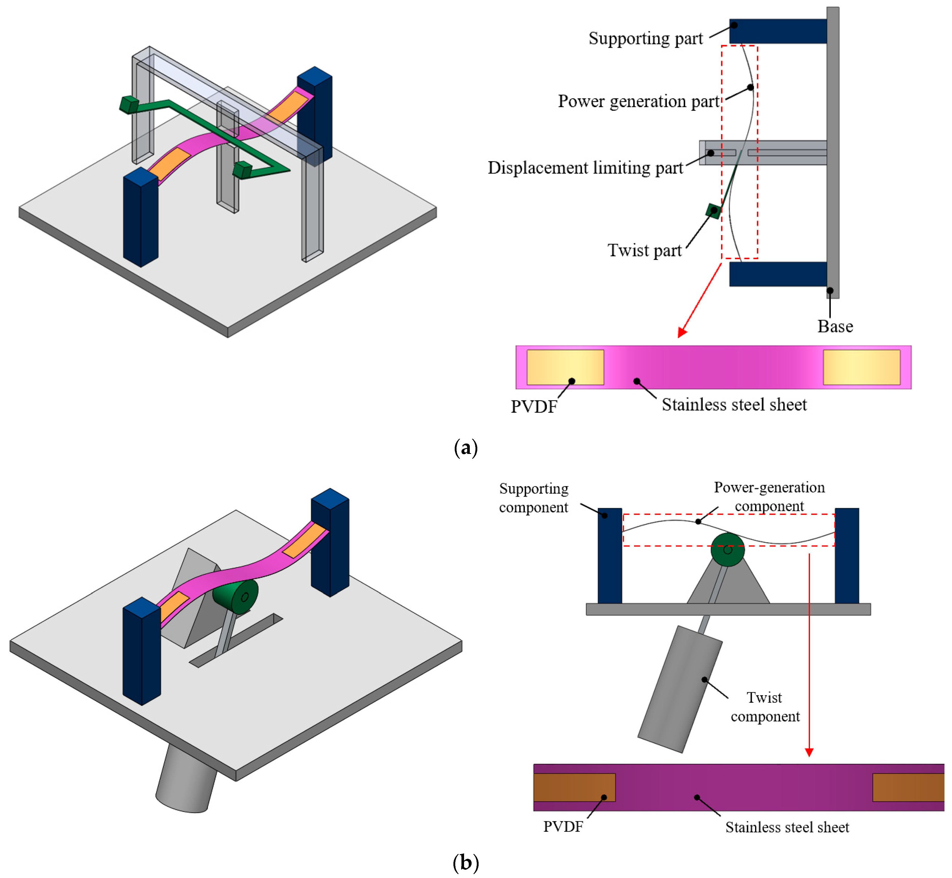
To drive the beam, the energy harvester is designed to provide suitable torque to the middle of the S-beam. As shown in Figure 4a, a “U”-shaped torsional beam is designed to be bonded in the middle of the generator beam in the up and down vibration excitation environment. The torsional beam absorbs the vibration excitation in the environment and converts it into the torque applied in the middle of the generator beam, driving the generator beam to move and generate electric energy. Thus, in addition to the design of supporting parts (the base and columns), the energy harvester also has a limit device in the middle of the beam to ensure that the beam moves in the desired way. The base of the “S”-type power generation beam is made of 301 stainless steel with a thickness of 0.1 mm. The two ends of the power generation beam are pasted with PVDF piezoelectric plates to convert motion energy into electric energy.
In a windy environment, an appropriate bluff body can be utilized to accomplish the energy transfer from fluid to solid. It is known that, within a certain speed range, the wind passing through a cylinder forms alternated vortices shedding at the backside of the cylinder and then the cylinder is affected by VIV (vortex-induced vibration). This principle has been utilized in the design of the energy harvester, as shown in Figure 4b. A rotation bearing is rigidly connected at the midpoint of the S-shaped power beam and one end of the rigid rod with a cylindrical (aerodynamic) shape is connected to the bearing. As such, the wind passing through the energy harvester will turn the vortex-induced forces received by the cylindrical rods into the torsion received in the mid part of the generator beam, thereby driving the beam’s motion. Thus, the wind energy will be converted into a torque received in the middle of the generating beam due to the vortex-induced forces applied by the cylindrical element, driving the generator beam’s motion.

4.2. Prototype Fabrication and Experimental Setup

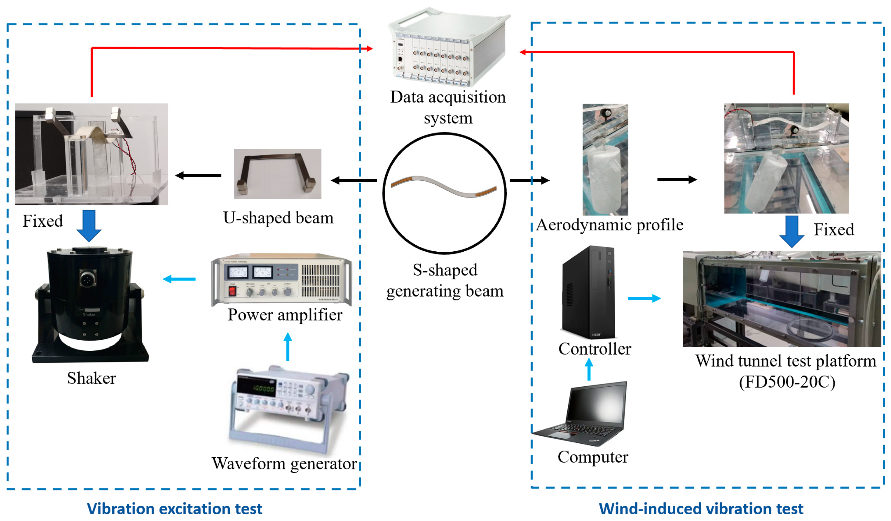
Two prototypes were fabricated and tested under different vibration conditions, as shown in Figure 5. The “S”-shaped power-generating beam of the harvester is embedded in the middle of the limiting module, with PVDF Piezoelectric Film (IPS-17020) attached to the surface of a steel piece (Steel Model: 301), which has a thickness of 0.1 mm. PMMA (Polymeric Methyl Methacrylate) is used as the material for the base, column, and limiting module in the prototype production. The U-shaped torsional beam in the up-and-down vibration energy harvester is made of 301 steel with a thickness of 0.5 mm, and the end mass block’s weight is 10 g. Additionally, the design of the blocking fluid in the cylindrical flow retarder (Φ60 × 150 mm), made of Polystyrene foam, is vital for absorbing wind field energy by VIV, thus being the key to the successful design of a wind-induced vibration energy harvester.
As shown in Figure 5, the SA-SG030 model signal generator is employed to output waveform signals to the SA-JZ020 model shaker to conduct up-and-down vibration excitation on the energy harvester. Moreover, the FD500-20C model ring return wind tunnel experimental platform provides the test environment for the other energy harvester. The Data Acquisition Instrument (DH5922 model) and the Laser Displacement Meter (HG-C1200 model) are responsible for obtaining voltage output signals and movement displacement signals, respectively, during the energy harvester test process.

4.3. Voltage Frequency Response Analysis

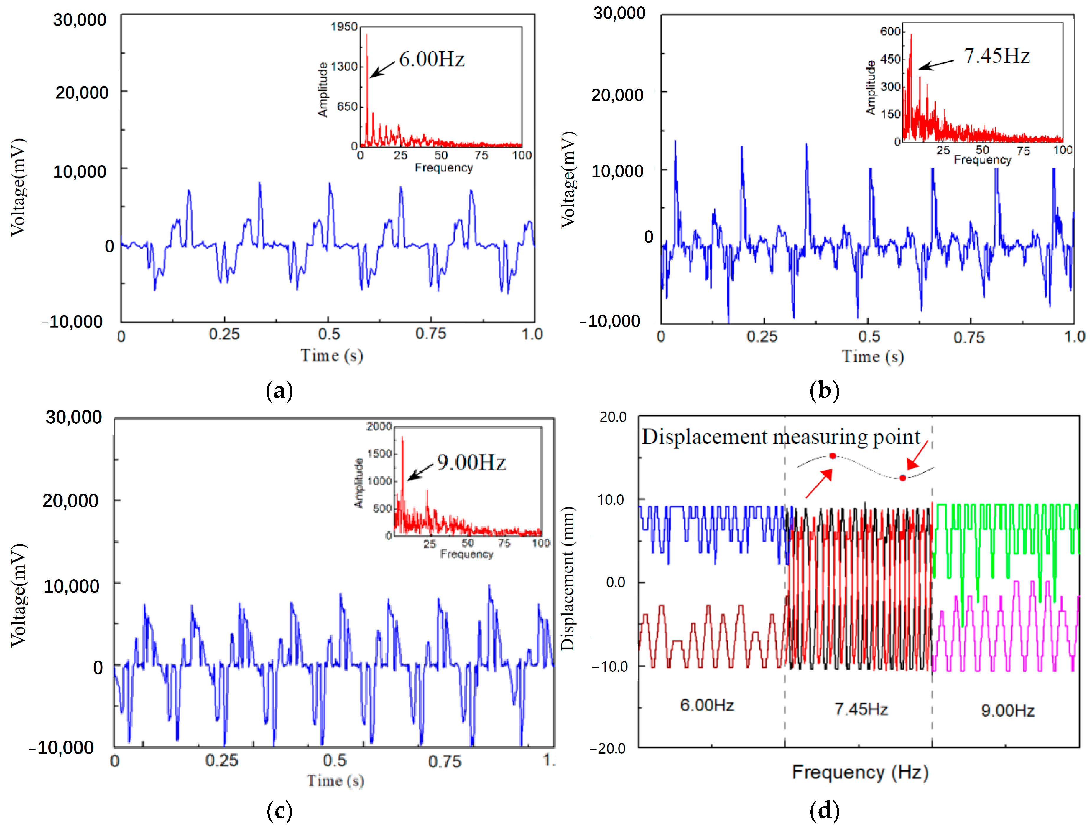
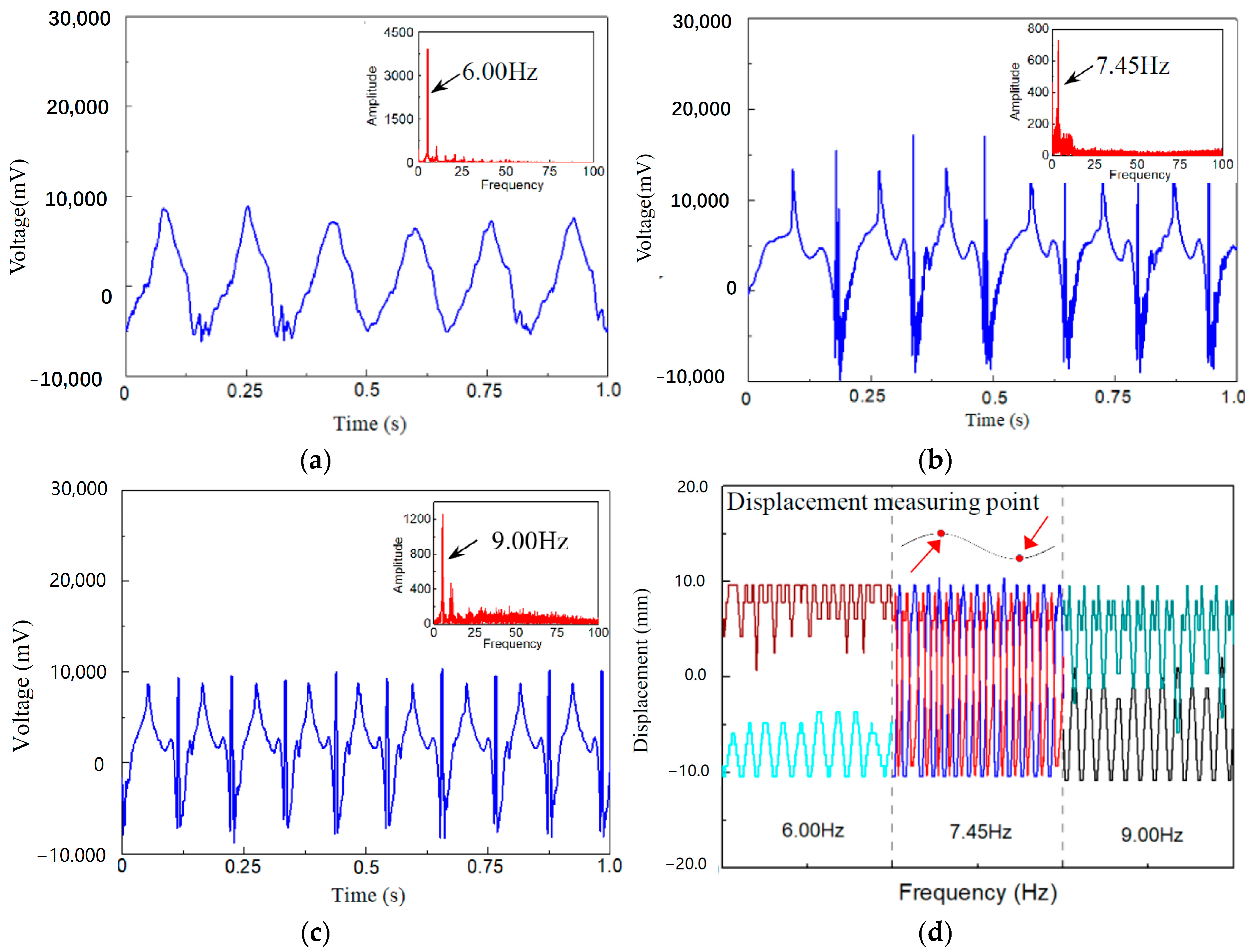
In order to comprehensively evaluate the performance of the S-type generator beam in two environments (The up-and-down vibration excitation and the wind-induced vibration excitation), a specific mode (3st mode, 7.45 Hz) and a typical low-frequency environmental excitation (6.0 Hz and 9.0 Hz) are applied to the two energy harvesters containing the S-type generator beam. The experimental results are shown in Figure 6 and Figure 7.
In the up-and-down vibration excitation environment, when the excitation frequency is 6 Hz, the output peak voltage of the generator beam is 8790 mV (Figure 6a). At this time, the generator beam fails to break through the potential energy barrier and only moves within the well. The above conclusion can be drawn from the displacement data of the two motion observation points set on the generator beam, as shown in Figure 6d. When the environmental excitation frequency rises to the third natural frequency (3rd mode, 7.45 Hz) of the S-type generator beam, the motion state of the beam changes obviously, mainly manifested in the motion process of the beam breaking through the potential energy barrier and generating inter-well movement (snap-through). The amplitude increases substantially, and some local high-frequency vibration occurs at the same time (Figure 6d). Thus, in terms of voltage output, the peak voltage is increased to 14,350 mV, resulting in increased burrs in the voltage curve due to local high-frequency vibration. When the ambient excitation frequency continues to increase to 9.0 Hz, the motion state of the beam changes from inter-well motion to in-well motion again, as shown in Figure 6d. At this time, the amplitude is slightly larger than that of the excitation frequency of 6 Hz but far smaller than that of the resonant frequency 7.45 Hz, and the peak voltage output at this time is 8680 mV (Figure 6c).
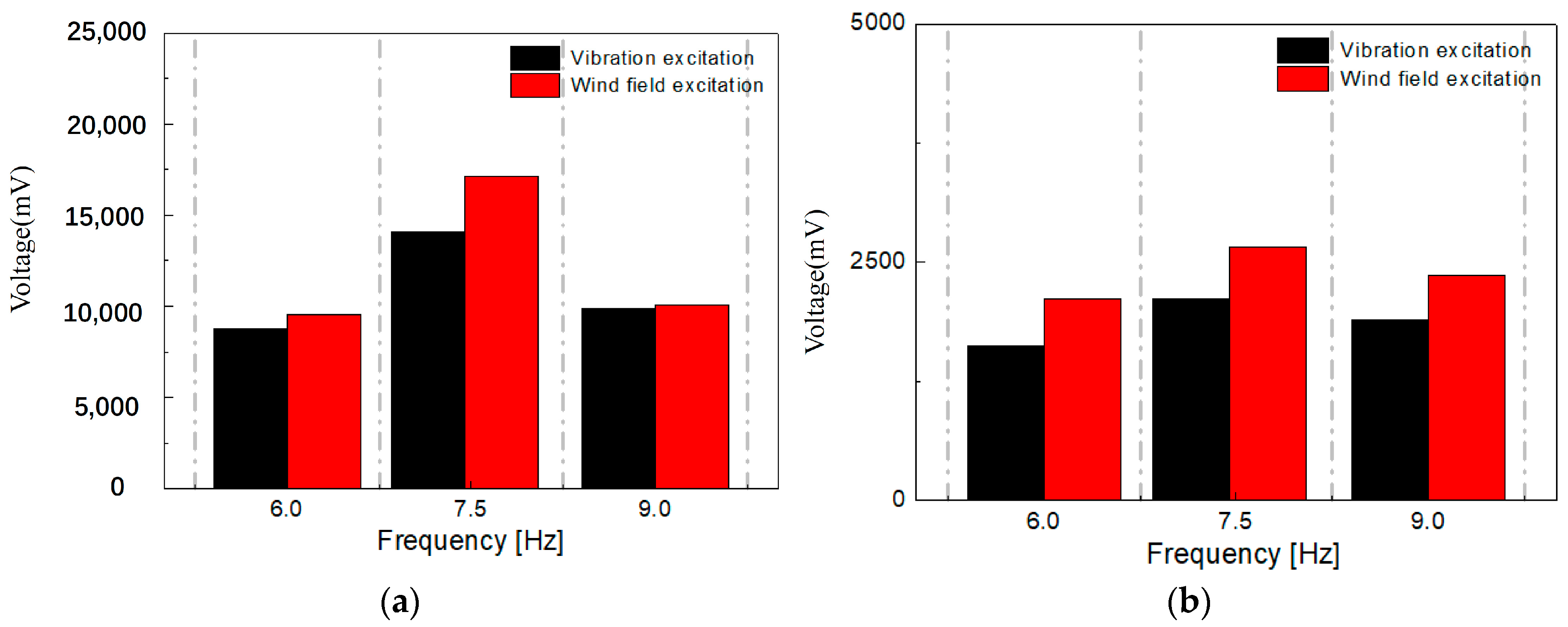
In the condition of the wind-induced vibration excitation, when the environmental excitation frequency reaches 6.0 Hz, 7.45 Hz and 9.0 Hz respectively, the motion variation law of S-type generator beam is similar to the above-mentioned law of the up-and-down vibration excitation, as shown in Figure 7. At this condition, the peak output voltage is 9610 mV, 17,630 mV and 10,020 mV respectively. Compared with the up-and-down vibration excitation, both the peak value and average value of the output voltage of the generator beam at the condition of wind-induced vibration are slightly larger (as shown in Figure 8). This is because the vorticity induced by the alternating vortex behind the blocked fluid can more effectively act on the middle of the generator beam in the form of torque in the wind environment.

4.4. Output Performance of Two Kinds of Harvester in Different Environments

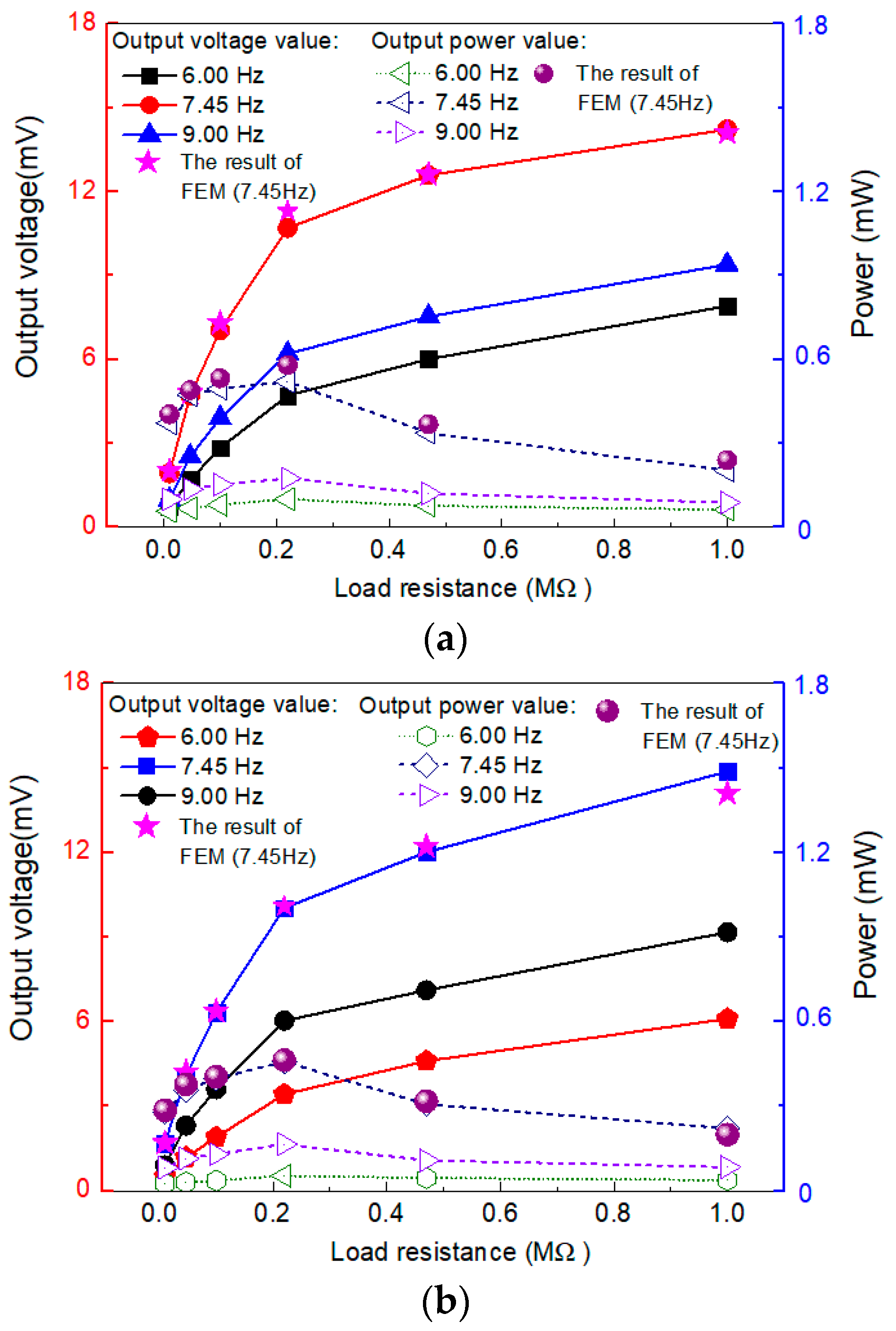
The energy harvesting performance of two types of energy harvesters in different environments was evaluated separately, as shown in Figure 9. The solid curves in the figure correspond to the voltage signal (left axis), and the curves with hollow points correspond to the average output power (right axis). Under the condition of up-and-down vibration excitation (Figure 9a), the peak value of circuit output voltage increases with the increase of load resistance, while the peak output power shows a trend of initially increasing and then decreasing. Within the experimental range, when the external resistance of the circuit is 22 kΩ, the peak output power of the circuit reaches a maximum state of 0.534 mW (7.45 Hz). In the condition of wind-induced vibration excitation (Figure 9b), the power output of the energy harvester showed the same variation pattern, with a peak power value of 0.545 mW. The natural frequency of the energy harvester structure and the properties of the PVDF (capacitance) determine the optimum load resistance value to be used during the testing of the device [42]. The average power Pavg is calculated as P a v g = V 2 r m s R , where V r m s = 1 T 2 T 1 T 1 T 2 V 2 d t denotes the root mean square (RMS) voltage (Vrms). (where V is the voltage and R is the resistance). The conclusion is that, as the external resistance value of the circuit increases, the output power of the energy harvester in both environments first increases, then reaches a maximum when the external resistance reaches 22 kΩ, and eventually decreases.
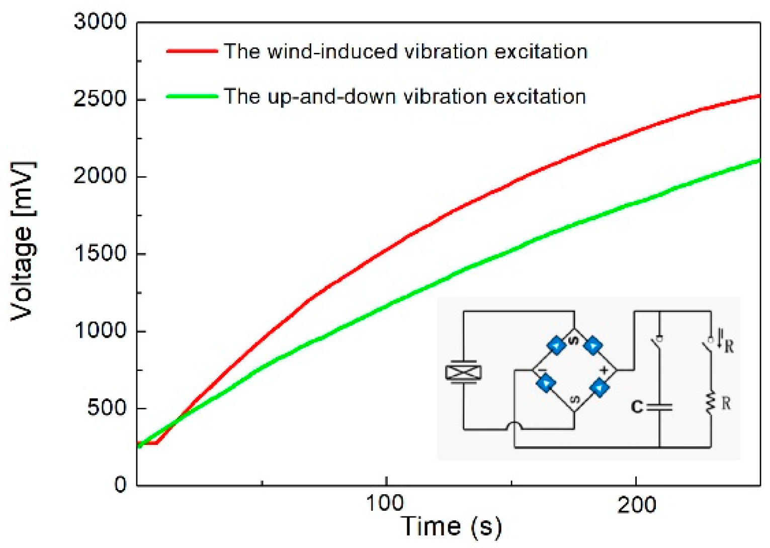
To verify the energy harvesting capability of the two energy harvesters, a 470 μF capacitor was used to collect energy with an excitation frequency of 7.45 Hz. A full bridge circuit to change alternating current (AC) to direct current (DC), as shown in Figure 10. After 100 seconds of charging, the capacitor voltage reached 1210 mV with the energy harvester at up-down excitation environment (7.45 Hz), and the capacitor charging voltage with the energy harvester at wind excitation environment (7.45 Hz) increased by 26.4% to 1530 mV. Further, after 200 seconds of charging (7.45 Hz), the capacitor voltages are 1820 mV and 2290 mV, respectively. In the same environmental excitation frequency, the energy harvester efficiency of the S-type generator beam in a wind environment is better than that of up-and-down vibration excitation environment. This is because in wind environment, the force of VIV received by the blocking fluid can be more fully transmitted to the middle of S-type generator beam in the form of torque, resulting in more high-frequency vibration.

5. Conclusions

In summary, the S-type bistable generator beam is proposed, and energy harvesters using this beam in two typical environments (the up-and-down vibration excitation and the wind-induced vibration excitation) are designed, prototyped, and tested in order to assess its suitability for energy harvesting from broadband vibrations. Here are some important conclusions:
  • This research paper proposes an S-type generator beam which can fully utilize materials and avoid premature fatigue failure caused by stress concentration. Under the same excitation conditions, the peak stress of the S-type generator beam is 34.3% lower than that of the cantilever beam (in the optimal working condition), indicating the advanced technology of the S-type generator beam in improving material fatigue failure.
  • The S-type generator beam has good energy capture performance in low-frequency environments. A collector using S-type bistable generator beam was tested in two typical environments. When the environmental excitation frequency rises to the third natural frequency (the third mode, 7.45 Hz) of the generator beam, the motion process of the beam breaks through the potential energy barrier and produces intrawell motion (penetration). The peak output voltage in the two environments is 14,350 mV and 17,630 mV, respectively.
  • The S-type generator beam has a high energy capture efficiency. Within the experimental range, when the external resistance of the circuit is 22 kΩ, the energy collector in both environments reaches the optimal power output state, which is 0.534 mW and 0.545 mW, respectively. At this time, the AC-to-DC bridge circuit sends power to a 470 μF capacitor, and the energy collector is better in the wind environment than in the up-down vibration environment.

Author Contributions

Conceptualization, N.W.; methodology, N.W.; software, N.W.; validation, N.W.; formal analysis, C.X.; investigation, C.X.; resources, J.F.; data curation, C.X.; writing—original draft preparation, N.W.; writing—review and editing, N.W.; visualization, J.F.; supervision, J.F.; project administration, J.F.; funding acquisition, J.F. All authors have read and agreed to the published version of the manuscript.

Funding

This research was funded by National Science Fund for Distinguished Young Scholars grant number [51925802]; the National Natural Science Foundation of China grant number 11972123; 52108448] and The APC was funded by [11972123].

Institutional Review Board Statement

Not applicable.

Informed Consent Statement

Not applicable.

Data Availability Statement

The introduction data supporting this manuscript are from previously reported studies and datasets, which have been cited. The processed data are available from the corresponding author upon request. The test raw data used to support the findings of this study are available from the corresponding author upon request.

Acknowledgments

The authors would like to thank the National Science Fund for Distinguished Young Scholars (Grant No. 51925802), and the National Natural Science Foundation of China (Grant No. 11972123; Grant No. 52108448) and the for their financial support.

Conflicts of Interest

We declare that we do not have any commercial or associated interest that might represent a conflict of interest in connection with the work submitted.

References

  1. Shaikh, F.K.; Zeadally, S. Energy harvesting in wireless sensor networks: Acomprehensive review, Renew. Sustain. Energy Rev. 2016, 55, 1041–1054. [Google Scholar] [CrossRef]
  2. Harne, R.L.; Wang, K.W. A review of the recent research on vibration energy harvesting via bistable systems. Smart Mater. Struct. 2013, 22, 023001. [Google Scholar] [CrossRef]
  3. Priya, S.; Song, H.-C.; Zhou, Y.; Varghese, R.; Chopra, A.; Kim, S.-G.; Kanno, I.; Wu, L.; Ha, D.S.; Ryu, J.; et al. A review on piezoelectric energy harvesting: Materials, methods, and circuits. Energy Harvest. Syst. 2019, 4, 3–39. [Google Scholar] [CrossRef]
  4. Yang, B.; Lee, C.; Xiang, W.; Xie, J.; He, J.H.; Kotlanka, R.K.; Low, S.P.; Feng, H. Electromagnetic energy harvesting from vibrations of multiple frequencies. J. Micromech. Microeng. 2009, 19, 035001. [Google Scholar] [CrossRef]
  5. Crovetto, A.; Wang, F.; Hansen, O. Modeling and optimization of an electrostatic energy harvesting device. J. Microelectromech. Syst. 2014, 23, 1141–1155. [Google Scholar] [CrossRef]
  6. Wang, Z.L.; Chen, J.; Lin, L. Progress in triboelectric nanogenerators as a new energy technology and self-powered sensors. Energy Environ. Sci. 2015, 8, 2250–2282. [Google Scholar] [CrossRef]
  7. Bowen, C.R.; Kim, H.A.; Weaver, P.M.; Dunn, S. Piezoelectric and ferroelectric materials and structures for energy harvesting applications. Energy Environ. Sci. 2013, 7, 25–44. [Google Scholar] [CrossRef]
  8. Farhangdoust, S.; Mehrabi, A.; Younesian, D. Bistable wind-induced vibration energy harvester for self-powered wireless sensors in smart bridge monitoring systems. In Proceedings of the Nondestructive Characterization and Monitoring of Advanced Materials, Aerospace, Civil Infrastructure, and Transportation XIII, Denver, CO, USA, 4–7 March 2019. [Google Scholar] [CrossRef]
  9. Kan, J.; Liao, W.; Wang, J.; Wang, S.; Yan, M.; Jiang, Y.; Zhang, Z. Enhanced piezoelectric wind-induced vibration energy harvester via the interplay between cylindrical shell and diamond-shaped baffle. Nano Energy 2021, 89, 106466. [Google Scholar] [CrossRef]
  10. Wu, N.; He, Y.; Fu, J.; Liao, P. Performance of a bistable flow-energy harvester based on vortex-induced vibration. J. Wind Eng. Ind. Aerodyn. 2021, 217, 104733. [Google Scholar] [CrossRef]
  11. Zhou, J.; Zhao, X.; Wang, K.; Chang, Y.; Xu, D.; Wen, G. Bio-inspired bistable piezoelectric vibration energy harvester: Design and experimental investigation. Energy 2021, 228, 120595. [Google Scholar] [CrossRef]
  12. Peng, Y.; Xu, Z.; Wang, M.; Li, Z.; Peng, J.; Luo, J.; Xie, S.; Pu, H.; Yang, Z. Investigation of frequency-up conversion effect on the performance improvement of stack-based piezoelectric generators. Renew. Energy 2021, 172, 551–563. [Google Scholar] [CrossRef]
  13. Nan, W.; Yuncheng, H.; Jiyang, F. Bistable energy harvester using easy snap-through performance to increase output power. Energy 2021, 226, 120414. [Google Scholar] [CrossRef]
  14. Umeda, M.; Nakamura, K.; Ueha, S. Analysis of the Transformation of Mechanical Impact Energy to Electric Energy Using Piezoelectric Vibrator. Jpn. J. Appl. Phys. 1996, 35, 3267. [Google Scholar] [CrossRef]
  15. Fu, H.; Sharif-Khodaei, Z.; Aliabadi, F. A bio-inspired host-parasite structure for broadband vibration energy harvesting from low-frequency random sources. Appl. Phys. Lett. 2019, 114, 143901. [Google Scholar] [CrossRef]
  16. Shin, Y.-H.; Choi, J.; Kim, S.J.; Kim, S.; Maurya, D.; Sung, T.-H.; Priya, S.; Kang, C.-Y.; Song, H.-C. Automatic resonance tuning mechanism for ultra-wide bandwidth mechanical energy harvesting. Nano Energy 2020, 77, 104986. [Google Scholar] [CrossRef]
  17. Kouritem, S.A.; Bani-Hani, M.A.; Beshir, M.; Elshabasy, M.M.Y.B.; Altabey, W.A. Automatic Resonance Tuning Technique for an Ultra-Broadband Piezoelectric Energy Harvester. Energies 2022, 15, 7271. [Google Scholar] [CrossRef]
  18. Rezaei, M.; Talebitooti, R.; Liao, W.-H. Investigations on Magnetic Bistable PZT-Based Absorber for Concurrent Energy Harvesting and Vibration Mitigation: Numerical and Analytical Approaches. Energy 2022, 239, 122376. [Google Scholar] [CrossRef]
  19. Saint-Martin, C.; Morel, A.; Charleux, L.; Roux, E.; Benhemou, A.; Badel, A. Power Expectation as a Unified Metric for the Evaluation of Vibration Energy Harvesters. Mech. Syst. Signal Process. 2022, 181, 109482. [Google Scholar] [CrossRef]
  20. Chiacchiari, S.; Romeo, F.; McFarland, D.M.; Bergman, L.A.; Vakakis, A.F. Vibration Energy Harvesting from Impulsive Excitations via a Bistable Nonlinear Attachment—Experimental Study. Mech. Syst. Signal Process. 2019, 125, 185–201. [Google Scholar] [CrossRef]
  21. Huguet, T.; Badel, A.; Druet, O.; Lallart, M. Drastic Bandwidth Enhancement of Bistable Energy Harvesters: Study of Subharmonic Behaviors and Their Stability Robustness. Appl. Energy 2018, 226, 607–617. [Google Scholar] [CrossRef]
  22. Andó, B.; Baglio, S.; Maiorca, F.; Trigona, C. Two Dimensional Bistable Vibration Energy Harvester. Procedia Eng. 2012, 47, 1061–1064. [Google Scholar] [CrossRef]
  23. Harne, R.L.; Zhang, C.; Li, B.; Wang, K.W. An Analytical Approach for Predicting the Energy Capture and Conversion by Impulsively-Excited Bistable Vibration Energy Harvesters. J. Sound Vib. 2016, 373, 205–222. [Google Scholar] [CrossRef]
  24. Syta, A.; Bowen, C.R.; Kim, H.A.; Rysak, A.; Litak, G. Responses of Bistable Piezoelectric-Composite Energy Harvester by Means of Recurrences. Mech. Syst. Signal Process. 2016, 76–77, 823–832. [Google Scholar] [CrossRef]
  25. Derakhshani, M.; Momenzadeh, N.; Berfield, T.A. Analytical and Experimental Study of a Clamped-Clamped, Bistable Buckled Beam Low-Frequency PVDF Vibration Energy Harvester. J. Sound Vib. 2021, 497, 115937. [Google Scholar] [CrossRef]
  26. Sosna, P.; Rubeš, O.; Hadaš, Z. Verification and Analysis of Advanced Tuneable Nonlinear Vibration Energy Harvester. Mech. Syst. Signal Process. 2023, 189, 110096. [Google Scholar] [CrossRef]
  27. Andò, B.; Baglio, S.; Maiorca, F.; Trigona, C. Analysis of Two Dimensional, Wide-Band, Bistable Vibration Energy Harvester. Sens. Actuators A Phys. 2013, 202, 176–182. [Google Scholar] [CrossRef]
  28. Tan, D.; Zhou, J.; Wang, K.; Ouyang, H.; Zhao, H.; Xu, D. Sliding-Impact Bistable Triboelectric Nanogenerator for Enhancing Energy Harvesting from Low-Frequency Intrawell Oscillation. Mech. Syst. Signal Process. 2023, 184, 109731. [Google Scholar] [CrossRef]
  29. Naseer, R.; Abdelkefi, A. Nonlinear Modeling and Efficacy of VIV-Based Energy Harvesters: Monostable and Bistable Designs. Mech. Syst. Signal Process. 2022, 169, 108775. [Google Scholar] [CrossRef]
  30. Huguet, T.; Lallart, M.; Badel, A. Orbit Jump in Bistable Energy Harvesters through Buckling Level Modification. Mech. Syst. Signal Process. 2019, 128, 202–215. [Google Scholar] [CrossRef]
  31. Cao, D.-X.; Lu, Y.-M.; Lai, S.-K.; Mao, J.-J.; Guo, X.-Y.; Shen, Y.-J. A novel soft encapsulated multi-directional and multi-modal piezoelectric vibration energy harvester. Energy 2022, 254, 124309. [Google Scholar] [CrossRef]
  32. Song, J.; Xia, C.; Shan, G.; Wang, Z.; Ono, T.; Wang, D.F. Widening frequency bandwidth with parametric coupling in a wings-inspired low frequency MEMS energy harvester. Energy Convers. Manag. 2022, 267, 115924. [Google Scholar] [CrossRef]
  33. Wang, J.; Liao, W.-H.; Cao, J. Power enhancement of a monostable energy harvester by orbit jumps. J. Intell. Mater. Syst. Struct. 2021, 32, 2601–2614. [Google Scholar] [CrossRef]
  34. Hou, C.; Zhang, X.; Yu, H.; Shan, X.; Sui, G.; Xie, T. Ori-inspired bistable piezoelectric energy harvester for scavenging human shaking energy: Design, modeling, and experiments. Energy Convers. Manag. 2022, 271, 116309. [Google Scholar] [CrossRef]
  35. Qian, F.; Hajj, M.R.; Zuo, L. Bio-inspired bi-stable piezoelectric harvester for broadband vibration energy harvesting. Energy Convers. Manag. 2020, 222, 113174. [Google Scholar] [CrossRef]
  36. Zhou, Z.; Qin, W.; Zhu, P.; Shang, S. Scavenging wind energy by a Y-shaped bi-stable energy harvester with curved wings. Energy. 2018, 153, 400–412. [Google Scholar] [CrossRef]
  37. Usman, M.; Hanif, A.; Kim, I.-H.; Jung, H.-J. Experimental validation of a novel piezoelectric energy harvesting system employing wake galloping phenomenon for a broad wind spectrum. Energy. 2018, 153, 882–889. [Google Scholar] [CrossRef]
  38. Wu, R.; Zhou, C. Design and Experimental Study of Two-Stage Flexible Flapping Wing Air Vehiicle. Master’s Thesis, Harbin Institute of Technology, Harbin, China, 2019. [Google Scholar] [CrossRef]
  39. Li, H.; Ding, H.; Chen, L. Chaotic dynamics of a bi-stable energy harvesting system with asymmetric potential well characteristics. J. Vib. Shock. 2020, 39, 54–59+69. [Google Scholar] [CrossRef]
  40. Avvari, P.V.; Yang, Y.; Soh, C.K. Long-term fatigue behavior of a cantilever piezoelectric energy harvester. J. Intell. Mater. Syst. Struct. 2017, 28, 1188–1210. [Google Scholar] [CrossRef]
  41. Yi, Z.; Hu, Y.; Ji, B.; Liu, J.; Yang, B. Broad bandwidth piezoelectric energy harvester by a flexible buckled bridge. Appl. Phys. Lett. 2018, 113, 183901. [Google Scholar] [CrossRef]
  42. Zhang, L.B.; Dai, H.L.; Abdelkefi, A.; Wang, L. Experimental investigation of aerodynamic energy harvester with different interference cylinder cross-sections. Energy 2019, 167, 970–981. [Google Scholar] [CrossRef]
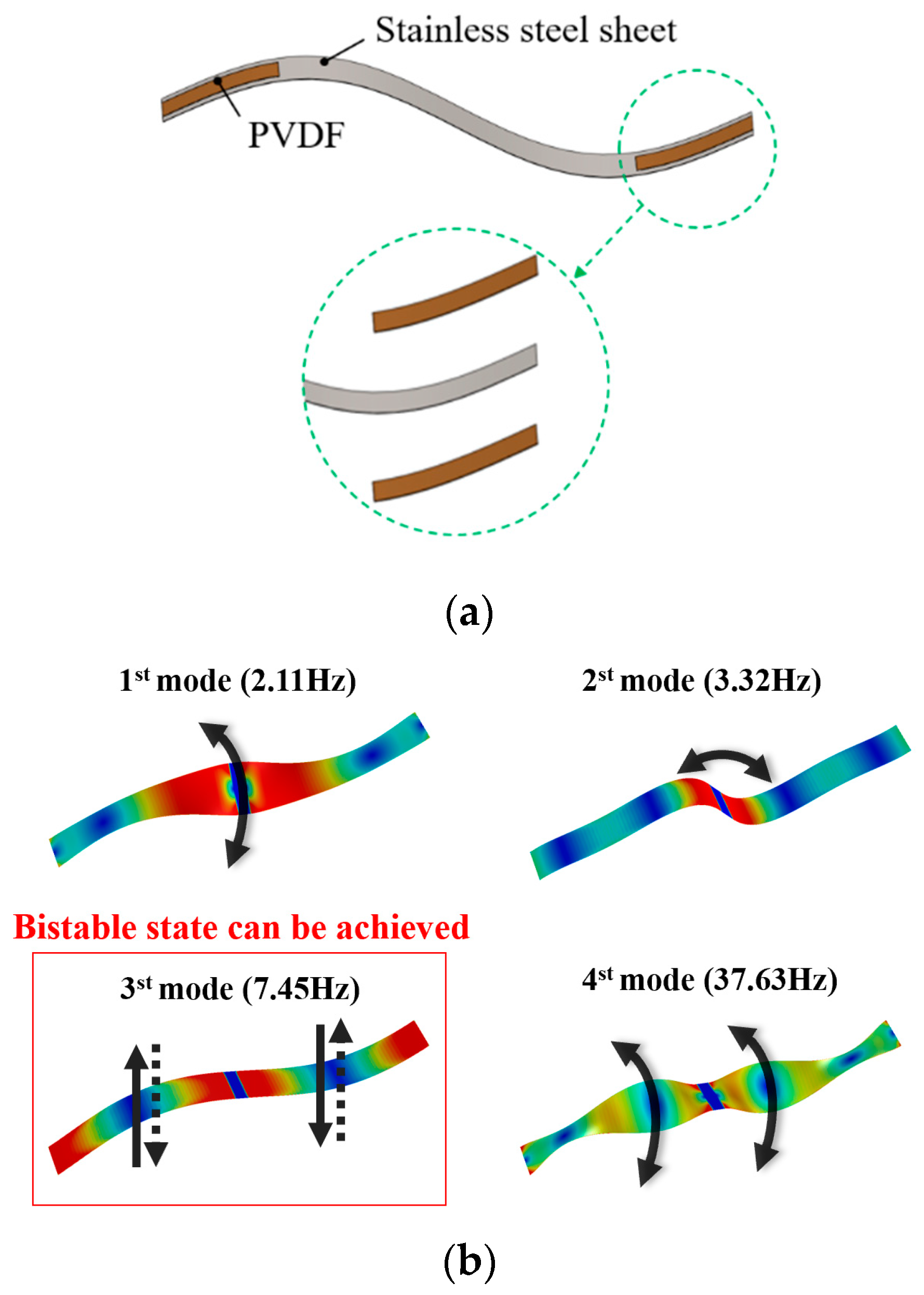
Figure 1. The “S” type bistable power generation beam: (a) Design sketches of structure composition; (b) Modal properties of the beam; (c) Steady state of the beam.
Applsci 13 05258 g001aApplsci 13 05258 g001b
Figure 2. The motion state (normalized) of the generating beam at different potential well heights: (a) h = 5 mm; (b) h = 10 mm; (c) h = 15 mm.
Applsci 13 05258 g002
Figure 3. The stress distribution of the generator beam during movement (inter-well motion).
Applsci 13 05258 g003
Figure 4. Design sketches of the energy harvester at different excitation conditions: (a) The up-and-down vibration excitation; (b) The wind-induced vibration excitation.
Applsci 13 05258 g004
Figure 5. Experimental prototype and set-up.
Applsci 13 05258 g005
Figure 6. Test results of vibration excitation: (a) F = 6 Hz (The excitation frequency); (b) F = 7.45 Hz; (c) F = 9.00 Hz; (d) Displacement of two vaults of generator beam at different excitation frequencies (Different colors enhance visual comparison of measurements at different positions/frequencies).
Applsci 13 05258 g006
Figure 7. Test results of wind field excitation: (a) F = 6 Hz (The excitation frequency); (b) F = 7.45 Hz; (c) F = 9.00 Hz; (d) Displacement of two vaults of generator beam at different excitation frequencies (Different colors enhance visual comparison of measurements at different positions/frequencies).
Applsci 13 05258 g007
Figure 8. The voltage signal histogram of the harvester: (a) Peak histogram; (b) Mean histogram.
Applsci 13 05258 g008
Figure 9. The output performance of the harvester at different circuit load conditions: (a) The up-and-down vibration excitation; (b) The wind-induced vibration excitation.
Applsci 13 05258 g009
Figure 10. The output performance through a rectifier circuit.
Applsci 13 05258 g010
Disclaimer/Publisher’s Note: The statements, opinions and data contained in all publications are solely those of the individual author(s) and contributor(s) and not of MDPI and/or the editor(s). MDPI and/or the editor(s) disclaim responsibility for any injury to people or property resulting from any ideas, methods, instructions or products referred to in the content.