Article

Optimization of Damping in a Semi-Active Car Suspension System with Various Locations of Masses

1
Department of Mechatronics, Robotics and Digital Manufacturing, Faculty of Mechanics, Vilnius Gediminas Technical University, Plytinės g. 25, LT-10105 Vilnius, Lithuania
2
Center for Physical Sciences and Technology, Saulėtekio al. 3, LT-10257 Vilnius, Lithuania
*
Author to whom correspondence should be addressed.
Appl. Sci. 2023, 13(9), 5371; https://doi.org/10.3390/app13095371
Submission received: 20 March 2023 / Revised: 19 April 2023 / Accepted: 19 April 2023 / Published: 25 April 2023

Abstract

:
The key request for a vehicle suspension system is vibration control and decreasing the actual inertia forces. This ensures ride comfort for the crew and influences the fatigue level of the driver and overall driving safety. Implementing semi-active damping control in the vehicle suspension allows for adjusting the damping process in the vehicle for minimum acceleration applied to the seats, driver, and passengers. In order to implement theoretical analysis, we used a mathematical full-car model in Simulink/MATLAB. As the load, we added simulations of various artificially generated road profiles. The damping coefficient of the semi-active suspension system was optimized for maximum comfort level for a driver only. Results from the full-car simulation process deliver a graph of the output accelerations showing kinematic excitation from road deformities under various locations of vehicle load positions.

1. Introduction

The wheels are connected to the vehicle through the suspension system. In real vehicle suspensions, the relative movement of the wheels in relation to the vehicle body is used for vibration control and for the transmission of force and torque between the wheels and body. Vibration control helps hold good and uninterrupted contact of the tires with the road and ensures driving safety and ride comfort regardless of the quality of the road surface [1]. Depending on vibration control, the suspension types are passive, semi-active, and fully active. Semi-active suspension can smoothly change the damping coefficient and can be nearly as effective as a fully-active suspension for increasing ride quality [2]. It combines the advantages of both the other suspension types. Various systems are discussed in reference [3] noting their strengths, weaknesses, and relative performance or equipment requirements. The semi-active suspension system becomes a suitable choice due to its small power consumption, low expense, and fewer parameters [4]. The main element of semi-active suspensions is a variable damper of a few possible types: the magnetorheological damper, the electrorheological damper, the electrohydraulic damper, and the electromagnetic damper [5,6].
Road conditions often alter during driving. Different emphasis is placed on ride comfort and handling stability under different road conditions or driving styles [7,8,9]. The properties of the suspension should also change depending on the road conditions [10,11,12]. When ride comfort is the priority, a semi-active suspension system using a variable damper can have an effectiveness close to that of an active suspension [3,13,14,15,16]. However, the variable damper in a semi-active suspension system can only change the rate of dissipating energy without receiving energy, and it has major restrictions when one requires controlling the height and attitude movement of a vehicle. The semi-active suspension system with variable stiffness can solve this problem [17,18,19]. Meanwhile, some authors use both a variable damper and stiffness [20,21,22,23]. Therefore, semi-active suspension systems are very helpful in enhancing ride comfort and vehicle handling capabilities. One of the main problems is to determine the control signal for the semi-active suspension. Various control strategies [6,24,25,26] have been developed in which the control signal is determined by the measurement of different parameters. Real-time control strategies such as skyhooks or groundhooks are common for semi-active vibration damping based on road statistical properties, i.e., an optimal damping ratio control [26]. In addition, a preview strategy was implemented to improve the behavior of semi-active systems. Therefore, the system needs information about road conditions.
At present, researchers have carried out many studies of models and methods of road recognition. Some of them are difficult to realize or are very expensive. Various methods and equipment for measurement of the road properties are briefly discussed in [27,28,29]. Different, inexpensive response-based road profile identification methods are reviewed and presented in [30].
Several vehicle models with semi-active suspension systems have been commercially developed in recent years [6]. The usage of road profile information before a wheel hits road unevenness, investigated in [13,31,32,33,34,35], has been applied to mass production cars as well. The early attempts were made by Nissan in 1990 using Super Sonic Suspension [36] and, recently, the Magic Body Control feature [37] used in Mercedes Benz. H. Eric Tseng and Davor Hrovat in [38] state, “the next advances in active and semi-active suspension design will mainly come from two thrust areas. The first is the increased efficiency in actuator design and implementation such as the usage of systematic control software algorithm design combined with the previously mentioned innovative hardware design measures such as inclusion of possibly variable in-series/parallel compliances and fast load levelling. The second is more comprehensive usage of preview information from camera, Global Positioning System (GPS), and electronic horizon such as vehicle-to-vehicle communication, vehicle-to-infrastructure communication, vehicle localization and real-time accessing of cloud information, and crowd sourcing leading to up-to-date road profile maps”. So, there are still many areas for investigation [23,39,40,41,42,43].
We planned to keep in check our developed (semi-)active suspension [44] using information acquired from a segment of traveled road profile [45,46]. The central vehicle safety block would receive the road characteristics and set damper damping values to minimize the vibration of the vehicle body. The needed step is to relate the obtained road characteristics to the required optimal damping values. For that purpose, we needed a gridded matrix of damping coefficients at certain fixed values of speed and road characteristics. We found only a few papers with the results needed for this purpose; only a few points needed for the whole matrix can be found in them, and they used different car models, road types and characteristics, and optimization methods (see Table 1).
This paper provides a relationship between the detected w1, w2 waviness values for a wide range of road profiles and the optimized damping coefficient for a full-car model (12DOF) traveling them at various speeds. To minimize the number of possible choices, here we focus on instances when the damping coefficient was optimized for the maximum level of driver comfort. In addition, there are various locations of masses, and we used the same value of damping for all four wheels. This idea is similar to the developed method of minimizing the acceleration at a selected point on the vehicle body [54].

2. Methods

The random, artificial road profile can be generated through various methods, based on: (1) linear filtering, (2) superposition of harmonics, or (3) inverse fast Fourier transformation of discretized power spectra density (PSD) [55]. One of the most commonly implemented [56,57,58,59,60,61], the superposition of harmonics (or sinusoidal approximation), we also used. The longitudinal road profiles were generated using the original MATLAB code, implementing the method of superposition of harmonics in the spatial domain according to Equations (1) and (2):
z ( x ) = i = 1 N = ( Ω U Ω L ) / Δ Ω Z i cos ( Ω i x + φ i )   with
Z i = 2 G d ( Ω i ) Δ Ω
where N = ( Ω U Ω L ) / Δ Ω —number of harmonic samples (in our case, N = 1000); Ω U ,   Ω L —upper and lower angular spatial frequencies [rad/m] in the PSD spectrum; Δ Ω —the width of each frequency band; Z i —amplitude of the ith harmonic; Ω i = Ω L + ( i 1 ) Δ Ω —angular spatial frequency of the ith harmonic; φ i —phase angle of the ith harmonic uniformly distributed in the range from 0 to 2π; and G d ( Ω i ) —displacement PSD at angular spatial frequency Ω i . The ISO 8608 standard recommends the lower and upper limits of angular spatial frequencies (=2πn) equal to 2π × 0.01 rad/m and 2π × 10 rad/m for general on-road measurements, respectively [62]. To obtain various road profiles that more closely resemble real roads, we changed the linear fitting of G d ( Ω ) proposed by ISO [62] to two split fittings offered by Andrén [63] in Equation (2), and we modified it by reducing the amplitude of the frequencies higher than Ω2 and lower than 0.04 × 2π rad/m:
G d ( Ω ) = { G d ( Ω 0 ) Ω 1 G d ( Ω 0 ) Ω w 1 G d ( Ω 0 ) Ω w 2 G d ( Ω 0 ) Ω w 3 = 5 for for for for Ω 0.04 × 2 π rad / m 0.04 × 2 π rad / m Ω Ω 1 Ω 1 Ω Ω 2 Ω 2 Ω ,
where wi is waviness. The reference frequency Ω0 = 1 rad/m, the lower break frequency Ω1 = 0.21 × 2π rad/m, and the higher break frequency Ω2 = 1.22 × 2π rad/m produced a minimal error for the Swedish road network [63]. Additionally, a Welch-type windowing function with the value of the exponent equal to 10 was used to minimize the appearance of abrupt shifts at the connections between profile segments [64]. The profile generated in this way applied to the left side, and the profile for the right side was formed by randomly increasing or decreasing it by 20%. For comparison, identical sequences of random numbers were used to generate each profile.
The Range Rover Evoque dynamic response on road irregularities was analyzed on the full-car model. Our developed dynamic model included ten masses (the car’s mass; four wheels’ masses; and the masses of a driver, three passengers, and a baggage box) and moments of inertia about the X and Y axes [65]. This model is a dynamic system with twelve degrees of freedom: ten vertical displacements along the Z axis of the above-mentioned masses and rotation of the car body about the car’s center of mass around the X and Y axes. The model was built using Lagrange’s equation of the second type. These equations were solved analytically; after differentiating, the final system, consisting of twelve equations presented in this form, was obtained:
a i i q ˙ i + b i 1 q ˙ 1 + b i 2 q ˙ 2 + + b i n q ˙ n + c i 1 q 1 + c i 2 q 2 + + c i n q n = = d i 1 η 1 + d i 2 η 2 + d i 3 η 3 + d i 4 η 4 + d i 1 * η ˙ 1 + d i 2 * η ˙ 2 + d i 3 * η ˙ 3 + d i 4 * η ˙ 4
where a, b, c, d, and d* (with corresponding indexes) are coefficients of equations derived from matrixes of stiffness, dissipation, and inertia; q i is a generalized coordinate, in respect to which differentiation was applied during the building of a system of equations; n is the number of generalized coordinates; and η 1 ,   η 2 ,   η 3 ,   η 4 are coordinates along which the system of the car is excited kinematically. More information about our model, its derivation, and the parameters used can be found in reference [65]. Road irregularities are assumed in the model as the artificial road profiles. Both rear wheels pass the corresponding profiles shifted by a distance equal to the length between the front and rear wheel centers.
The same damping coefficient for all wheels, which defines the behavior of the suspension, was optimized to reach the minimal root-mean-square (RMS) value of driver vertical acceleration; in other words, the suspension system was adjusted for maximum driver comfort level. The mathematical solution of Equation (4) and the optimization process were processed using Simulink/MATLAB software and its response optimization.

3. Results and Discussion

Initially, the road profiles with various waviness w1 values of 1, 2, 4, and 6; w2 values of 0.5, 1, 2, and 3; and displacement PSD value G d ( Ω 0 ) = 4 × 10 6   m 3 [62] (ISO road class B) were generated. The length of the artificial road profile was 200 m. Finally, our dynamic full-car model simulated a vehicle passing these profiles at speeds v = 20, 50, 70, 90, and 130 km/h. Damping coefficient values can vary in the range from 1000 Ns/m up to 15,000 Ns/m. Most research authors studying suspension system optimization highlight three basic assessment touchstones related to minimization of the crew ride discomfort and changes in the tire contact with the road: (1) minimization of the standard deviation of sprung mass (body) acceleration, (2) minimization of the standard deviation of the normal reaction at the tire/road contact, and (3) reduction in the displacements of the suspension system [49,66,67]. In order to evaluate the ride comfort, statistics such as the suspension travel and sprung mass (body) acceleration [68], the standard deviation (RMS) of vertical acceleration [69,70], and the vertical jerk [71,72] are considered. The intuitive relationship between safety and comfort is contradictory [3], and a concurrent enhancement of both of them is not viable. In ref. [48] it is showed that the dependence of these parameters in some ranges of damping consistently grows and shrinks. In addition, a combined performance index with different weighting for each performance measure was used. The weightings depend on the intent of the design; for example, in the case of a luxury car, the highest weight is given to ride comfort. Thus, in this work, we considered only the vertical acceleration of the driver as a criterion for evaluation of the ride comfort, as in ref. [54]. All these optimizations were repeated for the seven masses: (1) m1 = m2 = m3 = m4 = 80 kg; (2) m1 = 80 kg; (3) m1 = m2 = 80 kg; (4) m1 = m3 = 80 kg; (5) m1 = m4 = 80 kg; (6) m1 = 160 kg; and (7) m1 = 100 kg, m2 = 60 kg, m3 = 50 kg, and m4 = 40 kg. The optimized suspension’s damping coefficient hs values for generated profiles and for all masses 80 kg are shown in Table 2, Figure 1a.
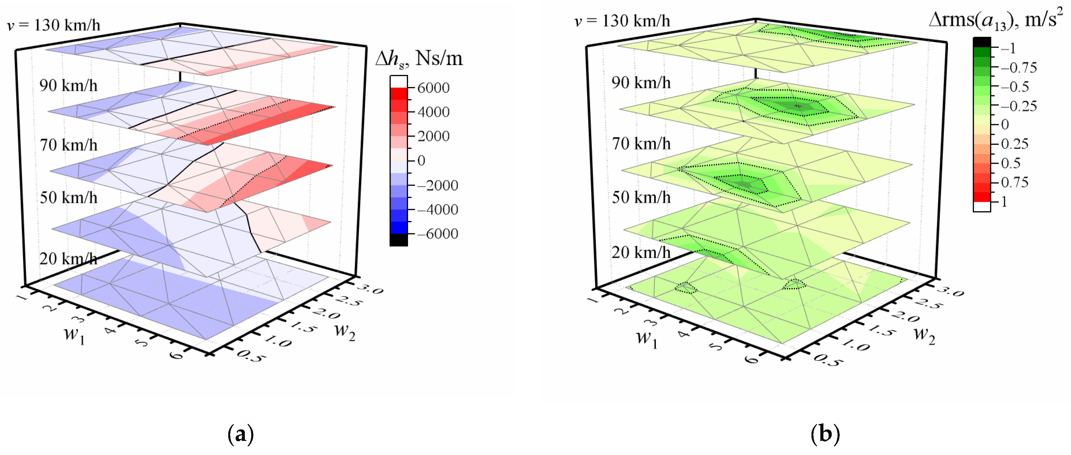
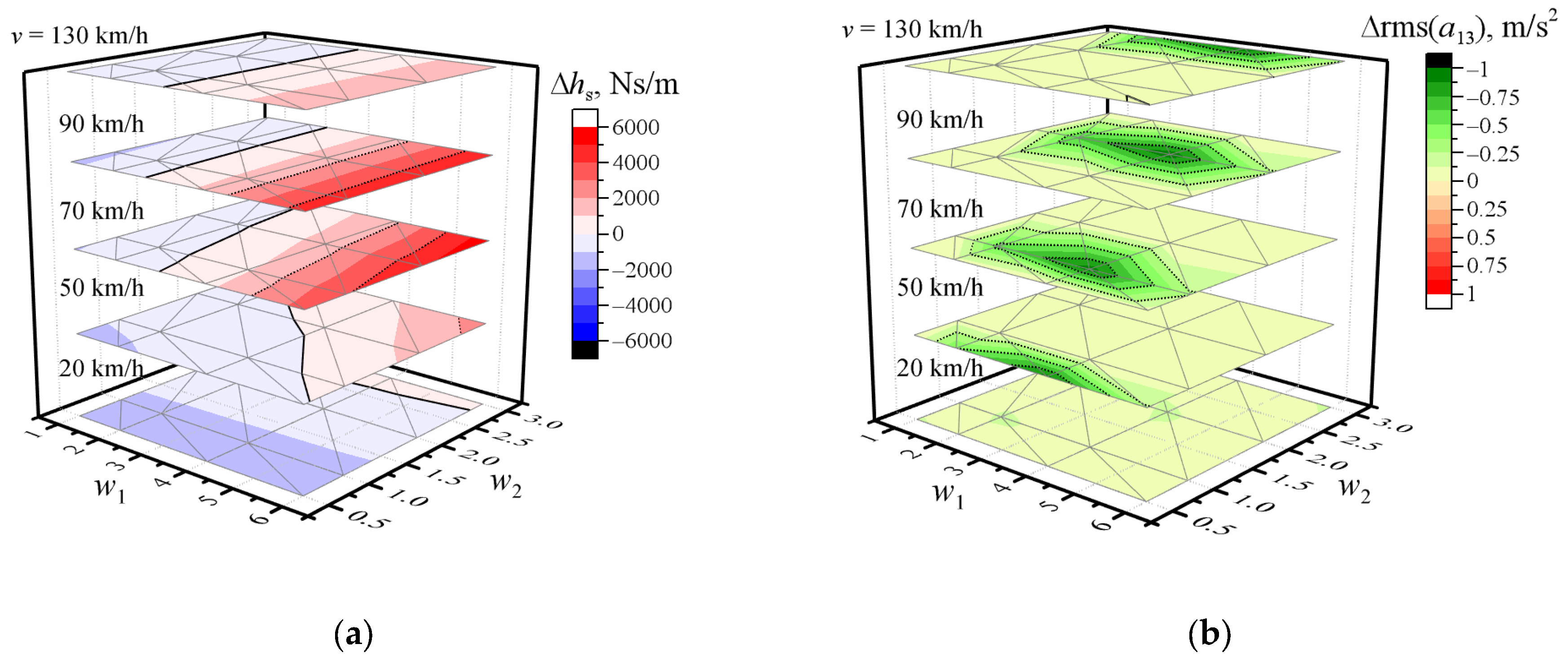
The results of all other cases are given as supplementary material Tables S1–S6 or are presented as the difference between optimized and non-optimized values in Figure 2a, Figure 3a, Figures S3a, S4a, S5a and S6a. As seen in the results, as the values of w1 and w2 increase, the values of optimal damping increase, except in situations of speed = 20 km/h and increasing w1. Analogic dependencies occur for all seven mass cases. This could be explained in two ways. First, using Equation (3), we have a small decrease in the G d ( Ω ) values in the range from 0.16 × 2π rad/m up to 0.21 × 2π rad/m increasing w1. Second, due to the relationships between angular spatial frequency Ω, frequency f, and velocity v  Ω = 2 π f v , we need higher angular spatial frequencies at decreasing speeds to excite the same minimal frequency. For example, to excite 1 Hz vibrations driving at 20 km/h, we need an angular spatial frequency of 0.18 × 2π rad/m. The highest damping values occur when w1 = 6 and speed varies from 70 km/h up to 90 km/h. Comparing the optimized damping with its value in a passive suspension system 2700 Ns/m [65], one can say that all values are smaller, except in several situations (m1 = m2 = 80 kg, w1 = 1, w2 = 3; m1 = 160 kg, w1 = 1, 2, 4, 6, w2 = 3; m1 = 100 kg, m2 = 60 kg, m3 = 50 kg, m4 = 40 kg, w1 = 1, 2, w2 = 3). The surface area of the bigger values increases with increasing car speed and reaches maximum damping values when the speed is 70 km/h or 90 km/h and w1 = 6. This was observed as well for other locations of masses (see Figure 2a, Figure 3a, Figures S3a, S4a, S5a and S6a). The highest damping is needed when mass m1 = 160 kg (from 1.1 up to 1.43 times bigger compared with m1 = 80 kg or 1.06–1.47 times compared with m1 = m2 = m3 = m4 = 80 kg). Comparing differences in the optimized damping of various locations of masses of 80 kg, the variations are less than 100 except in situations when w1 = 6 or v = 90 km/h. Graphic representation of the original and optimized values is presented in Figure 1b–d.
The dependencies of the optimized damping coefficient on vehicle speed (see Figures S1 and S2) show that:
  • When fixed waviness index = w1:
    • Higher damping values are needed, increasing values of w2 at low speed (differences amount to several hundreds);
    • This difference decreases with increasing speed (down to several tens);
    • Higher w1 values significantly increase damping values when the speed is more than 50 km/h;
    • It reaches the maximum when w1 = 6 and the speed is 70 km/h or 90 km/h.
  • When fixed waviness index = w2:
    • The differences of damping amount to several tens at 20 km/h speed;
    • This difference increases with increasing speed and reaches the maximum at 70 km/h or 90 km/h speed.
The dependence of RMS values of the optimized vertical acceleration of the driver, the difference between the RMS of the vertical accelerations of the driver when optimized and non-optimized, and the RMS of the non-optimized vertical accelerations of the driver on the road profile and speed when all masses are 80 kg are shown in Figure 1b–d, respectively. Other differences between the optimized and non-optimized RMS of the vertical accelerations of the driver are presented in Figure 2b and Figure 3b. One can observe the maximum RMS of the driver acceleration increasing as the speed shifts from lower w2 values to higher (see Figure 1b,d). We obtained all smaller driver acceleration values after optimization for all cases (Figure 1c, Figure 2b, Figure 3b, Figures S3b, S4b, S5b and S6b). For example, the change varies from 0 m/s2 up to 0.66 m/s2 when all masses are 80 kg, and up to 1 m/s2 when mass is 160 kg. This means that the acceleration of the driver could be reduced by up to 33% in comparison with non-optimized cases, depending on driving speed and road roughness. According to the ISO 2361 standard, the comfort level is very low when the total values of overall vibration magnitudes are from 1.25 m/s2 up to 2.5 m/s2 and becomes extremely uncomfortable when they are greater than 2.5 m/s2 [73]. When optimized acceleration is still high, we could recommend additionally a lower speed value. Thus, combining information about speed, masses and their locations from car sensors, optimal damping, RMS of vertical acceleration stored in a microcomputer or the cloud, and road information, we could control damping and recommend or reduce the driving speed [40,74].
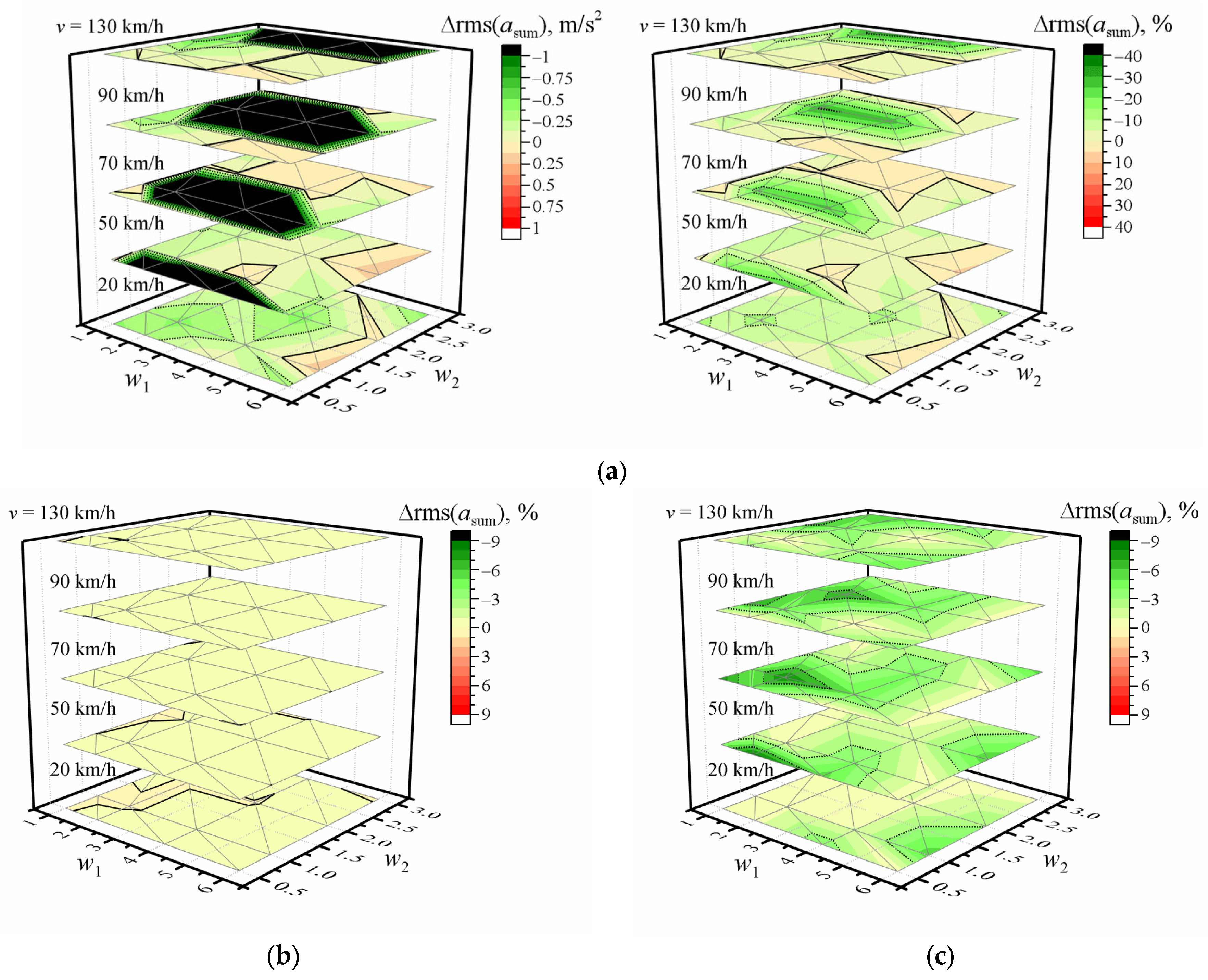
The calculated differences between the sums of the RMS of the vertical accelerations of the crew both when optimized for the driver and non-optimized, as presented in Figure 4a, show that it varies from 0.3 m/s2 down to −4.4 m/s2 (or in the range −35–6%). More detailed analysis showed that although driver acceleration was reduced, in a few situations the acceleration of the front-right passenger increased less than 0.1%. Meanwhile, the acceleration of the rear passengers decreased to 41% or increased to 31%. The biggest reduction of the rear passengers’ acceleration was observed when the sum of the acceleration decreased more than 10%. Moreover, the positive values of the differences between the sums of the RMS of the vertical accelerations are related to the bigger increase of the acceleration of the rear passengers. The question is, what is the most suitable to ensure the best driving comfort for all passengers and the driver. Usually, suspension systems have not one, but multiple different damping values in the front and rear of the vehicle.
The combined RMS vertical accelerations of the driver and rear-left passenger were chosen to optimize the suspension settings for ride comfort [75]. In addition, we optimized for the driver and front passenger or for the whole crew. The differences between the sum of the RMS of the vertical accelerations when optimized for the driver and front passenger or the whole crew, and when optimized for the driver, are presented in Figure 4b,c. The optimization for the driver only or for driver and front-right passenger give nearly the same results (the differences are less than 1%). In addition, it is true not only for the sum of the accelerations but also for the individual passenger’s acceleration. Consequently, both these optimizations could result in unacceptably high RMS vertical acceleration values for the rear passengers if left unchecked. Meanwhile, the sum of the RMS of the vertical accelerations is up to 9% smaller when optimizing for the whole crew than for only the driver. Simultaneously, the RMS of the vertical acceleration for the driver or front-right passenger increases up to 11% and 9%, respectively, and it decreases to 24% for rear passengers. Uys et al. [75] summarized the results of a simulation of an unmanned vehicle driving a measured road profile at 60 km/h: (1) when optimizing the RMS vertical acceleration of the driver, lower RMS vertical acceleration values for the driver are obtained; however, the RMS vertical acceleration of the rear-left passenger is 14% greater than that obtained by optimizing the combined driver and passenger RMS as an optimization objective; (2) when optimizing for combined RMS vertical acceleration, the lowest RMS vertical acceleration values for the passenger are obtained, but the driver RMS vertical acceleration is 13% higher than when optimizing for the driver only. One can state that these tendencies are true for all our cases when optimizing for the driver or the driver with a front passenger and when optimizing for the whole crew. So, further investigation will be required to discover how optimization is influenced if it will be used with different damping values for the front and rear wheels or for all wheels and various optimization objective functions.

4. Conclusions

The relationship between the detected road waviness values w1, w2 and the optimized damping coefficient under various locations of vehicle load positions could be used to control damping and recommend or reduce the driving speed. The needed optimized damping value could be interpreted from a 3D gridded matrix of damping coefficients calculated at certain fixed values of speed and waviness indexes w1, w2. The surface area of the bigger values increases in the case of increasing vehicle speed and reaches maximum damping values when the speed is 70 km/h or 90 km/h and w1 = 6. Up to 1.5 times higher damping values are required when only the driver mass is doubled than in other cases under study.
When optimizing the full-car model for the driver RMS vertical acceleration, the acceleration of the driver could be reduced up to 33% in comparison with non-optimized cases depending on driving speed and road roughness. The optimization for the driver and combined optimization for the driver and rear passenger provides results with differences less than 1%. Nevertheless, both these optimizations could result in unacceptably high values of rear-passenger RMS vertical acceleration if they are not set with a limitation. When optimizing for the whole crew, the sum of the RMS of the vertical accelerations is up to 9% smaller than when optimizing for the driver. Simultaneously, the RMS of vertical acceleration for the front passengers increases up to 10%, and it decreases to 24% for the rear passengers.
The output of this research provides a reason for the new design of damping devices, which can ensure higher comfort for the vehicle crew without changing the suspension design.

Supplementary Materials

The following supporting information can be downloaded at: https://www.mdpi.com/article/10.3390/app13095371/s1, Table S1. The optimized damping coefficients when the mass m1 = 80 kg; Table S2. The optimized damping coefficients when the masses m1 = m2 = 80 kg; Table S3. The optimized damping coefficients when the masses m1 = m3 = 80 kg; Table S4. The optimized damping coefficients when the masses m1 = m4 = 80 kg; Table S5. The optimized damping coefficients when the mass m1 = 160 kg; Table S6. The optimized damping coefficients when the masses m1 = 100 kg, m2 = 60 kg, m3 = 50 kg, m4 = 40 kg; Figure S1. Dependence of the optimized damping coefficient on vehicle speed when (a) w1 = 1; (b) w1 = 2; (c) w1 = 4; (d) w1 = 6, and all masses are m1 = m2 = m3 = m4 = 80 kg; Figure S2. Dependence of the optimized damping coefficient on vehicle speed when (a) w2 = 0.5; (b) w2 = 1; (c) w2 = 2; (d) w2 = 3, and all masses are m1 = m2 = m3 = m4 = 80 kg; Figure S3. Dependence of the difference between optimized and non-optimized (a) damping coefficient; (b) RMS of vertical accelerations of the driver; on-road profile waviness w1 and w2 when masses m1 = m2 = 80 kg and vehicle speed is 20 km/h, 50 km/h, 70 km/h, 90 km/h, or 130 km/h; Figure S4. Dependence of the difference between optimized and non-optimized (a) damping coefficient; (b) RMS of vertical accelerations of the driver; on-road profile waviness w1 and w2 when masses m1 = m3 = 80 kg and vehicle speed is 20 km/h, 50 km/h, 70 km/h, 90 km/h, or 130 km/h; Figure S5. Dependence of the difference between optimized and non-optimized (a) damping coefficient; (b) RMS of vertical accelerations of the driver; on-road profile waviness w1 and w2 when masses m1 = m4 = 80 kg and vehicle speed is 20 km/h, 50 km/h, 70 km/h, 90 km/h, or 130 km/h; Figure S6. Dependence of the difference between optimized and non-optimized (a) damping coefficient; (b) RMS of vertical accelerations of the driver; on-road profile waviness w1 and w2 when masses m1 = 100 kg, m2 = 60 kg, m3 = 50 kg, m4 = 40 kg and vehicle speed is 20 km/h, 50 km/h, 70 km/h, 90 km/h, or 130 km/h.

Author Contributions

Conceptualization, A.Č. and V.B.; methodology, A.Č. and N.Š.; software, N.Š., V.U. and I.I.; validation, A.Č., N.Š. and I.I.; formal analysis, A.Č. and I.I.; investigation, A.Č., N.Š. and I.I.; resources, N.Š., V.U. and I.I.; data curation, I.I.; writing—original draft preparation, A.Č.; writing—review and editing, A.Č. and V.B.; visualization, I.I.; supervision, V.B.; project administration, N.Š.; funding acquisition, V.B. All authors have read and agreed to the published version of the manuscript.

Funding

This research was funded by the European Commission within the European Union’s Horizon 2020 research innovation program funding ECSEL Joint Undertaking project AI4CSM under Grant Agreement No. 101007326.

Institutional Review Board Statement

Not applicable.

Informed Consent Statement

Not applicable.

Data Availability Statement

The data presented in this study are available on request from the corresponding author.

Conflicts of Interest

The authors declare no conflict of interest. The funders had no role in the design of the study; in the collection, analysis, or interpretation of data; in the writing of the manuscript; or in the decision to publish the results.

References

  1. Múčka, P.; Gagnon, L. Influence of tyre–road contact model on vehicle vibration response. Veh. Syst. Dyn. 2015, 53, 1227–1246. [Google Scholar] [CrossRef]
  2. Karnopp, D.; Crosby, M.J.; Harwood, R.A. Vibration Control Using Semi-Active Force Generators. J. Eng. Ind. 1974, 96, 619–626. [Google Scholar] [CrossRef]
  3. Sharp, R.S.; Crolla, D.A. Road Vehicle Suspension System Design—A review. Veh. Syst. Dyn. 1987, 16, 167–192. [Google Scholar] [CrossRef]
  4. Ma, X.; Wong, P.K.; Zhao, J. Practical multi-objective control for automotive semi-active suspension system with nonlinear hydraulic adjustable damper. Mech. Syst. Signal Process. 2019, 117, 667–688. [Google Scholar] [CrossRef]
  5. Savaresi, S.M.; Poussot-Vassal, C.; Spelta, C.; Sename, O.; Dugard, L. Chapter 2—Semi-Active Suspension Technologies and Models. In Semi-Active Suspension Control Design for Vehicles; Savaresi, S.M., Poussot-Vassal, C., Spelta, C., Sename, O., Dugard, L., Eds.; Butterworth-Heinemann: Boston, MA, USA, 2010; pp. 15–39. ISBN 978-0-08-096678-6. [Google Scholar]
  6. Soliman, A.; Kaldas, M. Semi-active suspension systems from research to mass-market—A review. J. Low Freq. Noise Vib. Act. Control 2021, 40, 1005–1023. [Google Scholar] [CrossRef]
  7. Ride Performance Innovation, Accelerated SM Electronic Damper Technologies. Available online: https://www.tenneco.com/assets/1/7/5498-Electronic_Damper_Technologies-9.8.pdf (accessed on 3 January 2023).
  8. Bedük, M.D.; Çalışkan, K.; Henze, R.; Küçükay, F. Advanced parameter analysis for damper influence on ride dynamics. J. Vib. Control 2018, 24, 1393–1411. [Google Scholar] [CrossRef]
  9. Mavroudakis, B.; Eberhard, P. Mode Decoupling Vehicle Suspension System Applied to a Race Car. In III European Conference on Computational Mechanics: Solids, Structures and Coupled Problems in Engineering: Book of Abstracts; Springer: Berlin/Heidelberg, Germany, 2006; p. 771. [Google Scholar] [CrossRef]
  10. Els, P.S.; Theron, N.J.; Uys, P.E.; Thoresson, M.J. The ride comfort vs. handling compromise for off-road vehicles. J. Terramechanics 2007, 44, 303–317. [Google Scholar] [CrossRef]
  11. Morales, A.L.; Nieto, A.J.; Chicharro, J.M.; Pintado, P. A semi-active vehicle suspension based on pneumatic springs and magnetorheological dampers. J. Vib. Control 2018, 24, 808–821. [Google Scholar] [CrossRef]
  12. Nieto, A.J.; Morales, A.L.; Chicharro, J.M.; Pintado, P. An adaptive pneumatic suspension system for improving ride comfort and handling. J. Vib. Control 2016, 22, 1492–1503. [Google Scholar] [CrossRef]
  13. Hać, A. Optimal Linear Preview Control of Active Vehicle Suspension. Veh. Syst. Dyn. 1992, 21, 167–195. [Google Scholar] [CrossRef]
  14. Barak, P. Passive Versus Active and Semi-Active Suspension from Theory to Application in North American Industry; SAE Technical Paper 922140; SAE International: Warrendale, PA, USA, 1992. [Google Scholar] [CrossRef]
  15. Ballo, I. Comparison of the properties of active and semiactive suspension. Veh. Syst. Dyn. 2007, 45, 1065–1073. [Google Scholar] [CrossRef]
  16. Lajqi, S.; Pehan, S. Designs and optimizations of active and semi-active non-linear suspension systems for a terrain vehicle. Stroj. Vestn. J. Mech. Eng. 2012, 58, 732–743. [Google Scholar] [CrossRef]
  17. Youn, I.; Hać, A. Semi-active suspensions with adaptive capability. J. Sound Vib. 1995, 180, 475–492. [Google Scholar] [CrossRef]
  18. Wu, T.H.; Lan, C.C. A wide-range variable stiffness mechanism for semi-active vibration systems. J. Sound Vib. 2016, 363, 18–32. [Google Scholar] [CrossRef]
  19. Tchamna, R.; Lee, M.; Youn, I. Attitude control of full vehicle using variable stiffness suspension control. Optim. Control Appl. Methods 2015, 36, 936–952. [Google Scholar] [CrossRef]
  20. Spelta, C.; Previdi, F.; Savaresi, S.M.; Bolzern, P.; Cutini, M.; Bisaglia, C.; Bertinotti, S.A. Performance analysis of semi-active suspensions with control of variable damping and stiffness. Veh. Syst. Dyn. 2011, 49, 237–256. [Google Scholar] [CrossRef]
  21. Jayachandran, R.; Krishnapillai, S. Modeling and optimization of passive and semi-active suspension systems for passenger cars to improve ride comfort and isolate engine vibration. J. Vib. Control 2013, 19, 1471–1479. [Google Scholar] [CrossRef]
  22. Huang, H.; Sun, S.; Chen, S.; Li, W. Numerical and experimental studies on a new variable stiffness and damping magnetorheological fluid damper. J. Intell. Mater. Syst. Struct. 2019, 30, 1639–1652. [Google Scholar] [CrossRef]
  23. Kumar, J.; Bhushan, G. Dynamic analysis of quarter car model with semi-active suspension based on combination of magneto-rheological materials. Int. J. Dyn. Control 2023, 11, 482–490. [Google Scholar] [CrossRef]
  24. Savaresi, S.; Poussot-Vassal, C.; Spelta, C.; Sename, O.; Dugard, L. Semi-Active Suspension Control Design for Vehicles; Butterworth-Heinemann: Boston, MA, USA, 2010; ISBN 9780080966786. [Google Scholar]
  25. Brezas, P.; Smith, M.C.; Hoult, W. A clipped-optimal control algorithm for semi-active vehicle suspensions: Theory and experimental evaluation. Automatica 2015, 53, 188–194. [Google Scholar] [CrossRef]
  26. Zhao, L.L.; Zhou, C.C.; Yu, Y.W. A research on optimal damping ratio control strategy for semi-active suspension system. Automot. Eng. 2018, 40, 41–47. [Google Scholar]
  27. Sayers, M.W.; Gillespie, T.D.; Queiroz, C.A.V. International Road Roughness Experiment: A Basis for Establishing a Standard Scale for Road Roughness Measurements; World Bank: Washington, DC, USA, 1986; ISBN 0821305891/9780821305898. [Google Scholar]
  28. Sayers, M.W.; Karamihas, S.M. The Little Book of Profiling-Basic Information about Measuring and Interpreting Road Profile; Regent of the University of Michigan: New York, NY, USA, 1998. [Google Scholar]
  29. Loprencipe, G.; Cantisani, G. Unified analysis of road pavement profiles for evaluation of surface characteristics. Mod. Appl. Sci. 2013, 7, 1–14. [Google Scholar] [CrossRef]
  30. Nguyen, T.; Lechner, B.; Wong, Y.D. Response-based methods to measure road surface irregularity: A state-of-the-art review. Eur. Transp. Res. Rev. 2019, 11, 43. [Google Scholar] [CrossRef]
  31. Tomizuka, M. “Optimum Linear Preview Control with Application to Vehicle Suspension”—Revisited. J. Dyn. Syst. Meas. Control 1976, 98, 309–315. [Google Scholar] [CrossRef]
  32. Louam, N.; Wilson, D.A.; Sharp, R.S. Optimal Control of a Vehicle Suspension Incorporating the Time Delay between Front and Rear Wheel Inputs. Veh. Syst. Dyn. 1988, 17, 317–336. [Google Scholar] [CrossRef]
  33. Louam, N.; Wilson, D.A.; Sharp, R.S. Optimization and Performance Enhancement of Active Suspensions for Automobiles under Preview of the Road. Veh. Syst. Dyn. 1992, 21, 39–63. [Google Scholar] [CrossRef]
  34. Hrovat, D. Optimal suspension performance for 2-D vehicle models. J. Sound Vib. 1991, 146, 93–110. [Google Scholar] [CrossRef]
  35. Soliman, A.M.A.; Crolla, D.A. Preview control for a semi-active suspension system. Int. J. Veh. Des. 1996, 17, 384–397. [Google Scholar]
  36. Sugasawa, F.; Kobayashi, H.; Kakimoto, T.; Shiraishi, Y.; Tateishi, Y. Electronically controlled shock absorber system used as a road sensor which utilizes super sonic waves. SAE Trans. 1985, 94, 15–25. [Google Scholar] [CrossRef]
  37. Rauh, J.; Ammon, D. System dynamics of electrified vehicles: Some facts, thoughts, and challenges. Veh. Syst. Dyn. 2011, 49, 1005–1020. [Google Scholar] [CrossRef]
  38. Tseng, H.E.; Hrovat, D. State of the art survey: Active and semi-active suspension control. Veh. Syst. Dyn. 2015, 53, 1034–1062. [Google Scholar] [CrossRef]
  39. Yang, Z.; Shi, C.; Zheng, Y.; Gu, S. A study on a vehicle semi-active suspension control system based on road elevation identification. PLoS ONE 2022, 17, e0269406. [Google Scholar] [CrossRef] [PubMed]
  40. Basargan, H.; Mihály, A.; Gáspár, P.; Sename, O. Cloud-based adaptive semi-active suspension control for improving driving comfort and road holding. IFAC Pap. 2022, 55, 89–94. [Google Scholar] [CrossRef]
  41. Pham, T.P.; Sename, O.; Tho Phan, C.; Bao Tran, G.Q. H∞ Observer for Road Profile Estimation in an Automotive Semi-active Suspension System Using Two Accelerometers. In Proceedings of 10th International Conference on Mechatronics and Control Engineering; Springer: Singapore, 2023; pp. 121–134. [Google Scholar] [CrossRef]
  42. Van Quynh, L.; Van Cuong, B.; Tan, H.A.; Huan, C.C. Modified Skyhook Control for Semi-active Electric Vehicle Suspension. In Proceedings of the Advances in Engineering Research and Application; Nguyen, D.C., Vu, N.P., Long, B.T., Puta, H., Sattler, K.-U., Eds.; Springer International Publishing: Cham, Switzerland, 2023; pp. 839–845. [Google Scholar]
  43. Jana, D.; Nagarajaiah, S. Data-driven full-field vibration response estimation from limited measurements in real-time using dictionary learning and compressive sensing. Eng. Struct. 2023, 275, 115280. [Google Scholar] [CrossRef]
  44. Lenkutis, T.; Viržonis, D.; Čerškus, A.; Dzedzickis, A.; Šešok, N.; Bučinskas, V. An Automotive Ferrofluidic Electromagnetic System for Energy Harvesting and Adaptive Damping. Sensors 2022, 22, 1195. [Google Scholar] [CrossRef]
  45. Lenkutis, T.; Čerškus, A.; Sitiajev, N.E.; Dumbrava, K.; Staugaitė, I.; Šešok, N.; Dzedzickis, A.; Bučinskas, V. Extraction of information from a PSD for the control of vehicle suspension. In Automation 2021: Recent Achievements in Automation, Robotics and Measurement Techniques; Springer International Publishing: Cham, Switzerland, 2021. [Google Scholar]
  46. Čerškus, A.; Lenkutis, T.; Šešok, N.; Dzedzickis, A.; Viržonis, D.; Bučinskas, V. Identification of road profile parameters from vehicle suspension dynamics for control of damping. Symmetry 2021, 13, 1149. [Google Scholar] [CrossRef]
  47. Turnip, A.; Hong, K.S. Road-frequency based optimisation of damping coefficients for semi-active suspension systems. Int. J. Veh. Des. 2013, 63, 84–101. [Google Scholar] [CrossRef]
  48. Lozia, Z. The use of a linear quarter-car model to optimize the damping in a passive automotive suspension system—A follow-on from many authors’ works of the recent 40 years. Arch. Motoryz. 2016, 71, 39–71. [Google Scholar] [CrossRef]
  49. Lozia, Z.; Zdanowicz, P. Optimization of damping in the passive automotive suspension system with using two quarter-car models. IOP Conf. Ser. Mater. Sci. Eng. 2016, 148, 012014. [Google Scholar] [CrossRef]
  50. Verros, G.; Natsiavas, S.; Papadimitriou, C. Design optimization of quarter-car models with passive and semi-active suspensions under random road excitation. JVC/J. Vib. Control 2005, 11, 581–606. [Google Scholar] [CrossRef]
  51. Marzbanrad, J.; Poozesh, P.; Damroodi, M. Improving vehicle ride comfort using an active and semi-active controller in a half-car model. JVC/J. Vib. Control 2013, 19, 1357–1377. [Google Scholar] [CrossRef]
  52. Bouazara, M.; Richard, M.J. An optimization method designed to improve 3-D vehicle comfort and road holding capability through the use of active and semi-active suspensions. Eur. J. Mech. A/Solids 2001, 20, 509–520. [Google Scholar] [CrossRef]
  53. Koulocheris, D.; Papaioannou, G.; Chrysos, E. A comparison of optimal semi-active suspension systems regarding vehicle ride comfort. IOP Conf. Ser. Mater. Sci. Eng. 2017, 252, 012022. [Google Scholar] [CrossRef]
  54. Makowski, M. Algorithm for Damping Control in Vehicle Suspension Equipped with Magneto-Rheological Dampers. In Springer Proceedings in Mathematics and Statistics; Springer: New York, NY, USA, 2018; Volume 248, pp. 235–247. ISBN 9783319965970. [Google Scholar]
  55. Yonglin, Z.; Jiafan, Z. Numerical simulation of stochastic road process using white noise filtration. Mech. Syst. Signal Process. 2006, 20, 363–372. [Google Scholar] [CrossRef]
  56. Shinozuka, M.; Jan, C.M. Digital simulation of random processes and its applications. J. Sound Vib. 1972, 25, 111–128. [Google Scholar] [CrossRef]
  57. Sun, L. Simulation of pavement roughness and IRI based on power spectral density. Math. Comput. Simul. 2002, 61, 77–88. [Google Scholar] [CrossRef]
  58. Ngwangwa, H.M.; Heyns, P.S.; Labuschagne, F.J.J.; Kululanga, G.K. Reconstruction of road defects and road roughness classification using vehicle responses with artificial neural networks simulation. J. Terramechanics 2010, 47, 97–111. [Google Scholar] [CrossRef]
  59. Agostinacchio, M.; Ciampa, D.; Olita, S. The vibrations induced by surface irregularities in road pavements—A Matlab® approach. Eur. Transp. Res. Rev. 2014, 6, 267–275. [Google Scholar] [CrossRef]
  60. Dharankar, C.S.; Hada, M.K.; Chandel, S. Numerical generation of road profile through spectral description for simulation of vehicle suspension. J. Braz. Soc. Mech. Sci. Eng. 2017, 39, 1957–1967. [Google Scholar] [CrossRef]
  61. Kansake, B.A.; Frimpong, S. Analytical modelling of dump truck tire dynamic response to haul road surface excitations. Int. J. Min. Reclam. Environ. 2020, 34, 1–18. [Google Scholar] [CrossRef]
  62. ISO 8608:2016. Mechanical Vibration—Road Surface Profiles—Reporting of Measured Data. ISO: London, UK, 2016. Available online: https://www.iso.org/obp/ui/#iso:std:iso:8608:ed-2:v1:en (accessed on 11 March 2021).
  63. Andrén, P. Power spectral density approximations of longitudinal road profiles. Int. J. Veh. Des. 2006, 40, 2–14. [Google Scholar] [CrossRef]
  64. Lenkutis, T.; Čerškus, A.; Šešok, N.; Dzedzickis, A.; Bučinskas, V. Road Surface Profile Synthesis: Assessment of Suitability for Simulation. Symmetry 2020, 13, 68. [Google Scholar] [CrossRef]
  65. Bucinskas, V.; Mitrouchev, P.; Sutinys, E.; Sesok, N.; Iljin, I.; Morkvenaite-Vilkonciene, I. Evaluation of Comfort Level and Harvested Energy in the Vehicle Using Controlled Damping. Energies 2017, 10, 1742. [Google Scholar] [CrossRef]
  66. Crolla, D.A. Vehicle Dynamics—Theory into Practice. Proc. Inst. Mech. Eng. Part D J. Automob. Eng. 1996, 210, 83–94. [Google Scholar] [CrossRef]
  67. Gobbi, M.; Levi, F.; Mastinu, G. Multi-objective stochastic optimisation of the suspension system of road vehicles. J. Sound Vib. 2006, 298, 1055–1072. [Google Scholar] [CrossRef]
  68. Ghafouri, J.; Sakhavati, A.; Jovari, R.; Gharehpetian, G.B. PI controller for quarter vehicle active suspension system with optimized gains using PSO algorithm. In Proceedings of the 2nd International Conference on Control, Instrumentation and Automation, Shiraz, Iran, 27–29 December 2011; pp. 379–383. [Google Scholar] [CrossRef]
  69. Els, P.S.; Uys, P.E.; Snyman, J.A.; Thoresson, M.J. Gradient-based approximation methods applied to the optimal design of vehicle suspension systems using computational models with severe inherent noise. Math. Comput. Model. 2006, 43, 787–801. [Google Scholar] [CrossRef]
  70. Els, P.S.; Uys, P.E. Investigation of the applicability of the dynamic-Q optimisation algorithm to vehicle suspension design. Math. Comput. Model. 2003, 37, 1029–1046. [Google Scholar] [CrossRef]
  71. Hrovat, D.; Hubbard, M. A comparison between jerk optimal and acceleration optimal vibration isolation. J. Sound Vib. 1987, 112, 201–210. [Google Scholar] [CrossRef]
  72. Taghipour, M.; Shahriari, D.; Shahsavari, A. Active Suspension Systems With Optimal Jerk Control. In Proceedings of the ASME 8th Biennial Conference on Engineering Systems Design and Analysis, Torino, Italy, 4–7 July 2006; pp. 359–364. [Google Scholar] [CrossRef]
  73. ISO 2631-1:1997. Mechanical Vibration and Shock—Evaluation of Human Exposure to Whole-Body Vibration—Part 1: General Requirements. ISO: London, UK, 1997. Available online: https://www.iso.org/obp/ui/#iso:std:iso:2631:-1:ed-2:v2:en (accessed on 17 January 2023).
  74. Wu, J.; Zhou, H.; Liu, Z.; Gu, M. Ride Comfort Optimization via Speed Planning and Preview Semi-Active Suspension Control for Autonomous Vehicles on Uneven Roads. IEEE Trans. Veh. Technol. 2020, 69, 8343–8355. [Google Scholar] [CrossRef]
  75. Uys, P.E.; Els, P.S.; Thoresson, M. Suspension settings for optimal ride comfort of off-road vehicles travelling on roads with different roughness and speeds. J. Terramechanics 2007, 44, 163–175. [Google Scholar] [CrossRef]
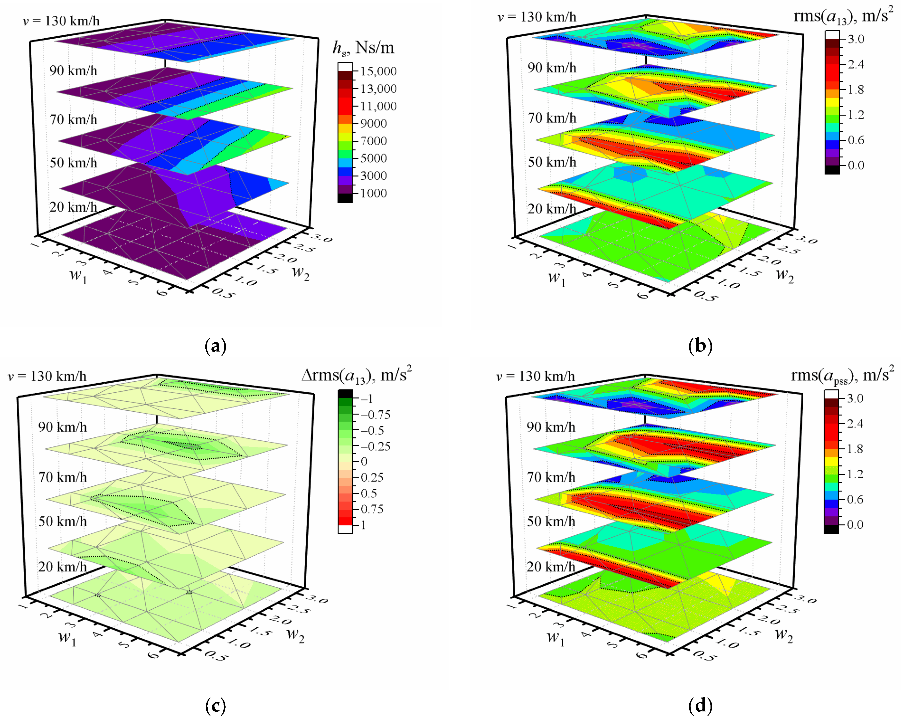
Figure 1. Dependence of (a) the optimized damping coefficient; (b) RMS of optimized vertical acceleration of the driver; (c) the difference between RMS of vertical accelerations of the driver when optimized and non-optimized; (d) RMS of non-optimized vertical acceleration of the driver; on-road profile waviness w1 and w2 when all masses are m1 = m2 = m3 = m4 = 80 kg and vehicle speed is 20 km/h, 50 km/h, 70 km/h, 90 km/h, or 130 km/h. Black dotted line shows values of major ticks. Black solid line is zero.
Applsci 13 05371 g001
Figure 2. Dependence of the difference between optimized and non-optimized (a) damping coefficient; (b) RMS of vertical accelerations of driver; on-road profile waviness w1 and w2 when m1 = 80 kg and vehicle speed is 20 km/h, 50 km/h, 70 km/h, 90 km/h, or 130 km/h. Black dotted line shows values of major ticks. Black solid line is zero.
Applsci 13 05371 g002
Figure 3. Dependence of the difference between optimized and non-optimized (a) damping coefficient and (b) RMS of vertical accelerations of the driver on-road profile waviness w1 and w2 when mass m1 = 160 kg and vehicle speed is 20 km/h, 50 km/h, 70 km/h, 90 km/h, or 130 km/h. Black dotted line shows values of major ticks. Black solid line is zero.
Applsci 13 05371 g003
Figure 4. Case of all masses m1 = m2 = m3 = m4 = 80 kg (a) difference between the sum of the RMS of the vertical accelerations when optimized for the driver and when non-optimized; (b) difference between the sum of the RMS of the vertical accelerations when optimized for the driver with front-right passenger and when optimized for the driver only; (c) difference between the sum of the RMS of the vertical accelerations when optimized for the whole crew and when optimized for the driver only. Black dotted line shows values of major ticks. Black solid line is zero.
Applsci 13 05371 g004
Table 1. Simulation of road profile impact to the vehicle body.
Road TypeCar ModelRemarksRefs.
Asphalt, concrete, roughQuarter-carModified skyhook control[47]
Sinusoidal and random roadFull-car (7DOF)LIDAR and diagonal recurrent neural network control model[23]
ISO class B, C, DQuarter-carOptimized damping using three criteria or modified criteria; various speeds[48,49]
Good and poor qualityQuarter-carOptimized damping and stiffness[50]
Random (max elevation 50 mm)Full-car (12DOF)Optimized damping and stiffness; separated engine[21]
Random (standard deviation 10 mm)Quarter-carGenetic algorithm[51]
Main road profile3D model with driverOptimized damping and stiffness for passive, semi-active, and active suspensions[52]
Bump 50 mmHalf-carC-K figures; genetic algorithm; various control methods[53]
Table 2. The optimized damping coefficients when all masses m1 = m2 = m3 = m4 = 80 kg.
hs, Ns/m
Waviness20 km/h50 km/h70 km/h90 km/h130 km/h
w1 = 1; w2 = 0.511311153114111061291
w1 = 2; w2 = 0.511291191141013781658
w1 = 4; w2 = 0.511221390243326872701
w1 = 6; w2 = 0.511161953472957394148
w1 = 1; w2 = 113261351128011701319
w1 = 2; w2 = 113191408159814781690
w1 = 4; w2 = 113121688273528812726
w1 = 6; w2 = 112992382526759444160
w1 = 1; w2 = 218561844158112951357
w1 = 2; w2 = 218391941197316631725
w1 = 4; w2 = 218082375332431972752
w1 = 6; w2 = 217763375629762724175
w1 = 1; w2 = 327472412185814021378
w1 = 2; w2 = 326892565231718111748
w1 = 4; w2 = 325963170386734222767
w1 = 6; w2 = 325124585728065084180
Disclaimer/Publisher’s Note: The statements, opinions and data contained in all publications are solely those of the individual author(s) and contributor(s) and not of MDPI and/or the editor(s). MDPI and/or the editor(s) disclaim responsibility for any injury to people or property resulting from any ideas, methods, instructions or products referred to in the content.