Article

Computation and Verification of Spatial Rate Equations for an Electro-Optically Q-Switched Laser-Diode Side-Pumped Nd:YAG Laser

National Key Laboratory of Science and Technology on Tunable Laser, Harbin Institute of Technology, Harbin 150001, China
*
Author to whom correspondence should be addressed.
Appl. Sci. 2023, 13(9), 5410; https://doi.org/10.3390/app13095410
Submission received: 30 March 2023 / Revised: 23 April 2023 / Accepted: 25 April 2023 / Published: 26 April 2023
(This article belongs to the Special Issue Advances in Optical and Optoelectronic Devices and Systems)

Abstract

:
In a side-pumped laser module, we simulate the pumping power distribution across the cross-section of Nd:YAG rods at varying diameters. The coupled rate equations with the spatial overlap efficiency for a four-level actively Q-switched side-pumped laser are considered complete. After a Q-switched pulse terminates, the expressions of laser output parameters are derived. We assess the single pulse energy, pulse width, and peak power using the analysis function. The 200 Hz Q-switched side-pumped Nd:YAG laser with a peak power of 103 kW and beam quality factors M2 = 1.67 is developed to the validity of theoretical models.

1. Introduction

The laser diode (LD) side-pumped is a standard pumping scheme for laser generation and amplification, particularly for lasers with moderate to high energy output. Side-pumping Q-switched lasers have been widespread in diverse applications, including laser-induced fluorescence and plasma, particle image velocimetry, and material research and processing [1,2,3,4,5,6,7,8]. Using PIV (particle image velocimetry) as an example, this technology collects real-time information about the flow field via laser [9,10,11]. Hence, the laser must have a high repetition and pulse energy to satisfy the detection requirements. The utilization of a Q-switch can enable the laser to consider the output requisites. Compared with passively Q-switched (PQS) ones, actively Q-switched (AQS) lasers have the advantages of faster switching, better hold-off ability, more considerable output energy, and controllable repetition rates [7,12,13]. Among various active Q-switching methods, electro-optical (EO) Q-switching is a competitive and practical option. However, EO Q-switched lasers typically require a high-voltage electronic or radio frequency transducer and have a thermal effect in the gain medium under conditions of high pumping power. To solve these issues, numerous research teams have conducted extensive research. One recent study has confirmed that some electro-optical crystals, such as Relaxor-lead titanate (PbTiO3), are tiny, and the driving voltage needed for the crystals can be decreased to a few hundred volts [14]. Hence, the volume of AQS lasers can be further compressed. In addition, periodic pulse pumping with short pumping durations and high pumping outputs can considerably mitigate the thermal effect in side-pumped lasers [9,10,11,12,13].
Mode matching in a laser refers to matching the resonator’s oscillated and pumping laser modes. If the two laser modes match well, a substantial power gain will be generated, and the output power of the laser will be increased [15,16,17,18,19]. The fundamental mode (TEM00), which approximates a Gaussian distribution, is the most robust mode of the resonator’s laser field distribution and has high beam quality. Excellent mode matching between TEM00 and pump beam in the resonator enables lasers with superior beam quality and excellent output power. Therefore, researching relationships of mode matches in laser designs is necessary. In addition, the rate equations represent a dynamic equation for laser output derived from altering population inversion at the atomic level within the gain medium, which can be utilized to derive the characteristic output curve of the laser. Specific research teams have successfully solved the rate equations to a greater extent to simulate and control the pulse waveform of the laser output [20,21,22]. For similar purposes, by incorporating the spatial overlap efficiency into the rate equations, the laser’s output performance can be more accurately simulated and calculated to reflect the resonator’s actual oscillation. Nevertheless, most contemporary models concerning coupled rate equations containing the overlap effect concentrate on end-pumped solid-state lasers [17,18,19,23]. The primary reason is that the direction of the pumping beam propagation is paralleled to the direction of the oscillating laser propagation in an end-pumped laser. Moreover, the fundamental transverse laser mode (TEM00) oscillates easily in an end-pump laser, making the spatial overlap effect easier to calculate. In Xie’s publication [24], although he computed the spatially linked rate equations for a side-pumped laser without Q-switch operation, he barely considered several parameters in the computation, such as the complex and variable intensity distribution of pumping power over the section of the gain medium. In addition, he assumed that only a fundamental transverse mode (TEM00) oscillated in the resonator, resulting in some discrepancies between the estimated and actual results. In Chen’s publication [23], the spatial rate equations for Q-switched lasers were solved but just for end-pumped lasers. In addition, his theoretical model applies solely to passive Q-switched end-pump lasers. Up to now, few types of research have been conducted on the rate equations with the spatial overlap efficiency for an electro-optically Q-switched side-pumping laser.
We conduct theoretical research and verified experiments on the electro-optical Q-switched side-pumping laser to solve the above problems and satisfy the demand for high-repetition advanced solid-state lasers in PIV and other applications. The theoretical research comprises the simulation of pumping power distribution, calculation of overlap efficiency in the resonator, and derivation of the spatial rate equation. After establishing the theoretical model, we build an electro-optical Q-switched side-pumping laser with a low modulated voltage and weak thermal effects to validate the theoretical calculation.
In further detail, we first simulate the pumping power distribution in a side-pumped laser module equipped with Nd:YAG rods of different sizes. Then, the spatial overlap efficiency in the resonator is calculated to estimate the matching relationship between the pumping beam and the laser mode oscillated in the resonator. By integrating the spatial overlap efficiency into the coupled rate equations, we are able to derive and subsequently solve the characteristic equation of the photon density for the Q-switched side-pumping laser. The analytic function we solve is exploited to analyze the output pulse energy, pulse width, and peak power with the pulse pumping power, respectively, while considering different Nd:YAG rod diameters. At last, we develop a 200 Hz Q-switched side-pumped Nd:YAG laser with a peak power of 103 kW and beam quality factors M2 = 1.67. Based on this laser, we conduct a series of experiments to validate the developed model and equations.

2. Pumping Intensity Distribution and Derivation of the Spatial Rate Equations

2.1. The Simulation of the Pumping Intensity Distribution in the Side-Pumped Laser Module

The structural diagram of the five-dimensional laser diode (LD) side-pumped module is depicted in Figure 1. In the module’s middle portion, the laser medium is enclosed by a transparent quartz flow tube. The deionized water serves as a cooling agent in the quartz flow tube, and the outer portion of the quartz flow tube is a highly reflecting material condenser [25,26]. Five LD arrays are outside the condenser to pump the 808 nm laser into the laser medium. The different structural components and geometric distances of the LD side-pumped module result in various distributions of the pumping power across the gain medium. Hence, the structural parameters of the commercial LD side-pumped module from Table 1 are considered during the simulation.
The research by Dr. Wu presents a method to simulate the pump power intensity distribution of the side pump module, which is based on the fundamental principle of the side-pumping laser module and the ray tracing algorithm [27]. However, the crystal rod in that study is in saturation-pumping absorption when the side-pumped module begins pumping. In other words, the pumping power distribution simulated in that research is actually intended for the side-pumped laser module as an amplifier rather than an oscillation. Our paper focuses on analyzing the matching efficiency between the side-pumped laser’s pumping beam and the resonator’s oscillating laser. Hence, the crystal rod in the unsaturation-pumping absorption is considered, and the pumping power distribution is stimulated when the side pump module is utilized as the laser oscillation.
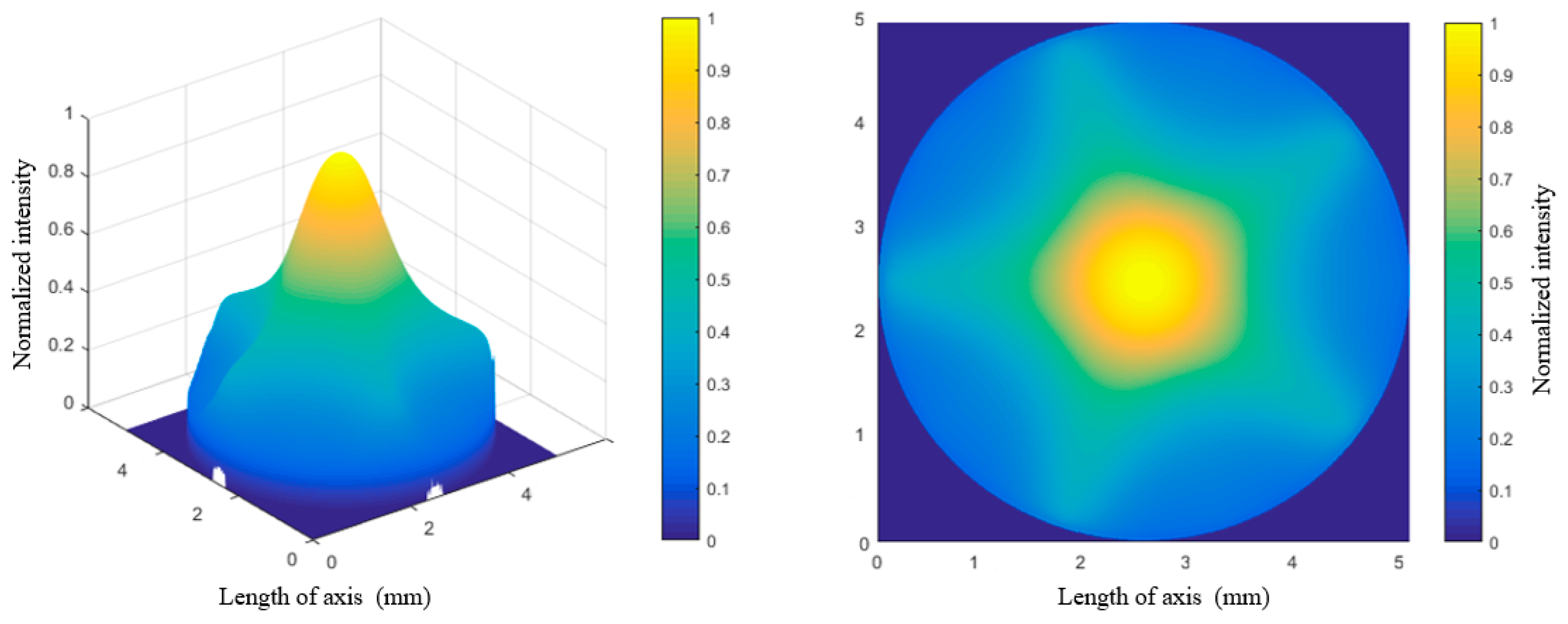
The improved algorithm is utilized to simulate the distribution of pumping power, and the simulation program is executed accordingly. The distribution of pumping power intensity across the 5 mm-diameter Nd:YAG rod in the side-pumped module is shown in Figure 2. The finite element mesh used in the simulation consists of 500 × 500 elements. For the convenience of presentation, the axes are converted to millimeter units. In addition, it is normalized and plotted to represent the cross-sectional area of a Nd:YAG rod for the follow-up comparison and computation. The simulated distribution of pumping power intensity across the five mm-diameter Nd:YAG rod findings suggest that the crystal rod’s pumping power distribution is non-uniform and non-Gaussian, with an irregular intensity profile.
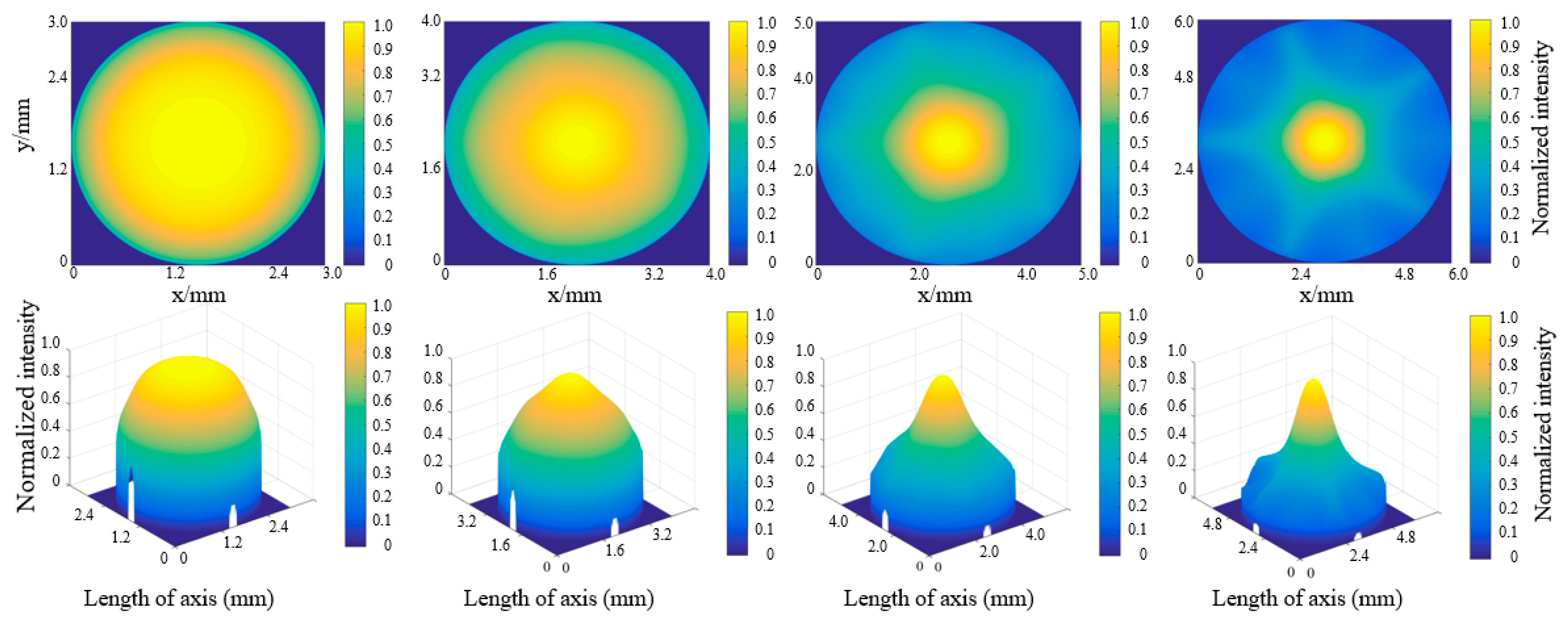
A series of simulated pumping power distributions across the crystal rod is obtained by varying the diameter of the Nd:YAG rod while keeping all other parameters constant. The alteration of the rod diameter results in a notable shift in the intensity distribution of the pumping power, as depicted in Figure 3. The intensity distribution is uniform when the diameter of the rod is small. When the rod’s diameter is large, the intensity distribution is uneven, with high intensity in the core and low power in the periphery. The intensity distribution even appears in a pentagram when the section diameter of the Nd:YAG rod is 5 mm or 6 mm, which can affect the spatial overlap efficiency and laser oscillated mode in the resonator [25,26,27]. We assume that the Gaussian distribution of pumping power is utilized to calculate the spatial overlap efficiency and subsequent calculations. Under such circumstances, the following calculated theoretical values will diverge significantly from the experimental values. Consequently, the subsequent analyses will fully account for our simulations of the pumping power distribution that are more representative of the actual situation.

2.2. Computation of Spatial Overlap Efficiency

The cross-sectional area of output laser Ae and spatial overlap efficiency S are provided by [16,17,23,24]. R(r, z) represents the spatial distribution of the pumping power throughout the gain rod. ϕ(r, z) is the intensity distribution across the section of the laser-oscillated mode in the resonator.
A e = [ R ( r , z ) ϕ ( r , z ) dxdy ] 1 ,
S = [ R ( r , z ) ϕ ( r , z ) dxdy ] 2 R ( r , z ) ϕ 2 ( r , z ) dxdy .
The previous section has already computed and simulated the distribution of the pumping power R(r, z). Therefore, the intensity distribution across the section of the oscillating laser mode needs to be determined utilizing Equations (3) and (4).
ϕ 1 ( r , z ) = 2 π ω l 2 ( z ) exp [ 2 r 2 ω l 2 ( z ) ] ,
ω l ( z ) = ω 0 1 + ( z λ / π ω 0 2 ) 2 ω 0 .
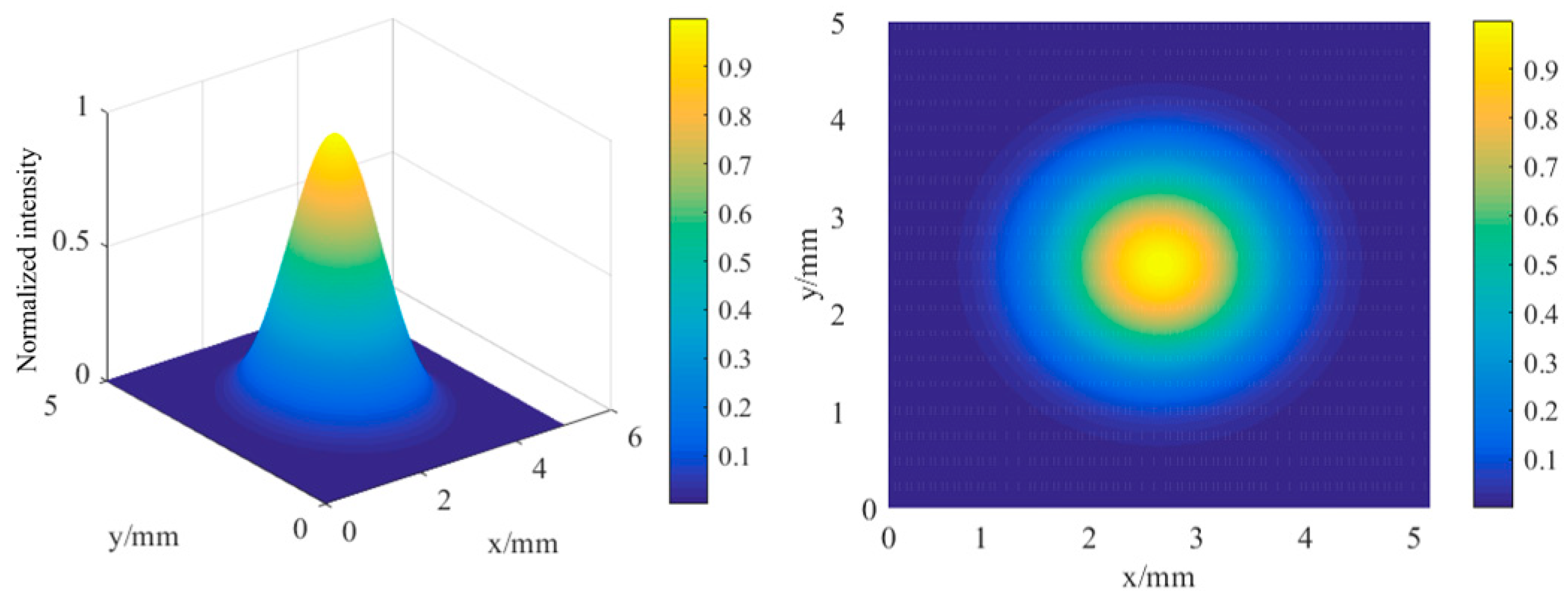
From Equations (3) and (4), the intensity distribution of the fundamental transverse mode is directly related to the beam waist size, which is determined by the parameters of the gain medium and the optical element positioned within the resonator. Thus, based on the primary parameters of the Q-switched Nd:YAG side-pump laser utilized in the experiment, the optical software can calculate the beam waist size of 2.09 mm. Figure 4 depicts the intensity distribution of the fundamental transverse mode ϕ1(r, z).
Because side-pumping lasers typically exhibit high-order mode oscillation, it is necessary to calculate the intensity distribution of the high-order laser mode. The expression for high-order mode can be represented by Equation (5), where J0 is the Bessel function of the first order. The actual oscillated laser mode ϕ(r, z) in a resonator of the side-pumped laser is the superposed intensity of the fundamental transverse mode ϕ1(r, z) and the higher-order mode ϕ2(r, z), as expressed by Equation (6).
ϕ 2 ( r , z ) = A 0 exp [ ( r ω 0 ( z ) ) n ] J 0 ( α r ) ,
ϕ ( r , z ) = ϕ 1 ( r , z ) + ϕ 2 ( r , z ) .
The intensity distribution after superposition is depicted in Figure 5. Compared to the distribution of the fundamental transverse mode ϕ1(r, z), the superposed intensity ϕ(r, z) shifts to a particular level. A Gaussian distribution still characterizes its central region, while its periphery has an explicit intensity distribution.
In previous calculations of spatial overlap efficiency, the distribution of pumping power in a side-pumped laser is approximated as a Gaussian distribution, and the high-order mode oscillation in a resonator is ignored. To guarantee the accuracy of computed results, our simulated outcomes that closely resemble the actual situation are wholly integrated into the subsequent calculation process, including the pumping power distribution R and oscillated laser mode ϕ.
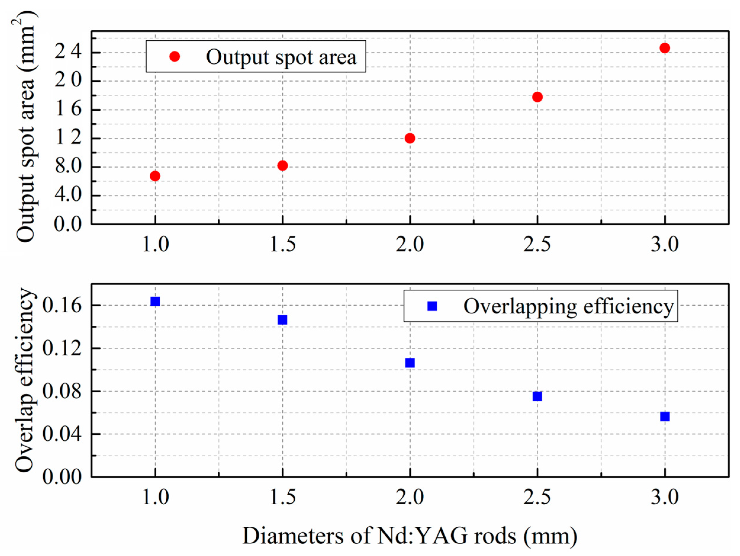
When R(r, z) and ϕ(r, z) are plugged into Equations (1) and (2), the spatial overlap efficiency S and the output laser cross-sectional area Ae can be computed by mathematical software. Figure 6 shows the computed results of the cross-sectional area of the output laser and spatial overlap efficiency in a Nd:YAG side-pumped laser with various rod diameters. As the diameter of the Nd:YAG rod increases, so does the cross-sectional area of the output laser Ae, but the spatial overlap efficiency S declines. Several of these computed results are applied to calculating the following spatial rate equations.

2.3. Solution of Spatially Coupled Rate Equations

The Q-switching process in the resonator is divided into two processes. When the pump source begins pumping (the Q-switch is off), laser oscillation cannot be generated, and the population inversions in the upper level of the gain medium can accumulate in large quantities. The time that energy can be stored is determined by the lifetime of the upper energy level of the laser medium. When the Q-switch turns on, the stimulated emission quickly intensifies. In a brief period, population inversions are consumed, converted into laser energy, and a laser pulse is emitted through the coupled mirror.
The gain medium utilized in the laser is the Nd:YAG crystal, which is a four-level atomic system. The four-level Q-switched rate equations are employed to depict the process of generating laser output pulses. The spatial rate equations for a four-level AQS operation are provided by
d N d t = B Φ N ,
d Φ d t = [ B A e l N 1 τ c ] Φ ,
where N is the population inversion density in the gain medium. Φ is the photon density in the resonator, t is time, and B is the stimulated emission probability of each photon in each laser mode. L is the length of the medium gain rod, τ c is the photon’s lifetime in the resonator, and Ae is the previously mentioned cross-sectional area of the output laser beam.
When d Φ / d t = 0 corresponding to the output laser pulse peak of the PQS laser, Equation (9) can be used to determine the population inversion density at the peak of the output laser pulse Np.
N p = γ / σ l ,
where γ is the loss factor of the resonator when the Q switch is on, σ is the stimulated emission cross-section of the gain medium. l is the length of the gain medium. In the situation where d Φ / d t = 0 , it can be observed that the round-trip loss is equivalent to the gain in the resonator. This condition is also consistent with the laser’s threshold operation. Hence, the equation Np = Nic holds, where Nic is the initial threshold inversion population density during the laser’s normal operational state (the Q switch is on).
Furthermore, it was noticed that the Nic is directly proportional to the threshold pump power denoted by Ppc. Similarly, the initial inversion population density Ni is proportional to the average pump power of Pp during the regular laser operation. Therefore, the proportional formula N ic / N i = P pc / P p can be obtained. According to Equation (9), the initial inversion population density Ni can be represented further as follows:
N i = N p P p P pc = γ σ l P p P pc .
The values of loss factor γ , stimulated emission cross-section σ , length of the gain medium rod l, and the threshold pump power Ppc are known for our laser. Thus, the functional relationship between the initial inversion population Ni and the average pump power Pp is available.
By integrating the ratio of Equations (7) and (8) and substituting the boundary conditions, the final inversion population Nf can be expressed as
N i N f N i = N p N i ln N i N f .
It can be noted that once the values of NP and Ni are determined, the values of Nf can be solved according to Equation (11).
In previous models [25,28], the output pulse energy Eout, peak power Pout, and pulse width Δ τ p are provided by
E out = S A e h υ 2 σ γ N i N f ,
P out = γ 2 S A e h υ 2 σ τ c N i N p ln ( N i N p ) 1 ,
Δ τ p = τ c ( N i N f / N p ) [ ( N i / N p ) ln ( N i / N p ) 1 ] .
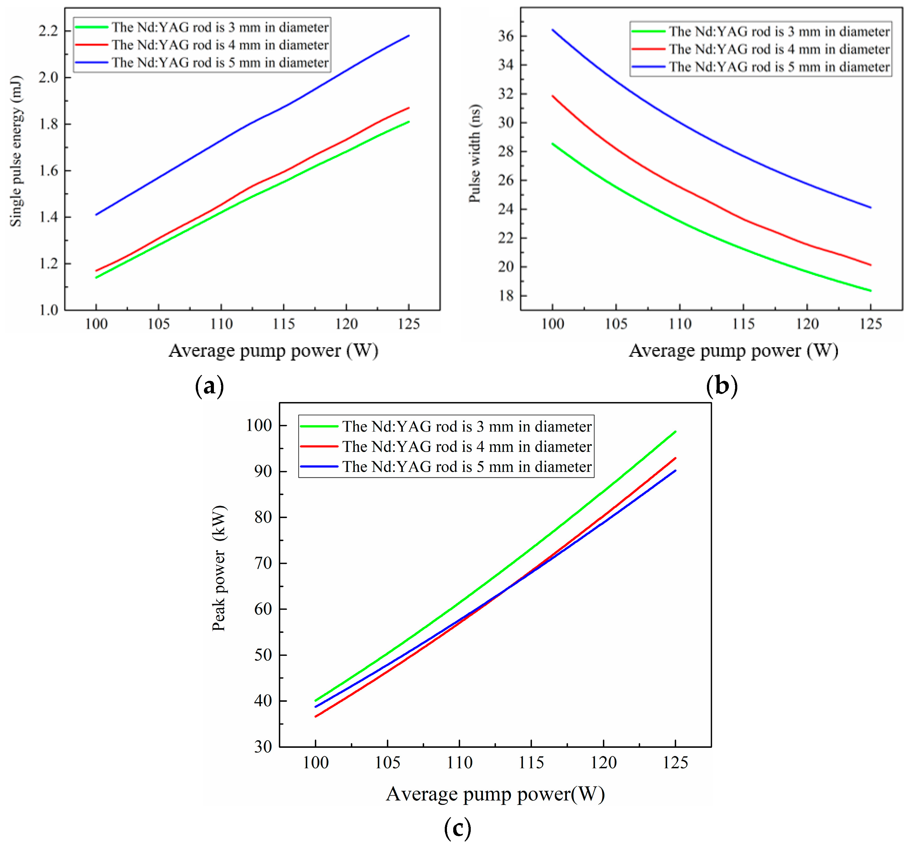
The side-pumped laser’s gain medium is Nd:YAG rod, with the stimulated emission cross section σ = 2.8 × 10⁻²³ m2 (1064 nm) and photon energy h υ = 1.87 × 10⁻¹⁹ J (1064 nm). The effective cavity length is approximately Le = 350 mm, and the Nd:YAG rod length is l = 105 mm. The transmittance of the output coupling mirror is T = 30%, and the output coupling mirror loss γ 2 = ln ( 1 T 2 ) = 0.35. The loss factor of the resonator is γ = 0.1 + γ 2 / 2 = 0.28 when the Q switch is on. In addition, the spatial overlap efficiency and output spot area at varying Nd:YAG rod diameters have previously been computed. Consequently, the functional relationship between single pulse energy, pulse width, peak power, and average pump power (808 nm laser) is shown in Figure 7 by plugging the values of the related parameter.
The linear relationship between the single pulse energy of the Q-switched pulse and the average pump power is observed. The pulse width is approximately inversely proportional to the average pump power. Peak power initially increases logarithmically and then approaches a linear relationship with the average pump power. As the diameter of the Nd:YAG rod increases, the threshold pump power of the laser drops, and the slope of the single pulse energy increase as the pump power rises. Despite this, installing the large Nd: YAG rod in the side-pumped laser reduces the peak power and widens the pulse width of the output laser. The observed phenomenon can be attributed to the non-uniform distribution of pumping power intensity and the consequent reduction in spatial overlap efficiency. Detailed experiments will be conducted to verify the accuracy of the computed results.

3. Experimental Setup

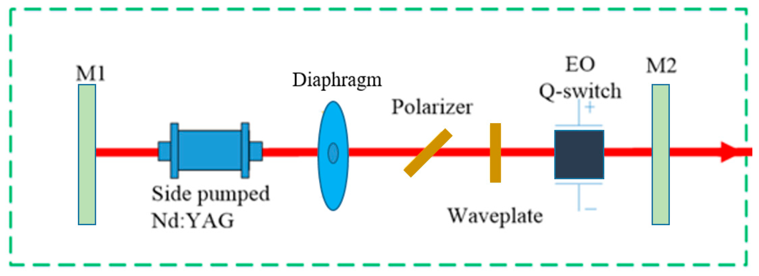
The schematic diagram of a Q-switched LD side-pumped Nd:YAG laser operating at a repetition of 200 Hz is presented in Figure 8. The LD side-pumped module has the ability to achieve a peak pump power of 2000 W when operating at a repetition rate of 200 Hz while exhibiting minimal thermal effect. To restrict the high-order laser modes and promote the efficient oscillation of the fundamental laser mode (TEM00), a 2.15 mm aperture diaphragm was introduced into a resonator with a length of 280 mm. The polarization state of the resonator was adjusted through the combined utilization of a polarizer and a wave plate [29]. Mirror M1 was coated with a highly reflective material at a wavelength of 1064 nm, while mirror M2 had a transmissivity of 30% at the same wavelength. Sequential assembly of Nd:YAG rods with cross-sectional diameters of 3 mm, 4 mm, and 5 mm was performed to construct a side-pumped module for validating experiments.

4. Experimental Results and Verification of Spatially Coupled Rate Equations

To evaluate the validity of the developed model, an electro-optic (EO) Q-switched laser was constructed employing a five-dimensional LD side-pumped Nd:YAG module with the same structural parameters as the side-pumped module used in the simulation experiments. A pulse pumping scheme with a duty ratio of 12.5% was implemented to reduce the thermal effect in the Nd:YAG rod [30]. Under an EO Q-switched operation with a frequency of 200 Hz, the output laser characteristics of our side-pumped laser with various Nd:YAG rod diameters were determined.
Figure 9 depicts the relationship between the single pulse energy, pulse width, peak power, and average pump power for various Nd:YAG rod diameters. When the side-pumped module was assembled with 3 mm Nd:YAG crystal rods, a maximum pulse width of 18 ns and a maximum peak power of 103 kW were obtained. The maximum single-pulse energy of 2.3 mJ was obtained using a 5 mm Nd:YAG crystal rod. Experimental results demonstrated that when the side-pumped module was assembled with a crystal rod of a small diameter, the spatial overlap efficiency was higher, and the pulse width was narrower. However, utilizing a crystal rod with a large diameter significantly decreased the peak power and expanded the pulse width. The observed phenomenon was ascribed to the non-uniform distribution of pumping power intensity over the cross-sectional area of the Nd:YAG rod with a large diameter. As a result, the oscillation of high-order modes was aggravated in the resonator, which diminished the overlap efficiency and affected the output pulse width [31].
In general, the experimental values obtained by employing 3 mm and 4 mm Nd:YAG rods corresponded well with the fitting function curve. Under the same conditions, the theoretical values are within the experimental values’ 5% error bar range. There were some deviations between the experimental values and the simulated curve upon employing a crystal rod of 5 mm. Due to using a crystal rod with a large diameter, higher-order modes oscillated in the resonator than expected, resulting in deviations between the experimental and theoretical values.
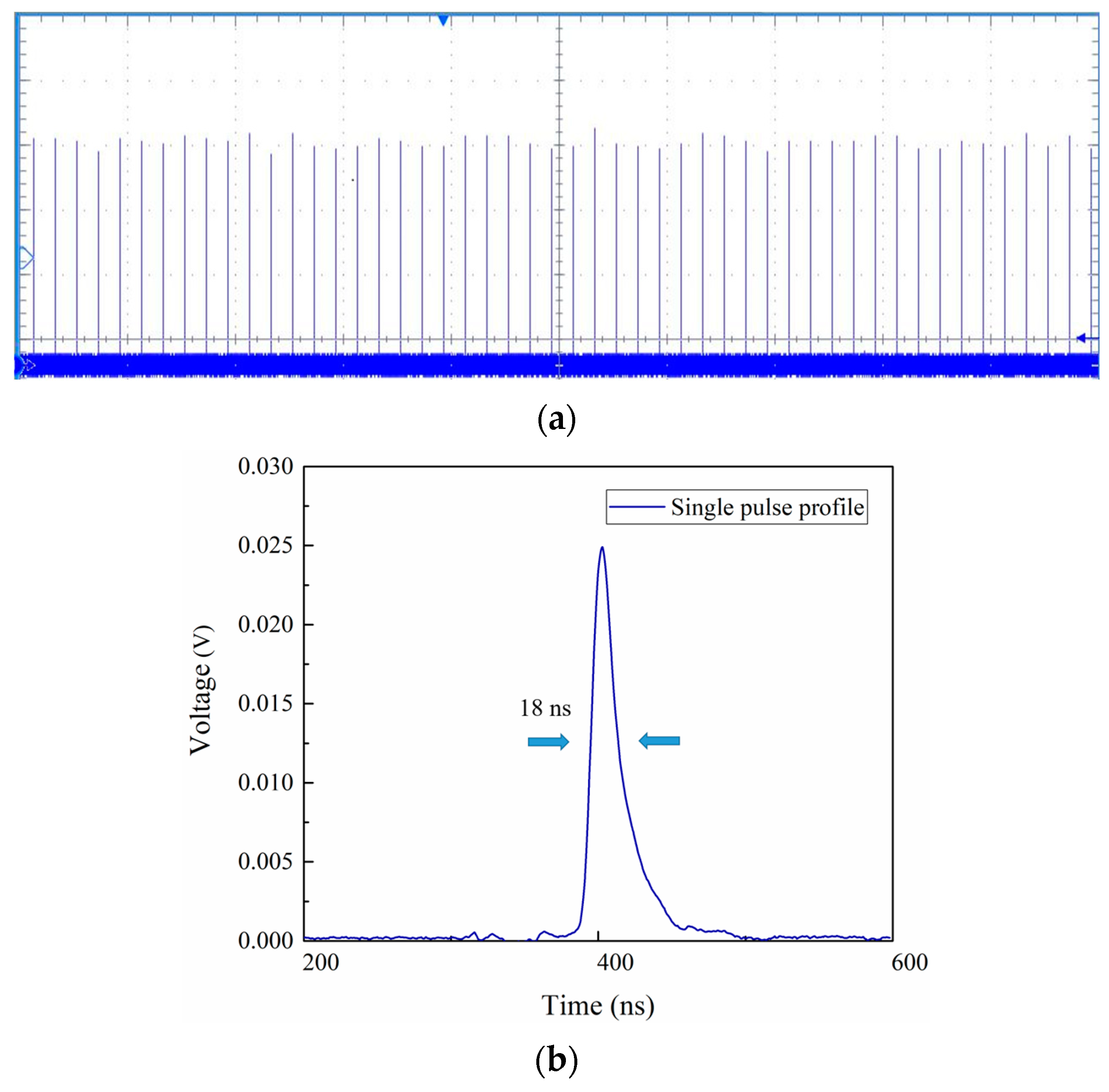
A high-speed silicon photo-detector was utilized to detect the output laser pulse, which had a maximum peak power of 103 kW. The detected pulse was subsequently displayed on a digitizing oscillograph. The uniform pulse width of a 200 Hz pulse train was demonstrated in Figure 10, with a pulse width of 18 ns. The M2 factors were also measured using a traveling 90/10 knife-edge method when the laser was at maximum peak power. Figure 11 shows that the output laser beam possessed a uniform cross-sectional intensity distribution and excellent beam quality.
In conclusion, the spatially coupled rate equations were proven to be valid by our Q-switched side-pumped Nd:YAG laser experiment. The laser developed in this paper will be used as the main oscillation stage and cooperate with the subsequent amplification stage to form a complete laser system. The laser system will then undergo ambient temperature and vibration testing to fully meet the reliability requirements of laser applications such as PIV.

5. Conclusions

The present study involved the simulation of the intensity distribution of pumping power in the LD side-pumped laser module with a focus on examining the effect of varying Nd:YAG rod diameters. The analytical model for a four-level electro-optic side-pumped laser was developed by taking into account the spatial overlap efficiency according to the rate equations. After the Q-switched pulse ended, the single pulse energy, pulse width, and peak power were analyzed using the fitting function. The Nd:YAG laser was developed for the purpose of validating the accuracy of a model, which had a peak power of 103 kW and a beam quality factor of M2 = 1.67.

Author Contributions

Conceptualization, R.Y.; Methodology, H.X.; Software, X.L.; Investigation, R.Y.; Resources, X.L.; Writing–original draft, H.X.; Writing–review & editing, R.Y.; Supervision, X.L. All authors have read and agreed to the published version of the manuscript.

Funding

This work was supported by the Natural Science Foundation of Heilongjiang Province, China (Grant No. LH2020F048) and Jiangsu Provincial Natural Science Foundation of China under Grant BK20201187. This work was financially supported by Yugang Jiang, Long Zhou and Yijun Jiang.

Institutional Review Board Statement

Not applicable.

Informed Consent Statement

Informed consent was obtained from all subjects involved in the study.

Data Availability Statement

You can contact the corresponding author for the data on this article.

Conflicts of Interest

The authors declare no conflict of interest.

References

  1. Johchi, A.; Naka, Y.; Shimura, M. Investigation on rapid consumption of fine-scale unburned mixture islands in turbulent flame via 10 kHz simultaneous CH-OH PLIF and SPIV. Proc. Combust. Inst. 2015, 35, 3663–3671. [Google Scholar] [CrossRef]
  2. Hedman, T.D.; Cho, K.Y. High speed OH PLIF applied to multiphase combustion. Combust. Explos. Shock Waves 2016, 52, 1–13. [Google Scholar] [CrossRef]
  3. Bai, Z.; Zhao, Z. A comprehensive review on the development and applications of narrow-linewidth lasers. Microw. Opt. Technol. Lett. 2021, 64, 2244–2255. [Google Scholar] [CrossRef]
  4. Slipchenko, M.N.; Meyer, T.R.; Roy, S. Advances in burst-mode laser diagnostics for reacting and nonreacting flows. Proc. Combust. Inst. 2021, 38, 1533–1560. [Google Scholar] [CrossRef]
  5. Seitzman, J.M.; Hanson, R.K. Planar Fluorescence Imaging: Basic Concepts for Scalar and Velocity Measurements. In Combustings Flow Diagnostics; Durão, D.F.G., Heitor, M.V., Whitelaw, J.H., Witze, P.O., Eds.; Springer: Berlin/Heidelberg, Germany, 1992; pp. 137–157. [Google Scholar]
  6. Roy, S.; Miller, J.D.; Slipchenko, M.N. 100-ps-pulse-duration, 100-J burst-mode laser for kHz–MHz flow diagnostics. Opt. Lett. 2014, 39, 6462–6465. [Google Scholar] [CrossRef]
  7. Wu, W.; Li, X. Continuous-wave and pulsed 1,066-nm Nd:Gd0.69Y0.3TaO4 laser directly pumped by a 879-nm laser diode. Opt. Express 2018, 26, 15705–15717. [Google Scholar] [CrossRef] [PubMed]
  8. Zhang, Y. Influence of the Surface Modification on Carrier Kinetics and ASE of Evaporated Perovskite Film. IEEE Photonics Technol. Lett. 2023, 35, 285–288. [Google Scholar] [CrossRef]
  9. Smyser, M.E.; Rahman, K.A. Compact burst-mode Nd:YAG laser for kHz–MHz bandwidth velocity and species measurements. Opt. Lett. 2018, 43, 735–738. [Google Scholar] [CrossRef]
  10. Fisher, J.M.; Smyser, M.E. Burst-mode femtosecond laser electronic excitation tagging for kHz–MHz seedless velocimetry. Opt. Lett. 2020, 45, 335–338. [Google Scholar] [CrossRef]
  11. Roy, S.; Jiang, N. Development of a three-legged, high-speed, burst-mode laser system for simultaneous measurements of velocity and scalars in reacting flows. Opt. Lett. 2018, 43, 2704–2707. [Google Scholar] [CrossRef]
  12. Liu, Y.; Yan, R. High-repetition-rate passively Q-switched Nd:GdTaO4 1066 nm laser under 879 nm pumping. Infrared Phys. Technol. 2019, 102, 103025. [Google Scholar] [CrossRef]
  13. Li, X.; Xu, H.; Yan, R. Comparison on performances of continuous-wave and acousto-optically Q-switched Nd:GdYTaO4 lasers under 808 nm and 879 nm pumping. Infrared Phys. Technol. 2020, 110, 103449. [Google Scholar] [CrossRef]
  14. Liu, X.; Tan, P.; Wang, D.; Jin, X.; Liu, Y.; Xu, B.; Qiao, L.; Qiu, C.; Wang, B.; Wei, C.; et al. Ferroelectric crystals with giant electro-optic property enabling ultracompact Q-switches. Science 2022, 376, 371–377. [Google Scholar] [CrossRef]
  15. Catela, M.; Liang, D. Renovating electrical power-to-TEM00 mode laser power conversion efficiency with four-lamp/fourrod pumping scheme. J. Mod. Optic 2021, 68, 895–905. [Google Scholar] [CrossRef]
  16. Chen, Y.; Huang, T. Optimization in scaling fiber-coupled laser-diode end-pumped lasers to higher power: Influence of thermal effect. IEEE J. Quantum Elect. 1997, 33, 1424–1429. [Google Scholar] [CrossRef]
  17. Peng, X.; Lei, X. Power scaling of diode-pumped Nd:YVO4 lasers. IEEE J. Quantum Elect. 2002, 38, 1291–1299. [Google Scholar] [CrossRef]
  18. Almeida, J.; Liang, D. Design of TEM00 mode side-pumped Nd:YAG solar laser. Opt. Commun. 2014, 333, 219–225. [Google Scholar] [CrossRef]
  19. Sun, Z.; Li, R. Experimental study of high-power pulse side-pumped Nd:YAG laser. Opt. Laser Technol. 2005, 37, 163–166. [Google Scholar] [CrossRef]
  20. Boutabba, N.; Grira, S. Analysis of a q-deformed hyperbolic short laser pulse in a multi-level atomic system. Sci. Rep. 2022, 12, 9308. [Google Scholar] [CrossRef]
  21. Grira, S.; Boutabba, N. Exact Solutions of the Bloch Equations of a Two-Level Atom Driven by the Generalized Double Exponential Quotient Pulses with Dephasing. Mathematics 2022, 10, 2105. [Google Scholar] [CrossRef]
  22. Boutabba, N.; Grira, S. Atomic population inversion and absorption dispersion-spectra driven by modified double-exponential quotient pulses in a three-level atom. Results Phys. 2021, 24, 104108. [Google Scholar] [CrossRef]
  23. Xie, W.; Tam, S.C.; Lam, Y.L. Influence of the thermal effect on the TEM00 mode output power of a laser-diode side-pumped solid-state laser. Appl. Optics 2000, 39, 5482. [Google Scholar] [CrossRef]
  24. Chen, Y.; Hsieh, M.; Tu, Y. Pedagogically fast model to evaluate and optimize passively Q-switched Nd-doped solid-state lasers Optics letters. Opt. Lett. 2021, 46, 1588–1591. [Google Scholar] [CrossRef]
  25. Sundar, R.; Hedaoo, P. Modular pump geometry for diode side-pumped high-power Nd:YAG rod laser. Appl. Optics 2015, 33, 9855. [Google Scholar] [CrossRef]
  26. Sundar, R.; Ranganathan, K. Modular pump head design of diffused, metal, and hybrid pump geometry for diode-side-pumped high power Nd:YAG laser. Appl. Optics 2016, 27, 7530. [Google Scholar] [CrossRef]
  27. Wu, W.; Li, X. Low heat-effect side-pumping gain module with evenly Gaussian to flat-top fluorescence distribution. Opt. Laser Technol. 2020, 127, 106203. [Google Scholar] [CrossRef]
  28. Orazio, S. Principles of Lasers, 5th ed.; Springer: New York, NY, USA, 2010; pp. 330–332. [Google Scholar]
  29. Zhou, Y.; Li, X. 500 Hz, 47.1 mJ, sub-nanosecond MOPA laser system. Opt. Laser Technol. 2021, 134, 106592. [Google Scholar] [CrossRef]
  30. Wu, W.; Li, X. Cavity-dumped burst-mode Nd:YAG laser master-oscillator power-amplifier system with a flat-top beam output realized by gain profile-controlled side pumping. Opt. Express 2022, 30, 20401–20414. [Google Scholar] [CrossRef]
  31. Li, C.; Lu, C. 2.36 J, 50 Hz nanosecond pulses from a diode side-pumped Nd:YAG MOPA system. Opt. Commun. 2017, 394, 1–5. [Google Scholar] [CrossRef]
Figure 1. The cross-section structure diagram of 5-dimensional laser diode (LD) side-pumped modules.
Applsci 13 05410 g001
Figure 2. Simulation of the pumping power distribution across the section of the Nd:YAG with a 5 mm side-pump module rod diameter.
Applsci 13 05410 g002
Figure 3. The LD side-pumped module’s intensity distribution of pumping power at various Nd:YAG rod diameters. The rod section diameter is 3 mm, 4 mm, 5 mm and 6 mm, respectively.
Applsci 13 05410 g003
Figure 4. The intensity distribution of fundamental transverse mode in the resonator.
Applsci 13 05410 g004
Figure 5. The intensity distribution of oscillated mode in the resonator of the side-pumped laser.
Applsci 13 05410 g005
Figure 6. The spatial overlap efficiency S and the cross-sectional area of output laser Ae with the different Nd:YAG rod diameters.
Applsci 13 05410 g006
Figure 7. Computed output laser performance based on spatial rate equations versus average optical pumping power for various Nd:YAG rod diameters. (a) Single pulse energy versus average pump power; (b) pulse width versus average pump power; (c) peak power versus average pump power.
Applsci 13 05410 g007
Figure 8. The diagram illustrates a side-pumped Nd:YAG laser.
Applsci 13 05410 g008
Figure 9. Comparison between experimental and theoretical results for output laser characteristics at different Nd:YAG rod diameters. (a) Single pulse energy versus average pump power; (b) pulse width versus average pump power; (c) peak power versus average pump power.
Applsci 13 05410 g009
Figure 10. Pulse train and pulse width of the Q-switched Nd: YAG side-pumped laser. (a) 200 Hz Laser pulse train; (b) single pulse profile.
Applsci 13 05410 g010
Figure 11. The beam cross-sectional intensity distribution profile of the output laser and beam quality factors (M2) at the maximum peak power of 103 kW. (a) Intensity distribution profile. (b) Beam quality factors.
Applsci 13 05410 g011
Table 1. Characteristics of commercial side-pumping modules.
ParametersNumerical Values
Number of pumping directions5
Distance between LD bars and gain medium center6.1 mm
Manufacturer of LD bars Coherent Inc.
LD bar model100 W 50 FF × 2 mm TE
Fast axis divergence of LD bars (1/e2)~50°
The refractive index of the gain medium1.82
The refractive index of the cooling liquid1.33
The refractive index of the flow tube1.45
The inner diameter of the flow tube5.9 mm
The wall thickness of the flow tube1.67 mm
Effective pumping length~50 mm
Rated centroid pumping wavelength 808 nm
Laser mediumNd:YAG
The doping concentration of the laser medium0.6 at.%
Diameter of the medium gain rod3 mm, 4 mm, 5 mm, 6 mm
Gain medium-side surface diffusion (divergence)~15°
Disclaimer/Publisher’s Note: The statements, opinions and data contained in all publications are solely those of the individual author(s) and contributor(s) and not of MDPI and/or the editor(s). MDPI and/or the editor(s) disclaim responsibility for any injury to people or property resulting from any ideas, methods, instructions or products referred to in the content.