Fatigue Resistance of Fillet Welds of Traction Rod Brackets on a Locomotive Bogie Based on International Union of Railways Standards and Improvement Measures Adopted

Abstract
:1. Introduction
2. Methodology
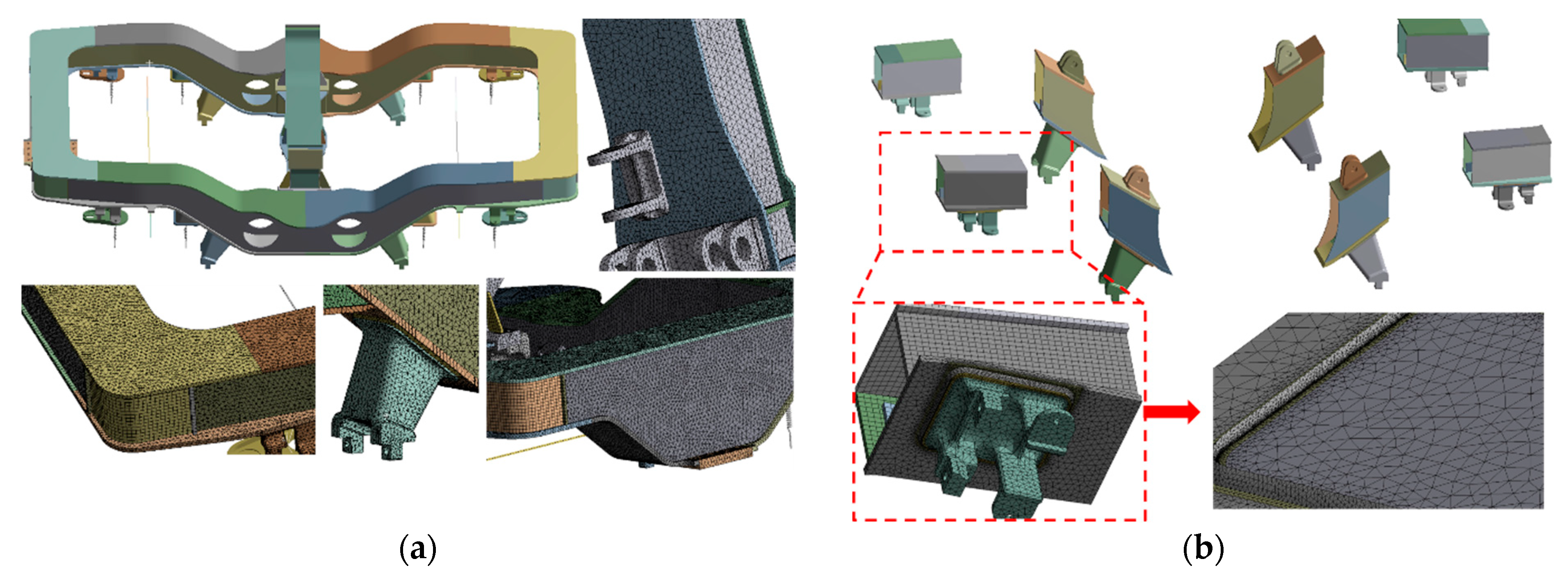
2.1. Bogie Frame Model and Its Mesh Generation Scheme
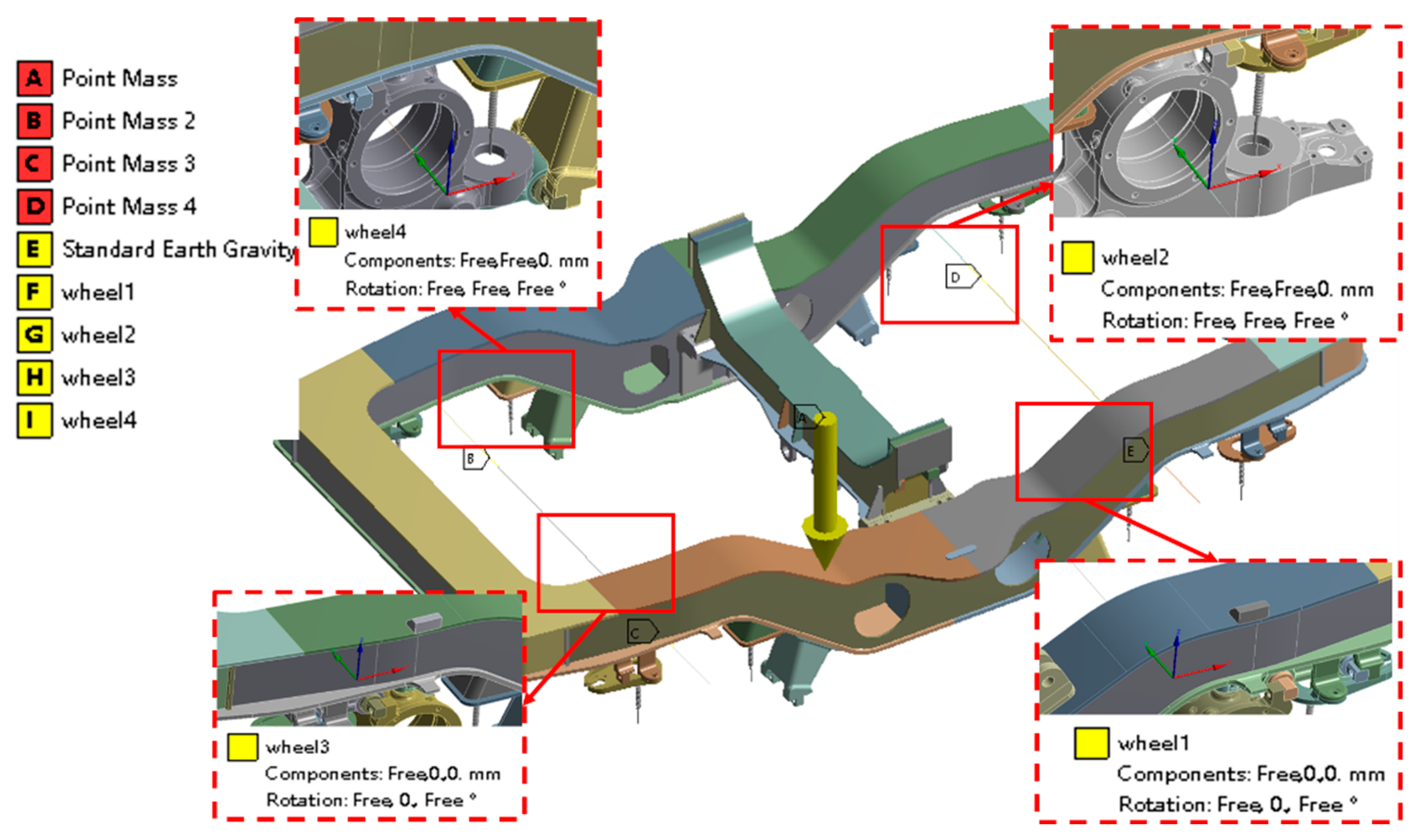
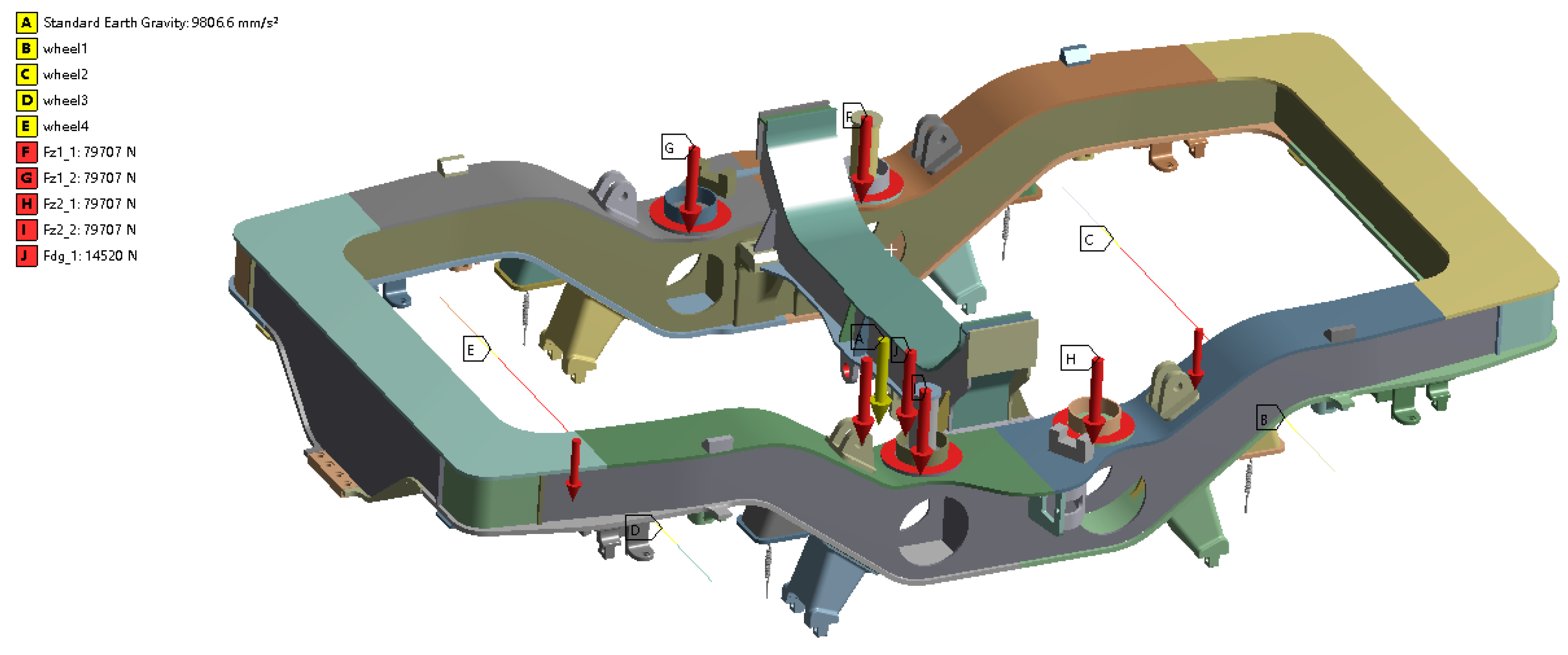
2.2. Boundary Conditions of Bogie Frames and Load Application Locations
- A vertical constraint was applied to the rolling circle of the simulated wheelset;
- A transverse constraint was applied to the rolling circle on one side of the wheelset;
- A longitudinal constraint was applied to the traction pin;
- The vertical load acting on the side sills was applied to the base plate of the secondary rubber-metal pad of the frame;
- The transverse load acting on the side sills was applied to the base plate of the secondary rubber-metal pad and the secondary transverse stop of the frame;
- The vertical displacement caused by a track twist of either 10‰ or 5‰ was applied at the rolling circle of the wheels in the diagonal simulation.
2.3. Calculated Basic Loads on the Bogie Frame According to the UIC Standard
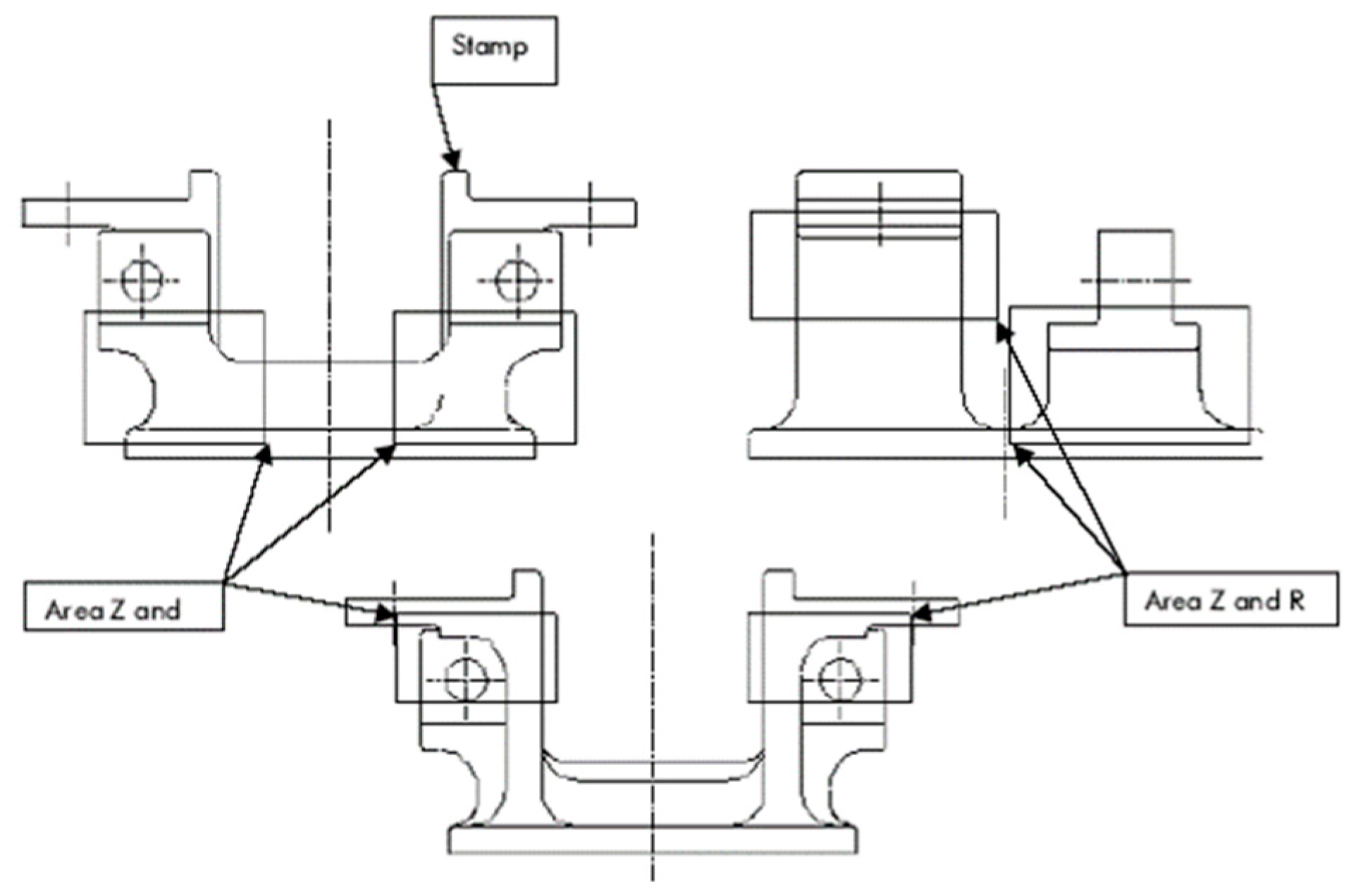
2.4. Research Scheme Used to Assess the Influences of Fillet Weld Defects of Traction Rod Brackets

| Serial Number | Type of Weld Defect | Distribution of Defects Loci | Defect Size | |
|---|---|---|---|---|
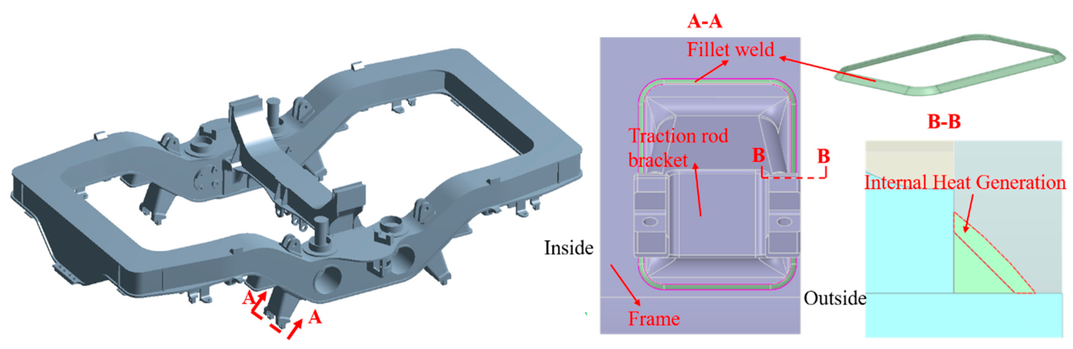
| Attachment Weld of Traction Rod Brackets | Cross-Section of Welds | |||
| 1 | No defects (Figure 6a) | / | / | / |
| 2 | Clearance at weld roots (Figure 6b) | A clearance of 1.7 mm outside the traction rod brackets on the bogie frame | / | Clearance h = 1.7 mm |
| 3 | Incomplete fusion of sidewalls (Figure 6c) | Bottom arc corner and midline of the traction rod brackets (Figure 6f) | Incomplete fusion near the weld root in the side of the fusion surface of the traction rod brackets | Length l = 10 mm along the weld length direction and height h = 2 mm |
| 4 | Incomplete penetration at weld roots (Figure 6d) | Bottom arc corner and midline of the traction rod brackets (Figure 6f) | Incomplete penetration near the weld root in the side of the fusion surface of the cover plate | Length l = 10 mm along the weld length direction and height h = 2 mm |
| 5 | Pores (Figure 6e) | Two pores are set along the weld length direction at bottom arc corner and midline of the traction rod brackets | Pores near the weld root in the side of the fusion surface of the traction rod brackets | Diameter d = 2 mm and clearance s = 20 mm |
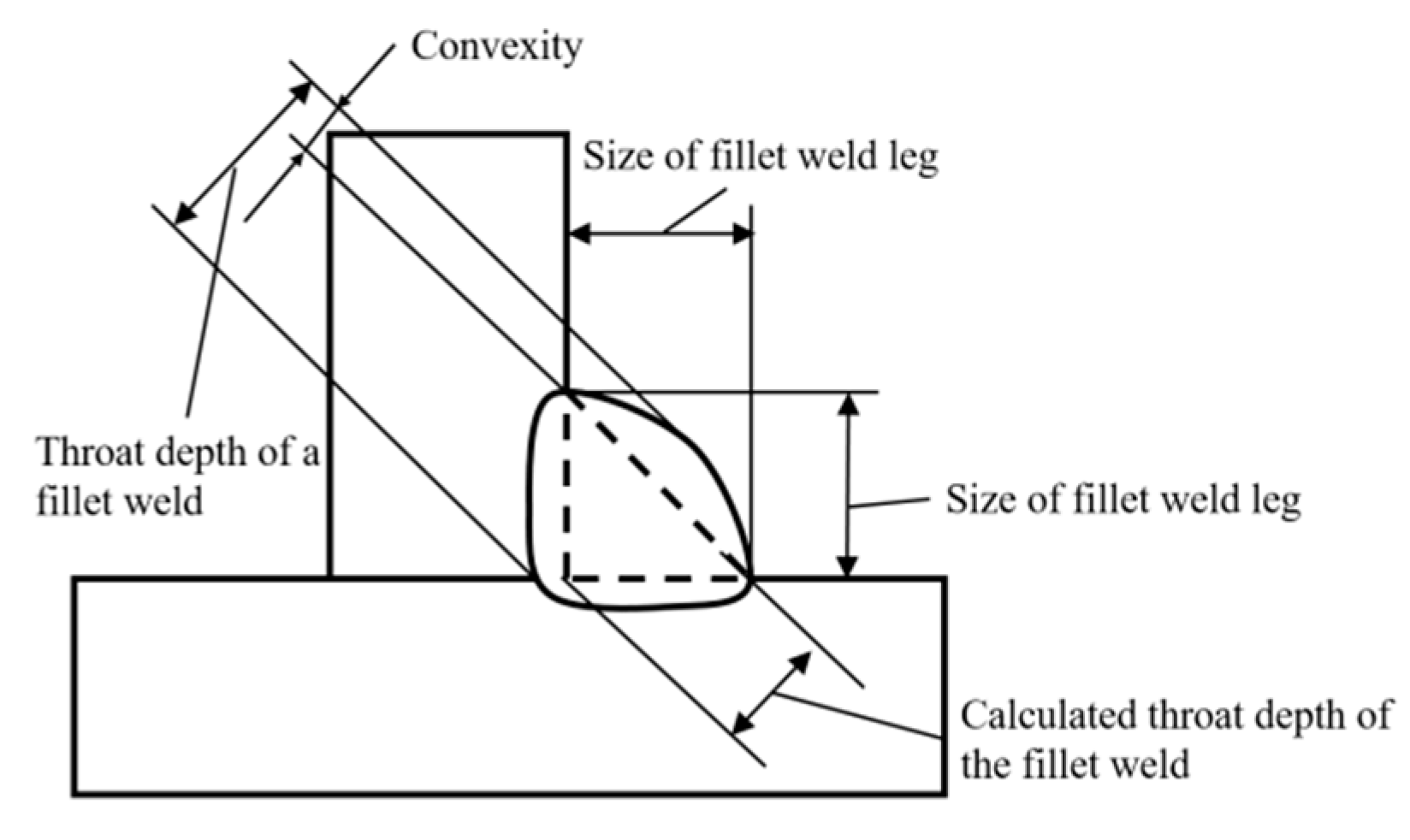
2.5. Research Scheme for Influences of the Throat Depth of Fillet Welds
2.6. Research Scheme for Influences of Residual Stress
2.7. Strength Evaluation of Frame
- 1.
- Evaluation of the static strength
- 2.
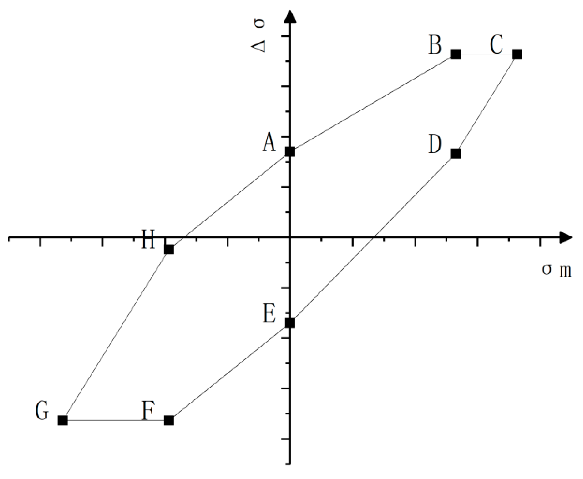
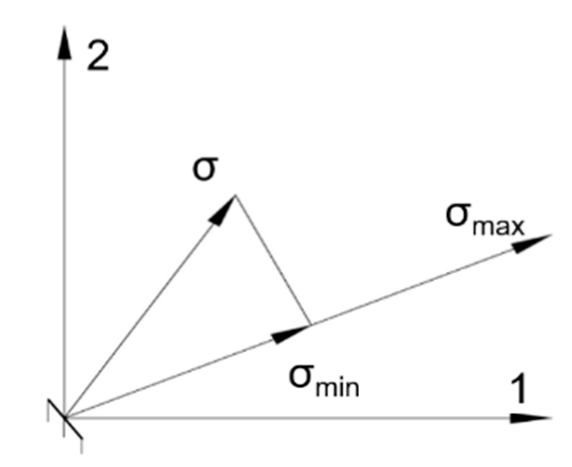
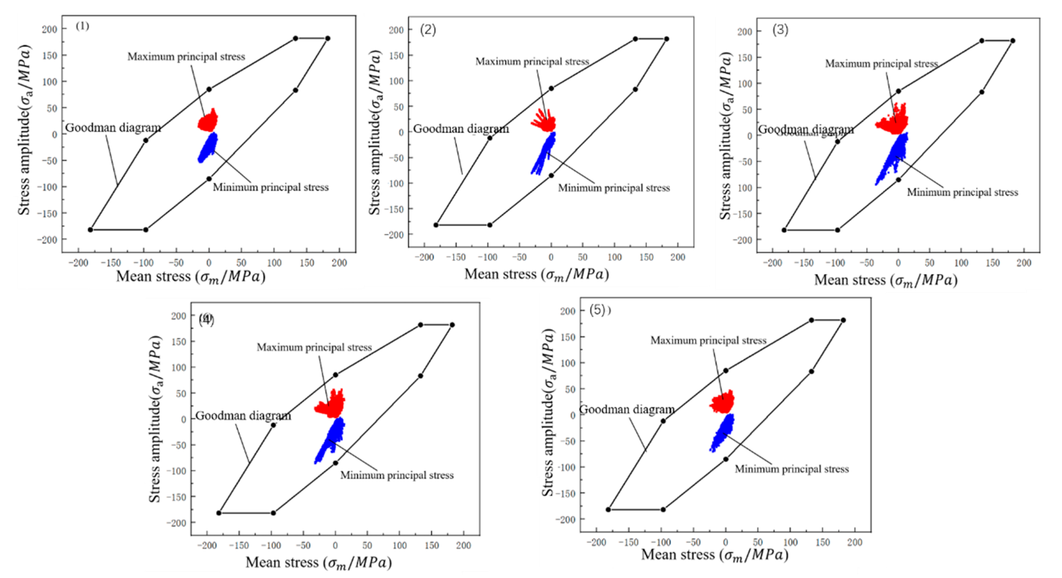
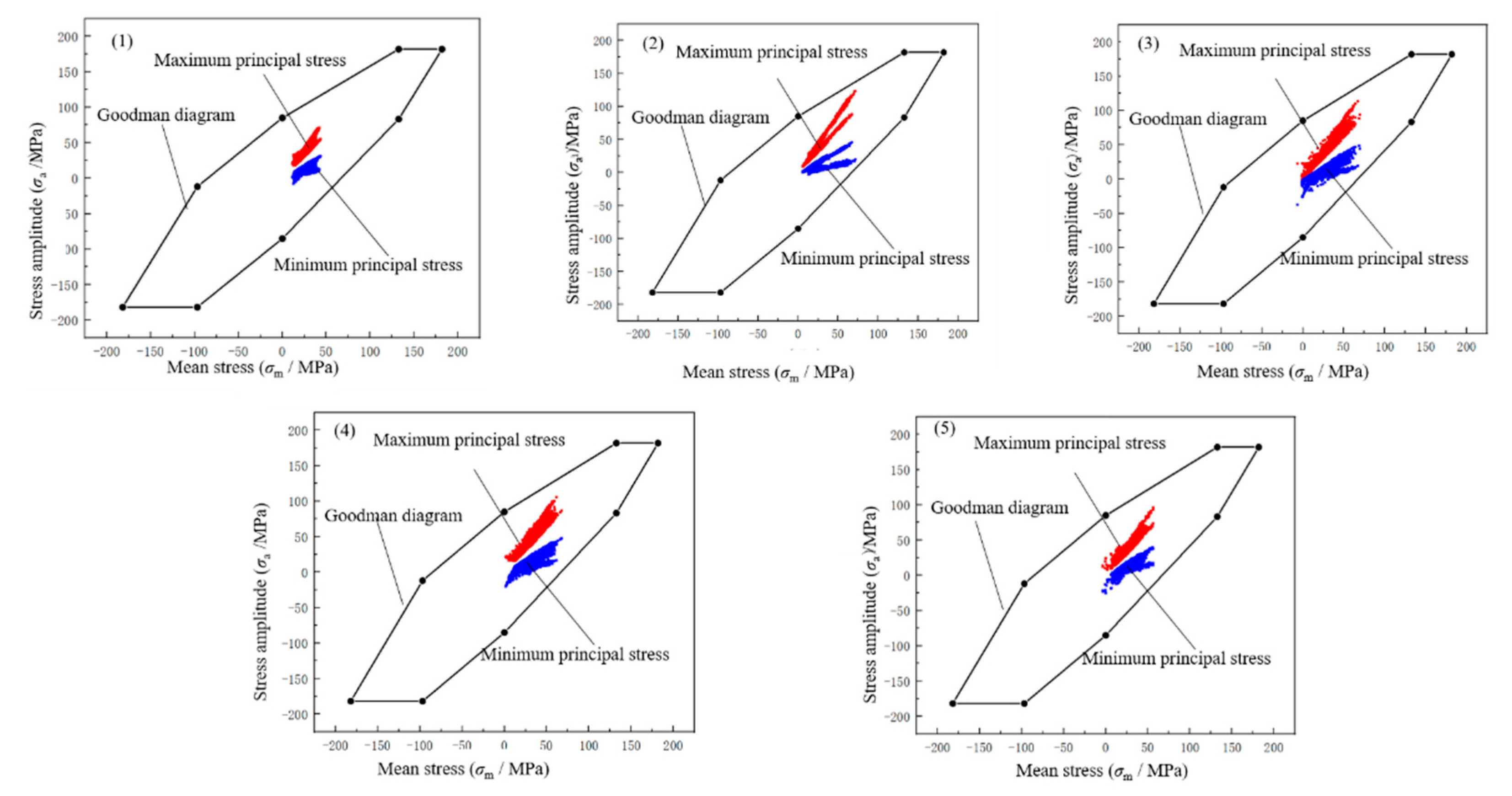
- Evaluation of the fatigue strength based on Goodman diagrams
3. Results and Discussion
3.1. Analysis of the Static Strength under Supernormal Loads
3.2. Analysis Results of the Fatigue Strength under Operational Loads
3.3. Simulation Results for Influences of the Increased Throat Depth of Fillet Welds Due to Repair Welding
3.3.1. Influences of Changes in the Throat Depth of Fillet Welds
3.3.2. Influences of Residual Stress Induced by Repair Welding
4. Conclusions
- (1)
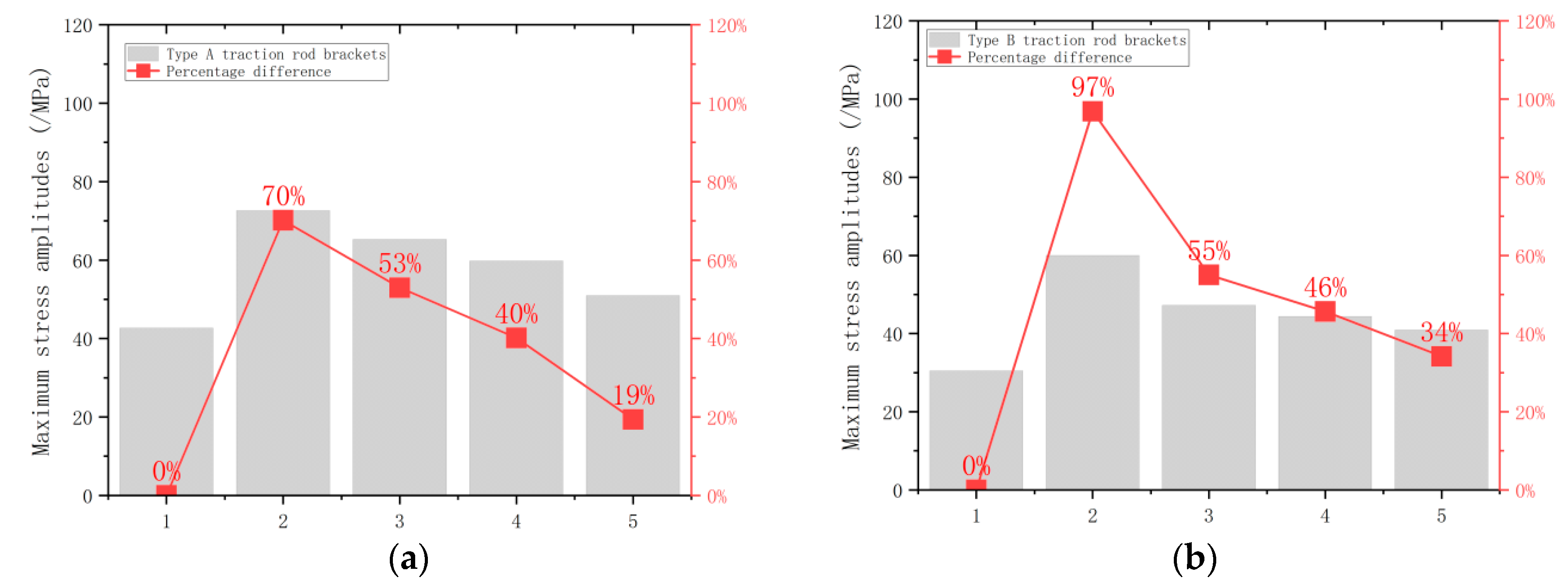
- When there are the maximum clearance at weld roots, maximum incomplete fusion of sidewalls, maximum incomplete fusion at weld roots, and maximum porosity allowable in ISO 5817, the stress amplitude separately increases by 70~97%, 53~55%, 40~46%, and 19~34%;
- (2)
- When various types of defects with the maximum size allowable in the ISO 5817 standard are present in the weld alone, the static and fatigue strengths of fillet welds with a throat depth of 6 mm of the traction rod bracket can still meet the requirement codified in the UIC615-4 standard. The reasons for fatigue failure of fillet welds of the tie rod seat during the design life are complex; analysis shows that in actual fillet welds, defects such as root gap, a lack of fusion, and porosity may occur at the same time, which is one of the possible reasons for fatigue failure of fillet welds during their design life;
- (3)
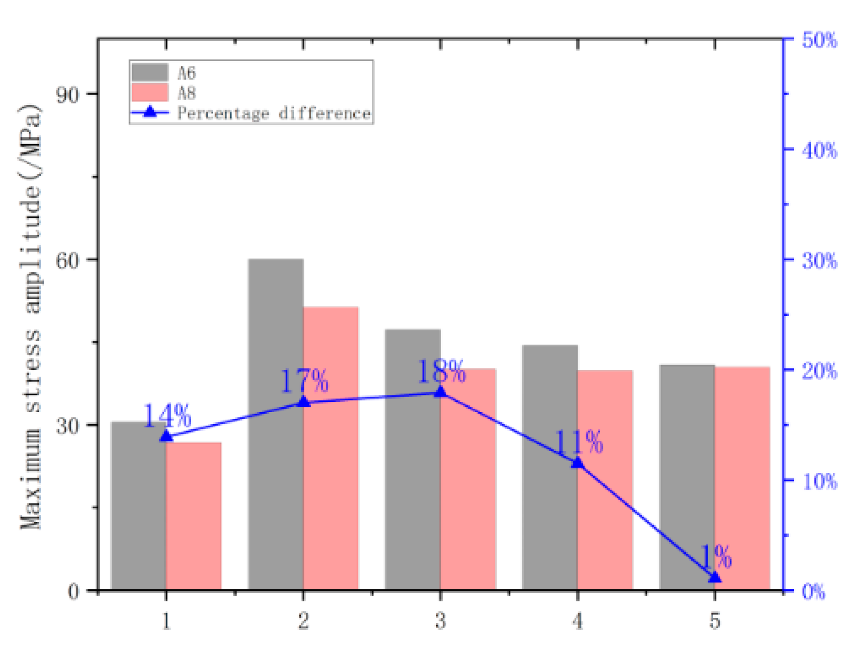
- According to the size of the frame and the traction rod brackets, a strengthening scheme for increasing the throat depth of fillet welds of traction rod brackets to 8 mm was presented. Calculations show that for new structures subjected to overall post-weld stress-relief thermal treatment, the maximum stress amplitude decreases by 5~29% when increasing the throat depth of fillet welds from 6 to 8 mm;
- (4)
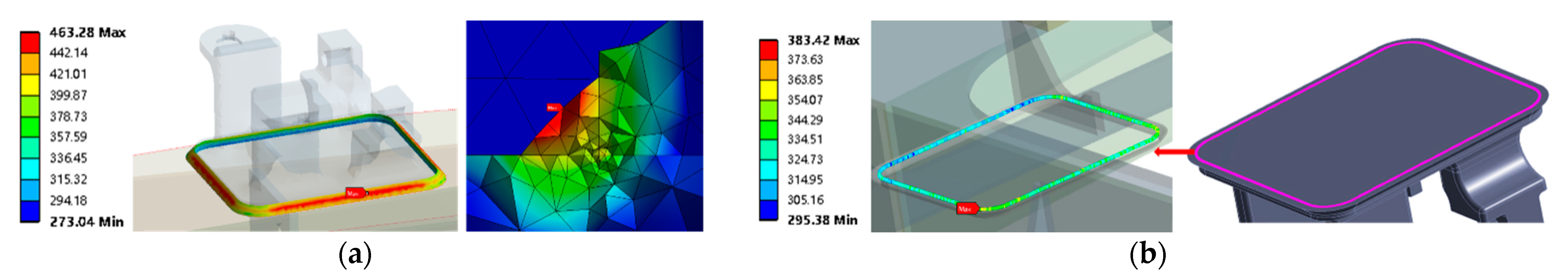
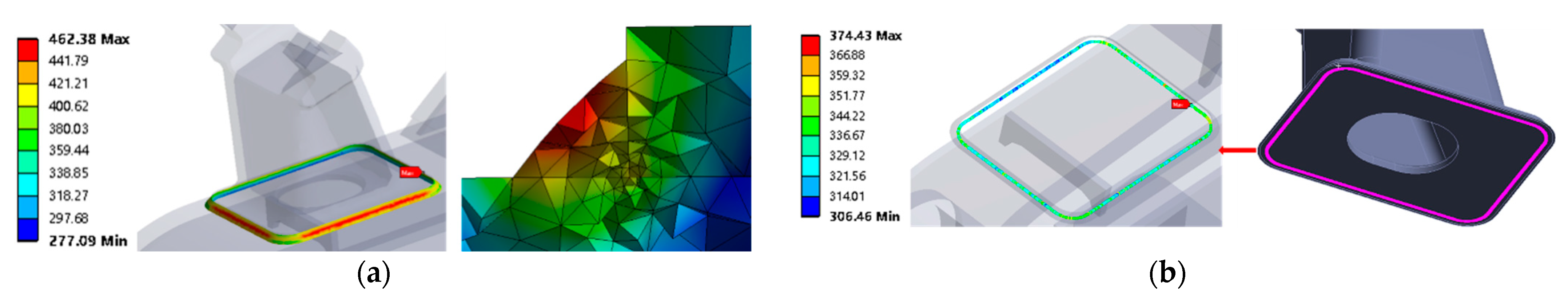
- For structures in service, when the throat depth of fillet welds increases from 6 to 8 mm through repair welding, the peak residual stress at the weld root after repair welding can reach 383 MPa; because overall stress-relief thermal treatments cannot be performed on repair-welded structures, the fatigue strength of repair-welded fillet welds cannot meet the requirements codified in the UIC615-4 standard, so local stress-relief treatments must be applied in the welded zone.
Author Contributions
Funding
Institutional Review Board Statement
Informed Consent Statement
Data Availability Statement
Conflicts of Interest
Appendix A


| Serial Number | Parameter | Value/mm |
|---|---|---|
| 1 | Height from the end of the drawbar frame to the rail surface | 434.5 |
| 2 | Longitudinal distance from the end of the drawbar frame to the bogie center | 2130 |
| 3 | Longitudinal distance from the hoisting point for motor assembly to the center of wheel axle | 1171 |
| 4 | Transverse distance from the hoisting point for motor assembly to the center of wheel axle | 0 |
| 5 | Height from the centroid of the driving device to the rail surface | 619 |
| 6 | Longitudinal distance from the centroid of the driving device to the center of wheel axle | 478 |
| 7 | Transverse distance from the centroid of the driving device to the bogie center | 432 |
| 8 | Wheelbase | 2600 |
| 9 | Transverse spacing of primary spring supports | 2200 |
| 10 | Transverse span of secondary rubber-metal pad | 2160 |
| 11 | The number of wheelsets on each bogie | 2 wheelsets |
| 12 | Wheel diameter | 1250 |
| 13 | Transverse distance from the centroid of the brake to the bogie center (with parking brake) | 746.5 |
| 14 | Longitudinal distance from the centroid of the brake to the center of wheel axle (with parking brake) | 838.3 |
| 15 | Vertical distance from the centroid of the brake to the rail surface (with parking brake) | 700 |
| 16 | Transverse distance from the centroid of the brake to the bogie center | 746.5 |
| 17 | Longitudinal distance from the centroid of the brake to the center of wheel axle | 838.3 |
| 18 | Vertical distance from the centroid of the brake to the rail surface | 625 |
Appendix B
| Load Conditions | Vertical Forces in Each Side of the Frame | Transverse Load | Longitudinal Load | Loads of Driving Devices | Load of Brake Carrier | |||
|---|---|---|---|---|---|---|---|---|
| Left Side Sill | Right Side Sill | Dead Load | Vibration | Motor Torque | ||||
| 1.1 | 159,412.5 | 159,412.5 | 0 | 0 | 35,580 | 0 | 0 | 0 |
| 1.2 | 111,589 | 111,589 | 193,500 | 0 | 35,580 | 0 | 0 | 0 |
| 1.3 | 111,589 | 111,589 | 193,500 | 0 | 35,580 | 0 | 0 | 0 |
| 1.4 | 111,589 | 111,589 | −193,500 | 0 | 35,580 | 0 | 0 | 0 |
| 1.5 | 111,589 | 111,589 | 0 | 0 | 35,580 | 0 | 0 | 0 |
| 1.6 | 111,589 | 111,589 | 0 | 47,500 | 35,580 | 10 g | 11,389 | 0 |
| 1.7 | 111,589 | 111,589 | 0 | 47,500 | 35,580 | −10 g | 11,389 | 0 |
| 1.8 | 111,589 | 111,589 | 0 | −47,500 | 35,580 | 10 g | −11,389 | 0 |
| 1.9 | 111,589 | 111,589 | 0 | −47,500 | 35,580 | −10 g | −11,389 | 0 |
| 1.1 | 111,589 | 111,589 | 0 | −10,025 | 35,580 | 10 g | 0 | 26,025 |
| 1.11 | 111,589 | 111,589 | 0 | −10,025 | 35,580 | −10 g | 0 | 26,025 |
| 1.12 | 111,589 | 111,589 | 0 | 10,025 | 35,580 | 10 g | 0 | 26,025 |
| 1.13 | 111,589 | 111,589 | 0 | 10,025 | 35,580 | −10 g | 0 | 26,025 |
| 1.14 | 111,589 | 111,589 | 0 | 47,500 | 35,580 | 10 g | 45,556 | 0 |
| 1.15 | 111,589 | 111,589 | 0 | 47,500 | 35,580 | −10 g | 45,556 | 0 |
| 1.16 | 111,589 | 111,589 | 0 | −47,500 | 35,580 | 10 g | −45,556 | 0 |
| 1.17 | 111,589 | 111,589 | 0 | −47,500 | 35,580 | −10 g | −45,556 | 0 |
| 1.18 | 111,589 | 111,589 | 0 | 0 | 35,580 | 10 g | 45,556 | 0 |
| 1.19 | 111,589 | 111,589 | 0 | 0 | 35,580 | −10 g | 45,556 | 0 |
| 1.2 | 111,589 | 111,589 | 0 | 0 | 35,580 | 10 g | −45,556 | 0 |
| 1.21 | 111,589 | 111,589 | 0 | 0 | 35,580 | −10 g | −45,556 | 0 |
| 1.22 | 85,837.50 | 85,837.50 | 0 | 0 | 35,580 | 0 | 0 | |
| 1.23 | 79,706.50 | 79,706.50 | 0 | 128,756.25 | 35,580 | 0 | 0 | |
| 1.24 | 79,706.50 | 79,706.50 | 0 | −128,756.25 | 35,580 | 0 | 0 | |
| Load Conditions | Vertical Forces in Each Side of the Frame | Transverse Load | Twisting Load | |
|---|---|---|---|---|
| Left Side Sill | Right Side Sill | |||
| 2.1 | 79,707 | 79,707 | 0 | 0 |
| 2.2 | 71,735.625 | 55,794.375 | 0 | 0 |
| 2.3 | 71,735.625 | 55,794.375 | 122625 | 0 |
| 2.4 | 103,618.125 | 87,676.875 | 0 | 0 |
| 2.5 | 103,618.125 | 87,676.875 | 122,625 | 0 |
| 2.6 | 55,794.375 | 71,735.625 | 0 | 0 |
| 2.7 | 55,794.375 | 71,735.625 | −122,625 | 0 |
| 2.8 | 87,676.875 | 103,618.125 | 0 | 0 |
| 2.9 | 87,676.875 | 103,618.125 | −122,625 | 0 |
| 2.1 | 71,735.625 | 55,794.375 | 122,625 | 5‰ track twist |
| 2.11 | 71,735.625 | 55,794.375 | 122,625 | −5‰ track twist |
| 2.12 | 103,618.125 | 87,676.875 | 122,625 | 5‰ track twist |
| 2.13 | 103,618.125 | 87,676.875 | 122,625 | −5‰ track twist |
| 2.14 | 55,794.375 | 71,735.625 | −122,625 | 5‰ track twist |
| 2.15 | 55,794.375 | 71,735.625 | −122,625 | −5‰ track twist |
| 2.16 | 87,676.875 | 103,618.125 | −122,625 | 5‰ track twist |
| 2.17 | 87,676.875 | 103,618.125 | −122,625 | −5‰ track twist |
| Load Conditions | Vertical Forces in Each Side of the Frame | Longitudinal Load | Loads of Driving Devices | Damper Load | Load of Secondary Vertical Damper | ||
|---|---|---|---|---|---|---|---|
| Left Side Sill | Right Side Sill | Load of Vertical Acceleration of the Motor | Counter-Force of Motor Suspender | ||||
| 3.1 | 79,707 | 79,707 | 138,500 | 43,560 | 39,816 | −108,000 | 20,445 |
| 3.2 | 79,707 | 79,707 | 138,500 | −43,560 | 39,816 | −108,000 | −20,445 |
| 3.3 | 79,707 | 79,707 | −138,500 | 43,560 | −39,816 | 108,000 | 20,445 |
| 3.4 | 79,707 | 79,707 | −138,500 | −435,560 | −39,816 | 108,000 | −20,445 |
| Load Conditions | Vertical Forces in Each Side of the Frame | Longitudinal Load | Load of Driving Device | Damper Load | Load of Secondary Vertical Damper | Normal Force on Each Unit of the Brake | Frictional Force of Each Unit of the Brake | |
|---|---|---|---|---|---|---|---|---|
| Left Side Sill | Right Side Sill | |||||||
| 4.1 | 79,707 | 79,707 | −38,500 | 43,560 | 108,000 | 20,445 | −38,500 | 11,435 |
| 4.2 | 79,707 | 79,707 | −38,500 | −43,560 | −108,000 | −20,445 | −38,500 | 11,435 |
| 4.3 | 79,707 | 79,707 | 38,500 | 43,560 | 108,000 | 20,445 | −38,500 | −11,435 |
| 4.4 | 79,707 | 79,707 | 38,500 | −43,560 | −108,000 | −20,445 | −38,500 | −11,435 |
| Load Condition | Vertical Forces in Each Side of the Frame | Longitudinal Loads of Wheels | ||
|---|---|---|---|---|
| Left Side Sill | Left Side Sill | Left | Right | |
| 5.2 | 79,707 | 79,707 | 24,525 | −24,525 |
| 5.3 | 79,707 | 79,707 | −24,525 | 24,525 |
References
- Huang, Y. Technical characteristics of heavy-duty electric locomotive bogies in China. Electr. Locomot. Urban Rail Veh. 2006, 5, 7–9. [Google Scholar] [CrossRef]
- Chen, G.; Zhou, J. Harmony HX_D1 High Power AC Electric Locomotive Bogies. Electr. Locomot. Urban Rail Veh. 2007, 146, 29–32. [Google Scholar] [CrossRef]
- Zhang, Z.; Feng, B.; Jia, F.; Zhang, W. Bogie for HXD2 AC Drive Heavy Freight Electric Locomotive. Locomot. Electr. Transm. 2008, 202, 6–7+11. [Google Scholar] [CrossRef]
- Opala, M.; Korzeb, J.; Koziak, S.; Melnik, R. Evaluation of Stress and Fatigue of a Rail Vehicle Suspension Component. Energies 2021, 14, 3410. [Google Scholar] [CrossRef]
- Bosso, N.; Magelli, M.; Zampieri, N. Dynamical Effects of the Increase of the Axle Load on European Freight Railway Vehicles. Appl. Sci. 2023, 13, 1318. [Google Scholar] [CrossRef]
- Wu, B.; Chen, G.; Lv, J.; Zhu, Q.; Zhao, X.; Kang, X. Effect of the axlebox arrangement of the bogie and the primary suspension parameters on the rail corrugation at the sharp curve metro track. Wear Int. J. Sci. Technol. Frict. Lubr. Wear. 2019, 426–427, 1828–1836. [Google Scholar] [CrossRef]
- Zheng, F.; Xiao, X.; Zhang, H.; Zhang, G. Strength simulation and experimental comparison study of central traction device. Machinery 2022, 49, 31–37. [Google Scholar] [CrossRef]
- Sun, J.; Liu, Z.; Lu, Z. Technical analysis of the basic braking device for railway freight car bogies. Railw. Roll. Stock 2018, 38, 62–65. [Google Scholar] [CrossRef]
- Zhang, L.; Zhu, K.; Li, Y.; Fu, J.; Zhang, Y. Research on the Fatigue Strength of Bogie Frames Based on DVS 1612 and JIS 4270 Standards. J. Dalian Jiaotong Univ. 2023, 44, 22–26+52. Available online: https://kns.cnki.net/kcms2/article/abstract?v=3uoqIhG8C44YLTlOAiTRKu87-SJxoEJu6LL9TJzd50nogfWsZUg9UQxrObWiQe5lIWIB1-IfEPYjLwmjJC1-B7zxX_L_xl7U&uniplatform=NZKPT (accessed on 14 March 2023).
- Liu, S.; Yang, G.; Xiao, S.; Yang, B.; Zhu, T. Comparative analysis of fatigue strength of welded frames based on UIC and JIS standards. Locomot. Electr. Transm. 2019, 271, 91–94. [Google Scholar] [CrossRef]
- Fan, Q.; Wang, T.; Zhang, Y.; Wang, Y.; Liu, D. Static and fatigue strength analysis of the 120 km/h subway bogie frame. Weld. Technol. 2022, 51, 48–53. [Google Scholar] [CrossRef]
- Wang, W.; Zheng, J.; Yan, C.; Song, X.; Xu, Z. Optimization design of subway frame traction rod seat model based on finite element analysis. Locomot. Electr. Drive 2020, 273, 140–143. [Google Scholar] [CrossRef]
- Lu, X.; Zhang, X.; Ma, T.; Li, M.; Deng, S. Static strength and fatigue strength analysis of the bogie frame of a B-type subway vehicle. Weld. Technol. 2023, 52, 29–32. [Google Scholar] [CrossRef]
- Jeon, W.; Shin, K.; Kim, J. A study on evaluation of fatigue strength of a GFRP composite bogie frame for urban subway vehicles. Adv. Compos. Mater. 2013, 22, 4. [Google Scholar] [CrossRef]
- Liu, S.; Wang, G. Strength analysis of the new CFRP subway bogie frame. Mech. Manuf. Autom. 2023, 52, 100–104. [Google Scholar] [CrossRef]
- Mozafari, F.; Thamburaja, P.; Srinivasa, A.R.; Moslemi, N. A rate independent inelasticity model with smooth transition for unifying low-cycle to high-cycle fatigue life prediction. Int. J. Mech. Sci. 2019, 159, 325–335. [Google Scholar] [CrossRef]
- Mozafari, F.; Thamburaja, P.; Moslemi, N.; Srinivasa, A. Finite-element simulation of multi-axial fatigue loading in metals based on a novel experimentally-validated microplastic hysteresis-tracking method. Finite Elem. Anal. Des. 2021, 187, 103481. [Google Scholar] [CrossRef]
- Carone, S.; Corigliano, P.; Epasto, G.; Moramarco, V.; Palomba, G.; Pappalettera, G.; Casavola, C. Innovative Approach for the Evaluation of the Mechanical Behavior of Dissimilar Welded Joints. Metals 2022, 12, 2039. [Google Scholar] [CrossRef]
- Xie, X.; Jiang, W.; Pei, X.; Niu, R.; Li, X.; Dong, Z.; Wan, Y.; Liu, B. Synthetical effect of material inhomogeneity and welding defects on fatigue behavior of 2205 duplex stainless steel cruciform welded Joints: Experiments and Life-prediction model. Int. J. Fatigue 2023, 168, 107472. [Google Scholar] [CrossRef]
- Wang, W.; Zhou, Z.; Huang, B.; Du, J. Structural dynamic response of a locomotive hydraulic damper with welding imperfections. J. Phys. Conf. Ser. 2021, 1983, 012030. [Google Scholar] [CrossRef]
- Cao, J.; Ma, W.; Pang, G.; Wang, K.; Ren, J.; Nie, H.; Dang, W.; Yao, T. Failure analysis on girth weld cracking of underground tee pipe. Int. J. Press. Vessel. Pip. 2021, 191, 104371. [Google Scholar] [CrossRef]
- Ma, C.; Long, J.; Zhang, L.; Joo, N.S. HXD2 locomotive bogie pull rod seat fillet weld fatigue failure mechanism. Welding 2022, 589, 40–47. [Google Scholar] [CrossRef]
- Seo, J.-W.; Kwon, S.-J.; Lee, C.-W.; Lee, D.-H.; Goo, B.-C. Fatigue strength and residual stress evaluation of repair welding of bogie frame for railway vehicles. Eng. Fail. Anal. 2021, 119, 104980. [Google Scholar] [CrossRef]
- Goo, B.-C. Effect of Post-Weld Heat Treatment on the Fatigue Behavior of Medium-Strength Carbon Steel Weldments. Metals 2021, 11, 1700. [Google Scholar] [CrossRef]


| Material | Elastic Modulus/MPa | Poisson’s Ratio | Yield Strength/ MPa | Ultimate Strength/ MPa | Coefficient of Thermal Expansion/°C | Specific Heat kJ/kg °C | Thermal Conductivity W/m °C | Surface Coefficient of Heat Transfer W/m2 °C | |
|---|---|---|---|---|---|---|---|---|---|
| Frame | S355J2 | 2 × 10⁵ | 0.3 | 355 | 470 | 1.1 × 10⁻⁵ | 460 | 50 | 100 |
| traction rod bracket | E300-520-MS C2 | 2 × 10⁵ | 0.3 | 300 | 520 | 1.1 × 10⁻⁵ | 460 | 50 | 100 |
| Inflection Point | Mean Stress σm | Stress Amplitude σa |
|---|---|---|
| A | 0 | |
| B | ||
| C | ||
| D | ||
| E | 0 | |
| F | ||
| G | ||
| H |
| Model | Type A Traction Rod Brackets | Type B Traction Rod Brackets | |
|---|---|---|---|
| 1 | Fillet weld A6 of the existing welded structure | 42.68 | 30.49 |
| 2 | Clearance (h = 1.7 mm) | 72.63 | 60.02 |
| 3 | Incomplete fusion of sidewalls (l = 10 mm, h = 2 mm) | 65.28 | 47.27 |
| 4 | Incomplete penetration of weld roots (l = 10 mm, h = 2 mm) | 59.82 | 44.41 |
| 5 | Pores (d = 2 mm, s = 20 mm) | 50.95 | 40.91 |
Disclaimer/Publisher’s Note: The statements, opinions and data contained in all publications are solely those of the individual author(s) and contributor(s) and not of MDPI and/or the editor(s). MDPI and/or the editor(s) disclaim responsibility for any injury to people or property resulting from any ideas, methods, instructions or products referred to in the content. |
© 2023 by the authors. Licensee MDPI, Basel, Switzerland. This article is an open access article distributed under the terms and conditions of the Creative Commons Attribution (CC BY) license (https://creativecommons.org/licenses/by/4.0/).
Share and Cite
Xie, M.-X.; Wei, Y.-Q.; Xin, Q.-K.; Li, L.-X.; He, Y.-M. Fatigue Resistance of Fillet Welds of Traction Rod Brackets on a Locomotive Bogie Based on International Union of Railways Standards and Improvement Measures Adopted. Appl. Sci. 2023, 13, 5494. https://doi.org/10.3390/app13095494
Xie M-X, Wei Y-Q, Xin Q-K, Li L-X, He Y-M. Fatigue Resistance of Fillet Welds of Traction Rod Brackets on a Locomotive Bogie Based on International Union of Railways Standards and Improvement Measures Adopted. Applied Sciences. 2023; 13(9):5494. https://doi.org/10.3390/app13095494
Chicago/Turabian StyleXie, Miao-Xia, Yuan-Qi Wei, Qi-Ke Xin, Li-Xia Li, and Yu-Min He. 2023. "Fatigue Resistance of Fillet Welds of Traction Rod Brackets on a Locomotive Bogie Based on International Union of Railways Standards and Improvement Measures Adopted" Applied Sciences 13, no. 9: 5494. https://doi.org/10.3390/app13095494
APA StyleXie, M.-X., Wei, Y.-Q., Xin, Q.-K., Li, L.-X., & He, Y.-M. (2023). Fatigue Resistance of Fillet Welds of Traction Rod Brackets on a Locomotive Bogie Based on International Union of Railways Standards and Improvement Measures Adopted. Applied Sciences, 13(9), 5494. https://doi.org/10.3390/app13095494