Abstract
Wooden nail-stitched crates are widely used for fruit transportation. Bad stapled nails are transformed into severe product damage that creates stains on the crate due to its juice. In consequence, the final customer depreciates the product because the quality product is in doubt. Human visual inspection of badly stapled nails is a non-effective solution since constant criteria are difficult to reach for all of crate production. A system for the in-line inspection based on a conveyor belt of badly stapled nails in stitched crates is presented. The developed inspection system is discussed with the definition of the computer vision system used to identify fails and the description of image processing algorithms. The experiments are focused on a comparative analysis of the performance of five state-of-the-art classification algorithms based on a deep neural network and traditional computer vision algorithms, highlighting the trade-off between speed and precision in the detection. An accuracy of over 95% is achieved if the user defines the nail location in the image. The presented work constitutes a benchmark to guide deep-learning computer vision algorithms in realistic applications.
1. Introduction
Logistic management operations and consumer behaviors during retail and consumption are largely related to significant food loss and waste. Postharvest waste includes losses from transporting, handling, and storing food products before reaching the customer. Fruit and vegetable postharvest waste is quantified between 30% and 50% of the initial harvested or produced product [1,2,3]. Vibrations and shocks are responsible for failure or quality losses in fresh fruit, vegetables, or electronic goods. Considering the high values of postharvest losses of all food that grows, increased attention is paid to this topic. New technologies are emerging for preventing food and vegetable losses, including technological innovations in the manufacturing and quality control of packages, helping to maintain the product quality from the time it leaves the grower until consumption [4].
Packaging is vital to protect food when it moves along the supply chain to the consumer and prevents food losses and waste [5]. According to [6], the main function of packaging is to protect and distribute the right product to the right end-user in a safe, cost-efficient, and user-friendly way. The “retail or consumer package” is a primary package and generally refers to a ready-to-sell package that contains the sales unit. It protects the product from physical damage, maintains food safety (is clean and protects against dust, dirt, and contamination from microorganisms), facilitates the display of printed information, and enables the extension of the shelf life of the product (creates a high-humidity environment that reduces water loss and shrinkage or a unique gas environment with low O2 and high CO2) [5]. Packaging materials are various types of plastic boxes, films, wood, corrugated, and, recently, edible coatings, as well as waxes based on proteins, lipids, polysaccharides, and their composites [7].
Wooden crates are commonly used for fruits and vegetables. Wood packaging is renewable, recyclable, and holds environmental advantages. The carbon footprint associated with wood is low compared to other materials. Other advantages of wooden packaging are its low cost, good strength, stiffness for the price, and high friction to minimize freight movement, as well as being quick and easy to make, customize, and repair and being available globally. From the point of view of the product, it offers protection from damage, good ventilation, and fast pre-cooling.
A wooden crate consists of rigid corners with planks nailed or stretched against those corners. Stitched crates are made of thin (3–4 mm) pieces of wood stitched together. Corner pieces, mostly triangular, provide the necessary strength to stack crates. Since the wood has chips and nails used to join the wood pieces, the manufacturing process of stitched crates must be carefully supervised to avoid sharp elements on its surface. Any sharp element in the stitched crate surface is transformed into product damage. Badly stapled nails are the main source of sharp elements in the stitched crate’s surface. They appear due to stapling machine malfunctions leaving the nail up. Badly stapled nails appear as sharp objects that seriously damage the stitched crate’s fruits. Consequently, product damages create stains on the crate due to its juice. The crate’s appearance seriously deteriorates, and the final customer depreciates the product because its doubtful quality.
1.1. Motivation
Nowadays, human visual inspection is performed to detect bad stapled nails in the manufacturing process of stitched crates. Human visual review criteria depend on the person doing the inspection and going deeper, it also depends on the hour of the day since human attention changes during the day. Moreover, it is not possible to inspect 100% of the production. Consequently, human classification errors cause stitched crates with badly stapled nails to be sent to final customers. The result is product losses and a loss of credibility of the stitched crates manufacturer with its customer. Finally, it affects the prestige of the stitched crates supplier [8]. To resolve this issue, constant criteria in inspecting stitched crates and 100% of production inspection are necessary.
Automatically detecting badly stapled nails in a continuous production system of stitched crates is complex. A nail is badly stapled when it protrudes from the surface of the wood. Considering the metallic features of the nails, it may be thought that any sensor with inductive technology could solve this task. However, inductive sensors can detect nails in the wood, but they do not detect the shape of the nail. Consequently, this technology does not allow us to determine if the nail is badly stapled. This technology would be very useful if it were necessary to detect the presence of the nail, but this is not the case. Sensors with other technology principles such as capacitive, photoelectric, ultrasonic, or hall effects cannot detect bad stapled nails because they are not sensitive to their features.
Revisiting the area of intelligent sensors, computer vision appears as the first candidate to solve this task. Computer vision uses digital images to interpret, understand, and process visually perceivable objects. The camera could be adjusted to obtain images in which it is possible to detect the nail and its shape. Moreover, computer vision systems accomplish monotonous and repetitive classification tasks faster, without human intervention. Consequently, classification errors are minimized, leaving no room for faulty products and saving much money. Since the stitched crate’s production is continuous, computer vision can inspect 100% of the crates under constant criteria. Moreover, an image of all manufactured products is stored and can be used afterward in case of customer complaints. The use of computer vision reduces manufacturing costs and substantially increases the quality of manufactured stitched crates.
1.2. Related Work
To carry out a good segmentation of images to recover the silhouette of the nail, it is necessary to control the lighting and have a uniform background. In addition, the color of the nail and the color of the wood influence the detection of silhouettes since the pixel intensity is used in the threshold process. To solve this color problem, some approaches convert the color space of the image from RGB (Red-Green-Blue) to HSV (Hue-Saturation-Value) or YUV (Luminance-Blue Projection-Red Projection), where nail and wood color is easier to define [9].
Other techniques to solve the lighting problem, changes in the color of the nail and wood, and controlled backgrounds are based on edge detection. Edge detection uses the image intensity gradient and increases robustness against changes in lighting and the color of nails and wood. The edges of the image are highlighted with its gradient. Consequently, with the edge analysis, features are highly dependent on the shape of the nail and do not depend on its pixels’ pixel. The feature-oriented gradient histogram technique allows for the classification of nails with different colors and lighting.
In the last decade, the results of image and vision computing tasks have significantly improved using artificial neural networks (ANN) [10]. ANN are extensively used in object recognition in images, addressed as a subproblem in pattern recognition. Pattern recognition is the study of how machines understand the nearby environment and how to distinguish a pattern of interest from a general background. [11,12] estimates that approximately 80% of the work done with ANN is related to pattern recognition tasks. A series of neural network architectures for object recognition have been proposed. One architecture is based on Continuous Time Scale Recurrent Neural Networks (CTRNN) [13,14], including Multi-timescale Recurrent Neural Networks (MTRNN) [15].
Moreover, following cognitive modeling, the learning architectures and algorithms appear as an extension using neural network modeling. Deep learning architectures allow for the building of many layers of information processing stages in deep architectures for pattern classification and features or for representational learning [16,17].
Inspired by the complex layered organization of the cerebral cortex, the deep learning approach to neural networks appears. In this case, the fundamental feature of cortical computation is represented by deep-layered processing. It is believed to be the key feature in studying human cognition. Language modeling and cognitive processing applications have been successfully solved using deep learning approaches. In these applications, structured and abstract representations can be included, unsupervised from sensory data, through learning in deep neural networks (for an overview, see [18]). Deep learning architectures allow the efficient building of many layers of information processing stages in deep architectures. They benefit pattern classification and learning characteristics or representations [19,20]. Deep learning architectures, such as deep belief networks (DBNs) and convolutional deep neural networks, have obtained impressive results in several areas. They have exceeded the state-of-the-art algorithms in various tasks, such as computing vision [21] and human action recognition [9].
The main contribution of this paper is to present the efficiency of using computer vision algorithms to perform an automatic visual inspection system for badly stapled nails in stitched crates. The contribution of this work is to show how to build the automatic inspection system and the results of the experiments of detection of badly stapled nails using traditional computer vision algorithms and novel deep neural network architectures. This work establishes a comparative benchmark to reduce the resources needed to include novel deep learning algorithms in badly stapled wooden crate inspection, motivated by the necessity of inspecting 100% of crate production.
Section 2 presents how the computer vision system is configured to obtain images that discriminate between well and badly stapled nails. This section describes the difficulties in extracting some scale and time-invariant characteristics to decide if the nail is well or badly stapled. Section 3 describes the results computed with the training of different neural networks, with the precision of classification, loss, and confidence matrices, and discusses the results. With the AlexNet [21], as a simple CNN to classify images of nails, the SSD-MOBILENET [22], SSD-RESNET, FASTER-RCNN-RESNET [23], and FASTER-RCNN-INCEPTION [24] are tested. Finally, Section 4 concludes the article.
2. Materials and Methods
The computer vision system was designed to inspect the nails of stitched crates such as the one shown in Figure 1.
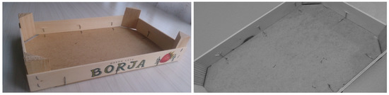
Figure 1.
Stitched crates with nails. Monochrome images.
2.1. Working Principle and Measurement Issues
Two techniques are compared to detect badly stapled nails. The first is based on traditional computer vision techniques that obtain poor detection rates. The second is based on novel neural network architectures that improve the results significantly. The following sections explain both methodologies in detail.
2.1.1. Using Traditional Computer Vision Techniques
As mentioned in Section 1.2, the digital image quality determines the success of a computer vision system. Using traditional computer vision techniques, the image quality is defined as the difference in pixel luminosity between those pixels that belong to the nail and those that do not represent the nail in the image. If features of nail pixels remain similar through images, high rates in detection and classification are possible using traditional computer vision classifiers such as Bayesian classifiers. Moreover, the detection and classification algorithms will be simpler and easier to execute quickly on a computer. Note that if the stitched crate production is 60 per minute, the quality control process should be done in under 1 s per stitched crate. The execution time of a complex computer vision algorithm could be over 1 s, and it will be useless for the current application.
In consequence, to obtain images in which features of the nail pixels remain, the relative location of the camera, the stitched crate, and the illumination are crucial. Special care should be taken in this step because it represents the success of the computer vision application. Shadows and glitters that change in different images could induce failures in the classification algorithm. In this case, a good quality image to detect badly stapled nails in stitched crates needs the inspection area to be illuminated with a constant intensity and a constant location of the light source over time. This will avoid shadows and glitters; if they appear, they will be a nail feature under some conditions that help detect them.
The aim is to capture images where the nail’s appearance is similar to detect errors with the simpler code that needs a shorter execution time. If image acquisition issues are not considered, the complexity of the nail detection algorithm is increased, and it will require a longer execution time. Since this is an in-line inspection system, it is designed to accomplish all image acquisition requirements to obtain stable images that help to reduce the wrong classification rate.
Several types of illumination and camera locations were tried, such as direct, indirect, lateral, and structured illumination, to decide which reinforces the features of a bad stapled nail in the image and which remains over thousands of images. The aim is to obtain a histogram where pixels representing the set of nails’ luminosities are separated from the remaining pixels in the image. Figure 2 shows the image using structured lighting projecting a straight line. In this case, pixels that belong to the straight line have a different illumination than the remaining pixels. With this type of illumination, a projected straight line should remain if no breaks occur in the crate surface.
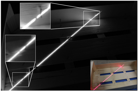
Figure 2.
Crates are illuminated with structured lighting projecting a straight line. Breaks in the straight line define the presence of a badly stapled nail. The top left corner shows the ROI of the stitching area where a badly stapled nail is. In the stitching area, the straight line remains if the nail is correct. In this case, a straight line is broken, as it is shown in the ROI of the image. This means that the nail is badly stapled. The left-down corner shows an example of bad detection with the criteria of a broken straight line. In this case, a splinter broke the straight line.
If the ROI with the nail is analyzed, a discontinuity appears in the straight line, as shown in the top left corner of Figure 2. This discontinuity is the feature to detect the badly stapled nail. Using traditional computer vision algorithms, the discontinuity of a straight line is used to train Bayesian or nearest neighbor classifiers that identify the nail as badly or correctly nailed.
From the point of view of the image processing algorithm, the classification of nails in the image using this feature is very hard work with a low hit ratio as shown in the Section 3 Results. Depending on the deformation of the badly stapled nail, the straight-line discontinuity does not appear. Moreover, discontinuity appears if the wood is not plane and has some splinter, and a false badly stapled nail is detected. In consequence, since this image acquisition system is complex and the classifier ratio is poor, this scheme is discarded, and a new one where ANN is used is proposed.
2.1.2. Using Novel Neural Networks Architectures
From a practical point of view, deep neural network classifiers use supervised learning to adjust thousands of parameters. The supervised learning method requires huge quantities of correctly labeled images of nails to feed the training process. A rectangle defines the position of the nail in the image, and it is labeled as a correctly or badly stapled nail. To obtain this number of labeled nails in images, first, many images of the stitched crater should be captured under similar conditions. These images are captured when the system is built and working in a continuous inspection. Second, manual work is needed to define the rectangle in the image where both types of nails are (correctly or badly stapled) [25]. Using images of labeled nails, the classifier is trained to detect and classify nails.
The configuration proposed in Figure 3 is used to acquire images to detect badly stapled nails in wooden crates using ANN. Figure 3 shows the submitted image to classify nails where the camera is located in a zenithal point of view over the crate. The crate is illuminated with indirect lighting to avoid shadows and brightness as much as possible. The yellow boxes represent the ROIs in the image that are analyzed with the algorithm that does not search nails in the image and just classifies nail ROIs as well or badly stapled. Once the ROI is captured, it is rotated to always have the floor of the crate on the right side if necessary. Depending on where the nail is in the crate, its corresponding ROI is rotated 90, 180, or 270 degrees. This operation will help the classifier to reduce the cases of well or badly stapled nails. In case the classification algorithm searches for well or badly stapled nails in the image, ROIs with nails are not defined. Figure 4 shows a set of six nails labeled as well stapled (a) and badly stapled (b), where the ROI is always orientated in the same way. The crate’s floor is on the right side of the ROI in all cases, with the independence of its location in the crate. These nail patterns are used to train the classification algorithm with a predefined ROI. Figure 4c,d shows the labeled well and badly stapled nails, where nail orientation depends on its location in the crate. As before, these patterns are used to train the algorithm that does not need predefined ROIs and detects the nails’ location in the image.
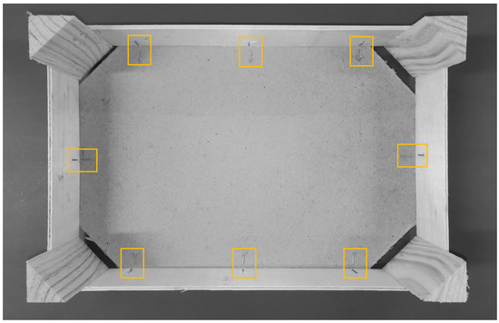
Figure 3.
Proposed image to detect badly stapled nails using ANN. Yellow boxes represent the ROI images that are analyzed in the image.
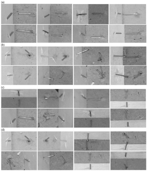
Figure 4.
Labeled stapled nails. (a,b) Good/bad stapling with all ROIs oriented in the same way. The crate’s floor is on the right side of the ROI in all cases, with the independence of its location in the crate. This helps the algorithm to classify nails, but the user has to define nail location in the crate before. (c,d) Good/bad stapling with ROIs defined as it appears in the image. These patterns are used in the training process of the algorithm that searches for well or badly stapled nails in all of the image.
Compared with the traditional computer vision techniques described before, the execution time of deep neural network classifiers is increased significantly. However, improving the computing capacity with specific computing units, the execution time allows for the use of deep neural network classifiers in in-line inspection systems. Moreover, several architectures exist to implement deep neural network classifiers. Variations exist in the inference time and accuracy depending on the chosen model. An exhaustive analysis is found in [26].
2.2. The Instrument
Figure 5a shows a schematic of the built computer vision system’s main parts that work as follows. The in-line sensor detects the presence of a stitched crate in the conveyor. It triggers the camera to capture the image analyzed by the computer unit. Since the camera is triggered by the presence of the stitched crate in the conveyor, the crate is always located identically in all of the images. Consequently, this feature allows for defining the areas in the image where nails are present, and the algorithm just classifies them. In this case, the yellow boxes in Figure 3 represent these ROIs. This definition shortens the algorithm execution time since the algorithm should decide if the nail of the ROI is well or badly stapled only. On the contrary, the user should define the nail location for each different model of the previously manufactured stitched crate in the system. If ROIs with nail presence are not defined previously, the algorithm must decide where the nails are in the image and whether they are badly stapled. Depending on the desired human intervention in the definition of the quality control process of the stitched crate and the time available to conduct the inspection, both solutions are possible. When the image is processed, the classification result is sent to the conveyor control unit to manipulate the stitched crate conveniently, and the captured image and the classification result are sent to a database to be analyzed, if necessary, by the production manager, quality control manager, or to resolve customer complaints if they exist.
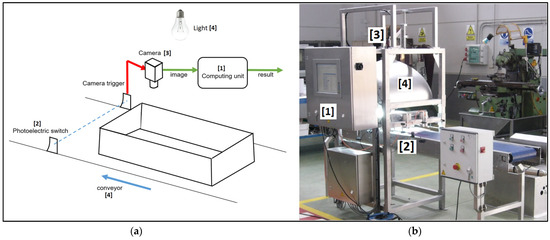
Figure 5.
(a) shows a schematic of the main parts of a computer vision system, and (b) shows the setup of the image acquisition system.
Figure 5b shows the setup of the image acquisition system. One Genie 1410 progressive monochrome camera of 1360 × 1024 pixels is used, marked as (3) in Figure 5. The camera captures the stitched crate, as shown in Figure 3, triggered by the in-line photoelectric sensor, marked as (2). The stitched crate is illuminated with two squared areas led in an indirect lighting configuration (marked as (4) in Figure 5) to avoid shadows and brightness as much as possible. The computing unit is a panel PC based on Intel Skylake-U Core I5 6200U and DDR4 8GB 2133 MHz SODIMM, marked as (1). The computing capacity is increased with an Intel Movidius Neural Compute Stick2 W/Myramid NCSM2485.DK. The camera is connected to the computing unit using the LAN port. The camera, light source, and sensor locations allow for the capturing of the image to inspect the nails shown in Figure 3.
2.3. Deep Learning
ANN is a set of vectors of neurons with an activation function, interconnected with weighted connections and input biased. Weights and biases are adjusted and modified with training to fulfill a specific classification, clustering, prediction, or pattern recognition. In the feed-forward networks, data is arranged in a vector and passes through the layers of neurons. The output of each layer is the input for the next one. Considering that an image is a 2D array, the first layer of the network is a 2D array of neurons that apply a convolutional filter on an image. A convolutional filter is a spatial operator that highlights edges. Several convolutional layers can compute the image’s low, mid, and high-level features. Non-linearity layers follow convolutional layers, and fully connected layers are in the last step. The result is a convolutional neural network (CNN). Several models with CNN architecture have been proposed, such as AlexNet [27], ZF Net (2013), GoogLeNet (2014), VGGNet (2014), ResNet (2015), DenseNet (2016) [28], and CSART [29,30]
Building a model for badly stapled detection from scratch is an arduous task that takes a long time to reach a solution. Thousands of neurons with hundreds of thousands of weights and biases have to be turned into a challenging task. Consequently, to resolve the problem of badly stapled nails, “transfer learning” proposed by [31] is used. Transfer learning consists of using a CNN model that has been trained previously with a different data set. Since CNN architectures contain convolutional layers that can extract inherent properties from images, trained CNN models can be used as a starting point to be retrained with different data to adjust the result to the current problem [32]. Looking for existing models in the state of the art, TensorFlow has an extensive collection of models for object detection pre-trained with existing publicly available datasets such as COCO, Kitti [33], Open Images [34], or Pets [35].
Once the pre-trained model is decided, the training process needs many new labeled images of the current problem where object regions in the picture are defined, and classes are identified. Some automatic labeling algorithms have been described to make this task easier [36]. This new dataset is used to readjust the pre-trained model parameters.
2.4. Training the CNN for Badly Stapled Nails Detection
Referring to the badly stapled nails detection algorithm, a comparison of several CNN classifiers is made. Two cases exist. Since triggered images are used, if the user defines the image area where the nail is, the classification is reduced to decide if this part of the image represents a correctly or badly stapled nail. On the other side, if areas with nails in the image are not defined, the algorithm has to detect areas where nails appear and decide if each nail is stapled correctly. To classify images of nails, a basic convolutional neural network (CNN) is used since it has a low computational cost. To detect nails and to decide if they are correct or not, region convolutional neural network (RCNN) models [37] offer better results. Still, they are more time-consuming than single-shot detector (SSD) models [38]. An SSD model takes one single shot to detect multiple objects within the image. At the same time, an RCNN needs two shots, one for generating region proposals and one for detecting the object of each proposal. In this case, the selected models are the AlexNet [21] as a simple CNN to classify images of nails that the user has defined in the area previously and the SSD-MOBILENET [22], SSD-RESNET, FASTER-RCNN-RESNET [23] and FASTER-RCNN-INCEPTION [24] to detect and classify nails in the entire image.
To train the nails classifier using a supervised learning method, a set of 100 images of different stitched crates were captured. Four hundred nails in images were manually labeled, resulting in 200 labeled as badly stapled nails and 200 labeled as correct. Since nail features remain in different images because the capturing stage is controlled, 400 samples are enough to train a robust classifier. Figure 4 shows samples for each class. Using this data, classifiers’ weights are adjusted using the K-fold cross-validation strategy. The 400 samples are split into 320 for training used to fit the parameters, and 80 for testing, used to provide an unbiased evaluation of a final model fit on the training dataset. To perform the cross-validation strategy, the 320 training samples are split into 8 folds of 40 samples. Each fold is used as a validation set in each round of the training process. It provides an unbiased evaluation of the classifier fit on the training dataset while tuning the classifier parameters, allowing detection overfitting of the classifier to the training dataset. During the training process of the classifier, its classification capabilities are improved, and the training process ends when the classifier overfits training data and classification on testing data does not improve.
After each epoch, the classifier is run with the validation data to compute the total loss and mean Average Precision (mAP) to evaluate the classification performance. Results are shown in Figure 6a–e. Figure 6a–e presents the evolution of the confidence of the classification task on the validation set when the number of network training steps with the training set increases. With all models, the first 500 steps reduce the confidence of the classification by 60%. Afterward, the loss reduction ratio per step is reduced, and the optimization needs 2000 steps more to arrive at 95%. This is because model weights are adjusted at the beginning to classify different images. Consequently, small changes in the neural network weights improve the classification ratio significantly. The network improves its classification abilities with the training until the classification on the validation dataset does not improve further.
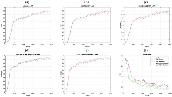
Figure 6.
(a–e) Mean average precision (mAP) over the training steps was evaluated with the validation data set. (f) Models’ losses decrease with the number of training steps.
To analyze the range of classification accuracy with the number of training steps and detect trends in the learning process, models are trained twice. Models losses decreasing with the number of training steps are shown in Figure 6f. The confidence matrix that identifies the amount of well and badly stapled nails are classified into good and bad classes and is defined as follows:
The optimal confidence matrix has ones in the main diagonal, indicating that 100% of good nails were classified as good and 100% of bad nails were classified as bad, and no cross-interference took place.
3. Results
The best model of the training process is selected when the loss is closer to the lowest point and the accuracy is more comparable to its maximum value, based on results shown in Figure 6. Table 1 shows model performances with the elements of the confidence matrix. The confidence matrices show that the model computes better results with the training data than with testing data since it is used to train the model. Considering the ability of the model to classify images of nails, the AlexNet network reports 0 in c12 and c21 elements of the confidence matrix with training data. The same model also has the highest statistics of all the networks in classifying nails with testing data. This is because the location of the nail is defined in the image, and classification is more straightforward. If results using CNN are compared with results using traditional computer vision algorithms, the best results are computed using CNN.

Table 1.
The accuracy and computing time of the classification system depend on the classification algorithm. Accuracy is measured with the confidence matrix parameters. AlexNet can classify all nails correctly and faster, but the user needs to define areas in the image where nails are. The column “Traditional CV” represents the results computed with the method described in the traditional computer vision section.
Similar results of the classifier training and testing process are obtained for the remaining tested models. Usually, between zero to fifteen correct nails are classified as badly stapled, and between zero to twenty badly stapled are classified as valid, depending on the chosen model for the classifier. If traditional computer vision algorithms are used, 50% of the classifications are wrong. These results are expressed as precision and recall in Table 1. Precision is the number of correct classifications divided by the number of all classifications given for correct or badly stapled nails. The recall is the number of correct classifications divided by the number of classifications that should have been returned. Figure 7 shows Table 1 results graphically. Coefficients C11 and C22 should be closer to 1 and C12 and C21 closer to 0 to obtain a good classification performance. Columns of Figure 7 representing values of these coefficients for the AlexNet model satisfy this criterion.
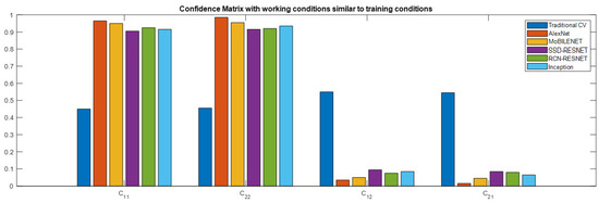
Figure 7.
A graphical representation of the results is shown in Table 1. AlexNet can classify all nails correctly and faster, but the user needs to define areas in the image where nails are. From the point of view of the methods that do not need predefined ROIs to classify nails, the SSD MobileNet model obtains better performance with both well and badly stapled nails. Coefficients C11 and C22 should be closer to 1 and C12 and C21 closer to 0 to obtain a good classification performance.
From the point of view of the methods that do not need predefined ROIs to classify nails, the SSD MobileNet model obtains better performance with both well and badly stapled nails.
Referring to computing time, substantial differences exist. Traditional computer vision algorithms are faster but do not obtain good results. AlexNet is the faster of the CNN models and obtains good performance. However, ROIs, where nails are, must be defined in the image to make the classification proper. If algorithms with no predefined ROIs are compared, they are all over 1 s of computing time, making them unsuitable for an in-line inspection of 60 crates per minute. A computing unit with a higher capacity than the one used in this work will be necessary to improve the computing time of the CNN models.
Table 2.
Results of the confidence matrix when image acquisition conditions change. The first four rows are the results when the angle of view changes. The second four rows show the results of changing the illumination conditions. Four hundred images are used to test the angle of view, and 200 with illumination conditions changed. Compared with Table 1, the results are worse.
| Confidence Matrix | SSD | FASTER-RCNN | ||||
|---|---|---|---|---|---|---|
| AlexNET | MOBILENET | RESNET | RESNET | INCEPTION | ||
| Changing View angle | C11 | 0.7250 | 0.7050 | 0.6050 | 0.6550 | 0.6800 |
| C22 | 0.7500 | 0.6800 | 0.5800 | 0.5550 | 0.5250 | |
| C12 | 0.2750 | 0.2950 | 0.3950 | 0.3450 | 0.3200 | |
| C21 | 0.2500 | 0.3200 | 0.4200 | 0.4450 | 0.4750 | |
| Changing illumination conditions | C11 | 0.6800 | 0.5850 | 0.6550 | 0.6750 | 0.6800 |
| C22 | 0.7050 | 0.6100 | 0.5700 | 0.6050 | 0.6100 | |
| C12 | 0.3200 | 0.4150 | 0.3450 | 0.3250 | 0.3900 | |
| C21 | 0.2950 | 0.3900 | 0.4350 | 0.3950 | 0.3200 | |
Changes in Image Capturing Conditions
Two experiments are conducted to test the classification process robustness based on CNN. The first experiment measures the effects of changing the angle of view of the crates. Captured images are shown in Figure 8a. Since the image’s angle of view changes, the appearance of the crate changes. In this case, 100 images are captured for each angle of view shown in Figure 8a.
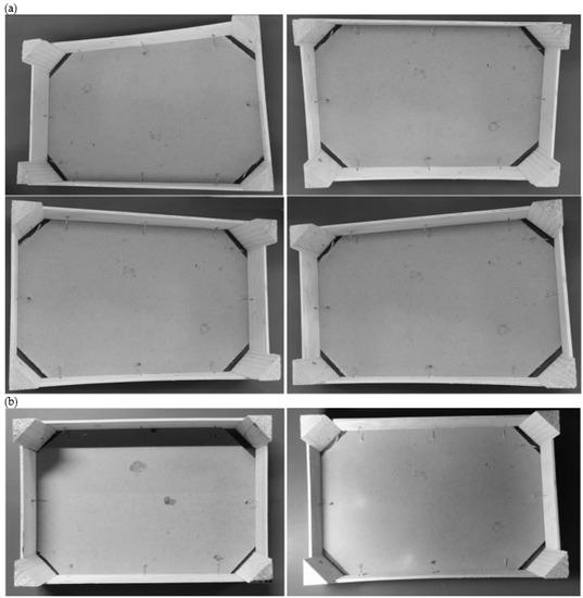
Figure 8.
Images were captured under different conditions to test the robustness of the badly stapled nails classification method using CNN. (a) Crate images are captured under a different angle of view than the one used to train the CNN. (b) Lighting conditions change, and shadows appear. Also, crate illumination is not uniform.
For using the Alexnet model, ROIs, where nails are in the crate, are defined previously. Classification results are shown in Table 2. As before, better performance is computed with the Alexnet model with predefined ROIs in the image. With no predefined ROIs, the SSD MobileNet model obtains better performance with both well and poorly stapled nails.
The second experiment, conducted to test the robustness of the classifier, changes the illumination conditions. The scene’s lighting changes generate shadows and changes in the crate illumination. Figure 8b shows two samples, one with changes in the illumination crate using direct lighting and the other with shadows in the crate using lateral lighting. One hundred images with each illumination are used to compare the results. Results are shown in Table 2. As before, the Alexnet and MobileNet models obtain better performance.
To compare the results of Alexnet and MobileNet models in a graph when image acquisition conditions change, Figure 9 shows a bar graph of the confidence matrix elements. Best performance is computed when the angle of view and lighting conditions are similar to the training step.
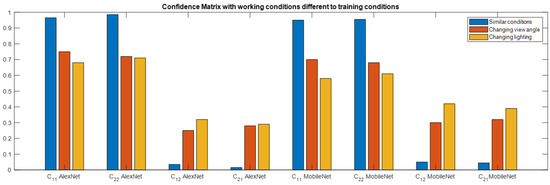
Figure 9.
Bar graphic of the confidence matrix elements to compare the results of Alexnet and MobileNet models in a graph when image acquisition conditions change. Best performance is computed when the angle of view and lighting conditions are similar to the training step.
4. Discussion
The detection of poorly nailed nails in a continuous production system of stitched crates is a very complex task that can easily be solved with a computer vision system. The prototype and fine-tuning of the quality inspection system were constructed in the Automatic Control and Industrial Informatics Institute laboratories in Valencia (Spain). The experiments were focused on a comparative analysis of the performance of five state-of-the-art classification algorithms based on a deep neural network and also, traditional computer vision methods. Several camera and light source positions were tested to obtain the robustness of the classification method under changes in the acquired image. The best performance configuration of lighting was obtained with indirect lighting. The camera location of the best performance obtained for the inspection system acquired images similar to the one shown in Figure 2. This work constitutes a benchmark to guide deep learning computer vision in realistic future applications.
Accuracy could rise by over 95% depending on the chosen classification model. This accuracy is obtained when the ROIs, where nails are in the image, are predefined and when using the AlexNet model. Since this is an inline inspection system, images of stitched crates can be triggered with a sensor that guarantees that the nail’s location in images is similar. Moreover, computing time using predefined ROIs is faster. On the contrary, this method needs human intervention to define the ROIs in the inspection system when the crates’ formats change.
If a complete autonomous inspection system is desired with no human intervention, the classification success is not over 95%, and computing time is increased. In this case, the inspection rate could arrive at 27 stitched crates per minute with the computing unit used in the experiments and the MobileNet model.
From the point of view of changing the image acquisition conditions, the classification rates deteriorate, and the best performance is computed if acquisition conditions are similar in training and working steps.
Currently, the proposed inspection system is a step forward in the field of stitched crates inspection that will help in any application where the detection of poorly nailed nails represents a crucial step.
5. Conclusions
The conclusions of using computer vision to detect badly stapled nails are:
- -
- Traditional computer vision techniques based on structured lighting do not solve the problem of badly stapled nail detection.
- -
- Novel neural network architectures allow to detection of badly stapled nails efficiently.
- -
- The AlexNet architecture achieves an accuracy of over the 96% if ROIs with nail presence are predefined in the image.
- -
- The MobileNet model accuracy is 95% with no predefined ROIs with nail presence.
- -
- The computing time of the MobileNet with no predefined ROIs is twice the computing time of the AlexNet model.
- -
- Reducing the area of the image with ROIs where nails are present improves the accuracy and reduces the computing time.
- -
- Indirect lighting allows an image free of shadows and brightness to be acquired.
- -
- The system can work with up to 60 crates per minute using the AlexNet model.
- -
- Neural networks represent a step ahead in resolving many industrial applications that could not be solved with traditional computer vision algorithms.
Author Contributions
Conceptualization, C.R.-V.; methodology, C.R.-V.; software, C.B.; validation, C.R.-V., A.C. and C.B.; formal analysis, C.R.-V. and C.B.; investigation, C.R.-V., A.C. and C.B.; resources, C.R.-V., A.C. and C.B.; data curation, C.B.; writing—original draft preparation, C.R.-V.; writing—review and editing, C.R.-V., A.C. and C.B.; visualization, C.R.-V.; supervision, C.R.-V.; project administration, C.R.-V.; funding acquisition, C.R.-V. All authors have read and agreed to the published version of the manuscript.
Funding
The Universitat Politècnica de Valencia has financed this project with project number 20200676 (Microinspección de superficies).
Institutional Review Board Statement
Not applicable.
Informed Consent Statement
Not applicable.
Data Availability Statement
Not applicable.
Acknowledgments
Thanks to the NVidia GPU grant program for its support in providing GPU for free.
Conflicts of Interest
The authors declare no conflict of interest.
References
- Parfitt, J.; Barthel, M.; Macnaughton, S. Food Waste within Food Supply Chains: Quantification and Potential for Change to 2050. Philos. Trans. R. Soc. B Biol. Sci. 2010, 365, 3065–3081. [Google Scholar] [CrossRef]
- Wasala, W.M.C.B.; Dharmasena, D.A.N.; Dissanayake, T.M.R.; Thilakarathne, B.M.K.S. Vibration Simulation Testing of Banana Bulk Transport Packaging Systems. Trop. Agric. Res. 2015, 26, 355. [Google Scholar] [CrossRef]
- Porat, R.; Lichter, A.; Terry, L.A.; Harker, R.; Buzby, J. Postharvest Losses of Fruit and Vegetables during Retail and Consumers’ Homes: Quantifications, Causes, and Means of Prevention. Postharvest Biol. Technol. 2018, 139, 135–149. [Google Scholar] [CrossRef]
- Lepine, J.; Rouillard, V.; Sek, M. On the Use of Machine Learning to Detect Shocks in Road Vehicle Vibration Signals. Packag. Technol. Sci. 2017, 30, 387–398. [Google Scholar] [CrossRef]
- Verghese, K.; Lewis, H.; Lockrey, S.; Williams, H. Packaging’s Role in Minimizing Food Loss and Waste Across the Supply Chain. Packag. Technol. Sci. 2015, 28, 603–620. [Google Scholar] [CrossRef]
- Grönman, K.; Soukka, R.; Järvi-Kääriäinen, T.; Katajajuuri, J.-M.; Kuisma, M.; Koivupuro, H.-K.; Ollila, M.; Pitkänen, M.; Miettinen, O.; Silvenius, F.; et al. Framework for Sustainable Food Packaging Design. Packag. Technol. Sci. 2013, 26, 187–200. [Google Scholar] [CrossRef]
- Valdés, A.; Ramos, M.; Beltrán, A.; Jiménez, A.; Garrigós, M. State of the Art of Antimicrobial Edible Coatings for Food Packaging Applications. Coatings 2017, 7, 56. [Google Scholar] [CrossRef]
- See, J.E.; Drury, C.G.; Speed, A.; Williams, A.; Khalandi, N. The Role of Visual Inspection in the 21st Century. Proc. Hum. Factors Ergon. Soc. Annu. Meet. 2017, 61, 262–266. [Google Scholar] [CrossRef]
- Ji, S.; Xu, W.; Yang, M.; Yu, K. 3D Convolutional Neural Networks for Human Action Recognition. IEEE Trans. Pattern Anal. Mach. Intell. 2013, 35, 221–231. [Google Scholar] [CrossRef]
- Shelhamer, E.; Long, J.; Darrell, T. Fully Convolutional Networks for Semantic Segmentation. IEEE Trans. Pattern Anal. Mach. Intell. 2017, 39, 640–651. [Google Scholar] [CrossRef]
- Basu, J.K.; Bhattacharyya, D.; Kim, T. Use of Artificial Neural Network in Pattern Recognition. Int. J. Softw. Eng. Its Appl. 2010, 4. [Google Scholar]
- Werbos, P.J. Links Between Artificial Neural Networks (ANN) and Statistical Pattern Recognition. In Machine Intelligence and Pattern Recognition; Elsevier: Amsterdam, The Netherlands, 1991; pp. 11–31. [Google Scholar]
- Funahashi, K.; Nakamura, Y. Approximation of Dynamical Systems by Continuous Time Recurrent Neural Networks. Neural Netw. 1993, 6, 801–806. [Google Scholar] [CrossRef]
- Abiodun, O.I.; Jantan, A.; Omolara, A.E.; Dada, K.V.; Mohamed, N.A.; Arshad, H. State-of-the-Art in Artificial Neural Network Applications: A Survey. Heliyon 2018, 4, e00938. [Google Scholar] [CrossRef]
- Antunes, A.; Laflaquiere, A.; Cangelosi, A. Solving Bidirectional Tasks Using MTRNN. In Proceedings of the 2018 Joint IEEE 8th International Conference on Development and Learning and Epigenetic Robotics (ICDL-EpiRob), Tokyo, Japan, 17–20 September 2018; pp. 19–25. [Google Scholar]
- Di Nuovo, A.; De La Cruz, V.M.; Cangelosi, A. A Deep Learning Neural Network for Number Cognition: A Bi-Cultural Study with the ICub. In Proceedings of the 2015 Joint IEEE International Conference on Development and Learning and Epigenetic Robotics (ICDL-EpiRob), Providence, RI, USA, 13–16 August 2015; pp. 320–325. [Google Scholar]
- Sigaud, O.; Droniou, A. Towards Deep Developmental Learning. IEEE Trans. Cogn. Dev. Syst. 2016, 8, 99–114. [Google Scholar] [CrossRef]
- Zorzi, M.; Testolin, A.; Stoianov, I.P. Modeling Language and Cognition with Deep Unsupervised Learning: A Tutorial Overview. Front. Psychol. 2013, 4, 515. [Google Scholar] [CrossRef]
- Salvaris, M.; Dean, D.; Tok, W.H. Deep Learning with Azure; Apress: Berkeley, CA, USA, 2018; ISBN 978-1-4842-3678-9. [Google Scholar]
- Davies, S.; Lucas, A.; Ricolfe-Viala, C.; Di Nuovo, A. A Database for Learning Numbers by Visual Finger Recognition in Developmental Neuro-Robotics. Front. Neurorobot. 2021, 15, 619504. [Google Scholar] [CrossRef] [PubMed]
- Krizhevsky, A.; Sutskever, I.; Hinton, G.E. ImageNet Classification with Deep Convolutional Neural Networks. Commun. ACM 2017, 60, 84–90. [Google Scholar] [CrossRef]
- Sandler, M.; Howard, A.; Zhu, M.; Zhmoginov, A.; Chen, L.-C. MobileNetV2: Inverted Residuals and Linear Bottlenecks. Comput. Vis. Pattern Recognit. 2018, 1–14. [Google Scholar]
- He, K.; Zhang, X.; Ren, S.; Sun, J. Deep Residual Learning for Image Recognition. In Proceedings of the 2016 IEEE Conference on Computer Vision and Pattern Recognition (CVPR), Las Vegas, NV, USA, 27–30 June 2016; pp. 770–778. [Google Scholar]
- Szegedy, C.; Vanhoucke, V.; Ioffe, S.; Shlens, J.; Wojna, Z. Rethinking the Inception Architecture for Computer Vision. In Proceedings of the 2016 IEEE Conference on Computer Vision and Pattern Recognition (CVPR), Las Vegas, NV, USA, 27–30 June 2016; pp. 2818–2826. [Google Scholar]
- Qin, X.; He, S.; Zhang, Z.; Dehghan, M.; Jagersand, M. ByLabel: A Boundary Based Semi-Automatic Image Annotation Tool. In Proceedings of the 2018 IEEE Winter Conference on Applications of Computer Vision (WACV), Lake Tahoe, NV, USA, 12–15 March 2018; pp. 1804–1813. [Google Scholar]
- Canziani, A.; Paszke, A.; Culurciello, E. An Analysis of Deep Neural Network Models for Practical Applications. Comput. Vis. Pattern Recognit. 2016, 1–7. [Google Scholar]
- Kang, B.; Tripathi, S.; Nguyen, T.Q. Real-Time Sign Language Fingerspelling Recognition Using Convolutional Neural Networks from Depth Map. In Proceedings of the 2015 3rd IAPR Asian Conference on Pattern Recognition (ACPR), Kuala Lumpur, Malaysia, 3–6 November 2015; pp. 136–140. [Google Scholar]
- Khan, A.; Sohail, A.; Zahoora, U.; Qureshi, A.S. A Survey of the Recent Architectures of Deep Convolutional Neural Networks. Artif. Intell. Rev. 2020, 53, 5455–5516. [Google Scholar] [CrossRef]
- Chen, L.; Liu, H.; Mo, J.; Zhang, D.; Yang, J.; Lin, F.; Zheng, Z.; Jia, R. Cross Channel Aggregation Similarity Network for Salient Object Detection. Int. J. Mach. Learn. Cybern. 2022, 13, 2153–2169. [Google Scholar] [CrossRef]
- Zhang, D.; Zheng, Z.; Li, M.; Liu, R. CSART: Channel and Spatial Attention-Guided Residual Learning for Real-Time Object Tracking. Neurocomputing 2021, 436, 260–272. [Google Scholar] [CrossRef]
- Razavian, A.S.; Azizpour, H.; Sullivan, J.; Carlsson, S. CNN Features Off-the-Shelf: An Astounding Baseline for Recognition. In Proceedings of the 2014 IEEE Conference on Computer Vision and Pattern Recognition Workshops, Columbus, OH, USA, 23–28 June 2014; pp. 512–519. [Google Scholar]
- Weiss, K.; Khoshgoftaar, T.M.; Wang, D. A Survey of Transfer Learning. J. Big Data 2016, 3, 9. [Google Scholar] [CrossRef]
- Geiger, A.; Lenz, P.; Urtasun, R. Are We Ready for Autonomous Driving? The KITTI Vision Benchmark Suite. In Proceedings of the 2012 IEEE Conference on Computer Vision and Pattern Recognition, Providence, RI, USA, 16–21 June 2012; pp. 3354–3361. [Google Scholar]
- Krasin, I.; Duerig, T.; Alldrin, N.; Ferrari, V.; Abu-El-Haija, S.; Kuznetsova, A.; Rom, H.; Uijlings, J.; Popov, S.; Veit, A.; et al. Openimages: A Public Dataset for Large-Scale Multi-Label and Multi-Class Image Classification. Available online: https://github.com/openimages (accessed on 15 November 2022).
- Parkhi, O.M.; Vedaldi, A.; Zisserman, A.; Jawahar, C.V. Cats and Dogs. In Proceedings of the 2012 IEEE Conference on Computer Vision and Pattern Recognition, Providence, RI, USA, 16–21 June 2012; pp. 3498–3505. [Google Scholar]
- Ricolfe-Viala, C.; Blanes, C. Improving Robot Perception Skills Using a Fast Image-Labelling Method with Minimal Human Intervention. Appl. Sci. 2022, 12, 1557. [Google Scholar] [CrossRef]
- Ren, S.; He, K.; Girshick, R.; Sun, J. Faster R-CNN: Towards Real-Time Object Detection with Region Proposal Networks. Comput. Vis. Pattern Recognit. 2015, 1–14. [Google Scholar] [CrossRef]
- Liu, W.; Anguelov, D.; Erhan, D.; Szegedy, C.; Reed, S.; Fu, C.-Y.; Berg, A.C. SSD: Single Shot MultiBox Detector. In European Conference on Computer Vision; Springer: Berlin/Heidelberg, Germany, 2016; pp. 21–37. [Google Scholar]


Disclaimer/Publisher’s Note: The statements, opinions and data contained in all publications are solely those of the individual author(s) and contributor(s) and not of MDPI and/or the editor(s). MDPI and/or the editor(s) disclaim responsibility for any injury to people or property resulting from any ideas, methods, instructions or products referred to in the content. |
© 2023 by the authors. Licensee MDPI, Basel, Switzerland. This article is an open access article distributed under the terms and conditions of the Creative Commons Attribution (CC BY) license (https://creativecommons.org/licenses/by/4.0/).