Article

Research on the Design and Gait Planning of a Hexapod Robot Based on Improved Triangular Gait for Lunar Exploration

1
College of Mechanical and Electronic Engineering, Nanjing Forestry University, Nanjing 210037, China
2
China-Pakistan Belt and Road Joint Laboratory on Smart Disaster Prevention of Major Infrastructures, Southeast University, Nanjing 210096, China
*
Author to whom correspondence should be addressed.
Appl. Sci. 2024, 14(1), 260; https://doi.org/10.3390/app14010260
Submission received: 30 November 2023 / Revised: 23 December 2023 / Accepted: 25 December 2023 / Published: 27 December 2023

Abstract

:
To address the challenges posed by the loose lunar surface structure, including the adhesive nature of lunar soil, strong corrosiveness and the slow walking speed of robots using traditional tripod gaits, this paper proposes the design of a small lunar exploration hexapod robot with hollow legs, employing anti-corrosive aerospace materials throughout. Additionally, an inverted gait motion mode is introduced. Simulation analysis is conducted on the displacement, angular velocity, angular acceleration and joint torque of the robot’s body under both traditional tripod gaits and the “inverted gait” motion mode. A physical prototype of the robot is developed to validate the rationality of its structure. Our research results indicate that the designed lunar exploration hexapod robot’s body structure is reasonable, enabling it to stand and walk normally on the unstructured lunar terrain. The hollow design reduces the adhesion of lunar soil. The inverted gait motion mode expands the effective swinging range of the robot’s legs and increases the effective step length during leg swing. Additionally, it improves the robot’s movement speed, eliminates vibrations at the joints during motion and improves the robot’s stability during the support phase.

1. Introduction

With the development of science and technology, many countries and space agencies are committed to space exploration, and the Moon is also proposed to be used as a gateway and entry point for future human space missions. Scientists have come up with the concept of building infrastructure on the Moon, such as a moon base [1,2,3]. Therefore, the exploration of the Moon is very important for the above tasks. According to sources, the surface of the Moon is covered with a layer of loose rock fragments, often referred to as lunar regolith [4]. Through the analysis of lunar soil samples, it can be seen that most of the regolith layer is composed of particles with a size of less than 1 cm, which can be subdivided into three categories: dust (<50 μm), soil (<1 mm) and coarse fine (1–10 mm), which are very loose due to long-term weathering, so the lunar soil is very soft, the overall hardness is low and it has strong adsorption [5,6,7]. In addition, the Moon’s surface is riddled with craters of various sizes, ranging in diameter from a few microns to hundreds of kilometers, with most moon craters being circular or elliptical, with larger diameters and lower depths, and often with complex topographic features [8,9,10]. In the face of loose lunar soil, craters and craters on the Moon, as well as low-pressure, low-temperature and oxygen-deficient environments in space, it is very difficult and expensive to carry out exploration missions on the Moon [11].
Robots have great potential to achieve planetary exploration missions, which can help people explore a wide variety of unknown environments and protect their lives. So far, most of the robots that have successfully carried out cosmic exploration missions have been wheeled robots; however, several experiments have proven that wheeled robots accumulate a large amount of substrate material in their tire portion as they move forward, thus generating a high compaction resistance and making it difficult to avoid obstacles in complex environments [12,13]. Since most of the legged robots are designed with biomechanical principles, they are flexible, efficient and highly adaptable, and they have very good maneuverability to traverse complex environments, making them more suitable for exploring unstructured terrain [14,15].
The development of legged robots can be traced back as far as the mid-20th century, and with the continuous research of scientists, legged robots have made significant progress in different fields [16]. Among many legged robots, hexapods have great research value in planet exploration due to their better stability and gait diversity [17]. In the 1980s, Carnegie Mellon University in the United States developed a series of robots for planet exploration, such as Ambler and Dante II [18,19]. Each of the Ambler robot’s legs is a right-angled coordinate leg, with the help of a rack and pinion inside the leg to adjust the vertical position of the body to cross the obstacles. Subsequently, Carnegie Mellon University developed the hexapod robot Dante II in the early nineties of the twentieth century to meet the needs of the exploration of large slopes and steep terrain on the surface of the planet and conducted experiments on active volcanoes. Each leg can independently adjust its vertical height to adapt to the rough terrain and use ropes for traction so that it can climb up and down the cliff face. In recent years, Chiba University in Japan has developed a large-scale hexapod robot, COMET-4, driven by hydraulic cylinders [20], with a fuselage weight of 2120 kg and a load capacity of 40 kg. Each leg has four degrees of freedom, and the leg joints are driven by hydraulic cylinders. The forward and backward swing of the base joints is driven by hydraulic motors, which have better driving ability. With the whole machine updated and tuned, the walking speed can approach 1 km/h. It has the capacity to traverse vertical obstacles up to 1 m in height and the ability to overcome a 20° slope resistance. Beijing Aeronautical University and the Technical University of Milan in Italy have cooperated to develop two generations of NOROS legged robots with driving wheels assembled at the knee joints, which can switch between wheels and legs by converting the attitude of the robot. The robot legs are 0.6 m long, evenly distributed along the circular body. Each leg has four degrees of freedom, and each joint is driven by a DC motor. The body of the robot adopts a modularized structure and is equipped with control and drive system hardware and cameras. However, the above-mentioned legged robots are generally large and require a large amount of energy supply, which is not convenient for exploring the unstructured environment of the Moon. In addition, most of the robots are arranged with rectangular legs in the overall structural layout, with a high degree of overlap in the swinging range of the legs, which may cause structural interference and collisions and affect the robot’s moving speed during movement. At the same time, due to the complex, unstructured terrain of the lunar surface, lunar soil is highly adsorbent and corrosive, which is prone to corroding the above robots and affecting their service lives.
In order to solve the above problems, this paper designs a small hexapod robot for lunar exploration. The legs of the robot were hollowed out according to the special terrain environment of the Moon and the strong adsorption of lunar soil, which reduces the contact area with lunar soil as much as possible under the premise of ensuring the structural stability and load capacity of the robot and prolonging the service life of the robot while reducing its overall weight. To solve the problem of slow movement of the robot and shaking of the joints when walking, this paper proposes an “inverted gait” mode based on the traditional triangular gait and makes a comparative simulation analysis with the traditional straight gait. The results show that the mode reduces the redundant movements of the robot when it starts, effectively improves the movement speed of the robot when it travels straight and eliminates the jitter generated at the joints when the robot moves. Finally, through a prototype experiment, it can be concluded that the overall structure of the robot is reasonable and can satisfy the robot’s walking task in unstructured terrain.

2. Design of the Lunar Exploration Hexapod Robot

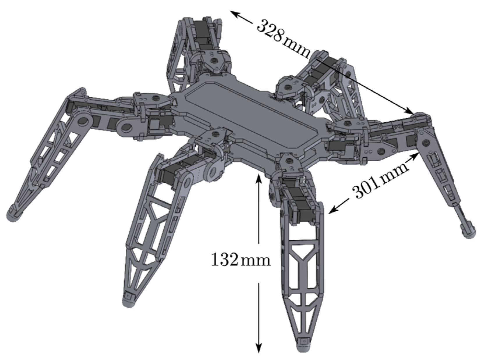
2.1. Overall Scheme Design

The Moon is in a low-temperature, hypoxia, low-pressure, low-gravity environment, and lunar soil has high adsorption that makes it easy to corrode materials, so it has the requirements of light weight, high performance and corrosion resistance for the lunar exploration robot. Therefore, the robot body material needs to have excellent comprehensive properties such as low density, high specific stiffness, low expansion and high thermal conductivity. Traditional lightweight structural materials such as aluminum alloys and titanium alloys are difficult to fully meet the above requirements, while SiCP/Al composites have excellent comprehensive properties such as low density, high specific stiffness, low expansion and corrosion resistance, which are widely used in the aerospace field [21,22,23]. Comprehensively speaking, the robot in this paper is selected as a whole SiCp/Al composite material, and its performance parameters are shown in Table 1.
As shown in Figure 1, the overall dimensions of the lunar exploration hexapod robot’s design are 301 mm × 324 mm × 132 mm, with a mass of 10 kg. The structural design prototype of the lunar exploration hexapod robot is a hexapod insect in nature. The leg layout adopts an elliptical layout, which reduces the overall volume of the robot compared with the circular layout. Compared with the rectangular layout, the elliptical layout ensures that the robot legs will not collide while having a large swing space. As shown in Figure 2, the fan represents the range of movement that each leg can move, and L represents the maximum distance that a single leg can walk.
To reduce the overall weight of the robot while ensuring good load capacity, the leg structure of the robot is designed to mimic the joints of insect legs, including the coxa, femur and tibia. Adjacent segments are connected by adjacent joints to enable rotation, as illustrated in Figure 3. The robot’s drive system employs an STM32F407 control board and a 24-channel servo driver board, utilizing serial communication. The control of the 18 drive motors of the robot is achieved by outputting PWM signals. The motors used in this study are RDS3115 dual-axis digital servos, as depicted in Figure 4. The servos internally incorporate a microcontroller (MCU) for control, adjusting the angle through PWM pulse-width modulation with a rotation range of 0–180°. They exhibit the advantages of high control precision and good linearity, with specific parameters detailed in Table 2.

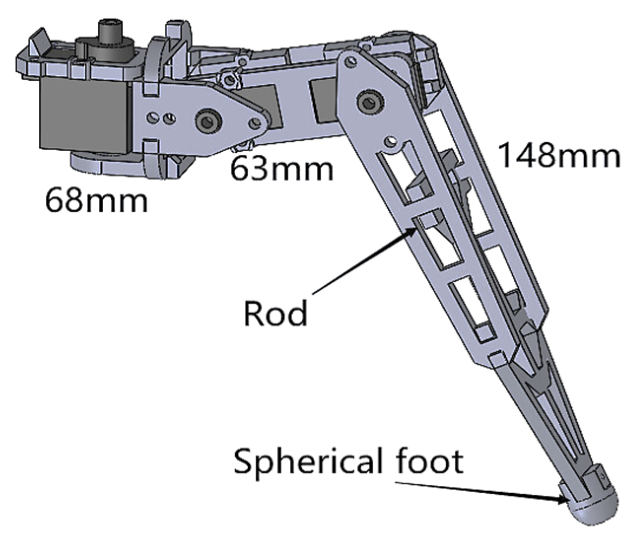
2.2. Structural Design of the Legs of the Lunar Exploration Hexapod Robot

The mechanical leg is an important part of the hexapod robot, and its leg structure needs to be able to ensure that the robot can walk flexibly on the Moon while having a good load-bearing capacity. In this paper, the robot legs are set up as hip, knee and ankle joints according to the leg structure of a hexapod insect; the hip joint provides the power of the robot to move forward, and the knee and ankle joints provide the power of the robot to move up and down. At the same time, the motors at the joints are connected in series with the robot’s leg linkage to ensure that the leg structure of the robot is compact and the rotation angle is larger in the three joints so that the leg can have a larger movement. In view of the strong adsorption of lunar soil, the mechanical leg of the lunar exploration hexapod robot was designed: There are holes on both sides of the mechanical leg fixed to the motors, which are rotated by the motors to drive the legs to move; the legs are fixed between the ankle joints and the foot ends by increasing the connecting rods. At the same time, the connecting rods adopt a skeletonized design so that the robot will shake off the sticky adhesion with its own vibration when it is walking. For the extreme, unstructured terrain of the lunar surface, the design of the robot’s foot end is also essential. George Lordos’ team has conducted a variety of comparative analyses of robotic feet suitable for extreme lunar terrain, including planar, spherical and planar–spherical hybrid designs. Under a 14 kg load, it is found that the planar foot ends will slip due to insufficient contact when in contact with rocks, lunar craters and other environments, while the spherical design has a better contact area and higher stability [24]. Therefore, in this paper, the foot end of the robot is designed as a spherical foot, which can effectively reduce the impact of the complex lunar environment on the robot’s walking. The specific mechanical leg structure is shown in Figure 5 (dimensions of 68 mm, 63 mm and 148 mm).

3. Kinematic Analysis of the Lunar Exploration Hexapod Robot

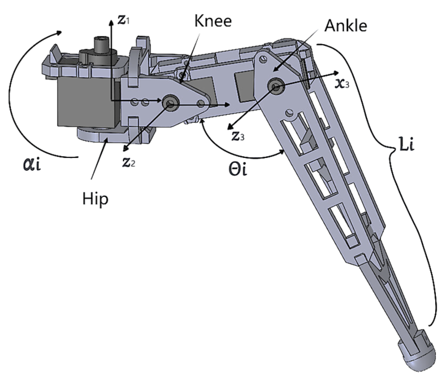
3.1. Analysis of the Spatial Position of the Robotic Legs of the Lunar Exploration Hexapod Robot

According to the D-H method, the coordinate system of each joint of the hexapod robot and the end of the robotic foot was established. The relative position between the hip joint, knee joint and ankle joint of the robot leg was obtained through the conversion between the coordinates, thereby obtaining the position of the end of the robot actuator. The D-H coordinate system of the leg of the hexapod robot is shown in Figure 6. The x-axis and the z-axis are specified at the center of the swing axis of each motion joint. The y-axis does not need to be specially specified because it is perpendicular to the x-axis and z-axis. Table 3 shows the D-H parameters of the robot leg. The fuselage coordinate system of the hexapod robot is x0z0, the hip coordinate system is x1z1, the knee coordinate system is x2z2 and the ankle coordinate system is x3z3 through the conversion between the coordinates. Since the hip joint and the other two rotational planes are perpendicular to each other, the corresponding coordinate system of the hip joint needs to be rotated α i around the x1 axis. The homogeneous transformation matrix between the coordinates of adjacent joints of the tandem joint robot is:
F = cos θ i sin θ i sin θ i α i 1 sin θ i cos α i 1 sin θ i sin α i 1 sin α i 1 d i sin θ i sin α i 1 cos θ i cos α i 1 cos α i 1 cos α i 1 d i 0 0 0 1

3.2. Forward and Reverse Kinematic Analysis of the Lunar Exploration Hexapod Robot

For a serial joint-type hexapod robot, forward kinematics aids in the analysis of the motion space of the hexapod robot. By substituting the D-H parameters from Table 3 into Equation (1), the D-H transformation matrix corresponding to each joint of the mechanical leg of the lunar hexapod robot can be obtained. Multiplying these transformation matrices yields the homogeneous transformation matrix between adjacent joint coordinates of the robot:
F = cos θ 1 cos ( θ 2 + θ 3 ) cos θ 1 sin ( θ 2 + θ 3 ) sin θ 1 cos θ 1 ( l 1 + l 2 cos θ 2 + l 3 cos ( θ 2 + θ 3 ) ) sin θ 1 cos ( θ 2 + θ 3 ) sin θ 1 sin ( θ 2 + θ 3 ) cos θ 1 sin θ 1 ( l 1 + l 2 cos θ 2 + l 3 cos ( θ 2 + θ 3 ) ) sin ( θ 2 + θ 3 ) cos ( θ 2 + θ 3 ) 0 l 2 sin θ 2 l 3 sin ( θ 2 + θ 3 ) 0 0 0 1
The respective coordinates of the robot’s foot end are:
X = ( cos θ 1 ) ( l 1 + l 2 cos θ 2 + l 3 cos ( θ 2 + θ 3 ) ) Y = ( sin θ 1 ) ( l 1 + l 2 cos θ 2 + l 3 cos ( θ 2 + θ 3 ) ) Z = l 2 sin θ 2 l 3 sin ( θ 2 + θ 3 )
The value of each joint can only be determined by the inverse kinematics solution. That is, the robot may attain the desired posture state by reversing the angle of each joint in its robotic leg so that it can achieve the desired posture state. The inverse kinematics solution of the robotic leg is solved from its forward kinematics model:
θ 1 = arctan sin θ 1 ( l 1 + l 2 cos θ 2 + l 3 cos ( θ 2 + θ 3 ) ) cos θ 1 ( l 1 + l 2 cos θ 2 + l 3 cos ( θ 2 + θ 3 ) )
θ 2 = arccos l 2 sin θ 2 + l 3 sin ( θ 2 + θ 3 ) ( l 3 cos θ 3 + l 2 ) 2 + ( l 3 sin θ 3 ) 2 + arcsin ( 1 ( l 3 cos θ 3 + l 2 ) 2 + ( l 3 sin θ 3 ) 2 )
θ 3 = arccos ( l 3 cos θ 3 + l 2 ) 2 + ( l 2 sin θ 2 + l 3 sin ( θ 2 + θ 3 ) ) 2 l 2 2 l 3 2 2 l 2 l 3

4. Motion Simulation and Experiment of the Lunar Exploration Hexapod Robot

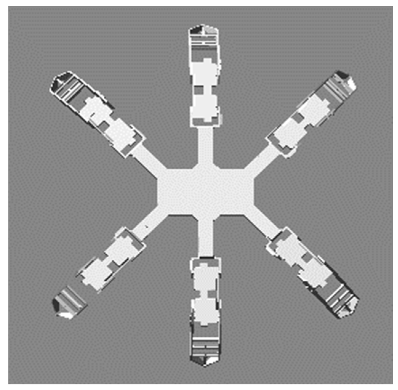
4.1. Establishment of a Robot Simulation Model

In this paper, a simplified model of the lunar exploration hexapod robot, as shown in Figure 7, is established using ADAMS2019 software without affecting the simulation results, and the simulation analysis is carried out.
In order to ensure the normal walking of the robot in the unstructured environment of the lunar environment, it is necessary to add relevant contact force parameters of the lunar surface onto the foot of the robot, such as the Coulomb friction, the static damping coefficient and the dynamic damping coefficient. The parameters are shown in Table 4 [25,26].

4.2. Kinematic Simulation Analysis of the Lunar Exploration Hexapod Robot

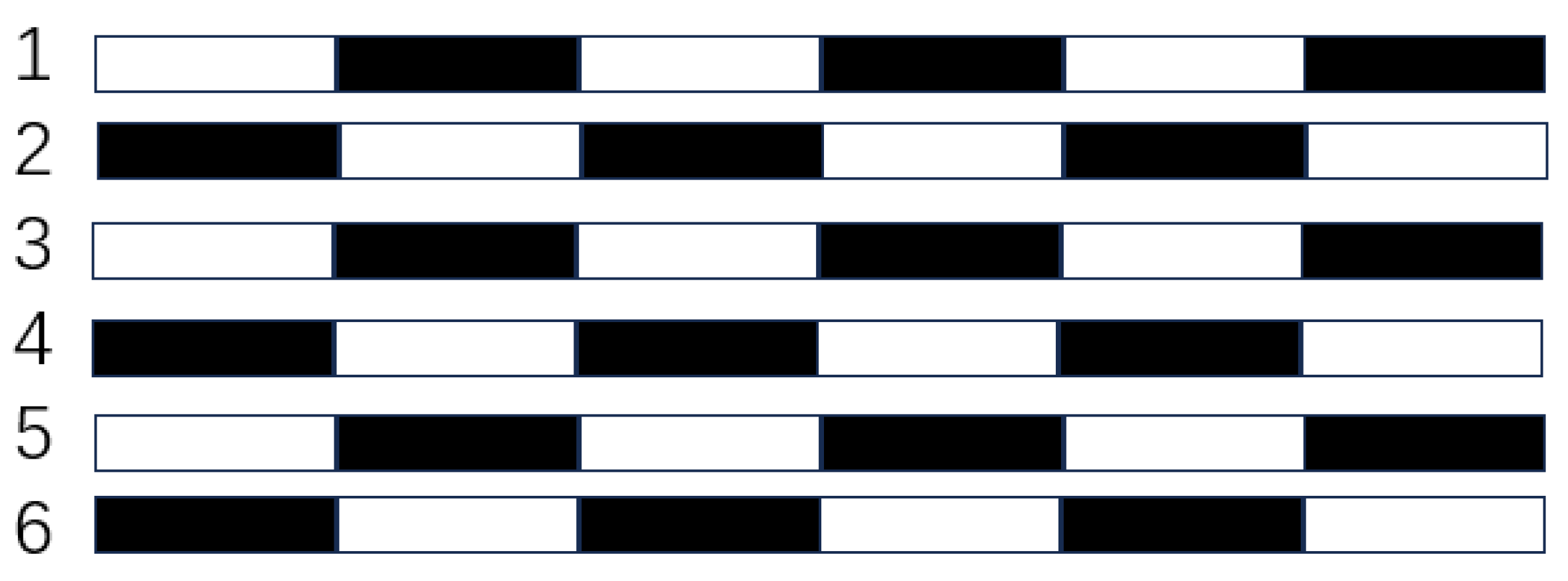
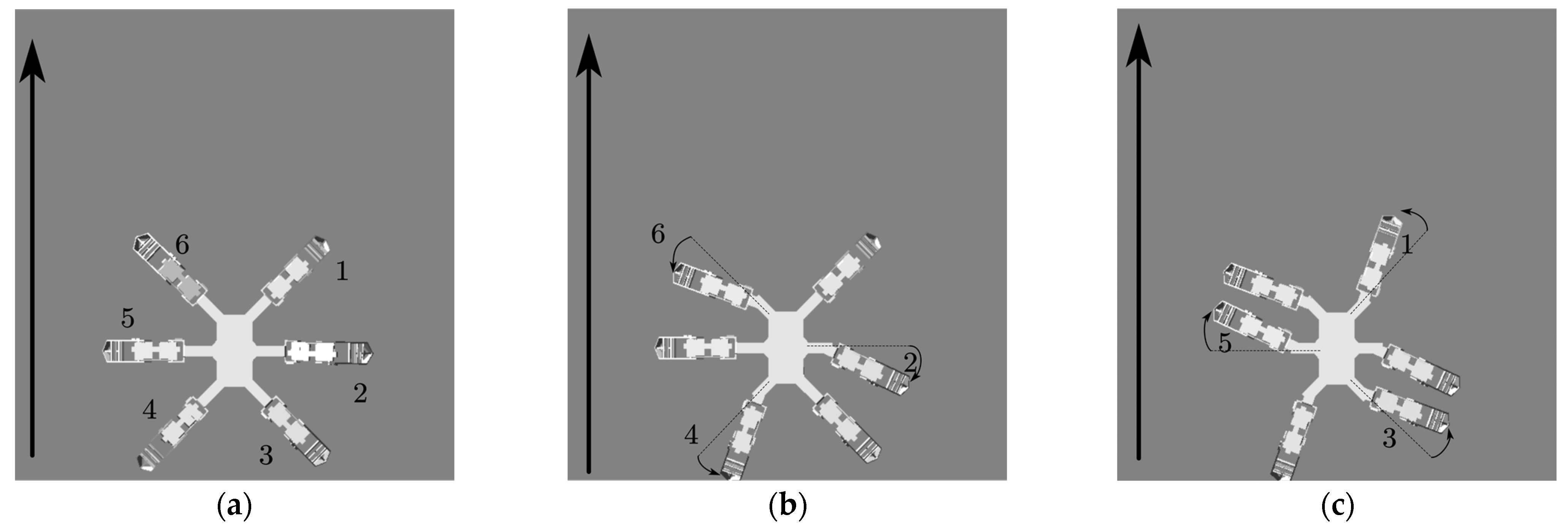
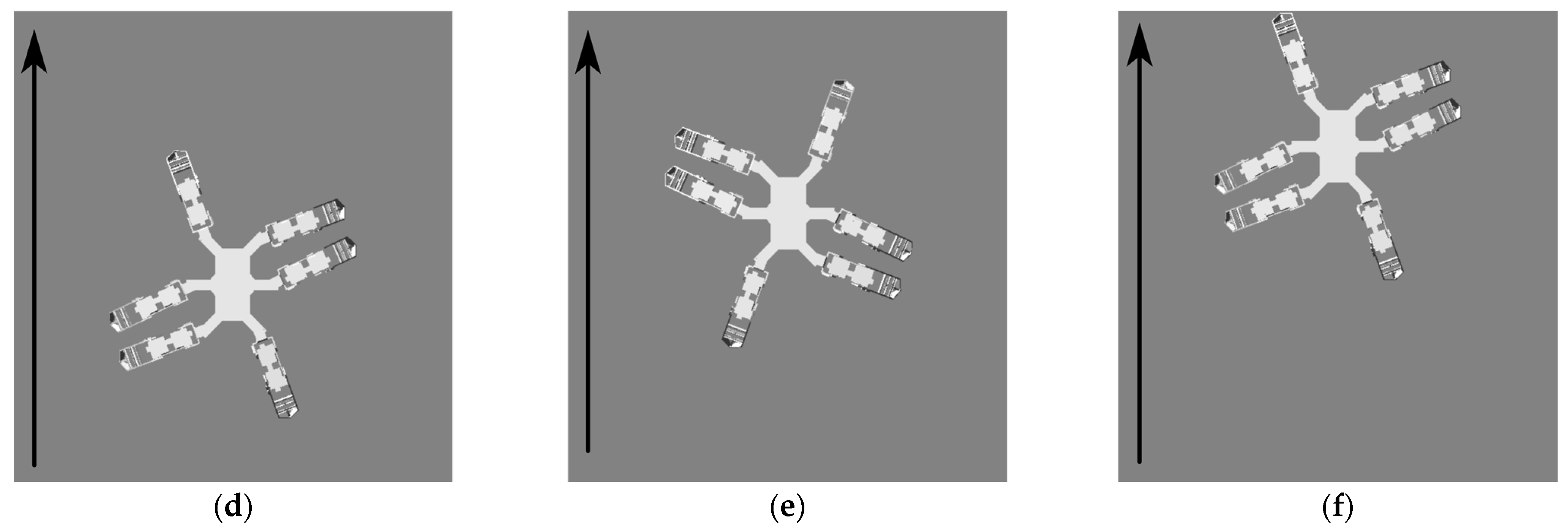
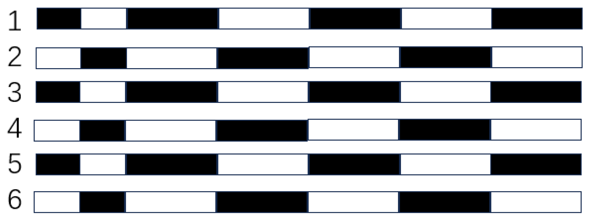
4.2.1. Straight Forward Gait and Inverted Gait Planning

The walking of the hexapod robot is a cyclical variation process, with each leg having two states: a swing phase and a support phase. The swing phase is the process where a single leg gradually lifts from the supporting state to the preset highest joint position and then gradually lands, completing the positional movement. Subsequently, the legs of the robot support the ground, and the swinging process of the hip joint is called the support phase [27,28,29]. The motion gait of the hexapod robot can be classified into tripod gait, quadruped gait, adaptive gait, etc., depending on the number of legs in the support phase. Among them, the tripod gait is the most common gait for hexapod robots. The legs are divided into two groups, and each group moves alternately to maintain the stability of the robot. The tripod gait can be optimized by adjusting gait parameters and changing step frequencies to adapt to different environmental conditions. The quadruped gait involves four legs supporting the robot during movement, offering higher stability and adaptability compared to the tripod gait but at a slower speed. Adaptive gait is primarily achieved by the robot’s own sensors obtaining environmental information and then adjusting the corresponding gait through the control system to adapt to different terrains, which involves relatively complex control [30,31,32].
This paper employs the tripod gait for simulating the straight-line motion of the lunar exploration hexapod robot. The traditional tripod gait is illustrated in Figure 8. Firstly, the six legs are numbered and divided into two groups, with legs 1, 3 and 5 forming the first group and legs 2, 4 and 6 forming the second group. The vertical arrows indicate the forward direction of the robot. At t = 0, all six legs support the robot, as shown in Figure 8a. Subsequently, the first group of legs lifts and swings forward within 1 s, while the second group of legs supports the robot, as shown in Figure 8b. After 1 s, the second group of legs lifts and swings forward, while the first group of legs supports the robot, and their hip joints swing backward, as shown in Figure 8c. Figure 8d–f illustrate the alternating movement of the two groups of legs during the robot’s forward motion. The robot’s straight-line motion is completed through the periodic cycle of these two movements. Figure 9 depicts the temporal changes in the states of the robot’s six legs, where white represents the swinging phase and black represents the supporting phase.
To address the issues of slow robot movement and joint tremors, this paper proposes an “inverted gait” motion mode based on the tripod gait, as shown in Figure 10. At t = 0, all six legs of the robot are supporting the ground, as illustrated in Figure 10a. Subsequently, within 0.5 s, the second group of legs lifts and swings slightly backward, while the first group of legs supports the robot. The robot presents an inverted starting posture, as shown in Figure 10b. Then, within 0.5–1 s, the first group of legs lifts and swings forward, while the second group of legs supports the robot, as shown in Figure 10c. Within 1–2 s, the second group of legs lifts and swings forward significantly, while the first group of legs supports the robot. The reverse swing of the hip joint provides forward propulsion for the robot, as shown in Figure 10d. The alternating movement of the two groups of legs, as demonstrated in Figure 10e,f, completes the robot’s forward motion. Figure 11 depicts the temporal changes in the states of the robot’s six legs in the inverted gait mode. Through comparison, it is found that in the inverted gait mode, due to the small backward swing of the second group of legs during startup, the robot presents an inverted posture, providing a larger swing range for the hip joint movement. This increases the effective step length of the robot during travel, reduces lateral offset and smoothens the subsequent alternating swing of the two sets of mechanical leg joints. This reduction in the time for the two sets of legs to individually swing in place during robot walking accelerates the robot’s movement speed.

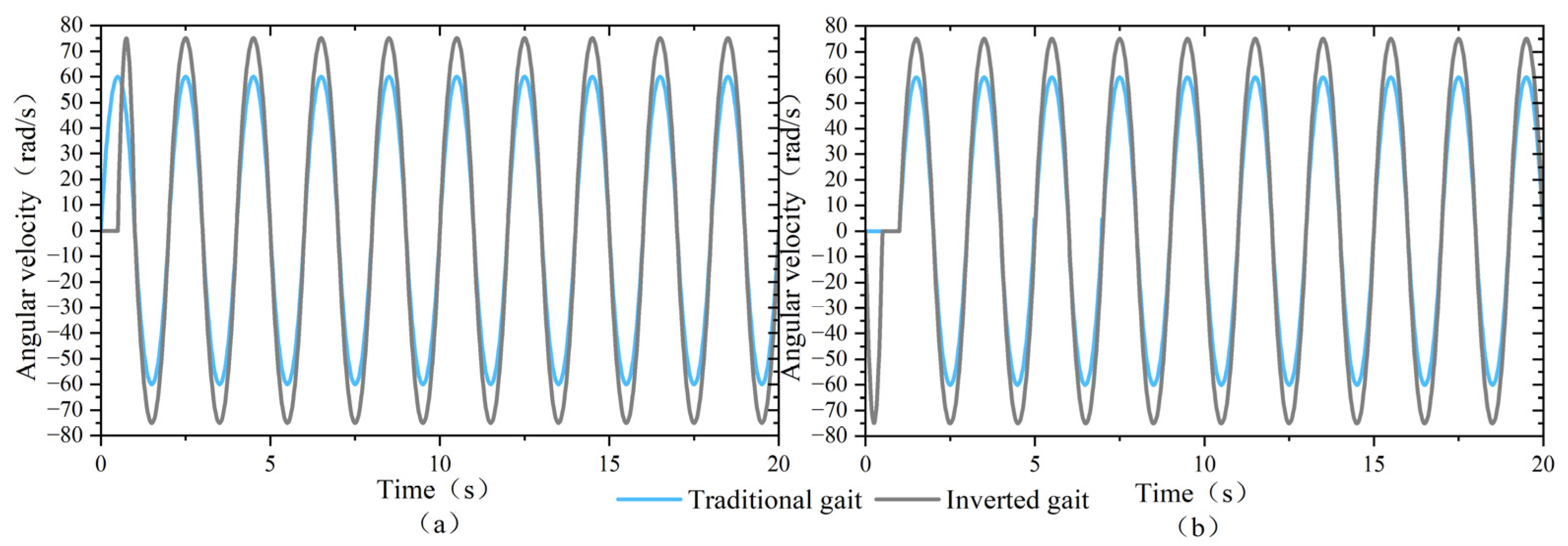
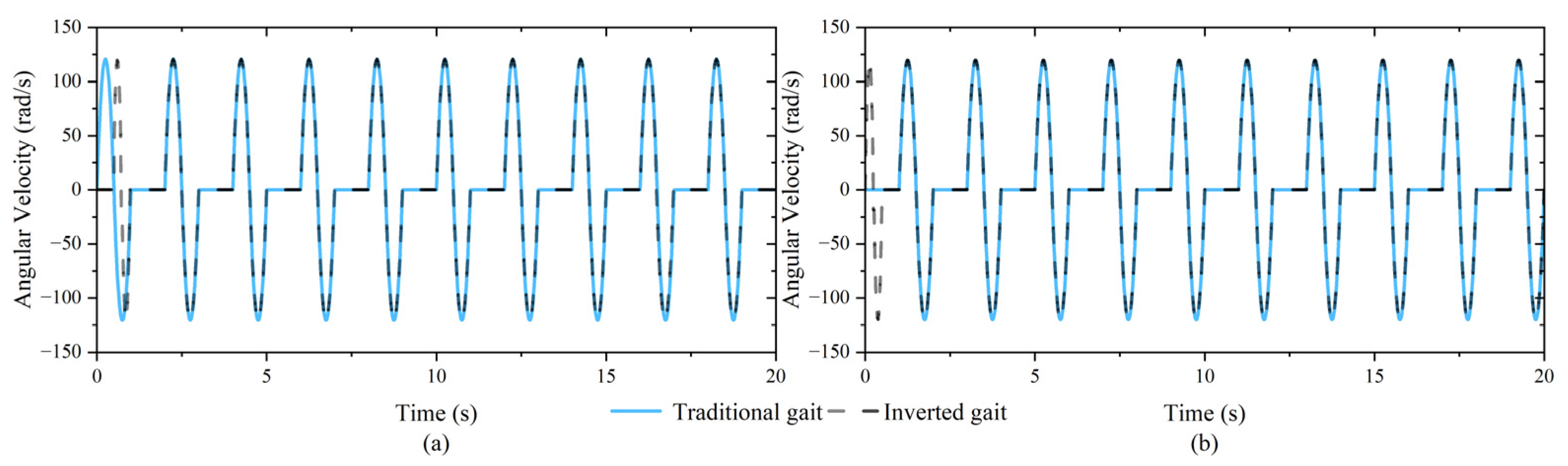
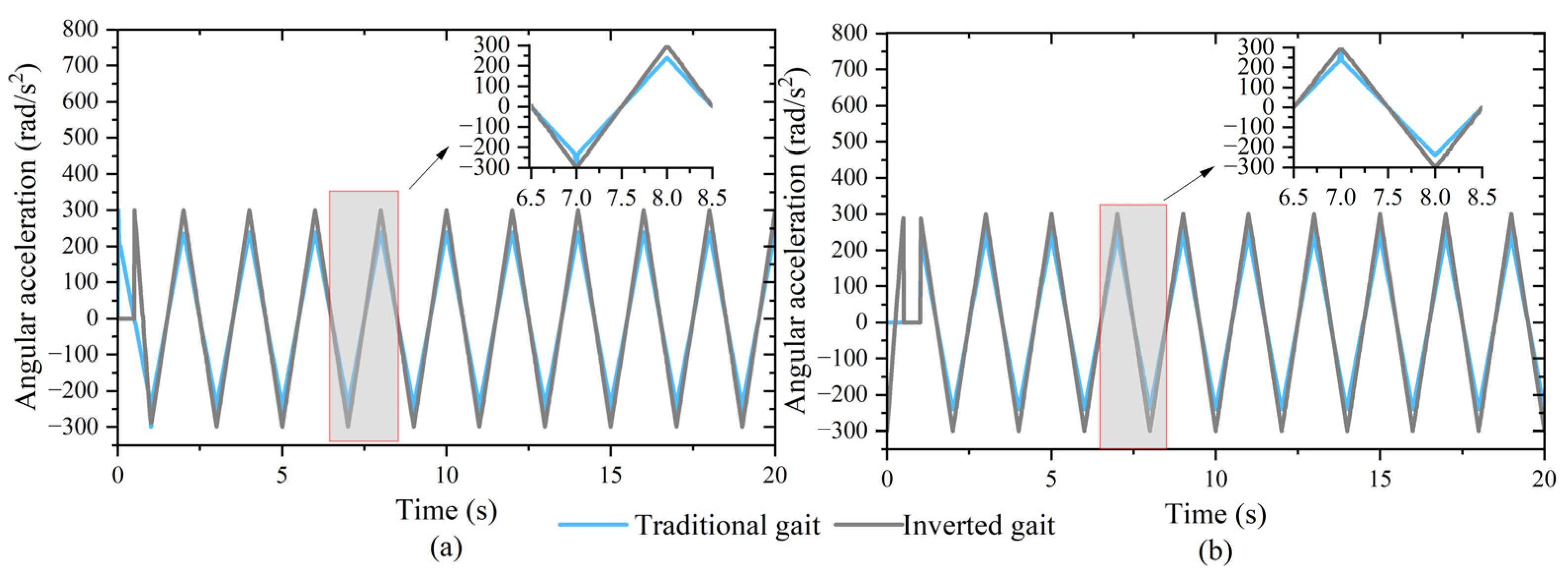
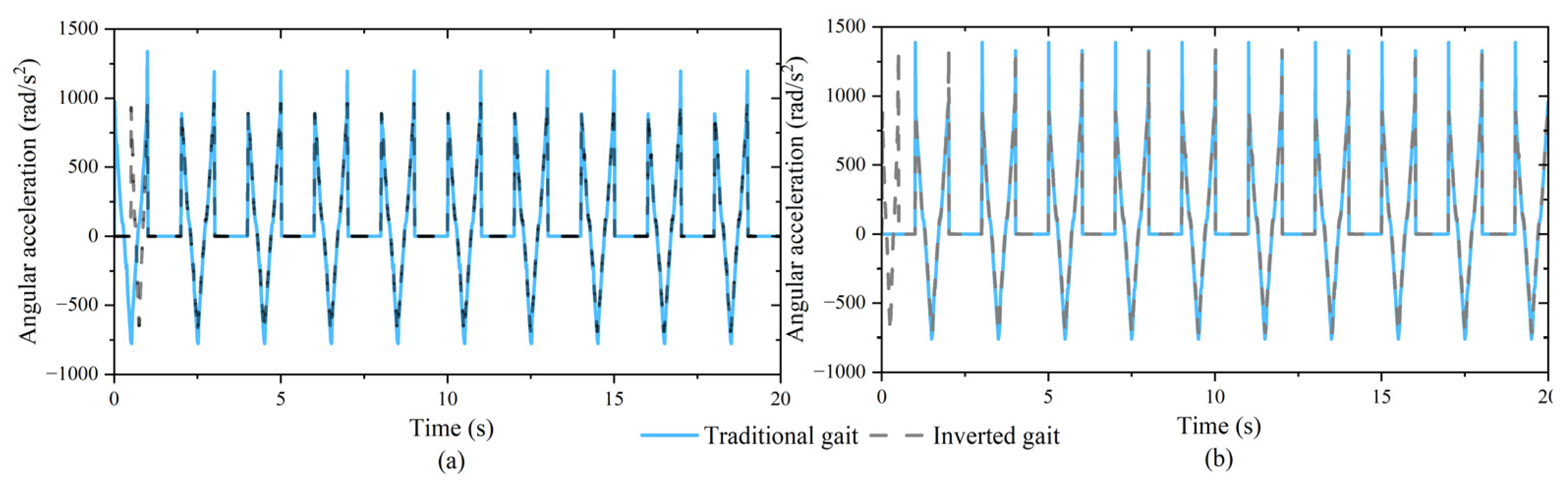
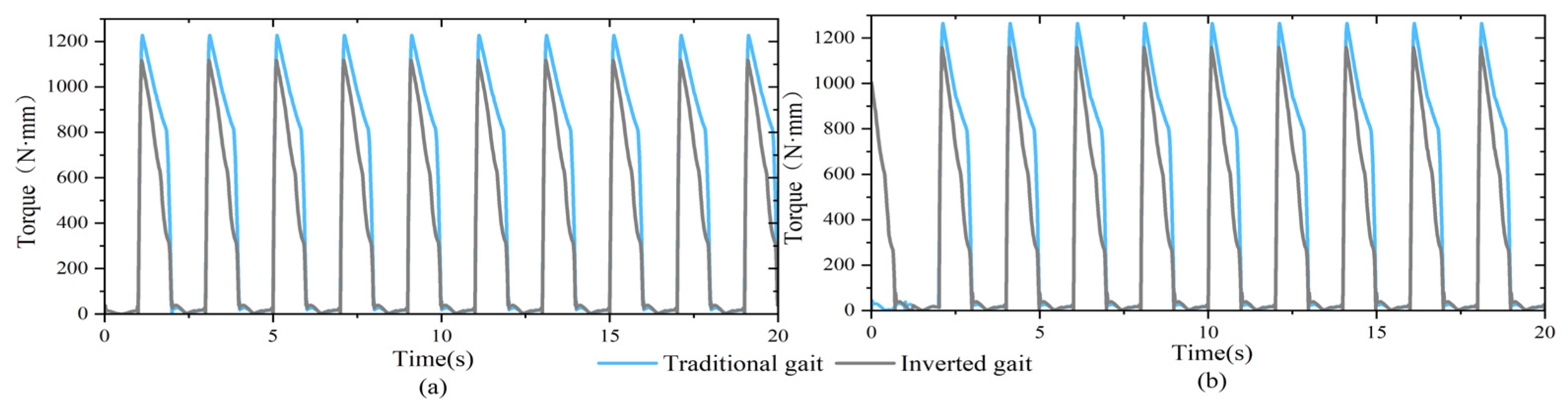
4.2.2. ADAMS Kinematic Simulation Analysis

Only adding the drive and contact cannot make the robot walk; it also needs to use the STEP function in ADAMS as the drive function. After adding all the drive functions as required, set the simulation parameters: End Time = 20, Steps = 50. After the simulation, the displacement curves of the robot’s centroid in the X, Y and Z directions are obtained, as shown in Figure 12. The center of the robot coincides with the displacement of its center of mass in the y-axis direction. In the same simulation time, the displacement of the robot along the y-axis direction in the traditional gait is 2235 mm, and in the inverted gait mode, the displacement is 2895 mm. The displacement distance is increased by 29.53%, indicating that the robot moves faster in the inverted gait. Figure 12b shows that the shift of the robot in the x-axis direction is less fluctuating than that of the traditional gait curve during the “inverted gait” movement. Figure 12c shows that the displacement of the robot in the z-axis direction in the inverted gait mode shows periodic up-and-down fluctuations compared with the traditional gait, and the fluctuation amplitude is smaller. According to the comparison of the two gait fuselages and their displacement curves in all directions, it can be found that the movement speed of the robot is increased by 29.53% in the inverted gait mode, the offset fluctuations in the left and right directions and up and down directions are smaller and the robot achieves faster and more stable movement in the same amount of time.
When the hexapod robot is moving, the angular velocity of the rotation of each joint of the robotic legs reflects the rate of the robot’s movement. Figure 13 and Figure 14 show the comparison curves of the angular velocities of the hip and knee joints of the two groups of legs in the two gait states. As can be seen from Figure 13 and Figure 14, the angular velocity of the hip and knee joints of the two groups of legs changes periodically. The maximum angular velocities of the hip and knee joints of the two groups of legs are, respectively, 60 rad/s and 120 rad/s in the traditional gait mode of the robot. In the inverted gait mode, the second group of legs swung backward within 0–0.5 s, causing the robot to assume an inverted starting posture, providing more space for the subsequent swinging motion of the robot’s hip joints. Consequently, the robot’s hip joints exhibited an increased swing amplitude during the swinging motion, resulting in a faster forward speed for the robot. The maximum angular velocity of the hip joints for both the first and second groups of mechanical legs was 75 rad/s. Compared to the traditional gait mode, the angular velocity increased by 25%. The maximum angular velocity of the knee joints for both the first and second groups of mechanical legs was 120 rad/s. It can be observed that in the “inverted gait” mode, by expanding the swing range of the robot’s legs and increasing the angular velocity of hip joint movement, the robot’s gait frequency and effective step length per step were improved, consequently enhancing the robot’s movement speed.
The change in angular acceleration of the hexapod robot can reflect the speed of the angular velocity change between the joints of the robot in the process of linear motion, and the stability of the robot in motion can be judged by analyzing it. Figure 15 and Figure 16 are the comparison curves of the angular acceleration of the hip and knee joints of the two groups of robotic legs in the two gaits. Through analysis, it was found that in both motion modes, the angular acceleration curves of the robot’s legs exhibited periodic variations. In the traditional gait, the maximum angular acceleration of the hip joints for both leg groups was 300 rad/s2, and the maximum angular acceleration of the knee joints for the first and second leg groups was 1195.73 rad/s2 and 1389.71 rad/s2, respectively. In the “inverted gait” motion mode, the maximum angular acceleration of the hip joints for both leg groups was 300 rad/s2, and the maximum angular acceleration of the knee joints for the first and second leg groups was 959.67 rad/s2 and 1334.61 rad/s2, respectively. Compared to the traditional gait, the maximum peak values of knee joint angular acceleration for both the first and second leg groups were reduced by 19.7% and 3.9%, respectively. Simultaneously, the analysis revealed that in the robot’s traditional gait motion, abrupt changes in signals during startup and leg phase transitions could lead to tremors, affecting the stability of the robot during operation. In contrast, the inverted gait provided an inverted body posture during startup, optimizing the robot’s dynamic model and offering greater swing space for the robot’s legs. The simultaneous swinging of both leg groups during motion resulted in a smoother transition of signals, making the transition between the swing and support phases more seamless. This eliminated tremors, enhancing the stability of the robot.
The magnitude of the torque of each joint in the process of linear motion of the hexapod robot is closely related to the bearing capacity of the torque of the motor shaft, which directly affects whether the robot can move normally. Figure 17 and Figure 18 are, respectively, the comparison curves of the robot’s hip and knee torques in the two gaits. Through analysis, it was found that in the traditional gait, the maximum torques of the hip joints of the first and second groups of legs were, respectively, 1228.06N·mm and 1265.28N·mm, and the maximum torques of the knee joints were, respectively, 1445.88 N·mm and 1288.36 N·mm. In the “inverted gait” mode, the maximum torques of the hip joints of the first and second groups of legs were, respectively, 1118.79 N·mm and 1159.45 N·mm, and the maximum torques of the knee joints were, respectively, 1218.56 N·mm and 1248.26 N·mm. Compared with the traditional gait, the maximum torque of the leg hip joint for the first and second groups of the robot in the inverted gait mode is reduced by 8.9% and 8.3%, respectively. The maximum torque of the knee joint is reduced by 15.7% and 3%, respectively. This is because, in the inverted gait mode, the inverted posture of the robot during startup provides greater swing space for the robot’s hip joints. The increased swing amplitude of the joints during subsequent motion results in larger centrifugal forces acting on the corresponding joint parts. This causes certain masses to experience larger centrifugal moments at greater distances, affecting the moment of inertia. Additionally, the variation in joint swing amplitude increases the coupling effect between the robot’s joints, leading to a reduction in torque. This indicates that, in the “inverted gait” mode, the torque borne by the robot’s motor shaft is less than that in the traditional gait mode, enhancing the stability and load-bearing capacity of the robot during motion. At the same time, the torque data are below the limit value of the robot’s motor shaft, demonstrating the rationality of the robot’s structural design and confirming that the robot can successfully fulfill its operational requirements.
The angular velocity, angular acceleration and torque changes in each joint of the robotic legs can be obtained through the above analysis. That verifies the stability and rationality of the structure of the hexapod robot during linear motion.

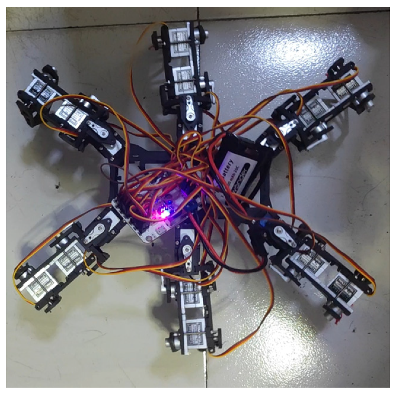
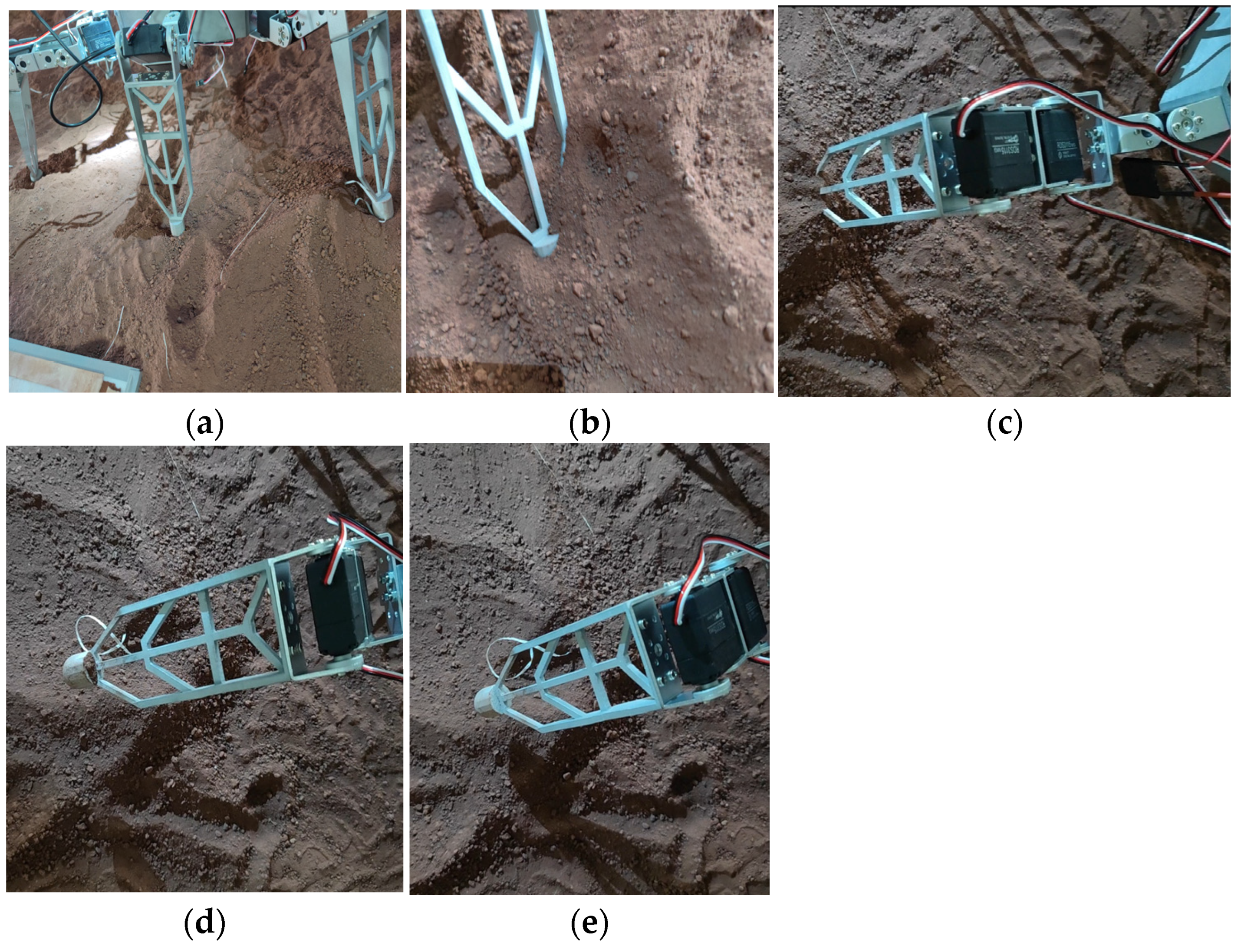
4.3. Robot Prototype Experiment

According to the overall mechanism design and size parameters of the lunar exploration hexapod robot, the test prototype of the robot, as shown in Figure 19, was built.
Place the lunar exploration hexapod robot on the constructed simulated lunar soil test platform for on-site testing to validate the rationality of the overall mechanical structure design. In this experiment, the tripod gait is primarily applied to the physical prototype of the lunar exploration hexapod robot, aiming to verify whether the hollow structure of the robot’s legs can enable it to stand and walk normally on the unstructured terrain of the Moon.
Figure 20 shows the robot’s standing posture in the simulated experiment chamber. In Figure 20a, it can be observed that the spherical design of the robot’s foot end allows it to stand well on the unstructured terrain of simulated lunar soil. Figure 20b depicts the robot’s foot in a small lunar crater, illustrating that the leg design effectively prevents sinking. Figure 20c–e display the robot’s leg positions during lift-off, revealing minor lunar soil adhesion to the robot’s foot after lifting, but the robot’s leg movement effortlessly dislodges the soil particles from the hollow part, with the metal material effectively preventing soil adhesion.
Figure 21 shows the physical image of the lunar exploration hexapod robot in tripod gait walking: Figure 21b represents the posture of the robot’s first group of legs when lifted; Figure 21c shows the posture when the first group of legs lands; and after the landing of the first group of legs, the second group of legs lifts simultaneously, as shown in Figure 21d, achieving the forward gait of the robot through the alternating movement of the two groups of legs.
Through experiments, it has been proven that the mechanical structure of the lunar exploration hexapod robot is reasonable. The hollow structure of its legs reduces the overall weight of the robot while effectively supporting the robot’s weight. This allows the robot to stand stably on the unstructured surface of the Moon. The spherical design of the foot prevents the robot’s foot from sinking, enabling normal standing and walking on lunar soil. Additionally, during walking, lunar soil adhering to the legs can be easily shaken off from the hollow part through leg movements, reducing soil adhesion and achieving the purpose of the hollow design (Supplementary Materials).

5. Conclusions

This paper conducts an overall design of the mechanical structure of lunar exploration robots based on the characteristics of low temperature, low gravity, strong adhesion of lunar soil and strong corrosiveness on the Moon. It uses 3D modeling software to build a three-dimensional model of the lunar exploration hexapod robot and designs an “inverted gait” motion mode based on the tripod gait. In this mode, at the beginning, three legs swing backward, causing the robot to present an inverted posture. This provides a larger swinging space for the robot’s legs. The greater swing of the hip joint improves the effective step length of the robot in a straight motion. It also reduces the pauses during the transition between the swinging and supporting legs, thereby increasing the robot’s forward speed. It enhances the stability of robot motion by reducing joint torque. Subsequently, experiments and comparisons of the two gaits were conducted in simulation software. Data analysis revealed that, in the inverted gait mode, the robot’s displacement distance increased by about 29% in the same time period. It also reduced left and right deviations as well as vertical oscillations during straight-line motion. The angular velocity of the hip joint increased by about 25%, and the maximum peak value of the angular acceleration of the first set of knee joints decreased by about 19.7%, while the second set decreased by about 3.9%. The transition between the swinging of the two leg sets became smoother, enhancing the stability of the robot’s motion. Additionally, the increased swing amplitude of the joints during motion resulted in larger centrifugal forces on the corresponding joint parts, affecting the moment of inertia. The variation in joint swing amplitude also increased the coupling effect between robot joints, reducing the maximum torque borne by the robot’s joints and improving the robot’s load capacity. Finally, experimental tests were conducted on a prototype to verify the rationality of the robot’s structural design. The test results showed that the lunar exploration hexapod robot has a reasonable structure and smooth motion and can achieve the predesigned motion requirements.
However, there are still some issues in the simulation and experimental processes: This paper only conducted simulation studies of the robot’s walking in tripod and inverted gaits under the condition of a sine wave input. Subsequent research should include other input motion laws and the study of quadruped and adaptive gaits. The simulation experiments were carried out with an equivalent simplified model due to the complexity of the actual lunar exploration hexapod robot’s model structure. However, the environment of the Moon is exceptionally unique, with complex and variable conditions, especially a relatively large number of craters and rough terrain. Further analysis is needed to study the kinematics and dynamics of the lunar exploration hexapod robot crawling in craters, aiming to optimize the overall mechanical structure.

Supplementary Materials

The following supporting information can be downloaded at: https://www.mdpi.com/article/10.3390/app14010260/s1.

Author Contributions

Conceptualization, Y.-Q.G. and W.-H.L.; methodology, Y.-Q.G.; software, W.-H.L. and B.-M.S.; validation, Y.-Q.G., Z.-D.X. and W.-H.L.; formal analysis, Y.-Q.G., W.-H.L. and B.-M.S.; investigation, Z.-D.X. and D.-K.Y.; resources, Y.-Q.G. and Z.-D.X.; data curation, Y.-Q.G., W.-H.L. and D.-K.Y.; writing—original draft preparation, Y.-Q.G. and W.-H.L.; writing—review and editing, Y.-Q.G. and W.-H.L.; visualization, Y.-Q.G. and W.-H.L.; supervision, Y.-Q.G.; project administration, Y.-Q.G.; funding acquisition, Z.-D.X. All authors have read and agreed to the published version of the manuscript.

Funding

This research was funded by the National Natural Science Foundation of China (NSFC) Integrated Project, grant number U2037602.

Institutional Review Board Statement

Not applicable.

Informed Consent Statement

Not applicable.

Data Availability Statement

Data is contained within the article and supplementary material.

Conflicts of Interest

The authors declare no conflicts of interest.

References

  1. Wedler, A.; Schuster, M.J.; Müller, M.G.; Vodermayer, B.; Meyer, L.; Giubilato, R.; Vayugundla, M.; Smisek, M.; Dömel, A.; Steidle, F. German Aerospace Center’s Advanced Robotic Technology for Future Lunar Scientific Missions. Philos. Trans. R. Soc. A 2021, 379, 20190574. [Google Scholar] [CrossRef] [PubMed]
  2. Yang, L.; Li, Y.; Zhang, Y. Numerical Investigation of the Ground-Based Thermal Environment Experimental Approaches to Reveal the Ice-Sublimation Phenomenon inside Lunar Regolith. Acta Astronaut. 2023, 205, 295–309. [Google Scholar] [CrossRef]
  3. OuYang, Z.Y. International Lunar Exploration Progress and Chinese Lunar Exploration. Bull. Geol. Sci. Technol. 2004, 23, 1–5. [Google Scholar] [CrossRef]
  4. Solot, E. Improving the Traction of a Legged Rover: A Biomimetic Approach. Master Thesis, Delft University of Technology, Delft, The Netherlands, 2022. [Google Scholar]
  5. Zheng, Y.C.; OuYang, Z.Y.; Wang, S.J.; Zou, Y.L. Physical and Mechanical Properties of Lunar Regolith. Mineral. Petrol. 2004, 24, 14–19. [Google Scholar] [CrossRef]
  6. Zhao, Y.T. Time-cost Heuristic Planning Method for Multi-robot Cooperative Lunar Mission. J. Astronaut. 2022, 43, 1277–1290. [Google Scholar] [CrossRef]
  7. Qin, R.P.; Xu, K.; Chen, J.W.; Han, L.L.; Ding, X.L. Design and Motion Planning of Wheel-legged Hexapod Robot for Planetary Exploration. Acta Aeronaut. Astronaut. Sin. 2021, 42, 154–164. [Google Scholar] [CrossRef]
  8. Xiong, G.; Guo, X.; Yuan, S.; Xia, M.; Wang, Z. The Mechanical and Structural Properties of Lunar Regolith Simulant Based Geopolymer under Extreme Temperature Environment on the Lunar through Experimental and Simulation Methods. Constr. Build. Mater. 2022, 325, 126679. [Google Scholar] [CrossRef]
  9. Jiang, S.; Song, W.; Zhou, Z.; Sun, S. Stability Analysis of the Food Delivery Robot with Suspension Damping Structure. Heliyon 2022, 8, e12127. [Google Scholar] [CrossRef]
  10. Nguyen, H.D.; Dung, V.T.; Sato, H.; Vo-Doan, T.T. Efficient Autonomous Navigation for Terrestrial Insect-Machine Hybrid Systems. Sens. Actuators B Chem. 2023, 376, 132988. [Google Scholar] [CrossRef]
  11. Jang, W.S.; Huang, W.; Shen, Z.W.; Wang, H.T. Soft Landing Dynamics Simulation for Lunar Explorer. J. Astronaut. 2011, 32, 462–469. [Google Scholar] [CrossRef]
  12. Hoshino, K.; Igo, N.; Tomida, M.; Kotani, H. Teleoperating System for Manipulating a Moon Exploring Robot on the Earth. Int. J. Autom. Technol. 2017, 11, 433–441. [Google Scholar] [CrossRef]
  13. Chen, J.; Xie, F.; Huang, L.; Yang, J.; Liu, X.; Shi, J. A Robot Pose Estimation Optimized Visual SLAM Algorithm Based on CO-HDC Instance Segmentation Network for Dynamic Scenes. Remote Sens. 2022, 14, 2114. [Google Scholar] [CrossRef]
  14. Si, W.; Zhu, Z.; Wu, G.; Zhang, Y.; Chen, Y.; Sha, J. Encoding Manipulation of DNA-Nanoparticle Assembled Nanorobot Using Independently Charged Array Nanopores. Small Methods 2022, 6, 2200318. [Google Scholar] [CrossRef]
  15. Geng, D.X.; Peng, H.; Zhang, J.T.; Zhao, Y.W.; Wu, G.B. Research on Structure and Kinematics of Hexapod Robot Based on the Pneumatic Flexible Joint. Appl. Mech. Mater. 2013, 401–403, 267–271. [Google Scholar] [CrossRef]
  16. Luo, X.; Ding, X.J. Research and Prospective of Motion Planning and Control of Ground Mobile Manipulators. J. Harbin Inst. Technol. 2021, 53, 1–15. [Google Scholar] [CrossRef]
  17. Coelho, J.; Ribeiro, F.; Dias, B.; Lopes, G.; Flores, P. Trends in the Control of Hexapod Robots: A Survey. Robotics 2021, 10, 100. [Google Scholar] [CrossRef]
  18. Zhu, Y.; Jin, B.; Li, W.; Li, S. Optimal Design of Hexapod Walking Robot Leg Structure Based on Energy Consumption and Workspace. Trans. Can. Soc. Mech. Eng. 2014, 38, 305–317. [Google Scholar] [CrossRef]
  19. Jahagirdar, N.; Hiremath, A.; Balan, S.; Sathiyanarayanan, M. Enhanced Road Edge Detection (E-RED) for an Autonomous Planetary Rover. In Proceedings of the 3rd International Conference on Applied and Theoretical Computing and Communication Technology (iCATccT), Tumkur, India, 21–23 December 2017; pp. 13–17. [Google Scholar] [CrossRef]
  20. Xiao, T.Y. Structure Design and Gait Planning of Structure Design and Gait Planning of Heavy-Duty Hexapod Robot. Master’s Thesis, Xihua University, Chengdu, China, 2019. [Google Scholar]
  21. Fan, J.Z.; Xiao, B.L.; Xu, J.; Shi, L.K. Development and Applications of SiCp/Al Composites in Aerospace Field. Mater. Herald. 2007, 21, 98–101. [Google Scholar] [CrossRef]
  22. Si, L.; Liu, C.; Yan, H.; Wang, Y.; Yang, Y.; Zhang, S.; Zhang, Y. The Influences of High Temperature on Tribological Properties of Cu-Based Friction Materials with a Friction Phase of SiO2/SiC/Al2O3. AIP Adv. 2021, 11, 025335. [Google Scholar] [CrossRef]
  23. Chen, J.; Gu, L.; Zhao, W.; Guagliano, M. Simulation of Temperature Distribution and Discharge Crater of SiCp/Al Composites in a Single-Pulsed Arc Discharge. Chin. J. Aeronaut. 2021, 34, 37–46. [Google Scholar] [CrossRef]
  24. Lordos, G.; Brown, M.J.; Latyshev, K.; Liao, A.; Shah, S.; Meza, C.; Bensche, B.; Cao, C.; Chen, Y.; Miller, A.S. WORMS: Field-Reconfigurable Robots for Extreme Lunar Terrain. In Proceedings of the IEEE Aerospace Conference, Big Sky, MT, USA, 4–11 March 2023; pp. 1–21. [Google Scholar] [CrossRef]
  25. Yang, C.; Zhang, X.; Bruzzone, L.; Liu, B.; Liu, D.; Ren, X.; Benediktsson, J.A.; Liang, Y.; Yang, B.; Yin, M.; et al. Comprehensive Mapping of Lunar Surface Chemistry by Adding Chang’e-5 Samples with Deep Learning. Nat. Commun. 2023, 14, 7554. [Google Scholar] [CrossRef] [PubMed]
  26. Ye, P.J.; Xiao, F.G. Issues about Lunar Environment in Lunar Exploration Project. Spacecr. Environ. Eng. 2006, 23, 1–11. [Google Scholar] [CrossRef]
  27. Zhang, Y.; Qiao, G.; Wan, Q.; Tian, L.; Liu, D. A Novel Double-Layered Central Pattern Generator-Based Motion Controller for the Hexapod Robot. Mathematics 2023, 11, 617. [Google Scholar] [CrossRef]
  28. Bai, L.; Hu, H.; Chen, X.; Sun, Y.; Ma, C.; Zhong, Y. CPG-Based Gait Generation of the Curved-Leg Hexapod Robot with Smooth Gait Transition. Sensors 2019, 19, 3705. [Google Scholar] [CrossRef] [PubMed]
  29. Liu, Y.; Fan, X.; Ding, L.; Wang, J.; Liu, T.; Gao, H. Fault-Tolerant Tripod Gait Planning and Verification of a Hexapod Robot. Appl. Sci. 2020, 10, 2959. [Google Scholar] [CrossRef]
  30. Song, X.; Zhang, X.; Meng, X.; Chen, C.; Huang, D. Gait Optimization of Step Climbing for a Hexapod Robot. J. Field Robot. 2022, 39, 55–68. [Google Scholar] [CrossRef]
  31. Zhai, S.; Jin, B.; Cheng, Y. Mechanical Design and Gait Optimization of Hydraulic Hexapod Robot Based on Energy Conservation. Appl. Sci. 2020, 10, 3884. [Google Scholar] [CrossRef]
  32. Zhang, F.; Zhang, S.; Wang, Q.; Yang, Y.; Jin, B. Straight Gait Research of a Small Electric Hexapod Robot. Appl. Sci. 2021, 11, 3714. [Google Scholar] [CrossRef]
Figure 1. Overall structure of the lunar exploration hexapod robot.
Applsci 14 00260 g001
Figure 2. Schematic diagram of the fuselage layout.
Applsci 14 00260 g002
Figure 3. Leg structure of hexapod insects.
Applsci 14 00260 g003
Figure 4. RDS3115 servo.
Applsci 14 00260 g004
Figure 5. Leg structure of the lunar exploration hexapod robot.
Applsci 14 00260 g005
Figure 6. D-H coordinate system of the robotic leg.
Applsci 14 00260 g006
Figure 7. Sketch of the overall structure of the lunar exploration hexapod robot.
Applsci 14 00260 g007
Figure 8. Conventional gait diagram of the lunar exploration hexapod robot: (a) robot initial state; (b) robot morphology at 1 s; (c) robot morphology at 2 s; (d) robot morphology at 3 s; (e) robot morphology at 4 s; (f) robot morphology at 5 s.
Applsci 14 00260 g008
Figure 9. Tripod gait timing diagram: The numbers indicate leg numbers.
Applsci 14 00260 g009
Figure 10. The “inverted gait” diagram of the lunar exploration hexapod robot: (a) initial state of the robot; (b) robot morphology at 0.5 s; (c) robot morphology at 1 s; (d) robot morphology at 2 s; (e) robot morphology at 3 s; (f) robot morphology at 4 s.
Applsci 14 00260 g010aApplsci 14 00260 g010b
Figure 11. Inverted gait timing diagram: The numbers indicate leg numbers.
Applsci 14 00260 g011
Figure 12. Displacement curves of the center of mass of the lunar exploration hexapod robot: (a) robot’s center of mass displacement along the y-axis; (b) robot’s center of mass displacement along the x-axis; (c) robot’s center of mass displacement along the z-axis.
Applsci 14 00260 g012
Figure 13. Angular velocity curves of robot’s hip joint rotation: (a) first group of robotic legs; (b) second group of robotic legs.
Applsci 14 00260 g013
Figure 14. Angular velocity curves of the robot’s rotating knee joints: (a) first group of robotic legs; (b) second group of robotic legs.
Applsci 14 00260 g014
Figure 15. Angular acceleration curves of the robot’s hip joint: (a) first group of robotic legs; (b) second group of robotic legs.
Applsci 14 00260 g015
Figure 16. Angular acceleration curves of the robot’s knee joint: (a) first group of robotic legs; (b) second group of robotic legs.
Applsci 14 00260 g016
Figure 17. Robotic hip torque curves: (a) first group of robotic legs; (b) second group of robotic legs.
Applsci 14 00260 g017
Figure 18. Robotic knee torque curves: (a) first group of robotic legs; (b) second group of robotic legs.
Applsci 14 00260 g018
Figure 19. Prototype of the lunar exploration hexapod robot.
Applsci 14 00260 g019
Figure 20. Robots in the simulation chamber: (a) robot’s standing posture; (b) simulation of a robotic foot end in a small lunar crater; (c) end of a foot caught in the Moon’s soil; (d) lunar loam attached to the end of the foot after elevation; (e) robot’s legs after dumping lunar soil.
Applsci 14 00260 g020
Figure 21. Diagram of the lunar exploration hexapod robot walking in a straight line: (a) initial state; (b) the first group lifted; (c) the first group landed; (d) the second group lifted; (e) the second group landed; (f) the fuselage returned to its initial state.
Applsci 14 00260 g021
Table 1. Various performance parameters of SiCp/Al composites.
PropertiesSiCp/Al
Density/(g/cm3)2.94
Modulus of elasticity/Gpa213
Specific modulus/105 m72.4
Thermal conductivity/(W·m−1·K−1)195.6
Thermal expansion coefficient/106K−18.0
Tensile strength/Mpa363.4
Table 2. Servo’s detailed parameters.
ItemSpecification
Operating voltage5–7.2 V
Operating speed (at no load)0.13 s/60°
Running current (at no load)100 mA
Stall torque (at locked)15 kg∙cm
Stall current (at locked)1.5 A
Idle current5 mA
Operating frequency50–330 Hz
Pulse-width range500–2500 µs
Table 3. D-H parameters of the robotic leg.
Joint θ i α i l i
Hip θ 1 π / 2 l 1
Knee θ 2 0 l 2
Ankle θ 3 0 l 3
where θ i is the linkage pinch angle of the ith leg of the hexapod robot; α i is the torsion angle, which denotes the angle of the rotation around x i so that z ( i 1 ) is parallel to z i ; l i is the linkage length of the ith leg of the hexapod robot; and d i is the distance of the neighboring joints from the common plumb line.
Table 4. Contact force parameter settings.
ParameterSetpoint
Contact Typeentity
Stiffness100.0 (N.mm)
Force Exponent2.2
Damping10.0 (Ns/mm)
Penetration Depth0.1 (mm)
Coulomb FrictionOn
Static Coefficient0.75
Dynamic Coefficient0.75
Station Transition Vel.100.0 (mm/s)
Friction Transition Vel.100.0 (mm/s)
ParameterSetpoint
Disclaimer/Publisher’s Note: The statements, opinions and data contained in all publications are solely those of the individual author(s) and contributor(s) and not of MDPI and/or the editor(s). MDPI and/or the editor(s) disclaim responsibility for any injury to people or property resulting from any ideas, methods, instructions or products referred to in the content.

