Article

Estimation of Cervical Spinal Loading and Internal Motion at Adjacent Segments after C5–C6 Fusion Using a Musculoskeletal Multi-Body Dynamics Model during the Head Flexion–Extension Movement

1
School of Mechanical Engineering, Shijiazhuang Tiedao University, Shijiazhuang 050043, China
2
College of Mechanical and Electrical Engineering, Shaanxi University of Science & Technology, Xi’an 710021, China
3
State Key Laboratory for Manufacturing Systems Engineering, School of Mechanical Engineering, Xi’an Jiaotong University, Xi’an 710054, China
4
Tribology Research Institute, School of Mechanical Engineering, Southwest Jiaotong University, Chengdu 610031, China
5
Institute of Medical and Biological Engineering, School of Mechanical Engineering, University of Leeds, Leeds LS2 9JT, UK
*
Author to whom correspondence should be addressed.
Appl. Sci. 2024, 14(1), 261; https://doi.org/10.3390/app14010261
Submission received: 5 December 2023 / Revised: 22 December 2023 / Accepted: 27 December 2023 / Published: 28 December 2023

Abstract

:
Cervical spinal fusion is the standard of care for treating intractable spinal diseases. However, frequent adjacent segment disease (ASD) has recently drawn a great deal of attention among clinicians and researchers. At present, the etiology of ASD remains controversial. The investigation of cervical spine biomechanics after fusion may contribute to understanding the causes of ASD. In the present study, a cervical spinal musculoskeletal fusion model, with multi-body dynamics method, was established. Dynamic head flexion–extension movements were simulated for both a fusion subject and a normal subject. The cervical spinal loading pattern, load sharing ratios, and translations of instant centers of the rotation at adjacent segments were then predicted. The average intervertebral compressive forces, shear forces, and facet joint forces against the intervertebral angle were also obtained. By comparison, some obvious differences in cervical spinal loading patterns were found between the fusion subject and the normal subject. Fusion surgery would alter the postoperative biomechanical surrounding of the cervical spine, especially the adjacent segments. These changes might affect the intervertebral disc-bearing capacity, and even weaken the physiological structure. From a purely biomechanical perspective, the cervical spinal fusion model can contribute to comprehending the etiology of ASD after spinal fusion.

1. Introduction

Cervical spinal fusion surgery, as a standard surgical procedure, has been widely applied for treating serious cervical spinal diseases [1]. Although the success and satisfaction of cervical spinal fusion surgery have been significantly improved over the years, adjacent segment disease (ASD), as a common postoperative complication, has become a major clinical concern for long-term prospective outcomes, due to its high incidence [2,3]. Several reported follow-up studies documented that the high occurrence of ASD after cervical spinal fusion is about 3% per year [2,3]. Moreover, the incidence of ASD after spinal fusion has grown per year, even up to 25% at 10 years. For serious complication after spinal fusion, the rate of revision, whereby the patients need reoperation, is approximately 21% of the total ASD incidence. However, the etiology of ASD remains controversial, while multiple risk factors have been determined to date [2,4,5,6]. Increased motion, excessive biomechanical loading, and abnormal sagittal alignment at adjacent segments can result in the occurrence of ASD, in addition to the natural process of cervical disc degeneration [3,5].
After cervical spinal fusion, motion in the treated level is eliminated. In contrast, ranges of motion at adjacent segments generally increase in daily activities, due to the compensatory effect [7]. On the other hand, joint biomechanics is known to affect intervertebral disc degeneration [8,9,10]. It is believed that the cervical spinal fusion surgery-induced acceleration of intervertebral disc degeneration may be derived from increased internal stress [11,12]. As clinical follow-ups have primarily focused on radiographic changes for ASD, the biomechanical results of spinal fusion are commonly studied through in vitro cadaveric experiments or computational models [12,13,14,15]. In vitro experiments often aim to address the influence of implants on the adjacent segments or whole columns, such as spinal kinematics and intradiscal pressure (IDP) [12,13]. However, these experiments always had certain assumptions that may lead to obtaining different, even contradictory findings [16]. Moreover, currently adopted in vitro experiments have limitations in simulating in vivo dynamic motion of the cervical spine [16].
As an alternative, computational models combined with accurate anatomical data have been introduced to obtain valuable joint mechanics. The cervical spinal loading patterns during various head movements have been estimated by the musculoskeletal (MSK) model, based on the multi-body dynamics (MBD) method [17]. However, the obtained cervical spinal loading patterns, such as compressive forces (CFs), shear forces (SFs), and facet joint forces (FJFs), only represent the normal subject (NS) [17]. According to the in vivo cervical spine kinematics, there are significant differences in motion patterns between the fusion subject (FS) and the NS [7]. In vivo dynamic motion patterns at adjacent segments after spinal fusion are redistributed during the head flexion–extension (F/E) movement. Moreover, the cervical spinal loading pattern is disc angle-dependent and level-dependent [17]. Hence, it is believed that the spinal loading patterns and internal motion after cervical spinal fusion might be altered as well. An investigation of the biomechanics after fusion may contribute to comprehending the inherent relationship between the motion and spinal loading of the cervical spine. Moreover, the MSK cervical spinal fusion model, combined with the MBD method, offers a possible approach to explore the possible etiology of ASD.
Therefore, this study aimed to develop a more detailed MSK MBD cervical spinal fusion model and to estimate the spinal loading and translations of instant centers of rotation (ICRs) at adjacent segments during the head F/E movement. The normal cervical spinal loading and translations of ICRs were also considered for comparative purposes.

2. Materials and Methods

2.1. The Normal Cervical Spine Model

A pre-established cervical spine MSK MBD model was used to represent the NS for biomechanical analysis [17]. This normal cervical spine model was developed in the software AnyBody Modeling System (version 6.0; AnyBody Technology, A/S, Aalborg, Denmark) via the force-dependent kinematics approach [18,19]. It consisted of the skull, 7 cervical vertebrae, 12 thoracic vertebrae, 5 lumbar vertebrae, and a pelvis part. For the efficiency of simulation, a rigid constraint was formed by the thoracic-lumbar column and pelvis part. A six-degree-of-freedom (DOF) disc and cervical ligaments among whole columns were defined. A novel contact pair, representing a type of spherical point-cloud joint, was used to model the facet joint among adjacent segments. The nonlinear property of the facet joint was realized through the internal process of the spherical point-cloud joint. In addition, several muscle bundles were included to represent major cervical spine muscles in the normal model. The specific modeling process of this normal model was particularly described in the original journal [17].

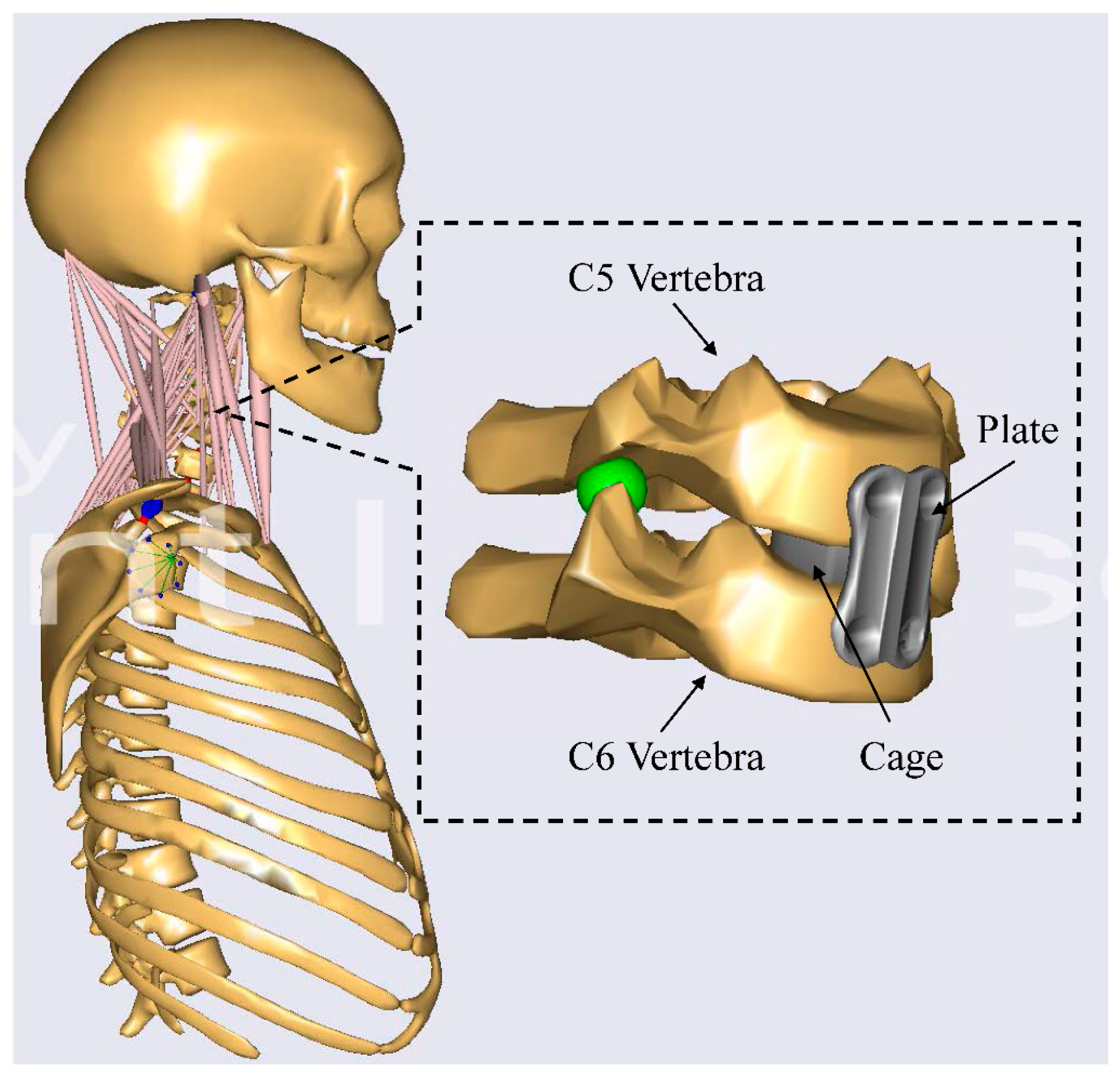
2.2. The Cervical Spinal Fusion Model

The cervical spinal fusion model was developed based on the aforementioned normal model. In the fusion model, a plate and cage were implanted at C5–C6 to simulate the postoperative fusion condition (Figure 1). To exactly match postoperative anatomical features, some adjustments to the cervical spinal model were performed.
Firstly, sagittal angles among disc levels in the neutral position were modified, according to the published postoperative sagittal alignment [7]. In the fusion model, the fused level presented significant kyphosis. For the adjacent segments, the postoperative superior adjacent segment was slightly lordosis, but trended towards kyphosis, while the inferior was more lordosis. Minor adjustments were performed for the remaining disc levels.
Secondly, based on the features of in vivo dynamic kinematics after cervical spinal fusion, the postoperative cervical spine rhythms were also adjusted. After spinal fusion, the cervical spine tends to move more extensively. Hence, the new fused cervical spine rhythms in the head flexion or extension phase were respectively generated, according to in vivo kinematics observations [7,20]. The fused level (C5–C6) was able to perform small relative motion, rather than absolute rigid fusion in the new fused rhythms. In addition, the maximal ranges of head motion were adopted in the present study, where the head flexion–extension movement was a representative cosine curve [17].
To assess the effect of cervical spinal fusion on biomechanics, the normal model was also modified subsequently. In the normal model, the cervical spine rhythms in the head flexion or extension phase were not distinguished, different from the new fused rhythms. Moreover, the sagittal angles of disc levels in the normal model were normal lordosis, representing an idealized sagittal alignment. Similarly, the same magnitude and form of head motion were also inputted to the normal model.

2.3. Inverse Dynamics Analysis

The inverse dynamics analysis was subsequently implemented when motion data was inputted into the AnyBody Modeling System. In the model simulation process, joint reaction forces and muscle forces were estimated through predefined motion [19]. Since the MSK model has a large number of muscles, the model is usually turned into an over-determined system. To solve this non-unique solution, the muscle recruitment problem is converted to an optimization problem [21]. Hence, the muscle recruitment criterion is applied in the optimization routine. In the present study, a cubic polynomial optimality criterion as the objective function was adopted, as well as a muscle recruitment criterion. The force-dependent kinematics approach was introduced to predict the translations of ICRs, due to soft tissue deformation in the present study. A force-dependent kinematics approach was performed within inverse dynamics analysis, based on the assumption of quasi-static force equilibrium. This approach assumes that dynamic effects produced by the secondary joint DOFs, within the small movements in these DOFs, will be negligible. At each analysis step, an iterative algorithm is employed and converged by the internal force-dependent kinematics solver [19]. Hence, the cervical spine MSK MBD fusion model can simultaneously predict spinal loading and joint internal motion.

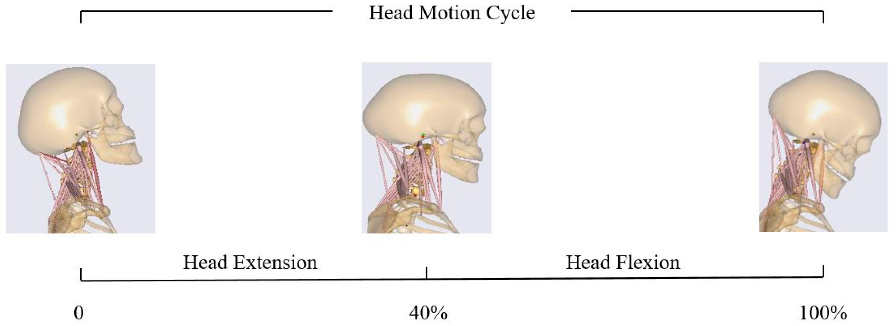
2.4. Flexion–Extension Simulation

Dynamic simulation of the head F/E movement was performed by the fusion model (Figure 2). Normal head flexion–extension movement was also simulated. For comparative purposes, an identical head motion pattern was adopted in both cervical spine models. At adjacent segments, cervical spinal loading, including CF, SF, and FJF, was predicted via either the normal model or the fusion model. Moreover, the spinal load sharing ratios, representing the CF and the part of FJF in compression against the total internal force in compression, were also calculated. The anterior–posterior (A-P) and superior–inferior (S-I) translations of ICRs were simultaneously obtained by the MBD models. To identify the difference between the FS and the NS on joint internal motion, the change in the A-P translations of ICRs was also calculated.

3. Results

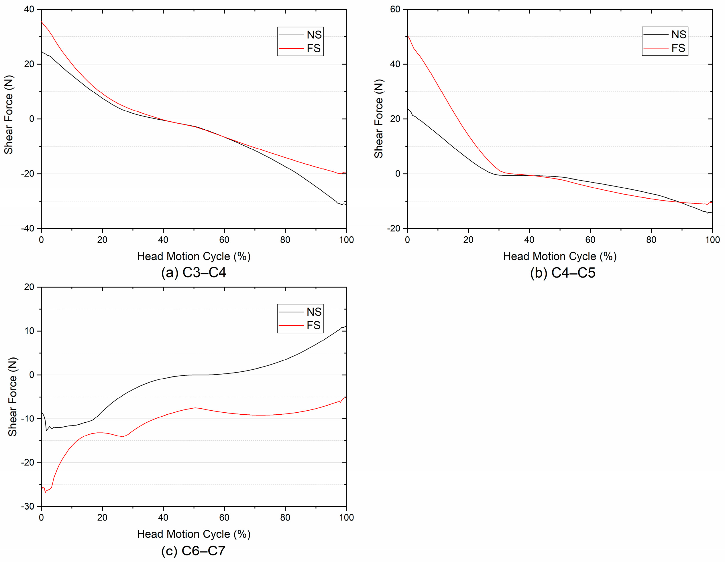
3.1. Compressive and Shear Forces

The comparison of the predicted CFs between the FS and the NS during the head F/E movement at C3–C7 are shown in Figure 3. In general, under the same range of head motion, no differences in amplitude of CFs between the FS and the NS were found during the head flexion movement (Figure 3). However, in the head extension phase, there were obvious differences in the trends of CFs between the FS and the NS (Figure 3). For instance, the FS had always higher peak values of CF than that of the NS. At C4–C5 and C6–C7, the magnitudes of the CFs of the FS were obviously lower than the values of the NS during the middle of the head extension movement. In contrast, the magnitudes of the CFs of the FS at C3–C4 were mostly greater in comparison to the NS in the head extension phase.
Figure 4 shows the comparison of the predicted A-P SFs between the FS and the NS at C3–C7 in the whole head F/E phase. At the superior adjacent segments, there were minor variations in the A-P SFs between the FS and the NS during the head flexion movement (Figure 4). However, in the head extension phase, an obvious increase in the magnitude of the A-P SF of the FS was found at C4–C5. At the inferior adjacent segments, there was a significant variation in the values of the A-P SF of the FS at C6–C7, compared with the NS during the whole head motion (Figure 4c). After fusion surgery, the A-P SF was obviously increased during the head extension movement. In contrast, an obvious change in the direction of the A-P SF of the FS was found in the head flexion phase. In general, the A-P SF after spinal fusion trended towards the posterior direction at C6–C7.

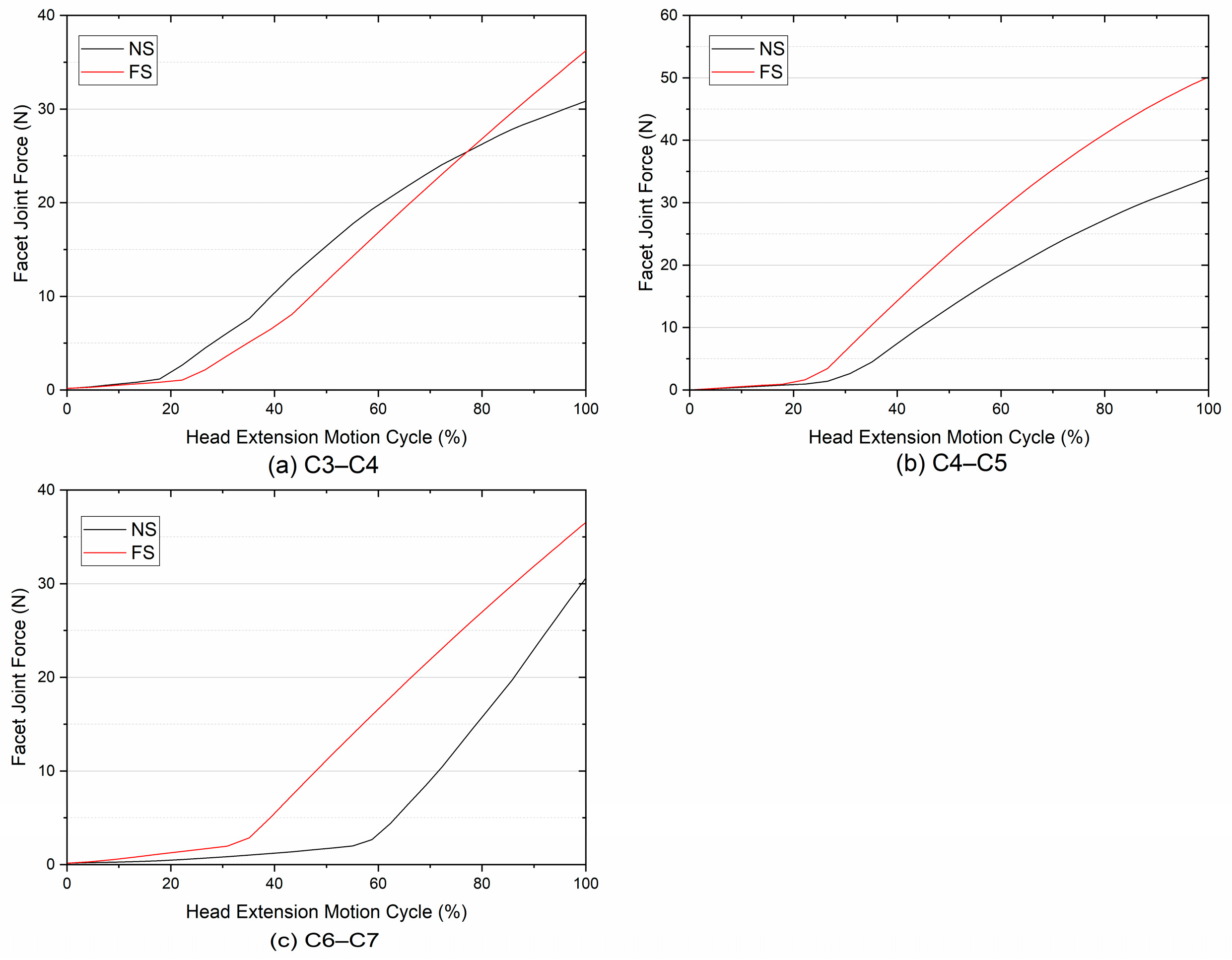
3.2. Facet Joint Force

The comparison of the predicted FJFs between the FS and the NS at C3–C7 in the head extension phase are shown in Figure 5. Larger increases at C4–C5 and C6–C7 were found on the magnitude of FJFs. For C3–C4, the variations of FJFs between the FS and the NS were not obvious. Figure 6 shows comparisons of the experimentally measured and computationally estimated change in the FJFs of the FS, relative to the NS [12]. For C4–C5, the predicted change was up to 47.4%, greater than the published experimental results (28.2 ± 10.7%). For the inferior adjacent segment, the computationally estimated change was in conformity with the experimental measurement.

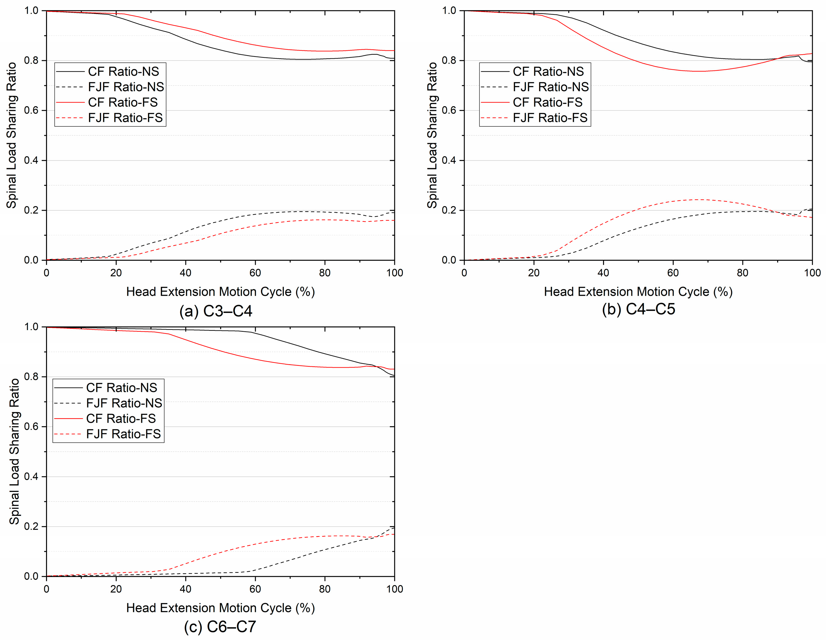
3.3. Spinal Load Sharing in Compression
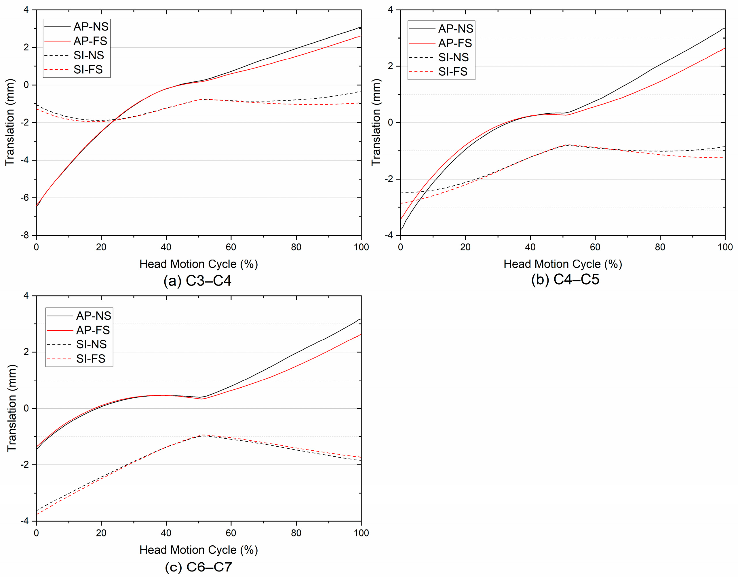
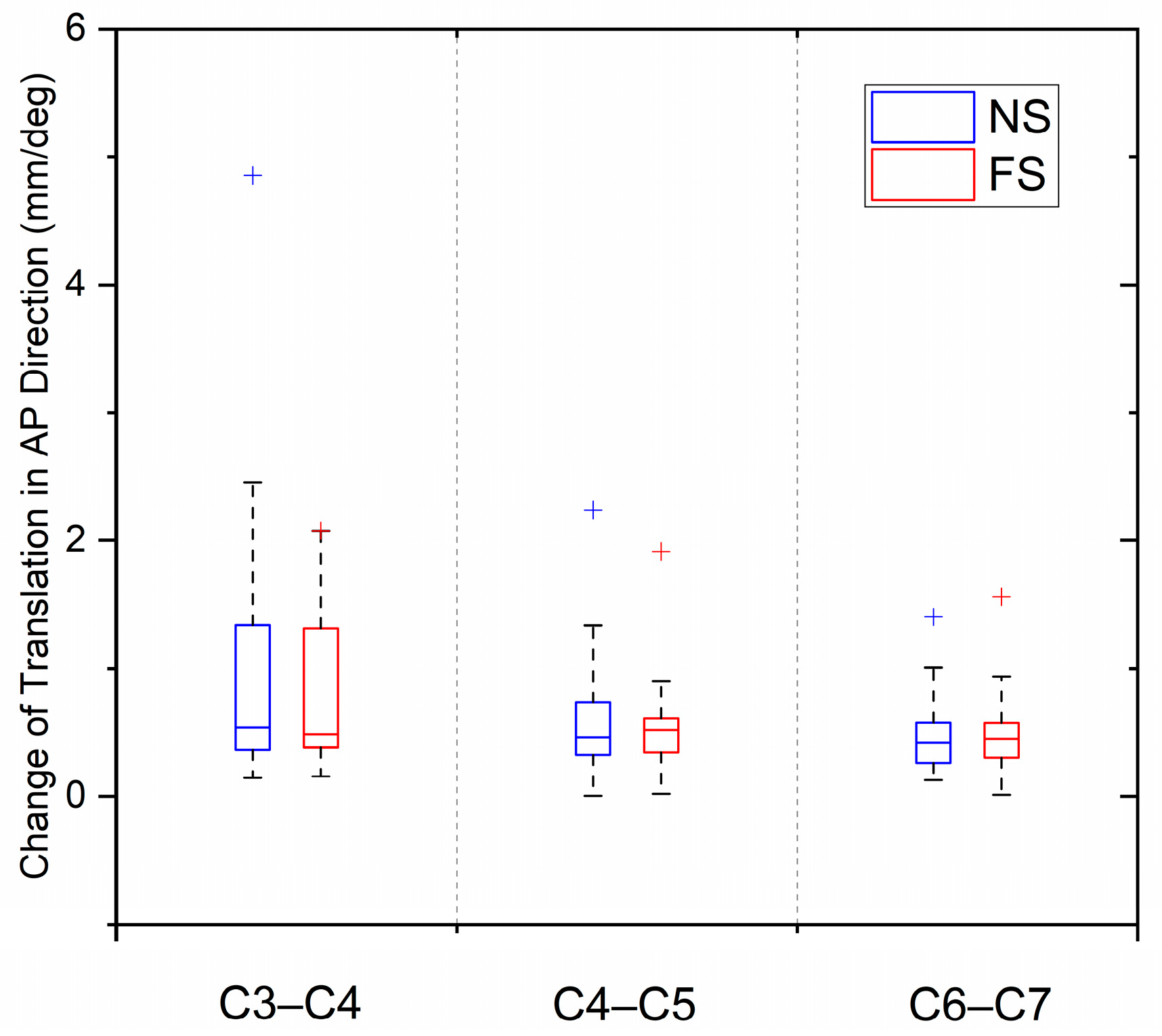
The spinal load sharing ratios in compression of the FS and the NS at adjacent segments in the head extension phase are shown in Figure 7. At the beginning of head extension motion cycle (0–20%), both of the load sharing ratios of the CFs were almost close to 1. Similarly, both of the load sharing ratios of the CFs accounted for approximate 0.8 at the end-stage (80–100%). However, some differences in the spinal load sharing ratios among adjacent segments were found between the FS and the NS at the middle range (20–80%). For C3–C4, the load sharing ratios of CFs of the FS were usually higher than that of the NS, where the postoperative disc needed to bear more spinal loading. In contrast, for C4–C5 and C6–C7, this load sharing phenomenon was reverse. In conclusion, the variations of load-sharing ratios after cervical spinal fusion were more obvious during the middle range of the head extension motion cycle.

3.4. Translation

Comparisons of the predicted A-P and S-I translations of ICRs between the FS and the NS during the head F/E movement at C3–C7 are shown in Figure 8. No significant differences in translations of ICRs at adjacent segments were found between the FS and the NS. The boundaries of incremental changes in the A-P translation of ICRs overlapped between the FS and the NS (Figure 9). The average incremental change of the FS at C3–C4, C4–C5, and C6–C7 was 0.80, 0.50 and 0.46 mm/deg, respectively, while the root mean square error was 0.04, 0.02, and 0.02 mm/deg, respectively. Similarly, the average incremental change of the NS at C3–C4, C4–C5, and C6–C7 was 1.13, 0.62, and 0.48 mm/deg, respectively, while the root mean square error was 0.13, 0.06, and 0.03 mm/deg, respectively.

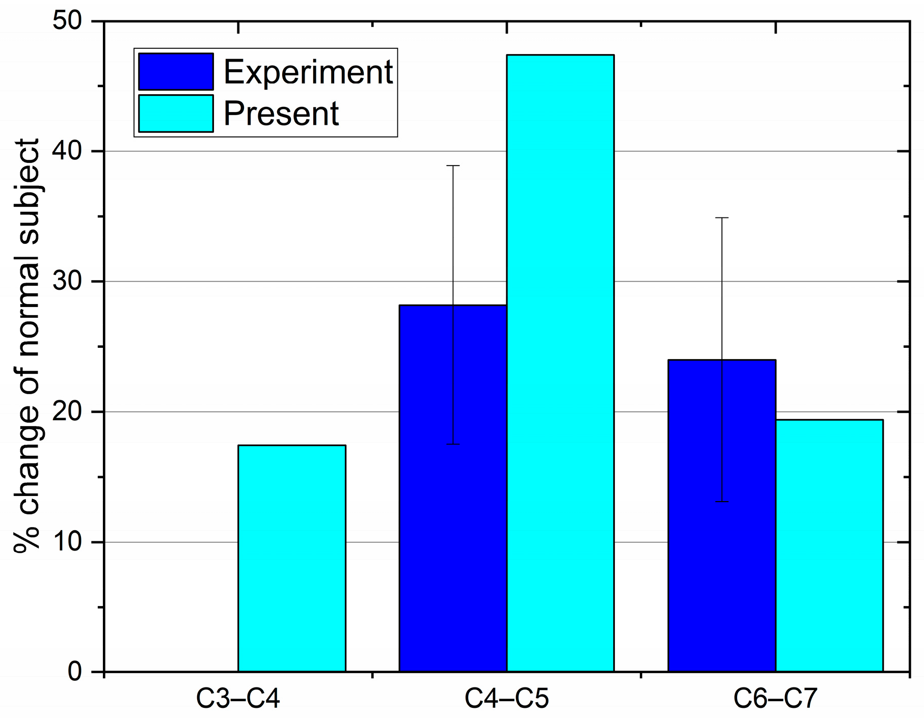
3.5. Biomechanical Comparison

The average CFs and SFs and the corresponding FJFs between the FS and the NS against the intervertebral angle in the whole head F/E phase are reported in Table 1 and Table 2. For average CFs, SFs, and FJFs at each intervertebral angle interval, significant differences between the FS and the NS were found. The increments of the average CFs of the FS at C3–C4 were almost greater than those of the NS throughout the whole head motion cycle. For C4–C5 and C6–C7, the increments of the average CFs of the FS were lower than those of the NS in the middle of the head motion cycle, while greater increments of the FS were observed in the beginning or end-stage of head motion cycle. For average SFs and FJFs, the increments between the FS and the NS were similar at the same intervals.

4. Discussion

According to previous studies, the etiology of ASD is considered to be excessive loading and abnormal sagittal alignment [3,5,8,9,22]. Among these causes, joint mechanics may act as an important factor affecting adjacent segment degeneration [8,22]. However, the association between postoperative cervical spinal biomechanics and ASD remains uncertain. Hence, from a biomechanical perspective, we tried to understand the effects of spinal fusion surgery on the adjacent segments using a cervical spine MSK MBD model.
For the inverse dynamics analysis, the input motion data after spinal fusion is a key factor for the accuracy and reliability of the MSK MBD simulation. As mentioned above, the segmental motion after cervical spinal fusion is different from the normal condition, according to the in vivo kinematics observation [7]. Limited ROM and the re-distributed cervical spine rhythm after spinal fusion were both considered in the fusion model. In this way, spinal loading and internal motion after cervical spinal fusion were predicted. In summary, the spinal loading pattern after fusion presents a distinctly level-dependent feature, similar to the NS. However, there are still some differences in spinal loading patterns between the FS and the NS.
Firstly, regarding the maximum CF, the FS was about 25% greater than the NS in the head extension phase (Figure 3). A significant increase in adjacent IDPs after spinal fusion was also found in the in vitro investigations [12,13]. Eck et al. [13] reported that IDPs at adjacent segments after C5–C6 fusion increased by 20.7% in the extension phase according to the cadaveric experiment. Chang et al. [12] found a significant increase (up to 46.5 ± 18.8%) in IDP at the superior segment during the extension movement. Excessive spinal loading after fusion would be bound to affect the intervertebral disc-bearing capacity, even to damage its physiological structure [9]. By contrast, the same magnitudes and trends were predicted in the head flexion phase. Differently, the increments of the average CFs of the FS during the head flexion movement were mostly greater than those of the NS at the superior adjacent segments (Table 2). Moreover, according to the in vivo dynamic motion, the postoperative ROMs of the head flexion of fusion patients were decreased [20]. The predicted results indicated that adjacent segments after fusion would sustain more loading under the same intervertebral motion angle. These obvious postoperative changes of the spinal biomechanics might affect the structure and function of spinal soft tissues. Adams et al. [8] stated that a weakened intervertebral disc structure is the main cause of the disc degeneration process. Similarly, Hutton et al. [23] indicated that an increased CF persistently applied to the disc would change the physiological structure over a period of time. Presumably, these postoperative variations might result in accelerated disc degeneration over the years. Hence, treated patients should be advised to avoid excessive motion in daily activities.
Secondly, minor variations in the A-P SFs at the superior adjacent segments were found between the FS and the NS, except for the beginning and end stages of the head motion cycle. Particularly, an obvious increase in the head extension phase was found at C4–C5. Excessive shear stress may result in the circumferential tears of the disc, thus leading to structural failure, even disc degeneration [8,24]. For the inferior adjacent segment, the A-P SF after spinal fusion trends towards the posterior direction in comparison to the NS. In the simulation process, almost the same ROMs of C6–C7 between the FS and the NS were adopted during the head flexion movement. Unlike the normal model, the sagittal angle of C6–C7 in the fusion model was modified to more lordosis. Hence, postoperative sagittal alignment in the fusion model trends towards imbalance. The alteration of sagittal alignment could be the result of the alteration of the A-P SFs, further leading to an imbalanced structure. Benditz et al. [25] found that the decrease in the A-P SFs during the flexion movement could be correlated with the sagittal imbalance in the thoracic-lumbar region. A systematic review of ASD etiology stated that abnormal stresses resulting from imbalanced alignment after spinal fusion appear to lead to ASD [5]. However, there is still no definitive evidence that ASD is distinctly related to a decrease in SF. The relationship between ASD and SF should be investigated in further research.
Thirdly, significant increases in FJFs for C4–C5 and C6–C7 in the fusion model were observed in comparison to the NS (Figure 5). Moreover, according to the estimated load-sharing ratios, the proportions of FJFs after fusion were obviously increased in the middle range of the head extension (Figure 7). The average increase in FJFs at C3–C4 or C6–C7 was approximately 20%; for C4–C5, the increase was 47.4%. According to a cadaveric experiment by Chang et al. [12], the FJF after spinal fusion was increased by roughly 25% at adjacent segments. Although the predicted average increase ratio at the superior adjacent segment was greater than the experimental result, the FJF of the FS was significantly increased, overall. In the actual cervical spine system, the role of the facet joint is to share the external loads, as a complementary role to the disc [26]. After fusion surgery, the facet joint at adjacent segments would be expected to share more spinal loading. The increasing load-sharing ratios of the facet joint might biomechanically explain adjacent segment facet degeneration after spinal fusion.
Finally, there are no significant differences in translations of ICRs at adjacent segments between the FS and the NS. These results indicated that cervical spinal fusion may not affect the joint internal motion during the head flexion–extension movement. Moreover, a similar phenomenon was found in the in vivo cervical spine kinematics observation [27]. Thus, cervical spinal fusion might merely affect the motion redistribution among adjacent segments, not the translations of ICRs.
For this numerical biomechanical study, several limitations should be pointed out. In terms of kinematics inputs, the maximal ranges of motion of the head and cervical spine were used, rather than the actual daily activities. Limited ranges of motion and the motion pattern redistribution after spinal fusion were remarkable features for the maximal ranges of motion. However, in daily activities, the global ranges of motion are similar for the FS and the NS. Hence, “loss of motion” will be compensated by adjacent segments, thus achieving the desired motion [7]. Due to different motion patterns, cervical spinal loading in daily activities might be slightly different. Furthermore, the adopted sagittal alignment in the fusion model could be another limitation. In the present study, the fusion model only considered a kind of postoperative sagittal alignment (imbalance lordosis). Other kinds of postoperative sagittal alignments were not investigated. As mentioned above, the alteration of A-P SFs could result from abnormal sagittal alignment. Hence, the effects on spinal loading among different sagittal alignments need to be further researched. Additionally, only single-level cervical spinal fusion was studied. In terms of multi-level fusion, the fusion length could have a significant influence on the adjacent segmental biomechanics. Hence, further investigation on the biomechanics of multi-level fusion can be performed using the developed cervical spinal fusion model.

5. Conclusions

In the present study, dynamic cervical spinal loading pattern after spinal fusion, including CF, SF, and FJF, was computed by an established cervical spine MSK MBD model with C5–C6 fusion. The spinal load sharing ratios and joint internal motion at adjacent segments were also obtained. The main conclusions can be summarized as follows:
(1)
The spinal loading pattern after fusion presents a distinctly level-dependent feature, where differences in joint loading between the FS and the NS were found.
(2)
Based on the predicted results, the maximum CF of the FS was about 25% greater than that of the NS in the head extension phase. This phenomenon indicates that the disc would bear more loads during the head extension after spinal fusion.
(3)
In the head flexion phase, the same magnitudes and trends of the CFs were found, while the increments of the average CFs of the FS were mostly greater than those of the NS at the superior adjacent segments.
(4)
At the superior adjacent segments, there were minor variations in the A-P SFs between the FS and the NS, in addition to an obvious increase at C4–C5. At the inferior adjacent segment, the spinal fusion altered the direction of the A-P SFs.
(5)
Larger increases in FJFs at adjacent segments were found after fusion. The results indicated that the facet joint after fusion would share more spinal loading and even lead to facet joint degeneration.
(6)
Regarding the translations of ICRs, the predicted results showed that the joint internal motion during the head F/E movement might not be affected by single-level cervical spinal fusion surgery.
These differences after spinal fusion could contribute to an understanding of the etiology of postoperative ASDs after spinal fusion, from a purely biomechanical perspective.

Author Contributions

Conceptualization, H.D. and Z.J.; methodology, H.D.; software, H.D.; validation, H.D. and H.X.; formal analysis, H.D.; investigation, H.D.; data curation, H.D.; writing—original draft preparation, H.D.; writing—review and editing, H.D., H.X., and Z.J.; visualization, H.D.; supervision, H.X. and Z.J. All authors have read and agreed to the published version of the manuscript.

Funding

This research was supported by the Hebei Natural Science Foundation, grant number E2023210095.

Institutional Review Board Statement

Not applicable.

Informed Consent Statement

Not applicable.

Data Availability Statement

Data is contained within the article.

Conflicts of Interest

The authors declare no conflict of interest.

References

  1. Rajaee, S.S.; Bae, H.W.; Kanim, L.E.; Delamarter, R.B. Spinal fusion in the United States: Analysis of trends from 1998 to 2008. Spine 2012, 37, 67–76. [Google Scholar] [CrossRef] [PubMed]
  2. Hilibrand, A.S.; Robbins, M. Adjacent segment degeneration and adjacent segment disease: The consequences of spinal fusion? Spine J. 2004, 4, 190S–194S. [Google Scholar] [CrossRef] [PubMed]
  3. Alhashash, M.; Shousha, M.; Boehm, H. Adjacent Segment Disease After Cervical Spine Fusion: Evaluation of a 70 Patient Long-Term Follow-Up. Spine 2018, 43, 605–609. [Google Scholar] [CrossRef] [PubMed]
  4. Song, K.J.; Choi, B.W.; Jeon, T.S.; Lee, K.B.; Chang, H. Adjacent segment degenerative disease: Is it due to disease progression or a fusion-associated phenomenon? Comparison between segments adjacent to the fused and non-fused segments. Eur. Spine J. 2011, 20, 1940–1945. [Google Scholar] [CrossRef] [PubMed]
  5. Saavedra-Pozo, F.M.; Deusdara, R.A.; Benzel, E.C. Adjacent segment disease perspective and review of the literature. Ochsner J. 2014, 14, 78–83. [Google Scholar] [PubMed]
  6. Shin, J.J. Comparison of Adjacent Segment Degeneration, Cervical Alignment, and Clinical Outcomes after One- and Multilevel Anterior Cervical Discectomy and Fusion. Neurospine 2019, 16, 589–600. [Google Scholar] [CrossRef] [PubMed]
  7. Anderst, W.J.; West, T.; Donaldson, W.F., 3rd; Lee, J.Y.; Kang, J.D. Longitudinal Study of the Six Degrees of Freedom Cervical Spine Range of Motion During Dynamic Flexion, Extension, and Rotation After Single-level Anterior Arthrodesis. Spine 2016, 41, E1319–E1327. [Google Scholar] [CrossRef] [PubMed]
  8. Adams, M.A.; Roughley, P.J. What is Intervertebral Disc Degeneration, and What Causes It? Spine 2006, 31, 2151–2161. [Google Scholar] [CrossRef]
  9. Adams, M.A.; Lama, P.; Zehra, U.; Dolan, P. Why do some intervertebral discs degenerate, when others (in the same spine) do not? Clin. Anat. 2015, 28, 195–204. [Google Scholar] [CrossRef]
  10. Hsieh, Y.-Y.; Tsuang, F.-Y.; Kuo, Y.-J.; Chen, C.-H.; Chiang, C.-J.; Lin, C.-L. Biomechanical analysis of single-level interbody fusion with different internal fixation rod materials: A finite element analysis. BMC Musculoskelet. Disord. 2020, 21, 100. [Google Scholar] [CrossRef]
  11. Schwab, J.S.; DiAngelo, D.J.; Foley, K.T. Motion Compensation Associated with Single-Level Cervical Fusion: Where Does the Lost Motion Go? Spine 2006, 31, 2439–2448. [Google Scholar] [CrossRef]
  12. Chang, U.K.; Kim, D.H.; Lee, M.C.; Willenberg, R.; Kim, S.H.; Lim, J. Changes in adjacent-level disc pressure and facet joint force after cervical arthroplasty compared with cervical discectomy and fusion. J. Neurosurg. Spine 2007, 7, 33–39. [Google Scholar] [CrossRef]
  13. Eck, J.C.; Humphreys, S.C.; Lim, T.H.; Jeong, S.T.; Kim, J.G.; Hodges, S.D.; An, H.S. Biomechanical study on the effect of cervical spine fusion on adjacent-level intradiscal pressure and segmental motion. Spine 2002, 27, 2431–2434. [Google Scholar] [CrossRef]
  14. Patel, V.V.; Wuthrich, Z.R.; McGilvray, K.C.; Lafleur, M.C.; Lindley, E.M.; Sun, D.; Puttlitz, C.M. Cervical facet force analysis after disc replacement versus fusion. Clin. Biomech. 2017, 44, 52–58. [Google Scholar] [CrossRef]
  15. Gandhi, A.A.; Grosland, N.M.; Kallemeyn, N.A.; Kode, S.; Fredericks, D.C.; Smucker, J.D. Biomechanical Analysis of the Cervical Spine Following Disc Degeneration, Disc Fusion, and Disc Replacement: A Finite Element Study. Int. J. Spine Surg. 2019, 13, 491–500. [Google Scholar] [CrossRef]
  16. Volkheimer, D.; Malakoutian, M.; Oxland, T.R.; Wilke, H.-J. Limitations of current in vitro test protocols for investigation of instrumented adjacent segment biomechanics critical analysis of the literature. Eur. Spine J. 2015, 24, 1882–1892. [Google Scholar] [CrossRef]
  17. Diao, H.; Xin, H.; Jin, Z. Prediction of in vivo lower cervical spinal loading using musculoskeletal multi-body dynamics model during the head flexion/extension, lateral bending and axial rotation. Proc. Inst. Mech. Eng. H 2018, 232, 1071–1082. [Google Scholar] [CrossRef]
  18. Andersen, M.S.; Damsgaard, M.; Rasmussen, J. Force-dependent kinematics: A new analysis method for non-conforming joints. In Proceedings of the 13th International Symposium on Computer Simulation in Biomechanics, Leuven, Belgium, 30 June–2 July 2011. [Google Scholar]
  19. Andersen, M.S.; de Zee, M.; Damsgaard, M.; Nolte, D.; Rasmussen, J. Introduction to Force-Dependent Kinematics: Theory and Application to Mandible Modeling. J. Biomech. Eng. 2017, 139, 091001. [Google Scholar] [CrossRef]
  20. Anderst, W.J.; Lee, J.Y.; Donaldson, W.F., 3rd; Kang, J.D. Six-degrees-of-freedom cervical spine range of motion during dynamic flexion-extension after single-level anterior arthrodesis: Comparison with asymptomatic control subjects. J. Bone Jt. Surg. Am. 2013, 95, 497–506. [Google Scholar] [CrossRef] [PubMed]
  21. Rasmussen, J.; Damsgaard, M.; Voigt, M. Muscle recruitment by the min/max criterion-a comparative numerical study. J. Biomech. 2001, 34, 409–415. [Google Scholar] [CrossRef] [PubMed]
  22. Hashimoto, K.; Aizawa, T.; Kanno, H.; Itoi, E. Adjacent segment degeneration after fusion spinal surgery-a systematic review. Int. Orthop. 2019, 43, 987–993. [Google Scholar] [CrossRef] [PubMed]
  23. Hutton, W.C.; Toribatake, Y.; Elmer, W.A.; Ganey, T.M.; Tomita, K.; Whitesides, T.E. The effect of compressive force applied to the intervertebral disc in vivo. A study of proteoglycans and collagen. Spine 1998, 23, 2524–2537. [Google Scholar] [CrossRef] [PubMed]
  24. Goel, V.K.; Monroe, B.T.; Gilbertson, L.G.; Brinckmann, P. Interlaminar Shear Stresses and Laminae Separation in a Disc. Spine 1995, 20, 689–698. [Google Scholar] [CrossRef] [PubMed]
  25. Benditz, A.; Auer, S.; Sporrer, J.F.; Wolkerstorfer, S.; Grifka, J.; Suess, F.; Dendorfer, S. Regarding loads after spinal fusion, every level should be seen separately: A musculoskeletal analysis. Eur. Spine J. 2018, 27, 1905–1910. [Google Scholar] [CrossRef]
  26. Kumaresan, S.; Yoganandan, N.; Pintar, F.A. Posterior complex contribution to the axial compressive and distraction behavior of the cervical spine. J. Musculoskelet. Res. 1998, 2, 257–265. [Google Scholar] [CrossRef]
  27. Anderst, W.; Baillargeon, E.; Donaldson, W.; Lee, J.; Kang, J. Motion path of the instant center of rotation in the cervical spine during in vivo dynamic flexion-extension: Implications for artificial disc design and evaluation of motion quality after arthrodesis. Spine 2013, 38, E594–E601. [Google Scholar] [CrossRef]
Figure 1. Illustration of the developed cervical spinal fusion model with C5–C6 fusion.
Applsci 14 00261 g001
Figure 2. Illustration of the simulated head flexion–extension movement.
Applsci 14 00261 g002
Figure 3. Comparison of the predicted compressive forces between the fusion subject and the normal subject at C3–C7, during the head flexion–extension movement.
Applsci 14 00261 g003
Figure 4. Comparison of the predicted anterior–posterior shear forces between the fusion subject and the normal subject at C3–C7, during the head flexion–extension movement.
Applsci 14 00261 g004
Figure 5. Comparison of the predicted facet joint forces between the fusion subject and the normal subject at C3–C7, during the head extension movement.
Applsci 14 00261 g005
Figure 6. Comparisons of the experimentally measured and computationally estimated change in facet joint forces of the fusion subject, relative to the normal subject.
Applsci 14 00261 g006
Figure 7. The spinal load sharing ratios of compressive force and facet joint force with respect to total internal compression force at C3–C7, during the head extension movement.
Applsci 14 00261 g007
Figure 8. Comparison of the predicted anterior–posterior and superior–inferior translations of ICRs between the fusion subject and normal subject at C3–C7, during the head flexion–extension movement.
Applsci 14 00261 g008
Figure 9. Comparison of the incremental changes in the anterior–posterior translation of ICRs between the fusion subject and the normal subject at adjacent segments, during the head flexion–extension movement. “+” in the graph means the maximum value.
Applsci 14 00261 g009
Table 1. Comparison of the average compressive force, shear forces, and facet joint forces against intervertebral angle between the fusion subject and the normal subject, during the head extension movement.
Disc LevelForce (N)−6° to −5°−5° to −4°−4° to −3°−3° to −2°−2° to −1°−1° to 0°
NSFSNSFSNSFSNSFSNSFSNSFS
C3–C4CF134.3151.0107.6117.383.9110.179.290.676.082.768.770.7
SF23.831.816.619.88.216.73.56.91.23.3−0.10.5
FJF30.033.425.324.416.621.08.18.42.32.60.50.5
C4–C5CF124.482.598.877.689.778.587.481.980.879.271.271.3
SF18.120.511.212.75.45.80.81.4−0.60.1−0.6−0.4
FJF29.429.121.821.313.812.05.04.00.91.10.30.4
C6–C7CFa161.0133.5141.4133.9111.1127.099.3114.790.986.176.4
SF−26.1−10.4−20.9−11.9−14.2−11.2−13.4−8.2−12.8−2.6−10.0
FJF35.328.229.519.619.59.49.62.12.40.60.6
NS: normal subject; FS: fusion subject; CF: average compressive force; SF: average anterior–posterior shear force, where a positive force means an anterior direction; FJF: average facet joint force; a the interval of the disc motion, where a positive angle means flexion. “—” means no motion in this interval for the disc.
Table 2. Comparison of the average compressive and shear forces against the intervertebral angle between the fusion subject and the normal subject, during the head flexion movement.
Disc LevelForce (N)0° to 1° a1° to 2°2° to 3°3° to 4°4° to 5°5° to 6°
NSFSNSFSNSFSNSFSNSFSNSFS
C3–C4CF60.258.752.952.551.957.955.264.559.371.163.678.5
SF−1.3−1.6−2.5−3.9−4.1−7.3−5.9−10.5−8.3−13.3−10.8−16.1
C4–C5CF62.558.855.256.854.864.758.873.262.482.866.191.1
SF−0.8−1.5−1.1−4.1−2.0−6.7−3.0−8.7−3.8−10.2−4.7−10.7
C6–C7CF63.263.572.858.980.364.485.370.389.576.793.284.5
SF0.2−8.22.0−8.04.2−8.86.0−9.17.9−8.89.8−7.8
NS: normal subject; FS: fusion subject; CF: average compressive force; SF: average anterior–posterior shear force, where a positive force means an anterior direction. a the interval of the disc motion, where a positive angle means flexion.
Disclaimer/Publisher’s Note: The statements, opinions and data contained in all publications are solely those of the individual author(s) and contributor(s) and not of MDPI and/or the editor(s). MDPI and/or the editor(s) disclaim responsibility for any injury to people or property resulting from any ideas, methods, instructions or products referred to in the content.

