Article

Reflection of Elastic Waves in Dipolar Gradient Half-Space under the Control of External Magnetic Field

1
School of Mechanical Engineering, Hangzhou Dianzi University, Hangzhou 310018, China
2
Wenzhou Institute, Hangzhou Dianzi University, Wenzhou 325000, China
3
School of Mechanical Engineering, Zhejiang University, Hangzhou 310062, China
*
Authors to whom correspondence should be addressed.
Appl. Sci. 2024, 14(1), 376; https://doi.org/10.3390/app14010376
Submission received: 10 November 2023 / Revised: 24 December 2023 / Accepted: 28 December 2023 / Published: 31 December 2023
(This article belongs to the Section Applied Physics General)

Abstract

:
This paper investigated the reflection of plane waves at the interface of dipolar gradient elastic solids under the control of an external magnetic field. This study focused on the increasing influence of the microstructural effect as the incident wavelength approaches the characteristic length of the microstructure or at higher frequencies. Initially, the dispersion equation for the propagation of elastic waves was derived from the dipole strain gradient theory and Maxwell’s electromagnetic theory. Subsequently, the amplitude ratios of various reflected waves to incident P-waves and incident SV-waves were calculated based on the interface conditions. Finally, the numerical results were used to discuss the impact of the external magnetic field and microstructural characteristic length on the propagation of the reflected wave. It was observed that the microstructural effect generated new wave modes and introduced dispersion characteristics into the elastic waves. Conversely, the external magnetic field primarily influences the amplitude of the elastic wave propagation via the Lorentz force without creating new wave modes or affecting the dispersion properties of the elastic wave in the dipolar gradient elastic solid.

1. Introduction

The classical elastic wave theory posits that the stress at a given point is solely determined by the strain at that point. However, the constitutive equation that describes the mechanical behavior of materials does not incorporate the characteristic length of microscopic particles and thus fails to reflect the size effect exhibited by materials. In fact, in the propagation problem of elastic waves, when the incident wavelength of elastic waves approaches the characteristic length of the material microstructure, the microstructural effect of the material greatly increases. To consider the microstructural effect of materials, nonlocal theory [1], micropolar and micromorphic theory [2,3], coupled stress elasticity theory [4], and various other generalized continuum media theories [5,6] have been successively proposed. In 1964, Mindlin [7] proposed the strain gradient theory, which is a linear elasticity theory that considers microstructural effects.
The strain gradient theory is a generalized continuum theory developed to explain the size effect phenomenon of materials at the micro and nano scales. According to this theory, the stress at a point is related not only to the strain at that point but also to the strain gradients of various orders at that point; which characterizes such materials as higher-order materials. Strain gradient theory introduces a strain gradient into the constitutive equation to reflect the microstructural effect, enabling it to capture the size effect of materials. Additionally, the strain gradient theory posits that macroscopic and microscopic motions occur concurrently, with the coupling of these macroscopic and microscopic vibrations leading to twelve types of waveforms; of which eight constitute dispersive waves.
In the traditional strain gradient elasticity theory established by Mindlin, the additional deformation, which includes the second-order deformation gradient, comprises 18 independent components: eight in the antisymmetric part and 10 in the symmetric part. Even for isotropic materials, the second-order deformation gradient corresponds to seven linear elastic constants, including two Lamé coefficients and five non-classical constants related to the microstructure of the material. The control equations and boundary conditions derived from the principle of virtual work also contain five additional constants, making the structure still quite complex. Therefore, Georgiadis [8] first proposed the “dipole gradient elasticity” theory for studying crack problems in microstructured solids. In this theory, because the strain energy depends on the strain gradient, the characteristic length of the microparticles in the material is included, allowing the size effect to be reflected in the constitutive equations. Georgiadis et al. [9] studied the propagation of Rayleigh waves on a solid surface by considering the dipole gradient elasticity properties. Their research showed that Rayleigh waves are dispersive, consistent with experimental observations, thereby correcting the assertion of classical elastic theory that Rayleigh waves are non-dispersive at any frequency. In 2013, Gourgiotis and Georgiadis [10] studied the reflection of elastic waves in an elastic half-space based on Mindlin’s theory, discovering four wave modes, two body waves, P waves, and SV waves, as well as two surface waves, SP waves and SS waves in dipolar gradient solids. Building on the dipole strain gradient theory, Li and Wei [11] investigated the reflection and transmission problems at the interfaces between two different dipole strain gradient elastic solids in 2015. Subsequently, Li and Wei [12,13,14,15] applied the dipole strain gradient elasticity theory to study the propagation of elastic waves in sandwich and infinite periodic structures. In 2021, Huang and Wei et al. [16] utilized a nonlocal strain gradient model and fractional derivatives to examine the propagation of bending waves in nanobeams, whereas Li and Wei et al. [17] employed the dipole strain gradient elasticity theory and fractional derivatives to study thermal shock problems.
The influence of the Lorentz force induced by an external magnetic field on the propagation of elastic waves has significant theoretical and practical value for understanding and controlling the wave behavior. In 1963, Dunkin and Eringen [18] approached this problem by combining the linear elastic theory with linearized electromagnetic theory, analyzing the motion of plane waves in a uniform static magnetic field and examining the vibration of a free infinite elastic plate under the influence of Lorentz forces. In 1966, Yu and Tang [19] studied the propagation of elastic waves in uniform electromagnetic solids, by focusing on the reflection and transmission of magnetoelastic shear waves under three different initial stress states. In 1988, Sharma and Chand [20] utilized Maxwell’s electromagnetic theory to investigate the propagation of elastic waves in a uniformly isotropic electroelastic half-space. In 1996, Roychoudhuri et al. [21] considered the modulation effect of external magnetic fields and studied the propagation of elastic waves in electromagnetic and thermal elastic half-spaces. In 1990, Chattopadhyay et al. [22,23] investigated the reflection and transmission of magnetoelastic transverse waves in self-enhancing media. Since the late 20th century, the mechanics of electromagnetic elastic solids have been studied more widely and extensively. In 2002, Pan et al. [24] derived a solution for the free vibration of linearly anisotropic, electromagnetic elastic multilayer rectangular plates. In 2003, Buchann [25] applied the finite element method to study the free vibration problem in solid magnetoelectric cylinders. In the same year, Wang et al. [26] used the state vector analysis method to study the free-vibration problem of multilayer magnetoelectric elastic plates, and their calculation results were consistent with those of Pan et al. [24]. Control of elastic wave propagation by an external magnetic field has significant theoretical and practical value; thus, the effect of an externally applied magnetic field on the propagation of elastic waves in conductive solids has received widespread attention. For example, between 2006 and 2010, Othman et al. [27,28,29] studied the reflection of waves in electromagnetic thermoelastic solids by introducing the Lorentz force and applying generalized thermoelastic theory. Based on the research of Suchtelen [30], in 2007, Chen Jiangyi et al. [31,32] applied the space state vector and transfer matrix method to derive the dispersion equation in electromagnetic elastic solids and studied the reflection and transmission problems of elastic waves in multilayer electromagnetic elastic structures. In 2015, Kumar et al. [33,34] applied viscoelastic theory and generalized thermoelastic theory, introduced the Lorentz force, and studied the reflection and transmission problems of SH waves at the interface of two inhomogeneous viscoelastic solids. In 2018, Ma et al. [35] applied the fractional order theory and generalized thermoelastic theory, introduced the Lorentz force, and investigated the two-dimensional electromagnetic-thermal elasticity coupling problem. Recent research on the influence of an external magnetic field on the propagation of elastic waves by introducing the Lorentz force includes the work of Kalkal et al. [36] in 2020, who considered prestresses and studied the propagation problem of plane waves in thermoelastic half-spaces with temperature and porosity. Kumar [37] utilized the Lord-Shulman generalized thermoelastic theory to derive a controlling equation for rotating orthogonal anisotropic magnetothermal elastic half-spaces and studied the reflection problem of elastic waves on stress-free adiabatic surfaces. Gunghas et al. [38] discussed various reflection wave propagation characteristics in semi-infinite, uniform, and isotropic magnetothermal elastic media. In 2023, Li et al. [39] applied the strain gradient theory and electromagnetic theory, considered the microstructure effects and the action of the Lorentz force, and studied the reflection and transmission problems of elastic waves.
A common characteristic of the aforementioned studies Is the focus on the propagation of elastic waves at the macro level, disregarding the influence of the material microstructure on wave propagation and the ability to simultaneously study the influence of an external magnetic field on the dispersion characteristics of elastic waves or to study only the reflection and transmission problems of a single type of wave. However, as the wavelength of the incident wave decreased, or the frequency increased, the microstructural effect becomes increasingly prominent. Consequently, it is necessary to consider the microstructural effects when investigating the propagation of elastic waves. In this paper, both the microstructural effect and the Lorentz force effect were considered to study the reflection of elastic waves. Specifically, the dipole strain gradient theory was utilized to incorporate the microstructural effect of materials, whereas Maxwell’s electromagnetic theory was used to account for the Lorentz force effect. Through numerical calculations, the amplitude ratios between various reflected and incident waves were derived for the incident P waves and SV waves. Moreover, the detailed effects of microstructural parameters and applied magnetic fields on the propagation of reflected waves are thoroughly discussed.

2. Basic Equation

2.1. The Governing Equation and Boundary Conditions of Dipole Strain Gradient Elasticity

Based on the Toupin-Mindlin basic elastodynamic equation, a continuum with microstructure can be considered as a collection of sub-particles (or micro-media) with a unit (cube) form, then in the Cartesian coordinate system of Ox1×2×3, the expression for kinetic energy density T is given by:
T = 1 2 ρ u ˙ j u ˙ j + 1 6 ρ d 2 u ˙ k , j u ˙ k , j .
where u ˙ denotes the derivative of the function u with respect to time, u j denotes the component of the function u in the j -direction, and u k , j denotes the partial derivative of the function u k in the j -direction.
The expression for the potential energy density can be represented as follows:
W = 1 2 ( λ ε i i ε j j + 2 μ ε i j ε i j ) + 1 2 c ( λ ε i i ε j j + 2 μ ε i j ε i j ) , k ,
where the gradient coefficient c has dimensions of L2, and the coefficient of inertia d, has dimensions of L, along with the Lamé constants λ and μ . where ρ denotes the density, ε i j denotes the stress component, and i , j , k = 1 , 2 , 3 .
The constitutive relationship is defined as follows:
τ i j = W ε i j = λ δ i j ε p p + 2 μ ε i j ,
μ i j k = W ( ε j k , i ) = c ( λ δ j k ε p p , j + 2 μ ε j k , i ) ,
δ j k denotes the Kronecker delta, τ i j represents the Cauchy stress or unipolar stress, and μ i j k symbolizes the dipole stress with dimensions of NL−1. It is noteworthy that there exists a symmetry between the Cauchy stress and dipole stress, expressed as τ i j = τ j i and μ i j k = μ k i j .
By employing Equations (1) and (2) and applying Hamilton’s principle, we can derive the variational expression for the work of external forces as follows:
δ W 1 = V f j δ u j d V + V F j δ ψ j k d V + S t j δ u j d S + S T j k δ ψ j k d S ,
where V refers to the volume, S refers to the surface of the object, f j stands for the body force per unit macroscopic volume, F j indicates the micro body force per unit macroscopic volume, t j signifies the surface force per unit macroscopic area on the boundary, and T j k is the micro surface force per unit macroscopic area.
Hamilton variational principle:
t 1 t 2 { V ( δ T δ W ) } d V d t + t 1 t 2 S δ W 1 d S d t = 0 ,
Ignoring the body and boundary forces, we can derive the governing equation and boundary conditions as follows:
( τ j k μ i j k , i ) , j = ρ u ¨ k ρ d 2 3 ( u ¨ k , j j ) ,   in   the   volume   V
P k = n j ( τ j k μ i j k , i ) D j ( n i μ i j k ) + ( D l n l ) n i n j μ i j k + ρ d 2 3 n j ( u ¨ k , j ) ,   on   the   surface   S
R k = n i n j μ i j k ,   on   the   surface   S
where P k represents the monopole force (related to the Cauchy stress), while R k represents the dipole force (related to higher-order stress), and D j = ( δ j l n j n l ) l ,   D l = n l l . nj is the unit vector of the external normal of the surface of an object.

2.2. Dispersive Equation

2.2.1. Lorentz Force

In a uniform and perfectly conductive elastic solid, the electromagnetic field is represented by Maxwell’s equations,
× h = J + ε 0 E ˙ ,
× E = μ 0 h ˙ ,
E = μ 0 ( u ˙ × H ) ,
h = 0 ,
where ∇ represents the Hamiltonian operator, with μ 0 and ε 0 standing as the constants for magnetic permeability and electric field coefficient, respectively. Furthermore, H denotes the external magnetic field strength, whereas h and E denote the internal magnetic field strength (induced magnetic field) and the electric field strength, respectively. J is the displacement current density, and u is the displacement vector.
Based on the analysis of the strain gradient elasticity theory, the expressions for the tensor τ and higher-order tensor μ in the absence of a heat source are as follows:
τ = μ ( u + u ) + λ u δ ,
μ = c [ λ ( u ) δ + μ ( u + u ) ] .
Expression of the Maxwell stress η :
η = μ 0 [ H h + h H ( H h ) δ ] .
Considering the plane strain problem y 0 in an electromagnetic half-space and assuming that the perturbation of the external magnetic field is H = H 0 e z , ez is the unit vector along the z-axis and H 0 is a constant.
Substituting Equations (3) and (4) into Equation (7a) yields the equation of motion in terms of displacement:
( 1 c 2 ) [ ( λ + 2 μ ) u μ × × u ] + F = ρ u ¨ ρ d 2 3 2 u ¨ ,
where 2 denotes the Laplace operator. When the microstructural parameters c = d = 0, Equation (15) is reduced to the equation of motion in terms of classical elastic theory. The presence of the microstructural parameters c and d in the equation of motion suggests that they affect the propagation of waves in solids.
F is the Lorentz force, expressed as:
F = μ 0 ( J × H ) .
By comparing the curl operator applied to both sides of Equation (10) with Equation (9), we obtain:
× E = μ 0 × ( u ˙ × H ) = μ 0 h ˙ ,
simultaneously integrating both sides of Equation (17) to derive the expression for the induced magnetic field:
h = × ( u × H ) = ( H 0 u ) e z .
Substituting Equation (8) into Equation (16) obtains:
F = μ 0 ( J × H ) = μ 0 ( × h ε 0 E ˙ ) × H = μ 0 H 0 2 u ε 0 μ 0 2 H 0 2 u ¨ .

2.2.2. Dispersive Equation

Based on the plane strain problem, in space, there is u z = 0 and both u x and u y are functions of ( x , y ) in space. The Helmholtz representation can be written as
u ( x , y ) = u x ( x , y ) e x + u y ( x , y ) e y = φ ( x , y ) + × ψ ( x , y ) e z ,
u ( x , y ) = 2 φ ( x , y ) ,
× u ( x , y ) = 2 ψ ( x , y ) e z ,
( × ψ ) = 0 ,
where φ ( x , y ) and ψ ( x , y ) are potential functions of displacement, substituting Equation (20) into Equation (15) yields:
[ c ( λ + 2 μ ) 4 φ ( λ + 2 μ + μ 0 H 0 2 ρ d 2 ω 2 3 ) 2 φ ( ω 2 ε 0 μ 0 2 H 0 2 + ρ ω 2 ) φ ] + × [ c μ 4 ψ ( μ ρ d 2 ω 2 3 ) 2 ψ ( ω 2 ε 0 μ 0 2 H 0 2 + ρ ω 2 ) ψ ] = 0 ,
to ensure the validity of Equation (21), the values in the brackets must be equal to zero:
c ( λ + 2 μ ) 4 φ ( λ + 2 μ + μ 0 H 0 2 ρ d 2 ω 2 3 ) 2 φ ( ω 2 ε 0 μ 0 2 H 0 2 + ρ ω 2 ) φ = 0 ,
c μ 4 ψ ( μ ρ d 2 ω 2 3 ) 2 ψ ( ω 2 ε 0 μ 0 2 H 0 2 + ρ ω 2 ) ψ = 0 ,
Equation (22) can be further expressed as:
4 φ + ( 1 c + H ¯ 0 2 c d 2 ω 2 3 c V P 2 ) 2 φ ω 2 c ( H ¯ 0 2 V D 2 + 1 V P 2 ) φ = 0 ,
4 ψ + ( 1 c d 2 ω 2 3 c V S 2 ) 2 ψ ω 2 c V S 2 ( H ¯ 0 2 V P 2 V D 2 + 1 ) ψ = 0 ,
V P = ( λ + 2 μ ) / ρ is the longitudinal wave speed in classical elastic solids, V S = μ / ρ is the shear wave speed in classical elastic solids, V D = 1 / ε 0 μ 0 is the electromagnetic wave speed, and H ¯ 0 = H 0 V P μ 0 ρ .
From Equation (23), it is evident that the microstructural parameters and external magnetic field influence both the longitudinal and shear waves, albeit in different ways for each type of wave.
Let the form of the solution to the wave equation be as follows:
φ = A exp [ i ( σ P r ω t ) ] ,
ψ = B exp [ i ( σ S r ω t ) ] ,
where A and B represent the amplitudes of the P wave and SV waves, respectively, σ is the wavenumber vector, and r is the unit vector in the direction of wave propagation. Substituting Equation (24) into Equation (23) further simplifies this equation.
σ P 4 + ( 1 c + H ¯ 0 2 c d 2 ω 2 3 c V P 2 ) σ P 2 ω 2 c ( H ¯ 0 2 V D 2 + 1 V P 2 ) = 0 ,
σ S 4 + ( 1 c d 2 ω 2 3 c V S 2 ) σ S 2 ω 2 c V S 2 ( H ¯ 0 2 V P 2 V D 2 + 1 ) = 0 ,
Solving Equation (25) obtains:
σ P 2 = 1 2 [ ( 1 c + H ¯ 0 2 c d 2 ω 2 3 c V P 2 ) ( 1 c + H ¯ 0 2 c d 2 ω 2 3 c V P 2 ) 2 + 4 ω 2 c ( H ¯ 0 2 V D 2 + 1 V P 2 ) ] ,
σ S P 2 = 1 2 [ ( 1 c + H ¯ 0 2 c d 2 ω 2 3 c V P 2 ) + ( 1 c + H ¯ 0 2 c d 2 ω 2 3 c V P 2 ) 2 + 4 ω 2 c ( H ¯ 0 2 V D 2 + 1 V P 2 ) ] ,
σ S V 2 = 1 2 [ ( 1 c d 2 ω 2 3 c V S 2 ) ( 1 c d 2 ω 2 3 c V S 2 ) 2 + 4 ω 2 c V S 2 ( H ¯ 0 2 V P 2 V D 2 + 1 ) ] ,
σ S S 2 = 1 2 [ ( 1 c d 2 ω 2 3 c V S 2 ) + ( 1 c d 2 ω 2 3 c V S 2 ) 2 + 4 ω 2 c V S 2 ( H ¯ 0 2 V P 2 V D 2 + 1 ) ] .

3. Reflection of Elastic Wave

Contrary to traditional interface conditions, for the microstructure solids considered in this paper, the continuous interface conditions are expressed respectively, indicating that the displacement, normal displacement gradient, monopole force, and dipole force are continuous at the interface. Clearly, these interface conditions are entirely different from those of the classical elastic solids. In this case, because the region above the boundary is a vacuum and is under the influence of an external magnetic field, the interface conditions can be expressed as
P + η = 0 ,
R = 0 ,
where P represents the unipolar force, and R represents the dipole force. Owing to the perturbation in the external magnetic field, expressed as H = H 0 e z , and the induced magnetic field, symbolized as h = ( H 0 u ) e z , according to Maxwell’s equation, and as depicted in Figure 1, the Maxwell stress tensor can be reformulated as
η y y = μ 0 ( H y h y + H y h y H y h y ) = 0 ,     η y x = μ 0 ( H y h x + H x h y ) = 0 ,   η y z = μ 0 ( H y h z + H z h y ) = 0 ,
in essence, Maxwell stress vanishes at the boundary.
When an incident wave strikes the interface, four distinct types of reflected waves emerge in the elastic medium, as depicted in Figure 1, namely reflected P wave, reflected SV wave, reflected P-type surface waves (i.e., SP waves), and reflected S-type surface waves (i.e., SS waves). Based on Snell’s law, the apparent wave numbers for all waves, both the incident and reflected, remained consistent at the interface. Specifically, they are equal to
σ S V sin β 1 = σ P sin β 2 = ξ ,
β i ( i = 1 , 2 ) signifies the incidence and reflection angles of SV waves and P-waves, as depicted in Figure 1.
Let the potential functions of the incident P-wave and the incident SV wave be:
φ I = A 0 exp i [ σ P ( x sin β 2 y cos β 2 ) ω t ] ,
ψ I = B 0 exp i [ σ S V ( x sin β 1 y cos β 1 ) ω t ] ,
the potential functions of the reflected P wave and the reflected SV wave are
φ R = A 1 exp i [ σ P ( x sin β 2 + y cos β 2 ) ω t ] + C 1 exp ( i σ P x sin β 2 γ S P y i ω t ) ,
ψ R = B 1 exp i [ σ S V ( x sin β 1 + y cos β 1 ) ω t ] + C 2 exp ( i σ S V x sin β 1 γ S S y i ω t ) ,
among them, σ S S 2 = γ S S 2 ξ 2 , σ S P 2 = γ S P 2 ξ 2 . σ P , σ S V , σ S P , and σ S S are the wavenumbers of the reflected P-wave, the reflected SV wave, the reflected SP wave, and the reflected SS wave, respectively.
The equations presented in A 0 and B 0 represents the amplitudes of the incident waves. Similarly, A 1 and B 1 denote the amplitudes of the reflected P and SV waves, respectively, whereas C 1 and C 2 signify the amplitudes of the reflected SP and SS waves, respectively. We introduced A 1 / A 0 , B 1 / A 0 , and C 1 / A 0 , C 2 / A 0 represent the ratios of the amplitudes of the reflected P-wave, SV waves, SP waves, and SS waves respectively to the amplitude of the incident P wave.
Based on Equations (7b) and (7c), the boundary conditions can be expressed as follows
P x = 2 μ ( 1 c 2 ) ε y x c [ ( λ + 2 μ ) ε x x , x y + λ ε y y , x y ] + ρ d 2 3 u ¨ x , y = 0 ,
P y = ( 1 c 2 ) [ ( λ + 2 μ ) ε y y + λ ε x x ] 2 μ c ε x y , x y + ρ d 2 3 u ¨ y , y = 0 ,
R x = 2 μ c ε y x , y = 0 ,
R y = c [ ( λ + 2 μ ) ε y y , y + λ ε x x , y ] = 0 ,
rewriting the Equation (32) in the following form
A x = B + C ,
matrix B is related to the incident P-wave and matrix C is related to the incident SV wave.
The reflection amplitude ratio x = ( A 1 A 0 , C 1 A 0 , B 1 A 0 , C 2 A 0 ) x = ( A 1 B 0 , C 1 B 0 , B 1 B 0 , C 2 B 0 ) can be obtained by solving Equation (33). The explicit expressions for the matrices A, matrix B, and matrix C are provided in Appendix A.
Because the propagation of elastic waves depends on the material constants of the conductor ( V P , V S , ρ , c , d , μ 0 , ε 0 ) , the wavelength of the incident wave, and the incidence angle i.e., Χ = f ( V p , V s , ρ , c , d , μ 0 , ε 0 , λ , β ) , we chose ( V p , ρ , d , μ 0 ) the basic physical quantity. We made it dimensionless to obtain the expression Χ = f ( 1 , V s V p , 1 , ε 2 , 1 , 1 V p ε 0 μ 0 , 1 , λ d , β ) .
After dimensionless transformation, Equation (26) can be rewritten as
σ ¯ P 2 = 1 2 [ ( 1 ε 2 + H ¯ 0 2 ε 2 π 2 3 λ ¯ 2 ε 2 ) ( 1 ε 2 + H ¯ 0 2 ε 2 π 2 3 λ ¯ 2 ε 2 ) 2 + 4 π 2 λ ¯ 2 ε 2 ( H ¯ 0 2 V P 2 V D 2 + 1 ) ] ,
σ ¯ S P 2 = 1 2 [ ( 1 ε 2 + H ¯ 0 2 ε 2 π 2 3 λ ¯ 2 ε 2 ) + ( 1 ε 2 + H ¯ 0 2 ε 2 π 2 3 λ ¯ 2 ε 2 ) 2 + 4 π 2 λ ¯ 2 ε 2 ( H ¯ 0 2 V P 2 V D 2 + 1 ) ] ,
σ ¯ S V 2 = 1 2 [ ( 1 ε 2 π 2 3 λ ¯ 2 ε 2 V P 2 V S 2 ) ( 1 ε 2 π 2 3 λ ¯ 2 ε 2 V P 2 V S 2 ) 2 + 4 π 2 V P 2 λ ¯ 2 ε 2 V S 2 ( H ¯ 0 2 V P 2 V D 2 + 1 ) ] ,
σ ¯ S S 2 = 1 2 [ ( 1 ε 2 π 2 3 λ ¯ 2 ε 2 V P 2 V S 2 ) + ( 1 ε 2 π 2 3 λ ¯ 2 ε 2 V P 2 V S 2 ) 2 + 4 π 2 V P 2 λ ¯ 2 ε 2 V S 2 ( H ¯ 0 2 V P 2 V D 2 + 1 ) ] ,
where σ ¯ = σ d , λ ¯ = λ / d , ε = c / d .

4. Numerical Examples and Discussions

In the numerical analysis, the Poisson’s ratio of the medium was υ = 1 / 3 , the ratio of shear wave speed to longitudinal wave speed in the medium was V S / V P = 1 / 2 , and the ratio of electromagnetic wave speed to longitudinal wave speed in the medium was V D / V P = 0.25 .

4.1. Case of P Wave Incidence

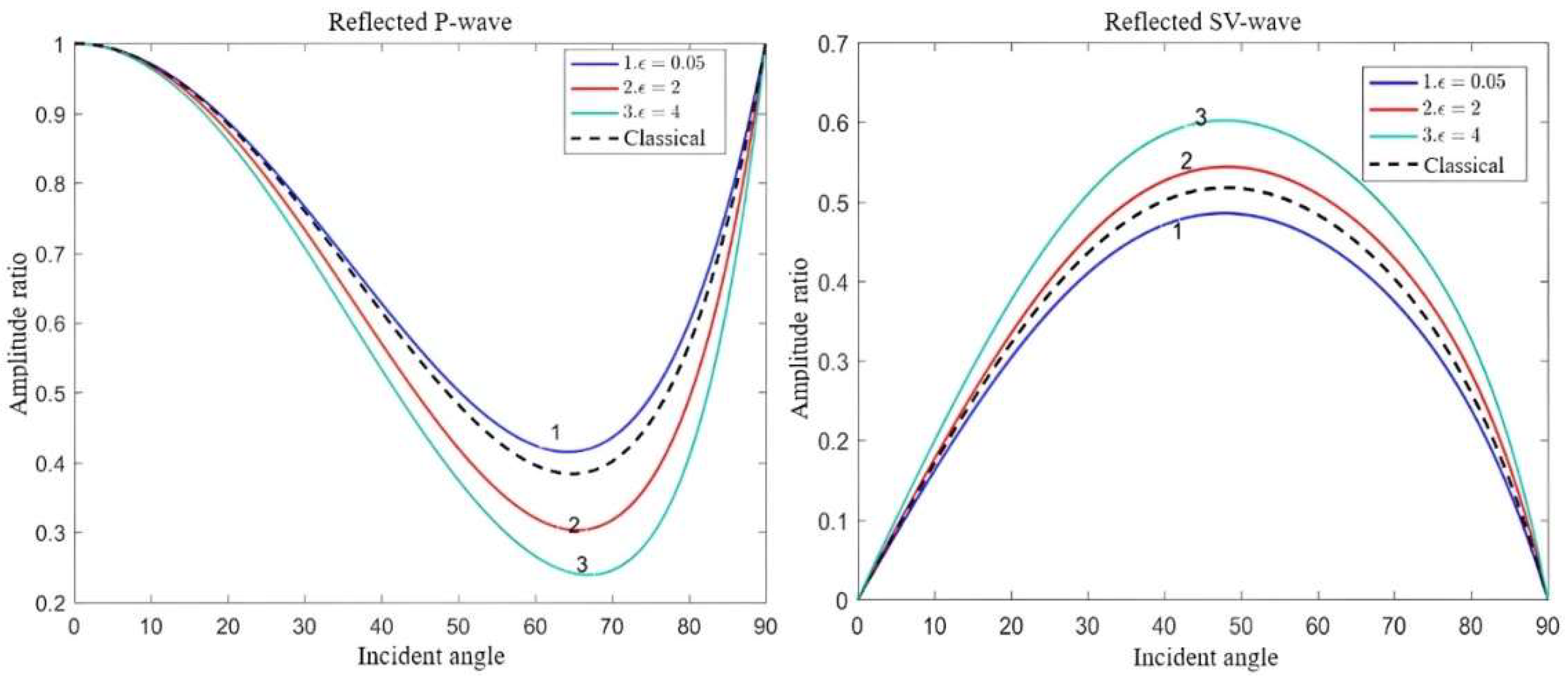
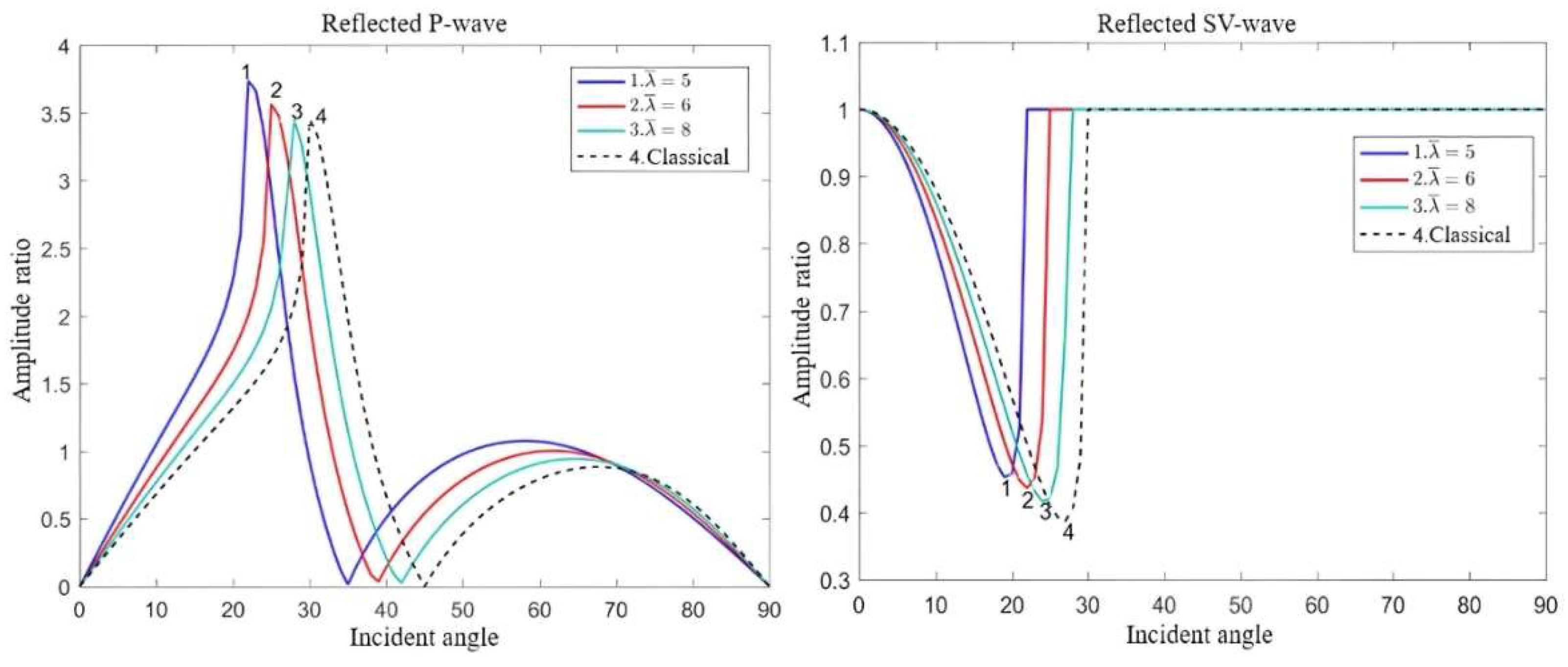
Figure 2 demonstrates the reflection coefficients of the body waves under different microstructural parameters when the P-wave is incident. For comparison with classical elastic waves, a reflection graph under the classical elastic condition is also presented. The results indicate that as the microstructural parameters increase, the reflection coefficient of the reflected P-wave gradually decreases, whereas that of the reflected SV wave gradually increases.
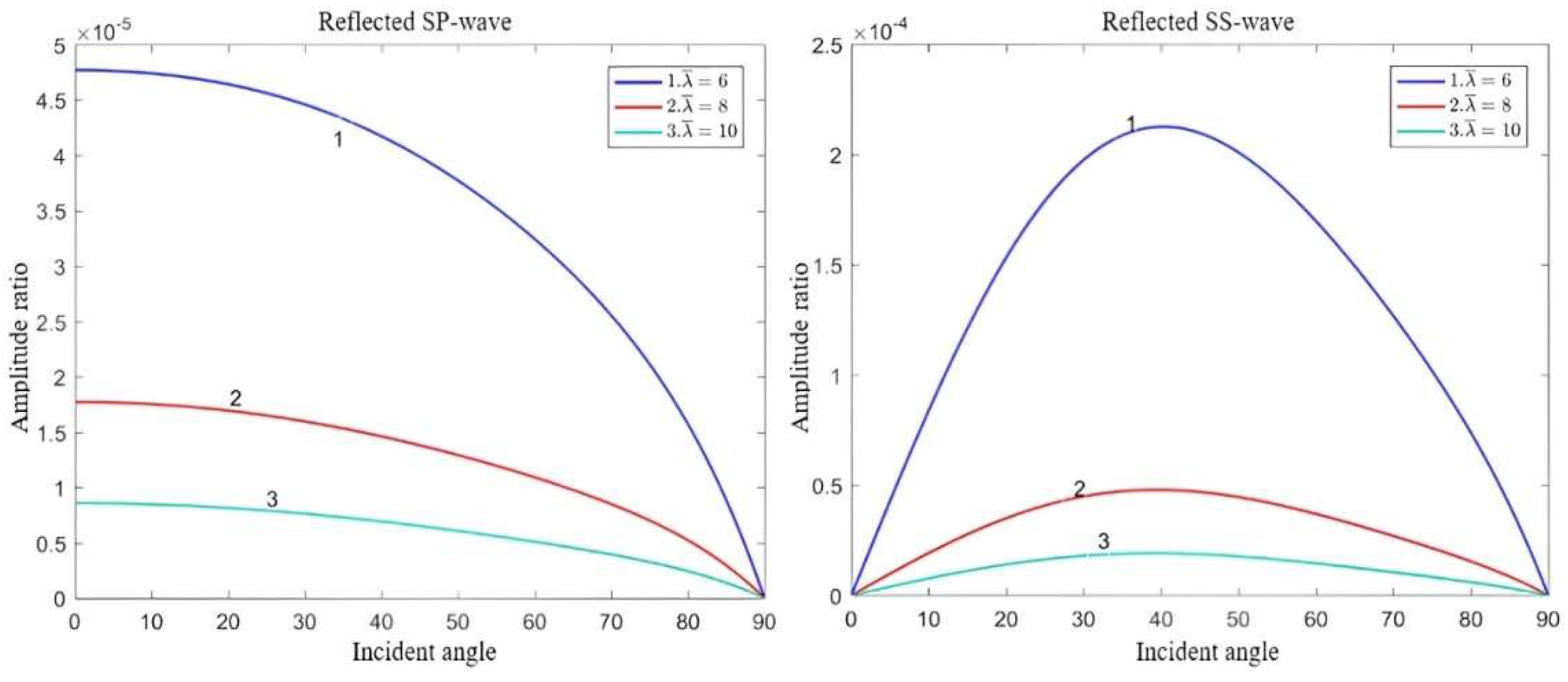
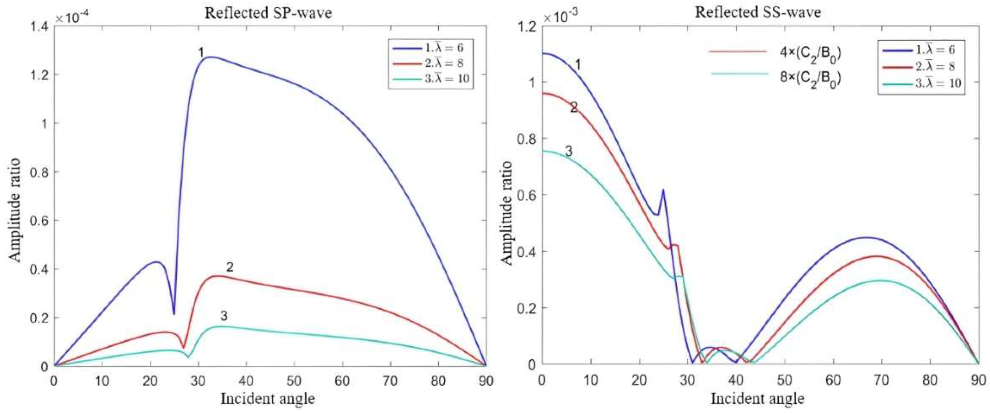
Figure 3 indicates the reflection coefficients of surface waves at different wavelengths, such as the reflected SP and SS waves, as shown in Figure 1. Compared with the reflected body waves, the reflection coefficient of the reflected surface waves decreased significantly with increasing wavelength.
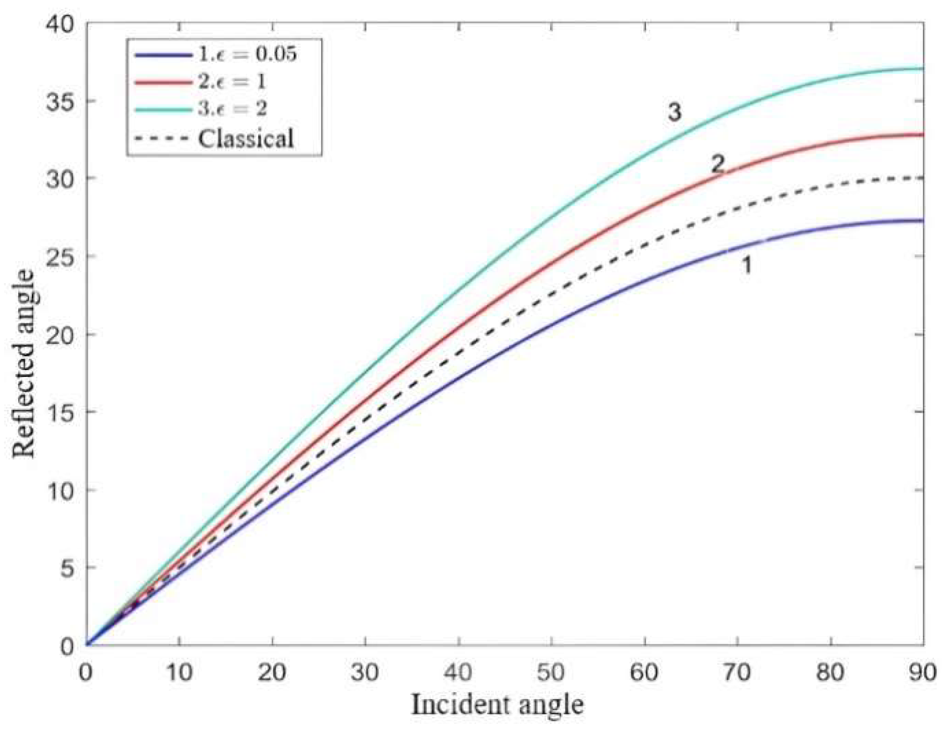
Figure 4 illustrates the variation in the reflection angle with the incident angle for different microstructural parameters. In classical elastic solids, the reflection angle reaches 90 degrees, and the incident angle is 30 degrees. These findings strongly suggest that, as the microstructure size increases, the reflection angle increases proportionally.
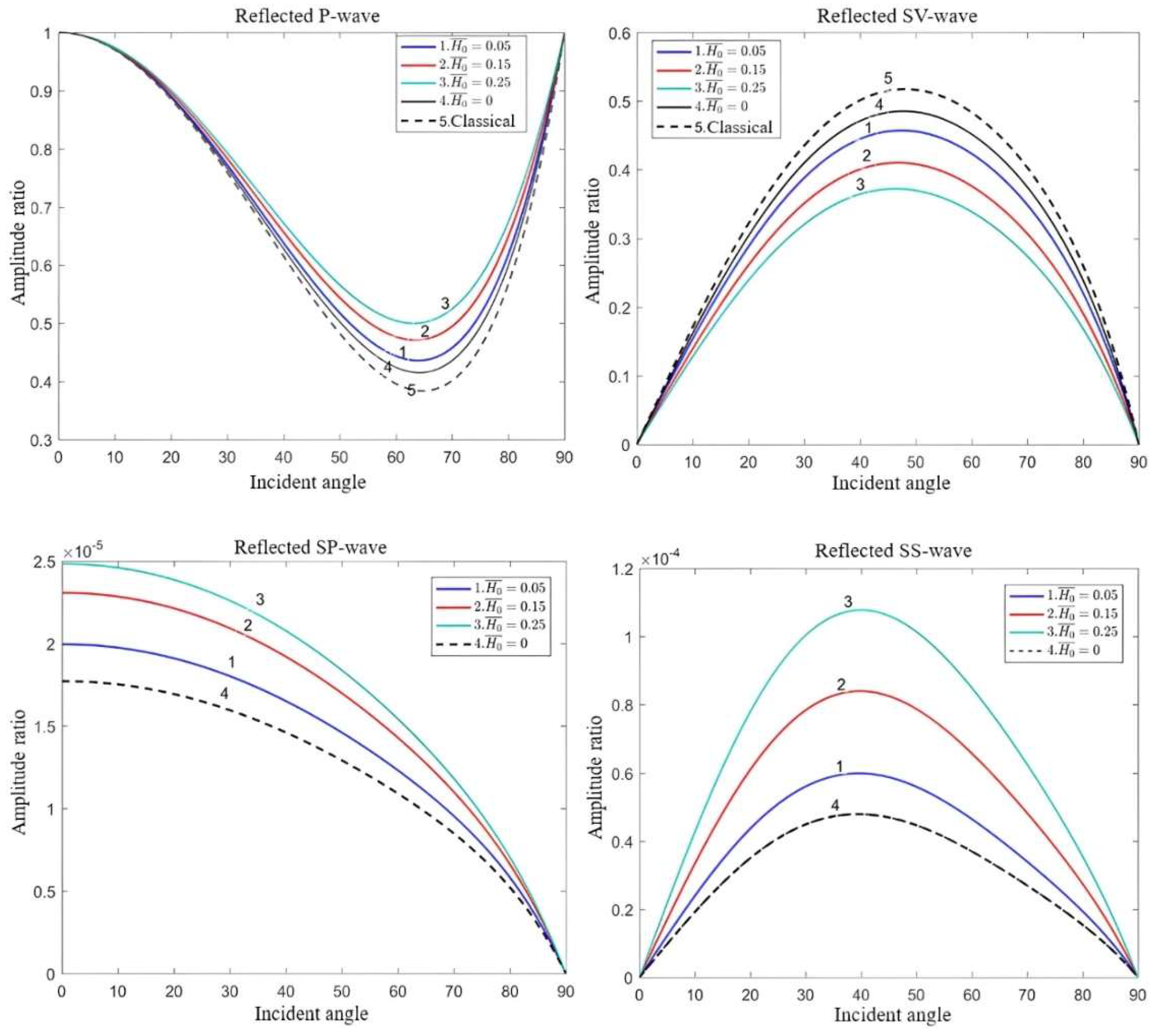
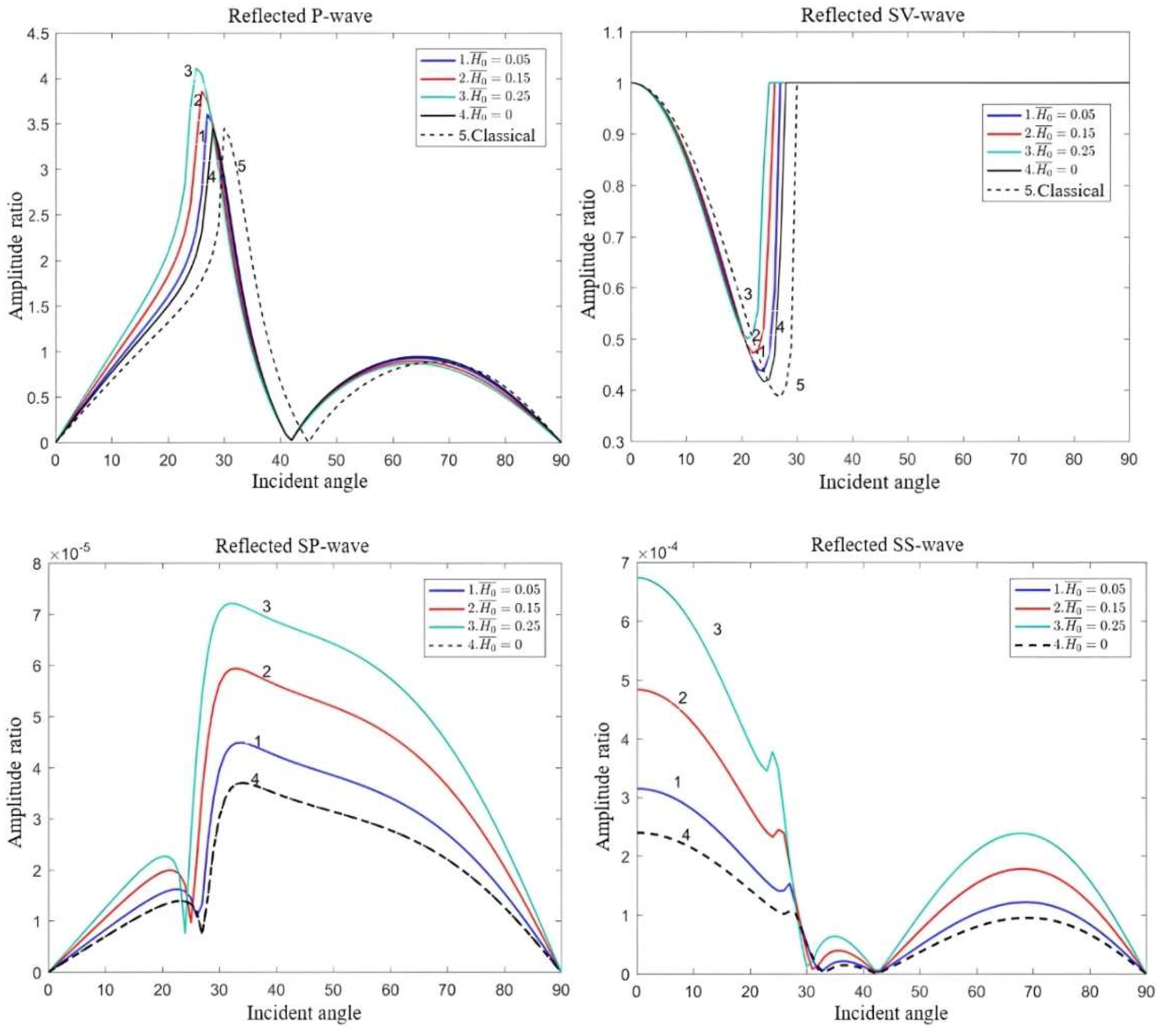
Figure 5 presents the reflection coefficients of the different waves under various external magnetic field intensities. The reflection coefficients under these conditions are also provided to facilitate a comparison with the cases of classical elasticity and no external magnetic field. The results indicate that the reflection amplitude ratio of the reflected SV wave decreases with an increase in H0, whereas the reflection amplitude ratios of the reflected P wave, reflected SP wave, and reflected SS wave all exhibit an increasing trend with an increase in H0. Furthermore, compared with the reflected body waves, the reflected surface waves (i.e., the reflected SP wave and reflected SS wave) show a significant increase with an increase in the external magnetic field. These findings suggest that reflection surface waves are more sensitive to variations in the external magnetic field than body waves.

4.2. Case of SV Wave Incidence

Figure 6 shows the reflection coefficients for different wavelengths. Compared with the classical scenario, the results reveal a decrease in the reflection coefficients as the wavelength increases. Notably, surface waves exhibit a higher sensitivity to changes in the wavelength than body waves, and the impact of the microstructural effect on elastic waves gradually diminishes.
Figure 7 displays the reflection coefficients for different applied magnetic fields. The reflected SV wave exhibited a decreasing trend in the reflection amplitude ratio with an increase in H0. In contrast, the reflected P, SP, and SS waves all demonstrate an increasing trend in the reflection amplitude ratio with an increase in H0. Compared with the microstructure, the applied magnetic field only causes numerical variations without altering the dispersion characteristics of the waves.
Figure 8 illustrates the influence of different microstructural parameters on the critical angle. In classical elastic solids, the interface produces a critical angle when the incident angle reaches 30 degrees. The results indicate that the microstructural parameters can cause a decrease in the numerical value of the critical angle. As the microstructural parameters increase, the critical angle also increases.

5. Conclusions

This paper primarily investigates the reflection of elastic waves by considering the influence of the microstructural effect and applied magnetic field. Through rigorous theoretical analysis, formula derivation, and numerical simulations, the following key conclusions were drawn:
(1)
In classical elastic solids, the reflected waves consist solely of P and SV waves. In dipole strain gradient elastic solids, the reflection phenomenon becomes more complex, and there are two types of inflected waves involving both body waves and surface waves: reflected P-waves, the reflected SV waves, the reflected SP waves, and the reflected SS waves.
(2)
Both the microstructural effect and Lorentz force affect the propagation of elastic waves. Notably, the impact of the magnetic field intensity and microstructural effects on surface waves surpasses that of body waves.
(3)
A critical angle arises when the SV wave is incident, and intriguingly, the critical angle increases proportionally with the augmentation of microstructural parameters.
(4)
In the classical scenario, elastic waves exhibit non-dispersive propagation characteristics. However, in dipolar gradient elastic solids, the introduction of the microstructural effect results in the emergence of novel wave modes and the manifestation of dispersion properties in elastic waves. Conversely, the applied magnetic field solely affects the amplitude of the elastic wave propagation through the influence of the Lorentz force without producing new wave modes or altering the dispersion characteristics of the elastic waves.

Author Contributions

Conceptualization, W.P. and T.W.; methodology, Z.W.; validation, C.Z., R.Z. and Y.G.; formal analysis, Z.W.; investigation, Y.J.; data curation, Y.J.; writing—original draft preparation, T.W.; writing—review and editing, W.P.; supervision, C.Z.; project administration, R.Z.; funding acquisition, Y.G. and R.Z. All authors have read and agreed to the published version of the manuscript.

Funding

This research was funded by the Sichuan Science and Technology Program (No. 2022YFG0274) and the National Natural Science Foundation of China (Grant No. 51875146).

Institutional Review Board Statement

Not applicable.

Informed Consent Statement

Not applicable.

Data Availability Statement

The authors confirm that data supporting the findings of this study are available within the article.

Conflicts of Interest

The authors declare no conflict of interest.

Appendix A

In Equation (33), the expressions for the elements of matrices A = ( a i j ) 8 × 8 ,   b = ( b i j ) 8 × 1 , and c = ( c i j ) 8 × 1 are as follows:
a 11 = i ξ , a 12 = i ξ , a 13 = i β s 1 , a 14 = γ s 1 , a 15 = i ξ , a 16 = i ξ , a 17 = i β s 2 , a 18 = γ s 2 ,
a 21 = i β p 1 , a 22 = γ p 1 , a 23 = i ξ , a 24 = i ξ , a 25 = i β p 2 , a 26 = γ p 2 , a 27 = i ξ , a 28 = i ξ
a 31 = ξ β p 1 , a 32 = i ξ γ p 1 , a 33 = β s 1 2 , a 34 = γ s 1 2 , a 35 = ξ β p 2 , a 36 = i ξ γ p 2 ,
a 37 = β s 2 2 , a 38 = γ s 2 2 , a 41 = β p 1 2 , a 42 = γ p 1 2 , a 43 = ξ β s 1 , a 44 = i ξ γ s 1 , a 45 = β p 2 2 ,
a 46 = γ p 2 2 , a 47 = ξ β s 2 , a 48 = i ξ γ s 2 , a 51 = μ 1 [ 2 + m s 1 2 c 1 ( 2 σ p 1 2 + ξ 2 ) ] ξ β p 1 ,
a 52 = μ 1 [ 2 + m s 1 + 2 c 1 ( 2 τ p 1 2 ξ 2 ) ] i ξ γ p 1 ,
a 53 = μ 1 [ ( ξ 2 β s 1 2 ) + m s 1 β s 1 2 c 1 ( σ s 1 4 2 ξ 2 ) ] ,
a 54 = μ 1 [ ( ξ 2 + γ s 1 2 ) m s 1 γ s 1 2 c 1 ( τ s 1 4 2 ξ 4 ) ] ,
a 55 = μ 2 [ 2 m s 2 + 2 c 2 ( 2 σ p 2 2 + ξ 2 ) ] ξ β p 2 ,
a 56 = μ 2 [ 2 m s 2 2 c 2 ( 2 τ p 2 2 ξ 2 ) ] i ξ γ p 2 ,
a 57 = μ 2 [ ( ξ 2 β s 2 2 ) + m s 2 β s 2 2 c 2 ( σ s 2 4 2 ξ 4 ) ] ,
a 58 = μ 2 [ ( ξ 2 + γ s 2 2 ) m s 2 γ s 2 2 c 2 ( τ s 2 4 2 ξ 4 ) ] ,
a 61 = μ 1 [ 2 ( σ p 1 2 + β p 1 2 ) + m s 1 β p 1 2 2 c 1 ( 2 σ p 1 4 ξ 4 ) ] ,
a 62 = μ 1 [ 2 ( 2 τ p 1 2 + ξ 2 ) m s 1 γ p 1 2 2 c 1 ( 2 τ p 1 4 ξ 4 ) ] ,
a 63 = μ 1 [ 2 m s 1 + c 1 ( σ s 1 2 + 2 ξ 2 ) ] ξ β s 1 , a 64 = μ 1 [ 2 m s 1 c 1 ( τ s 1 2 2 ξ 2 ) ] i ξ γ s 1 ,
a 65 = μ 2 [ 2 ( σ p 2 2 + β p 2 2 ) + m s 2 β p 2 2 2 c 2 ( 2 σ p 2 4 ξ 4 ) ] ,
a 66 = μ 2 [ 2 ( 2 τ p 2 2 + ξ 2 ) m s 2 γ p 2 2 2 c 2 ( 2 τ p 2 4 ξ 4 ) ] ,
a 67 = μ 2 [ 2 + m s 2 c 2 ( σ s 2 2 + 2 ξ 2 ) ] ξ β s 2 ,
a 68 = μ 2 [ 2 + m s 2 + c 2 ( τ s 2 2 2 ξ 2 ) ] i ξ γ s 2 ,
a 71 = 2 μ 1 c 1 ξ β p 1 2 i , a 72 = 2 μ 1 c 1 ξ γ p 1 2 i , a 73 = ( ξ 2 β s 1 2 ) μ 1 c 1 β s 1 i ,
a 74 = ( ξ 2 + γ s 1 2 ) μ 1 c 1 γ s 1 , a 75 = 2 μ 2 c 2 ξ β p 2 2 i ,
a 76 = 2 μ 2 c 2 ξ γ p 2 2 i , a 77 = ( ξ 2 β s 2 2 ) μ 2 c 2 β s 2 i ,
a 78 = ( ξ 2 + γ s 2 2 ) μ 2 c 2 γ s 2 , a 81 = 2 μ 1 c 1 β p 1 i ( σ p 1 2 + β p 1 2 ) ,
a 82 = 2 μ 1 c 1 γ p 1 ( 2 τ p 1 2 + ξ 2 ) , a 83 = 2 μ 1 c 1 ξ β s 1 2 i ,
a 84 = 2 μ 1 c 1 ξ γ s 1 2 i , a 85 = 2 μ 2 c 2 β p 2 i ( σ p 2 2 + β p 2 2 ) ,
a 86 = 2 μ 2 c 2 γ p 2 ( 2 τ p 2 2 + ξ 2 ) , a 87 = 2 μ 2 c 2 ξ β s 2 2 i , a 88 = 2 μ 2 c 2 ξ γ s 2 2 i ,
b 11 = i ξ ,   b 21 = i β p 1 , b 31 = ξ β p 1 , b 41 = β p 1 2 ,
b 51 = μ 1 [ 2 m s 1 + 2 c 1 ( 2 σ p 1 2 + ξ 1 2 ) ] ξ β p 1 ,
b 61 = μ 1 [ 2 ( σ p 1 2 + β p 1 2 ) m s 1 β p 1 2 + 2 c 1 ( 2 σ p 1 4 ξ 4 ) ] ,
b 71 = 2 μ 1 c 1 i ξ β p 1 2 , b 81 = 2 μ 1 c 1 i β p 1 ( σ p 1 2 + β p 1 2 ) ,
c 11 = i β s 1 , c 21 = i ξ , c 31 = β s 1 2 , c 41 = ξ β s 1 ,
c 51 = μ 1 [ ( ξ 2 β s 1 2 ) + m s 1 β s 1 2 c 1 ( σ s 1 4 2 ξ 4 ) ] ,
c 61 = μ 1 [ 2 + m s 1 c 1 ( σ s 1 2 + 2 ξ 2 ) ] ξ β s 1 , c 71 = c 1 μ 1 i β s 1 ( ξ 2 β s 1 2 ) , c 81 = c 1 μ 1 i ξ β s 1 2 .

References

  1. Eringen, A.C. Nonlocal Continuum Field Theories; Springer: Berlin/Heidelberg, Germany, 2001. [Google Scholar]
  2. Soroosh, H.; Glenn, R.H. Micropolar elasticity theory: A survey of linear isotropic equations, representative notations, and experimental investigations. Math. Mech. Solids 2017, 22, 224–242. [Google Scholar]
  3. Sun, Q.Y. Study of the Propagation Characteristics of Micropolar Elastic Wave in Layered Media. Doctoral Dissertation, University of Science and Technology of He’nan, Luoyang, China, 2012. [Google Scholar]
  4. Ma, X. Even Stress/Strain Gradient Theory and Its Hybrid Stress Meta-Analysis. Doctoral Dissertation, Dalian University of Technology, Dalian, China, 2014. [Google Scholar]
  5. Dai, A.M. A brief review of generalized continuum field theory. Mech. Prog. 1983, 13, 432–445. [Google Scholar]
  6. Dai, A.M. Current status and prospects of the generalized continuum field theory. Mech. Prog. 1999, 29, 1–8. [Google Scholar]
  7. Mindlin, R.D. Micro-structure in linear elasticity. Arch. Ration. Mech. Anal. 1964, 16, 51–77. [Google Scholar] [CrossRef]
  8. Georgiadis, H.G. The Mode III Crack Problem in microstructured solids governed by dipolar gradient elasticity: Static and dynamic analysis. ASME J. Appl. Mech. 2003, 70, 517–530. [Google Scholar] [CrossRef]
  9. Georgiadis, H.G.; Vardoulakis, I.; Velgaki, E.G. Dispersive rayleigh-wave propagation in microstructured solids characterized by dipolar gradient elasticity. J. Elast. 2004, 74, 17–45. [Google Scholar] [CrossRef]
  10. Gourgiotis, P.A.; Georgiadis, H.G.; Neocleous, I. On the reflection of waves in half-spaces of microstructured materials governed by dipolar gradient elasticity. Wave Motion 2013, 50, 437–455. [Google Scholar] [CrossRef]
  11. Li, Y.Q.; Wei, P.J. Elastic wave reflection and transmission of sandwich structures containing strain gradient material interlayer. In Proceedings of the China Mechanics Conference-2015, Shanghai, China, 11 August 2015; Chinese Mechanics Society: Beijing, China; Shanghai Jiao Tong University: Shanghai, China, 2015; p. 187. [Google Scholar]
  12. Li, Y.Q.; Wei, P.J.; Zhou, Y.H. Band gaps of elastic waves in 1-D phononic crystal with dipolar gradient elasticity. Acta Mech. 2016, 227, 1005–1023. [Google Scholar] [CrossRef]
  13. Li, Y.Q.; Wei, P.J. Reflection and transmission of thermo-elastic waves without energy dissipation at the interface of two dipolar gradient elastic solids. J. Acoust. Soc. Am. 2018, 143, 550–562. [Google Scholar] [CrossRef]
  14. Li, Y.Q. Study of Elastic Wave Propagation Based on Dipole Strain Gradient. Theory. Thesis, University of Science and Technology Beijing, Beijing, China, 2016. [Google Scholar]
  15. Li, Y.Q.; Wei, P.J. Reflection and transmission of plane waves at the interface between two different dipolar gradient elastic half-spaces. Int. J. Solids Struct. 2015, 56–57, 194–208. [Google Scholar] [CrossRef]
  16. Huang, Y.S.; Wei, P.J.; Xu, Y.Q.; Li, Y.Q. Modelling flexural wave propagation by the nonlocal strain gradient elasticity with fractional derivatives. Math. Mech. Solids 2021, 26, 1538–1562. [Google Scholar] [CrossRef]
  17. Li, Y.Q.; Wei, P.J.; Zhang, P.; Gao, X.W. Thermoelastic wave and thermal shock based on dipolar gradient elasticity and fractional-order generalized thermoelasticity. Waves Random Complex Media 2021, 1–26. [Google Scholar] [CrossRef]
  18. Dunkin, J.W.; Eringen, A.C. On the propagation of waves in an electromagnetic elastic solid. Int. J. Eng. Sci. 1963, 1, 461–495. [Google Scholar] [CrossRef]
  19. Yu, C.P.; Tang, S. Magneto-elastic waves in initially stressed conductors. Z. Angew. Math. Phys. ZAMP 1966, 17, 766–775. [Google Scholar] [CrossRef]
  20. Sharma, J.N.; Chand, D. Transient generalised magnetothermoelastic waves in a half-space. Int. J. Eng. Sci. 1988, 26, 951–958. [Google Scholar] [CrossRef]
  21. Roychoudhuri, S.K.; Santwana, B. Magneto-thermoelastic waves induced by a thermal shock in a finitely conducting elastic half space. Int. J. Math. Math. Sci. 1996, 19, 131–144. [Google Scholar] [CrossRef]
  22. Chattopadhyay, A.; Choudhury, S. Propagation, reflection and transmission of magnetoelastic shear waves in a self-reinforced medium. Int. J. Eng. Sci. 1990, 28, 485–495. [Google Scholar] [CrossRef]
  23. Singh, P.; Chattopadhyay, A.; Singh, A.K. Propagation of Love-type wave in functionally graded pre-stressed magneto-visco-elastic fiber-reinforced composite structure. Waves Random Complex Media 2021, 31, 942–971. [Google Scholar] [CrossRef]
  24. Pan, E.; Heyliger, P.R. Free vibrations of simply supported and multilayered magneto-electro-elastic plates. J. Sound Vib. 2002, 252, 429–442. [Google Scholar] [CrossRef]
  25. Buchann, G.R. Free vibration of an infinite magneto-electro-elastic cylinder. J. Sound Vib. 2003, 268, 413–426. [Google Scholar] [CrossRef]
  26. Wang, J.; Chen, L.; Fang, S. State vector approach to analysis of multilayered magneto-electro-elastic plates. Int. J. Solids Struct. 2003, 40, 1669–1680. [Google Scholar] [CrossRef]
  27. Othman, M.I.A.; Song, Y. The effect of rotation on the reflection of magneto-thermoelastic waves under thermoelasticity without energy dissipation. Acta Mech. 2006, 184, 189–204. [Google Scholar] [CrossRef]
  28. Othman, M.I.A. Generalized electro-magneto-thermoelasticity in case of thermal shock plane waves for a finite conducting half-space with two relaxation times. Mech. Mech. Eng. 2010, 14, 5–30. [Google Scholar]
  29. Othman MI, A.; Song, Y.Q. Reflection of magneto-thermoelastic waves with two relaxation times and temperature dependent elastic moduli. Appl. Math. Model. 2007, 32, 483–500. [Google Scholar] [CrossRef]
  30. Suchtelen, J.V. Product properties: A new application of composite materials. Philips Res. Rep. 1972, 27, 28–37. [Google Scholar]
  31. Chen, J.Y.; Chen, H.L.; Chen, L. Analysis of the Lamb wave propagation characteristics in the electromagnetic elastic plate. China Mech. Eng. 2007, 3, 328–330, 334. [Google Scholar]
  32. Chen, J.Y.; Chen, H.L. Reflection and transmission of elastic waves in a multilayer electromagnetic elastic structure. J. Basic Sci. Eng. 2008, 4, 566–573. [Google Scholar]
  33. Kumar, S.; Pal, P.C.; Majhi, S. Reflection and transmission of plane SH-waves through an anisotropic magnetoelastic layer sandwiched between two semi-infinite inhomogeneous viscoelastic half-spaces. Pure Appl. Geophys. 2015, 172, 2621–2634. [Google Scholar] [CrossRef]
  34. Kumar, S.; Pal, P.C.; Bose, S. Propagation of SH-type waves in inhomogeneous anisotropic layer overlying an anisotropic viscoelastic half-space. Int. J. Eng. Sci. Technol. 2014, 6, 24–30. [Google Scholar] [CrossRef]
  35. Ma, Y.B.; Liu, Z.Q.; He, T.H. Two-dimensional electromagneto-thermoelastic coupled problem under fractional order theory of thermoelasticity. J. Therm. Stress. 2018, 41, 645–657. [Google Scholar] [CrossRef]
  36. Kalkal, K.K.; Kumar, R.; Gunghas, A.; Deswal, S. Wave propagation in an initially stressed magneto-thermoelastic medium with voids and microtemperatures. J. Therm. Stress. 2020, 43, 962–980. [Google Scholar] [CrossRef]
  37. Kumar, A.Y. Reflection of plane waves from the free surface of a rotating orthotropic magneto-thermoelastic solid half-space with diffusion. J. Therm. Stress. 2021, 44, 86–106. [Google Scholar]
  38. Gunghas, A.; Sheoran, D.; Kumar, S.; Kalkal, K.K. Waves in a magneto-thermoelastic diffusive half-space with microconcentrations. Waves Random Complex Media 2022, 32, 708–727. [Google Scholar] [CrossRef]
  39. Li, Y.Q.; Bian, X.Y.; Wang, C.D.; Yue, T.; Guo, Z. The influences of external magnetic field on the reflection and transmission waves at the interface of two dipolar gradient elastic solids. Appl. Math. Model. 2023, 121, 524–541. [Google Scholar] [CrossRef]
Figure 1. Reflection of elastic waves.
Applsci 14 00376 g001
Figure 2. The influence of microstructural parameters on reflected body wave when P wave is incident ( λ ¯ = 8 ).
Applsci 14 00376 g002
Figure 3. The influence of wavelength on reflected body wave when P wave is incident ( ε = 0.05 ).
Applsci 14 00376 g003
Figure 4. The influence of microstructural parameters on reflection angle when P wave is incident ( λ ¯ = 8 ).
Applsci 14 00376 g004
Figure 5. The influence of applied magnetic field on the reflected wave when P wave is incident ( ε = 0.05 and λ ¯ = 8 ).
Applsci 14 00376 g005
Figure 6. The influence of the wavelength on the reflected wave when the SV wave is incident ( ε = 0.05 ).
Applsci 14 00376 g006aApplsci 14 00376 g006b
Figure 7. The influence of the applied magnetic field on the reflected wave when SV wave is incident ( ε = 0.05 and λ ¯ = 8 ).
Applsci 14 00376 g007
Figure 8. The influence of microstructural parameters on a critical angle when SV wave is incident ( λ ¯ = 8 ).
Applsci 14 00376 g008
Disclaimer/Publisher’s Note: The statements, opinions and data contained in all publications are solely those of the individual author(s) and contributor(s) and not of MDPI and/or the editor(s). MDPI and/or the editor(s) disclaim responsibility for any injury to people or property resulting from any ideas, methods, instructions or products referred to in the content.