Article

Numerical Study on the Flow Characteristics of High Attack Angle around the Submarine’s Vertical Plane

1
Department of Naval Architecture, Naval University of Engineering, Wuhan 430033, China
2
School of Naval Architecture, Ocean and Energy Power Engineering, Wuhan University of Technology, Wuhan 430033, China
*
Author to whom correspondence should be addressed.
Appl. Sci. 2024, 14(1), 395; https://doi.org/10.3390/app14010395
Submission received: 7 December 2023 / Revised: 28 December 2023 / Accepted: 30 December 2023 / Published: 31 December 2023
(This article belongs to the Section Marine Science and Engineering)

Abstract

:
When a submarine encounters an emergency situation, it should take emergency-surfacing actions by moving upward with a large angle of attack in the vertical plane. Previous research has often neglected the effect of vertical plane motion on the lateral force (Fy), rolling moment (Mx), and yawing moment (Mz). To examine the flow characteristics of submarines at high angles of attack on the vertical plane, the SST-DDES method is adopted in conjunction with adaptive mesh refinement (AMR) technology, and the new Omega vortex detection method is employed as the AMR criterion for numerical calculations. The obtained results are then appropriately verified by conducting water tank experiments, and the effects of different angles of attack and heel angles on Fy, Mx, and Mz are methodically examined. The results reveal that, in the flow around the vertical plane of a submarine, the influence of Fy and Mz cannot be ignored. In addition, when the vertical velocity of the hull is greater than 0.6 m/s, the influence of Mx cannot be overlooked either. When the angle of attack on the vertical plane of the submarine is greater than 25°, the effects of Fy, Mx, and Mz cannot be neglected, and the effect of Mz is particularly prominent, with its amplitude close to or greater than the average value of the pitch moment (My). The obtained results reveal that the presence of the heel angle (θ) intensifies the forces on the hull for Fy, Mx, and Mz, and the forces caused by the vertical velocity at Fy, Mx, and Mz cannot be neglected. These findings can provide a mechanical analysis basis for the analysis of nonlinear motion phenomena during submarine surfacing.

1. Introduction

In an emergency, submarines should take emergency-surfacing measures. During the plating process, but before breaking the water surface, excessive rolling, swaying, and yawing movements may occur. Schreur [1] documented the movements of floating circular cylinders rising vertically (no forward velocity), with and without simulated deck and appendage geometries. However, these experiments were performed at low Reynolds numbers. The findings revealed that the bare cylinders show unpredictable swaying and yawing motions due to unsteady vortex shedding in the wake. When vertical vanes were added on top of the cylinder, roll amplitudes ranging from 30° to 150° were observed. The free-running model experiments conducted by Itard [2] showed a 60° roll angle during the ascent process. Watt [3] conducted experiments on a full-scale diesel–electric submarine, which showed a lateral roll angle of 25° during emergency surfacing. However, it should be noted that this study did not consider the occurrence of very high flow, where the unsteady vortex shedding makes the maneuver inherently unpredictable. Bettle et al. [4] exploited a mathematical model based on quasi-steady state coefficients to examine the submarine surfacing problem. This study showed that the roll angle is very sensitive to the initial lateral inclination angle. When the initial bank angle was set as 2°, the roll angle during ascent reached 9°, whereas, in the absence of the initial roll angle, the roll angle during ascent was only 1.5°. Chen et al. [5] examined the effect of pitch angle, yaw angle, static stability height, and water flow holes on the translation roll angle of submarines through free surface model experiments. The obtained results indicated a positive correlation between the yawing moment and the roll angle and thereby concluded that limiting the yaw angle can reduce the roll angle. However, the intrinsic relationship between the yawing moment and the roll angle was not unanswered.
During the emergency-surfacing process, submarines accelerate their vertical ascent from low speeds at high angles of attack, inducing unsteady flow and generating asymmetric vortex flows around the hull. The resulting lateral force (Fy), yawing moment (Mz), and rolling moment (Mx) may be the primary causes of excessive rolling and swaying during submarine surfacing. However, current research on the high-angle-of-attack motion of submarines in the vertical plane generally considers only the effect of high angles of attack in the vertical plane. While Watt [6] considered high-angle-of-attack motion in developing quasi-steady state coefficients for the six-degrees-of-freedom equations of motion, the study overlooked the effect of submarine vertical plane motion on the horizontal plane forces and the rolling moment, only fitting the forces at various attack angles in a mean–value manner. Similarly, Liang et al. [7] conducted water tank experiments with a planar motion mechanism (PMM) in a circulating water channel (CWC) to revise the equations of motion associated with the high-angle-of-attack motion of a submarine vertical plane; however, the effects of the vertical plane motion on the horizontal plane forces and the rolling moment were not addressed.
In aerodynamics, research on lateral forces on symmetric bodies is more common at high angles of attack and is mainly applied to slender bodies. Sohail et al. [8] carried out a numerical simulation of the asymmetric phenomenon of slender bodies at high angles of attack via the separated vortex SA-DES approach and surface roughness application, which were suitably compared with the experimental results. Ma et al. [9] examined the unsteady characteristics of asymmetric vortices through experiments on narrow elliptical cones at angles of attack from 0 to 90° and velocities of 10 to 40 m/s. The performed study showed that, at angles of attack between 60° and 80°, vortex instability produces noticeable fluctuations in the lateral forces, with the peak-to-peak amplitude of cross-sectional lateral force coefficients reaching 2.0. Clainche et al. [10,11] performed numerical simulations and experimental investigations on a high angle of attack and low Reynolds number flow over a hemispherical nose cylinder using DNS and discussed the mechanism of vortex shedding. Of course, there are many factors that affect the lateral force on an object at large attack angles in aerodynamics, such as surface roughness. Paulo [12] investigated turbulent flows past a rough circular cylinder under the moving wall effect in the large-gap regime, while Han [13] explored the influence mechanism of surface roughness on a cylinder vortex-induced vibration (VIV) by introducing the modified model of rough wall velocity gradient. At this stage in our research, we mainly focus on the force mechanism of submarines under large attack angles. Therefore, the calculation object and physical model assumed in this paper are both in a smooth state.
Accurate capture of vortex shedding is a critical aspect of numerical calculations for a high angle of attack. The choice of the turbulence model and reasonable network design are two important factors. The detached eddy simulation (DES) represents a hybrid modeling method [14] that combines the advantages of Reynolds-averaged Navier–Stokes (RANS) and large eddy simulation (LES). The RANS methodology is commonly employed in the near-wall region to reduce the number of grids and computational resources, whereas the LES method is utilized in the far-wall region to effectively resolve the conflict between the calculation accuracy and the computational resources. Currently, it has been extensively implemented to analyze the relevant engineering-based problems. In 1997, Spalart et al. [15] proposed the SA-DES model based on the Spalart–Allmaras (SA) model. Subsequently, researchers gradually improved it and proposed the delayed discrete eddy simulation (DDES) model and the improved one (IDDES). In this regard, Wei-wen and De-Cheng [16] utilized the DES model to simulate the flow around tandem circular cylinders. Using the DES model, Nguyen and Nguyen [17] studied the vibration problem caused by the vortex of a cylinder at different speeds and mass ratios. Yao et al. [18] conducted a comparative study of the flow around a cylinder via the DDES approach and constrained LES models. Although the results of the constrained LES model were slightly better, its complexity was higher than that of the DDES model. Liu [19] compared different RANS and DDES models, simulated the static flow and forced oscillation of the NACA0015 airfoil at high angles of attack, and compared the results with experimental values. The obtained results revealed that the SST-DDES model is effectively capable of capturing the vortex shedding on the leeward side of the airfoil and the obtained unsteady aerodynamic loads were in reasonably good agreement with the experimental values, whereas the RANS methods did not perform well.
In numerical simulations, a proper mesh layout is another factor for accurate calculations, and adaptive mesh refinement (AMR) technology is an effective approach to adjust the accuracy of the solution in specific sensitive or turbulent simulation regions during the dynamic calculation process. AMR technology is capable of refining the mesh in certain regions during the numerical simulation process, leading to more accurate solution results. Currently, this technology has been increasingly adopted [20,21,22], but it requires reasonable adaptation criteria. Gou et al. [23] developed an LES refinement criterion that represents the ratio of modeled kinetic energy based on the basic hypothesis of the LES. This approach uses the LES simulation results to estimate the appropriate length scale of the LES grid for automatic refinement, arriving at better results. Mozaffari et al. [24] proposed an adaptive mesh criterion based on time-averaged quantities, producing meshes that are suitable for capturing the unsteady flow field at any instant and do not evolve rapidly over time.
The combined RANS-LES method adopted in this study is an improved delayed DES-based methodology derived from the classical DES method [25]. To this end, the shear stress transport (SST) k-ω two-equation turbulence model and its corresponding DDES version are employed. In combination with AMR technology, a novel method of omega vortex identification as an adaptive mesh criterion is introduced. In the first step, preliminary test calculations are performed on the flow around a cylinder. Subsequently, the method is applied to calculate the flow around the vertical plane of a submarine at high angles of attack and is validated on the basis of the experimental data. Finally, the influence of different angles of attack and rolling angles on the lateral force, rolling moment, and yawing moment of the submarine have been discussed and analyzed.

2. Materials and Methods

2.1. Development of a Model

A suitable submarine model entitled “NEU” and designed by the research team was employed as a test model, primarily to examine the mechanics of unconventional submarine motion. The origin of the body coordinate system was defined at the center of mass of the submarine using a left-handed coordinate system. The x-axis was aligned with the longitudinal axis of the submarine, while the positive y-axis pointed to the left of the submarine. A schematic representation of the body coordinate system model and definition has been presented in Figure 1. The NEU-based model consisted of a main hull, a conning tower sail, a rudder, and an “X” tail rudder with a length of L = 3 m and a diameter of DL = 0.3 m. Other initial parameters of the NEU-based model are listed in Table 1.

2.2. Numerical Approach

In the present investigation, simulation calculations were performed using the commercial fluid dynamics software STAR-CCM+ 13.05, which integrates AMR technology. To establish adaptive mesh criteria, a new omega vortex identification approach was introduced [26]. The SST-DDES model was employed as a coupled flow solver to solve the continuity and momentum conservation equations. The velocity field was obtained from the momentum equation, whereas the pressure field was calculated using the continuity equation. Further, the time step for the simulations was set as 0.001 s.

2.2.1. Governing Equation Viscous Flow

The RANS equation serves as the fundamental equation governing the kinematic and hydrodynamic aspects of viscous flow, encompassing primarily the continuity equation and momentum equation. The explicit formulations of these two equations are presented below:
t ρ m + ρ m v m = 0
t ρ u i + x j ρ u i u j = p x i + x j ρ u i u j ¯ + ρ f i + x j μ u i x j + u j x i 2 3 μ u l x l δ i j i ,
where ρ is the fluid density, μ is the fluid viscosity, p is the static pressure, fi is the mass force at unit, δij is the unit tensors, u i is the pulse of ui, and ui is the velocity component of x direction, respectively.

2.2.2. The SST-Based Model

The DDES hybrid method is constructed based on the traditional RANS turbulence model equations. In the present work, the SST k-ω turbulence model was employed, which was essentially formulated on the basis of the following two equations:
( ρ k ) t + ρ u j k x j = P β * ρ ω k + x j μ + σ k μ t k x j ( ρ ω ) t + ρ u j ω x j = ρ γ μ t P β * ρ ω 2 + x j μ + σ ω μ t ω x j + 2 1 F 1 ρ σ ω 2 ω k x j ω x j ,
where ρ represented the density, μj denoted the velocity vector, and xj signified the position vector. In addition, k and ω denoted the turbulence kinetic energy and the specific rate of dissipation, respectively, whereas μ and μt, in order, were the laminar and turbulent viscosity coefficients. The form of the production term P, the function F1, and the values of the coefficients β*, γ, σk, and σω2 can be found in the literature pertinent to the SST-based model [25].

2.2.3. Establishment of the DDES Model

The DDES model [27] reconstructs the length scale (lDDES) of the DDES model by introducing a delay function, which remarkably reduces the problem of modeled stress depletion (MSD) and its direct consequence, namely grid-induced separation (GIS). The DDES method was implemented in the hybrid RANS-LES-based approach of this study.
Similar to the DES method, replacing the length scale (lRANS) in the turbulence model with the length scale of DDES (lDDES) yields a DDES method based on the original turbulence model. The length scale (lDDES) can be expressed in the following form:
l D D E S = l R A N S f d max { 0 , l R A N S l L E S }
The delay function (fd) can be defined as follows:
f d = 1 tanh [ ( c d r d ) 3 ] ,
where cd = 8, and the parameter rd can be expressed by the following:
r d = ν + ν t u i , j u i , j κ 2 d 2 ,
where vt represents the turbulent viscosity coefficient, ui,j denotes the velocity gradient, κ = 0.41, and d signifies the distance from the wall.
The RANS length scale of the SST turbulence model (lRANS) is defined as follows:
l R A N S = k 1 / 2 β * ω
The length scale of the LES-based approach can be solely determined by the grid spacing:
l L E S = C D D E S Δ ,
where Δ represents the local grid spacing. Here, Δ is taken as the maximum length of the line connecting the centers of adjacent mesh cells, i.e., C D D E S = ( 1 F 1 ) C D D E S o u t e r + F 1 C D D E S i n n e r , where C D D E S o u t e r = 0.61, C D D E S i n n e r = 0.78, and F1 represents an internal function of the SST-based model.
According to the DDES model, it can be seen that as fd approaches zero, the RANS calculation can be adopted, while when fd approaches 1, it is transformed into the traditional DES method. This approach is capable of protecting the RANS calculation in the attached flow boundary layer without affecting the DES calculation in other regions.

2.2.4. Mesh Adaptation Criteria

When using the AMR technique, the mesh refinement level refers to the maximum number of times a mesh cell can be refined during the computation process. A refinement level of one for a volumetric mesh cell represents the division of a parent grid cell into eight sub-grid cells, as presented in Figure 2. Figure 2a illustrates an initial grid plane schematic within the yellow box, whereas Figure 2b–d correspond to refinement levels 1, 2, and 3, respectively, because the mesh was refined in that region. Herein, a refinement level 2 was applied to the continuum-based model.
Commonly, refining the grid and establishing adaptive grid criteria is a challenging task. When dealing with a high angle of attack flow around a submarine, complex phenomena, such as boundary layer separation and vortex shedding, come into play. Therefore, choosing the novel omega vortex identification method as the criterion for adaptive grid refinement could lead to better vortex capture, thereby enhancing the accuracy of the solution.
The novel omega vortex identification approach was first proposed by Liu et al. [26] in 2016. In contrast to conventional vortex identification methods, the new omega method has physical significance and normalization characteristics. It is able to simultaneously capture both strong and weak vortices, without the need for significant threshold adjustments. The new omega-based approach is mainly constructed based on the decomposition of the eddy field into its rotating component, denoted by R, and its non-rotating component, denoted by S, as in the following form:
ω = R + S
Typically, the directions of R and ω are dissimilar. By introducing the parameter Ω, which represents the ratio of the magnitude of the rotating vortex to the magnitude of the total vortex, the corresponding calculation formula is given by the following:
Ω = B 2 F A 2 F + B 2 F ,
where A and B represent the symmetric and antisymmetric tensors of the velocity gradient, which are expressed in Equations (9) and (10) as follows:
A = 1 2 ( V + V T ) = u x 1 2 ( u y + v x ) 1 2 ( u z + w x ) 1 2 ( u y + v x ) v y 1 2 ( v z + w y ) 1 2 ( u z + w x ) 1 2 ( v z + w y ) w z
B = 1 2 ( V V T ) = 0 1 2 ( u y v x ) 1 2 ( u z w x ) 1 2 ( v x u y ) 0 1 2 ( v z w y ) 1 2 ( w x u z ) 1 2 ( w y v z ) 0
It can be seen that the value range of Ω is between 0 and 1, which can be understood as the vorticity concentration. The expression Ω = 1 represents the case of fluid rotating with the cylinder, whereas Ω > 0.5 indicates that B is larger than A, and therefore, Ω slightly larger than 0.5 can be used as a vortex identification criterion. In practical applications, to avoid the problem of very large errors when the denominator of Equation (12) is a very small number, a small positive constant (ε) is added to the denominator. As a result, the expression Ω is modified to the following:
Ω = B 2 F A 2 F + B 2 F + ε
In this study, the value of ε was set to 0.001 based on the approximate expression suggested by Dong et al. [28], and Ω = 0.52 was selected as the threshold value for vortex identification. To control the number of grid points, certain constraints were imposed on the extent of the adaptive mesh in the hull computational domain. Specifically, only an area five times the hull width around the hull was refined.

2.2.5. Boundary Conditions and Grid

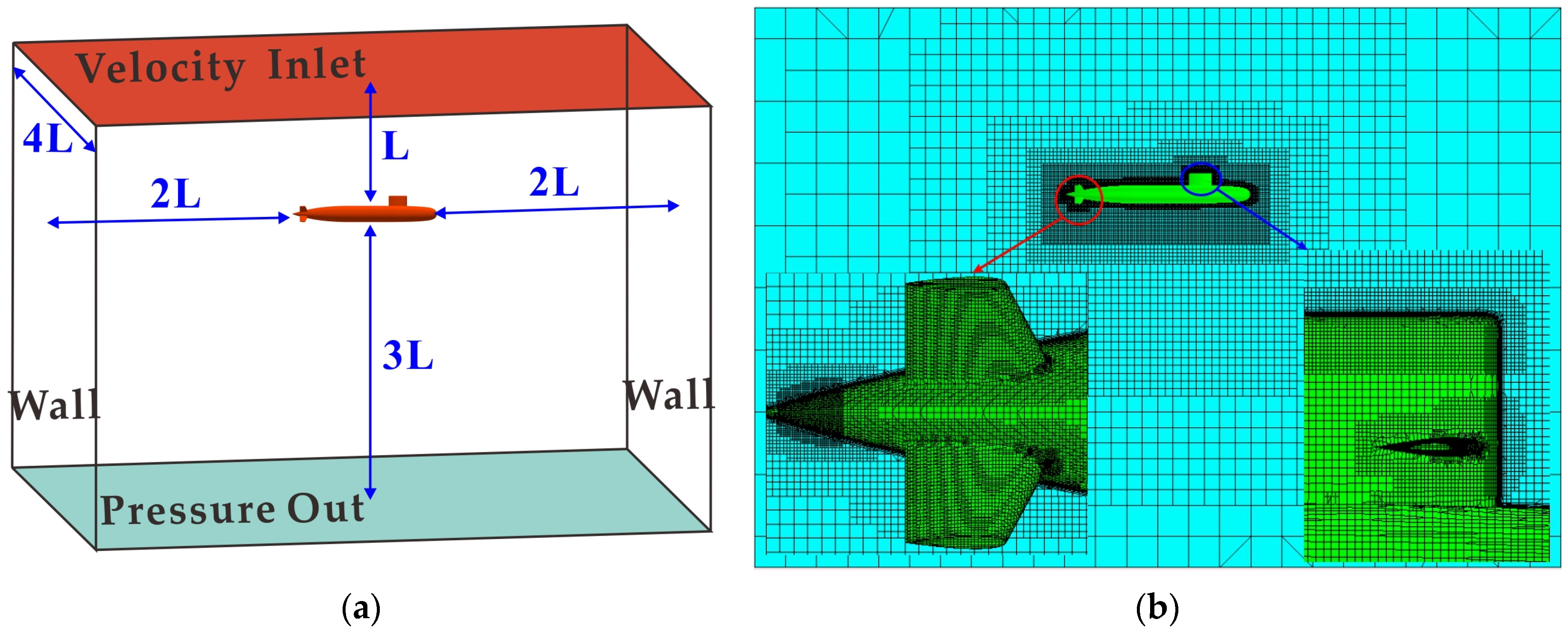
The accuracy of the numerical simulations strongly depends on the quality of the computational mesh. Choosing the right domain size has a significant impact on the accuracy of the solution and the computational cost. Figure 3 illustrates the computational domain and mesh structure for the vertical flow around the model. The upper surface of the computational domain acted as the inlet boundary with fluid velocity, located at a distance of L away from the hull, whereas the lower surface was the outlet boundary with fluid pressure, located at a distance of 3L from the hull. The left, right, front, and rear surfaces were considered solid walls, all of which were located at a distance of 2L from the hull.
The computational mesh adopted a shearing-type structure, with five mesh layers assigned to the hull boundary layer. The size of the first layer, y+, was approximately set as 1, and the mesh size of the hull body was considered to be 8 mm. The entire area around the hull was refined with a mesh size of 16 mm, while protruding areas, such as the hull and stern rudder, were locally refined with a mesh size of 16 mm. The initial number of meshes was taken as 1.06 million.

2.3. Experiment

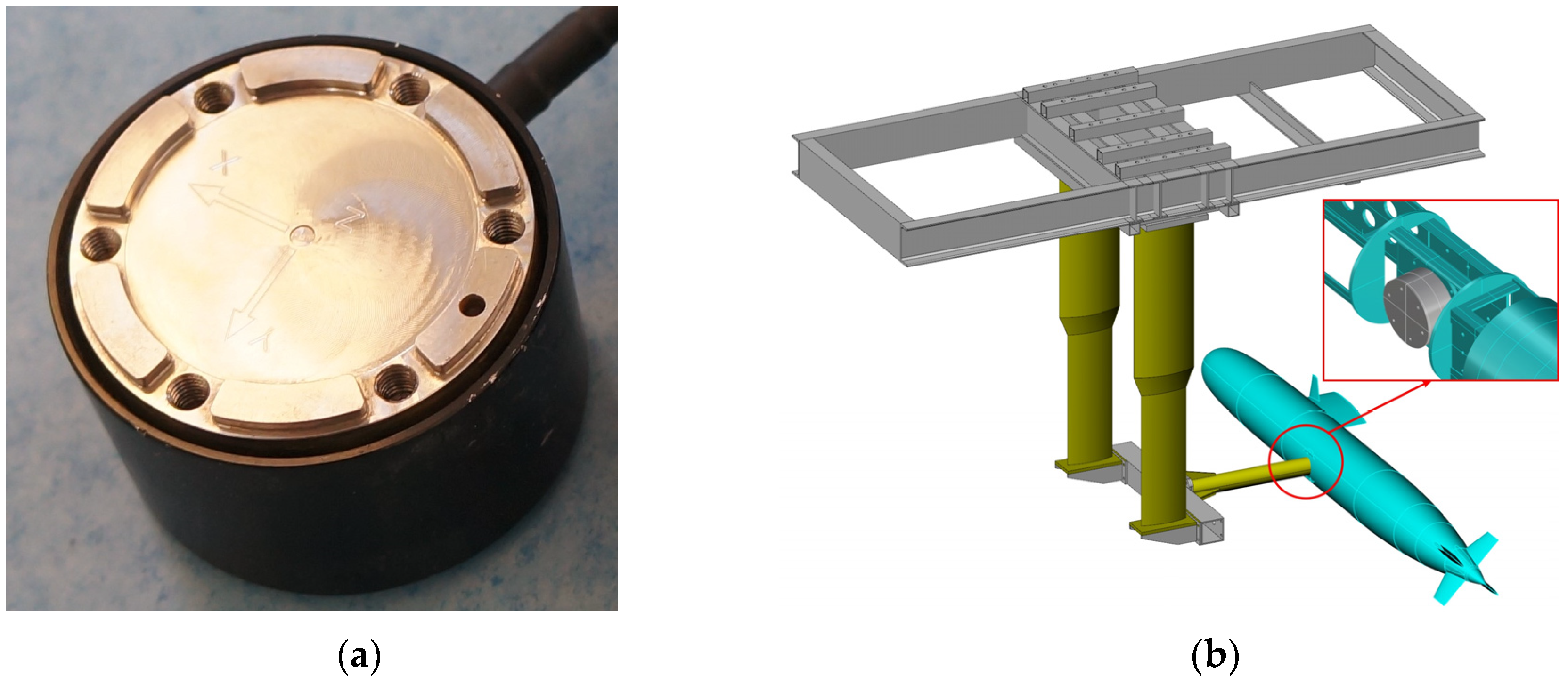
The vertical flow experiment was carried out in a towing tank with dimensions of 510 m long, 6.5 m wide, and 5 m water depth. Table 2 presents the performance parameters of the towing tank. Figure 4a illustrates the experimental setup, where the model was confined at a depth of 1.2 m underwater to reduce the influence of the free surface on the test results. A six-component force sensor was installed in the lower middle section of the hull’s bottom. The experimental speeds ranged from 0.5 m/s to 1.6 m/s, with specific values of 0.5, 0.8, 1.0, 1.2, 1.4, and 1.6 m/s. The support point was located at the center of gravity and the forces in the X, Y, and Z directions as well as the moments around the X, Y, and Z axes, which were measured using a six-component force sensor.
The setup configuration for the vertical flow test is depicted in Figure 4b. This model was vertically supported by twin fins that provided good stability. One side of the twin fins was connected to the fixed frame of the trailer and the other side to the horizontal support structure of the hull. To minimize the impact of the experimental apparatus on the flow field around the hull, the horizontal support structure was fixed to the hull at a single point using circular pipe fittings at a single point. The underwater six-component balance was fixed at an internal support point of the model, and its installation coordinate system was aligned with the hull’s coordinate system. Figure 5 provides a schematic representation of the six-component force sensor and its installation positions.

3. Validation of the Proposed Numerical Methods

In order to validate the effectiveness of the numerical calculation method, before conducting the experiments, it was deemed necessary to consider the similarities between the vertical flow around a submarine and the flow around a cylinder. In addition, there exists a considerable amount of publicly available experimental data for flow around a cylinder, which facilitates the validation process. Therefore, the initial experiment consisted of simulating the flow around a cylinder, followed by simulating the vertical flow around the submarine and further validating the results through a comparison with the experimental data.

3.1. Preliminary Tests

The flow around a cylinder problem was chosen for calculation at Re = 3900, with a cylinder diameter D = 0.01 m. Figure 6 illustrates the computational domain and grid layout for the flow around the cylinder. The cylinder was located 10D away from the fluid inlet surface, 30D away from the pressure outlet surface, and 10D away from both the left and right sides. The height of the cylinder corresponded to the height of the computational domain. The grid size on the surface of the cylinder was 0.1 mm, with local refinement in the vicinity of the cylinder using a size of 0.4 mm. This mesh was further refined in the 5D domain downstream of the cylinder, with a refinement size of 0.8 mm. The initial grid consisted of 0.8 million cells, with adaptive refinement applied to the 5D downstream range of the cylinder.
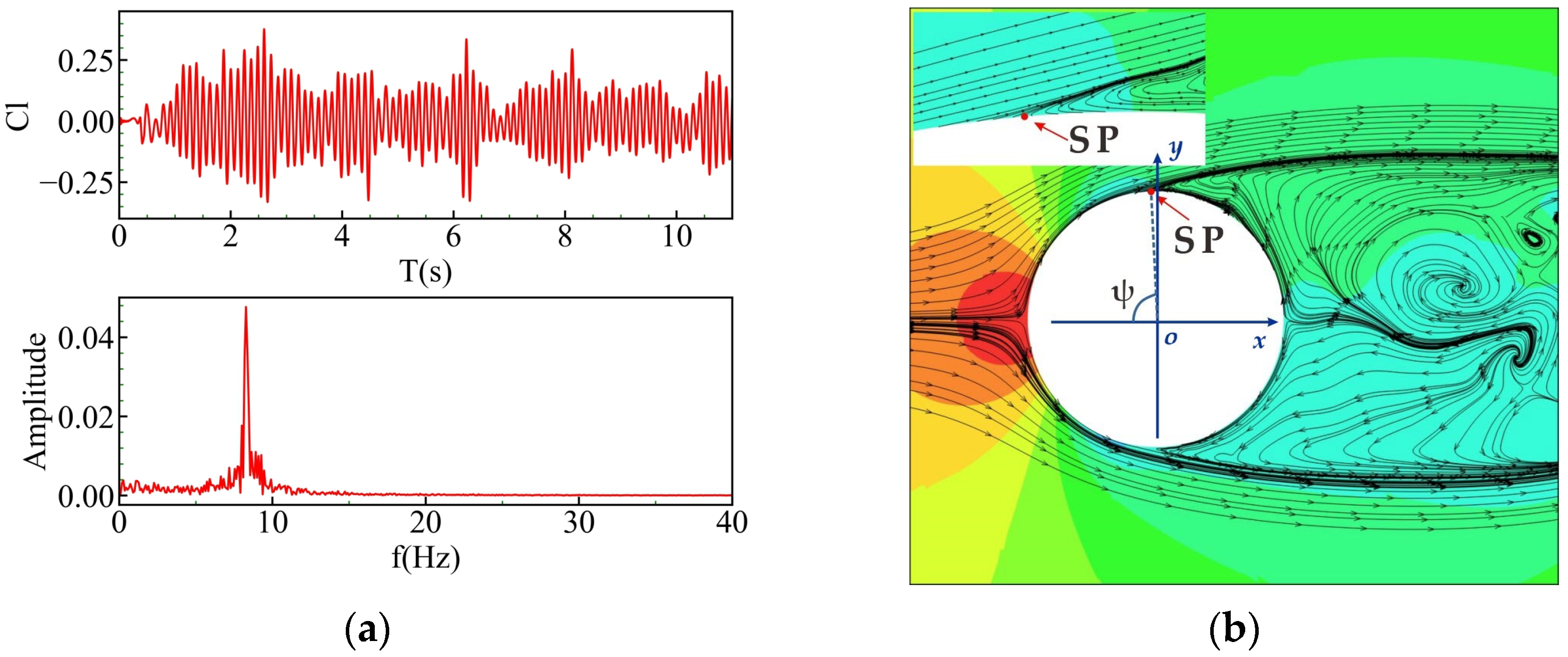
The computational results of the typical parameters for the flow around a cylinder as well as the experimental results [29] are presented in Table 3. The typical factors include the Strouhal number (St), separation angle (ψ), and minimum flow velocity along the centerline of the wake (Umin). It can be seen that the calculated values of the typical parameters for the flow around the cylinder using the SST-DDES model show small deviations from the experimental results, with errors of 1.43%, 1.39%, and 8.24% for St, ψ, and Umin, respectively. Figure 7 presents the lift and spectrum plots as well as a schematic representation of the separation angle, where Sp signifies the separation point.
Figure 8 displays the Cp curve for the average pressure coefficient on the cylinder surface, with a general trend that matches the experimental results. The calculated values almost agree with the experimental results, with an error of only 2.24% observed for the point with the minimum Cp value of −1.133, compared to the experimental value of −1.159.
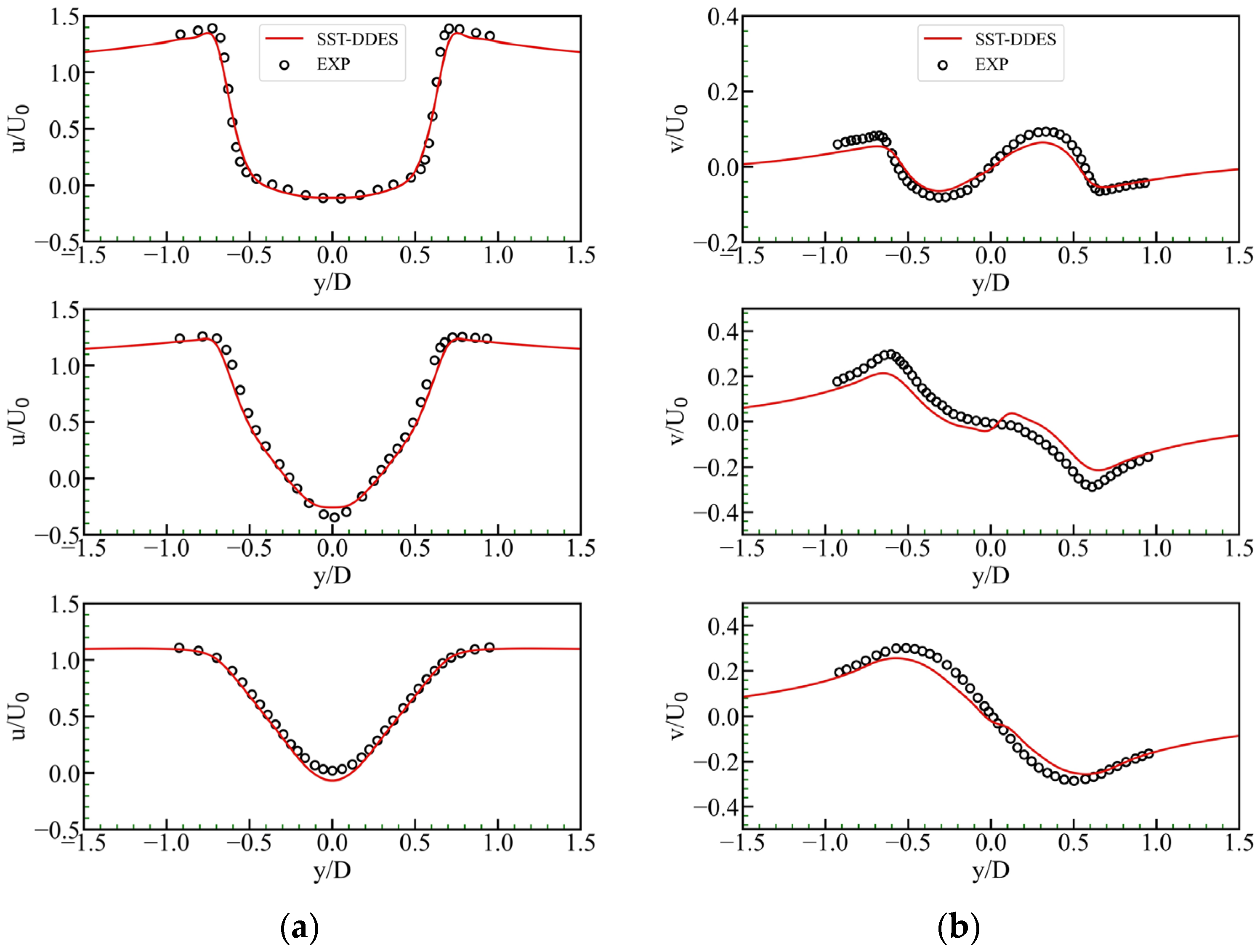
A further analysis of the wake velocity field was performed by comparing and analyzing the obtained results for three cross-sections at x/D = 1.06, 1.54, and 2.02 in the wake of the cylinder. Figure 9 demonstrates a comparison between the average velocity profiles in these three cross-section positions and the experimental results. Figure 9a illustrates the average velocity profiles of the x-direction at three positions. The average velocity distributions for all three cross-sections exhibit axially symmetric curves. The velocity distribution at section x/D = 1.06 follows a U-shaped profile about the y/D axis, while the other two sections exhibit a V-shape, which is in good agreement with the experimental results. Figure 9b displays the average velocity profiles of the y-direction at three cross-section positions. The plotted results reveal that the average velocity distributions for all three sections demonstrate centrally symmetric curves. Furthermore, there are differences in the results of section x/D = 1.54, but overall, the pertinent results are almost consistent with the experimental results.
Figure 10 displays grid plots at various time instants, representing the idea that adopting the new omega criterion methodology allows for capturing the vortices, thereby leading to a more rational grid distribution. Throughout the calculation process, the maximum number of grids reached about four million. It took 12 h to compute it on the server, utilizing three blades, with each blade having 128 GB of memory and 20 cores.
By comprehensively comparing the calculation results of typical parameters, Cp curves, and wake velocity fields with experimental data, it is obvious that the implementation of the SST-DDES method combined with AMR technology is capable of accurately simulating the flow around a cylinder.

3.2. Experimental Results of the Flow around a Vertical Plane

In the experimental study of the submarine flow around a vertical plane, data sampling was performed at a frequency of 20 Hz. Considering the asymmetry of the submarine’s hull in the yoz plane, the main forces acting on the submarine during vertical plane movement are the longitudinal force (Fx), vertical force (Fz), and pitching moment (My). When comparing numerical calculations with experimental results, the average values of these three directions were utilized for the sake of a comparison study. Due to the symmetry of the submarine hull in the xoz plane, the effect of the lateral force (Fy) and the rolling moment (Mx) is generally neglected during vertical plane motion. However, the asymmetric random vortices generated by the vertical plane motion may be the main cause of large yawing and swaying motions, which require real-time data monitoring. Therefore, forces in these three directions were compared using time-history curves.
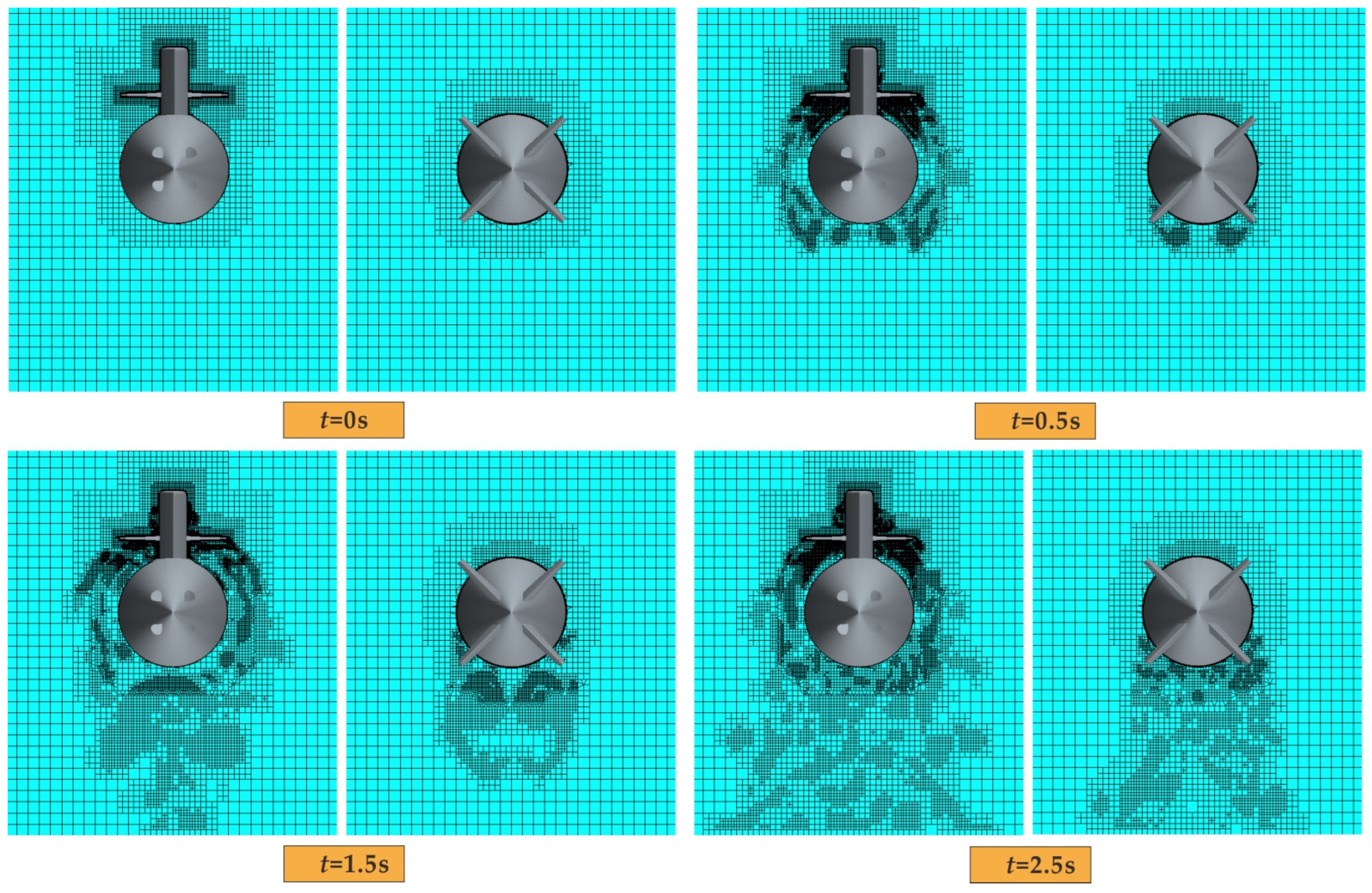
Figure 11 illustrates the schematic grid diagrams of the compartment (with sail rudder) and the cross-section of the submarine at different time instants during the flow around the vertical plane with a speed of w = 1.0 m/s. The demonstrated results indicate that the implementation of adaptive meshing allows for mesh refinement based on the vortex intensity, leading to a more reasonable mesh distribution and more accurate simulation results. Each case took approximately 50 h to compute on the server, utilizing three blades, each equipped with 128 GB of memory and 20 cores.

3.2.1. Comparison of the Mean Forces and Moments

Figure 12 shows a comparison between numerical calculations and experimental results for longitudinal force (Fx), vertical force (Fz), and pitching moment (My). The detailed statistical results are also presented in Table 4. It can be seen that the CFD calculations are generally in reasonably good agreement with the experimental results. At velocities below 1 m/s, the CFD calculations exhibit slightly larger discrepancies compared to the experimental results, while the discrepancies notably lessen at velocities above 1 m/s. The errors for Fx, Fz, and My, in order, range from 4.0% to 12.6%, 3.4% to 14.0%, and 3.0% to 13.8%, respectively. As a result, it can be concluded that the numerical calculation method using the SST-DDES model demonstrates effectiveness.

3.2.2. Comparison of the Time-History Forces and Moments

The focus of this study is primarily on the temporal variations of the lateral force (Fy), rolling moment (Mx), and yawing moment (Mz) experienced by the submarine hull during vertical plane flow. There are varying levels of noise interference due to factors such as trailer body vibration and force-induced fluctuations in the submarine support components. To reduce this, the data were processed using the Savitzky–Golay filter [30]. The Savitzky–Golay filter essentially employs a moving window and implements the least square method in the time domain to achieve optimal fitting. This filtering technique effectively eliminates noise while preserving the shape and width of the signal.
If the window size is set as 2n + 1, each measurement point can be represented by x = {−n, −n + 1, , 0, , n − 1, n}. When fitting the data within the window using an m − 1 degree polynomial is of interest, the polynomial can be expressed as follows:
y = a 0 + a 1 x + + a m 1 x m 1 ,
where a i , j [ 0 ,   m 1 ] represents the coefficients of the polynomial. With the aforementioned settings, a system of m linear equations consisting of 2n + 1 equations can be obtained, which is represented by the following:
Y ( 2 n + 1 ) × 1 = X ( 2 n + 1 ) × m A m 1 + E ( 2 n + 1 ) × 1
A solution to the aforementioned equations requires 2n + 1 > m. The coefficient vector can be obtained using the least square method:
A = ( X T X ) 1 X T Y
After obtaining the coefficient vector (A), the smoothed value is appropriately evaluated using this vector Y ^ = X A .
In this data processing, a larger window size can smooth longer signal cycles but may result in a slower filter response. A higher polynomial order can better fit the curve of the signal, but it may also introduce excessive noise or excessively smooth the signal. Therefore, to balance the signal smoothness and preservation of signal features, the window size was set equal to 21, and the polynomial order was considered to be 3. As an example, the experimental data for the lateral force (Fy) at a velocity of w = 1 m/s has been presented in Figure 13.
In comparing the time-domain data of Fy, Mx, and Mz of the numerical calculations and those of the experimental results, the vertical flow results were selected for three speeds in the experimental speed range (0.5, 1, and 1.6 m/s). Such comparison studies in the time-domain are provided in Figure 14, Figure 15 and Figure 16.
Due to the randomness of vortices, obtaining consistent time-domain data between experimental results and CFD calculations is somewhat difficult. Therefore, a comparison study was performed from the point of view of the force curve and amplitude. By looking at Figure 14, Figure 15 and Figure 16, regarding comparing the results at w = 0.5 m/s, the changing trends of the experimental results of Fy and Mz basically coincide with the simulation time-domain curves, but the amplitude errors are relatively large due to the fluctuation variations. Since Mx has a relatively small value, the experimental data fluctuate quite a lot. With increasing speed, the variable trends of Fy, Mx, and Mz experimental results are substantially consistent with the simulation time-domain curves, but there are still certain amplitude deviations. Table 5 provides the amplitudes of different directions of the considered major forces at different speeds. From the results of Table 5, it can be seen that, with increasing speed, the error lessens to some extent. The reasons for these errors can be analyzed from two aspects. On the one hand, when the speed is low, the force characteristics are not obvious, and the sensor is hardly capable of accurately measuring. On the other hand, the support structure of the experimental boat also affects the experimental data.
To further compare the experimental and simulation data, a Fourier transform was performed on the data to obtain their original frequencies. The statistical results of the main frequencies are presented in Table 6. It can be seen that, with increasing speed, the error of the main frequency gradually decreases. In the case of w = 1.6 m/s, the main frequency errors of Fy, Mx, and Mz are 0.6%, 0.9%, and 0.9%, respectively. By combining the comparison of Fy, Mx, and Mz time-domain data, it can be concluded that the numerical calculation method is reasonable.
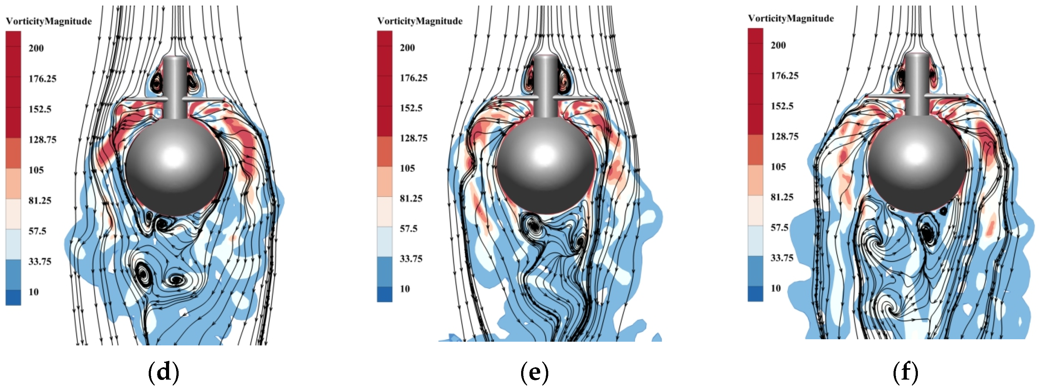
Figure 17 illustrates the vorticity distribution at six different time instants within one cycle at w = 1.6 m/s, showing the asymmetry of vorticity on both sides of the hull (with a sail and sail rudder). The vorticity is asymmetric on both sides at various instants, leading to the asymmetry of the generated Fy, Mx, and Mz fields of the hull.

4. Analysis

The focus of this paper is on the effect of flow motion around the vertical plane of a submarine at high angles of attack on the lateral force, rolling moment, and yawing moment. To determine the magnitudes of these forces and moments, let us define the following three parameters:
(1) The absolute value ratio between the magnitude of lateral force Fy and the mean value of vertical force Fz, the factor τ, is defined as follows:
τ = A m p ( F y ) / F z × 100 %
(2) The absolute value ratio between the magnitude of rolling moment Mx and the absolute value of the submarine’s moment per degree of roll Mθ, the factor χ, is defined as follows:
χ = A m p ( M x ) / M θ ,
where M θ = B × B G × sin ( π / 180 ) , B G = Z G Z B , and ZG and ZB represent the vertical coordinates of the center of gravity and the center of buoyancy, respectively.
(3) The absolute value ratio between the magnitude of yawing moment Mz and the mean value of pitching moment My, the factor σ, is defined as follows:
σ = A m p ( M z ) / M y × 100 %

4.1. Analysis of Forces Induced by Flow around the Vertical Plane

The acting forces are the lateral force (Fy), rolling moment (Mx), and yawing moment (Mz), as the vertical flow velocity (w) varies from 0 to 1.6 m/s. Figure 18a–c present the force results in the presence of various vertical flow velocities, while Figure 18d–f illustrate the values of τ, χ, and σ at different velocities.
From Figure 18a,d, it can be seen that, as the value of w increases, the average value of Fz and the value of Fy gradually increase, while the value of τ continuously reaches about 20%, significantly exceeding 10%. This fact indicates that the lateral force (Fy) exhibits considerable amplitude in motion and should not be neglected.
From Figure 18b,e, it can be seen that the value of χ exceeds 2 as w exceeds 0.6 m/s. As w increases, the value of χ also increases gradually. This issue demonstrates that the rolling moment (Mx) should not be neglected when w exceeds 0.6 m/s.
Figure 18c,f show that, as the value of w increases, the average value of My and the value of Mz increase gradually. In addition, when combined with the values of the rolling moment (Mx) in Figure 18b, it can be seen that the amplitude trend of Mz matches that of Mx. By observing the plotted results of σ, it can be concluded that the minimum and maximum values of this factor are obtained as 71.77% and 161.97%, respectively. This reveals that, with the gradual increase in the speed w, the amplitude of the yawing moment (Mz) will eventually exceed the average value of the pitching moment (My). Therefore, the yawing moment (Mz) cannot be neglected. It is also worth mentioning that My possesses a negative value and, in the figure, only numerical values are compared for convenience without considering the direction.
From the analysis, it can be concluded that, although the submarines are symmetrical about the vertical axis, the generation and detachment of vortices possess a special effect on the lateral force (Fy) and the yawing moment (Mz), which is applied to the horizontal plane of the submarine. In addition, when the vertical velocity (w) exceeds 0.6 m/s, it also exhibits a noticeable influence on the rolling moment Mx, and these effects cannot be ignored at all. In addition, it can be inferred that the trend of the Mz amplitude during the vertical motion of the submarine is closely related to the Mx.

4.2. Impact of the Angle of Attack on the Vertical Plane

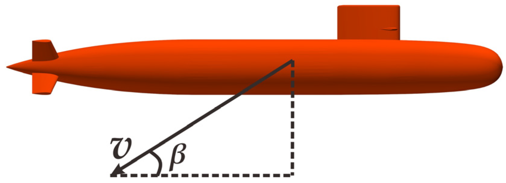
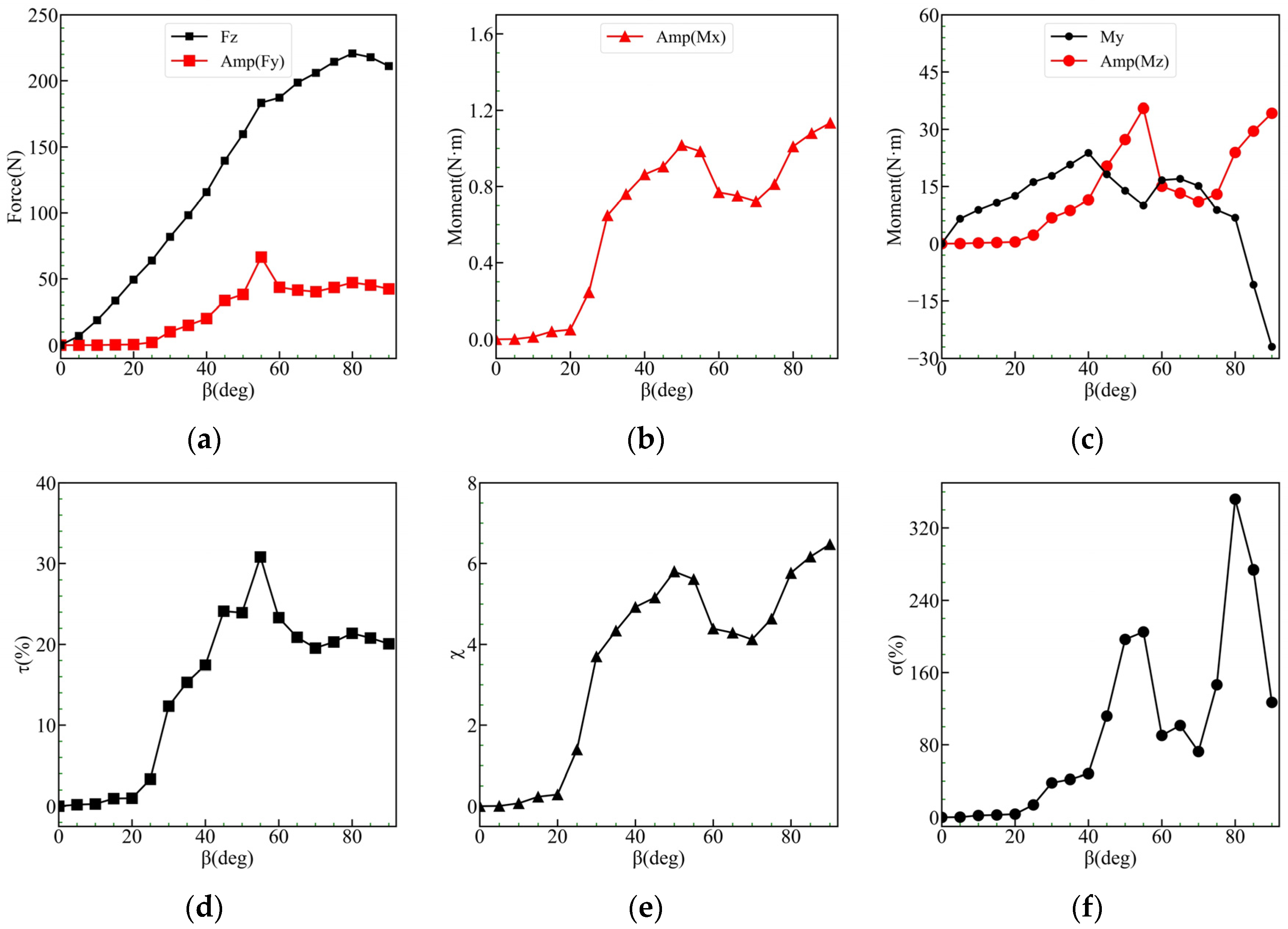
The NEU-based model was employed to assess the changes in the vertical angle of attack β in the range of 0–90°, with an interval of 5°. The effects of the vertical angle of attack on the lateral force, rolling moment, and yawing moment of the submarine were discussed. In order to simplify calculations and avoid an inconvenience caused by coordinate transformation, the submarine was kept fixed, and only the incident flow direction was changed. Figure 19 presents a schematic representation of the angle of attack (β) for ease of calculations.
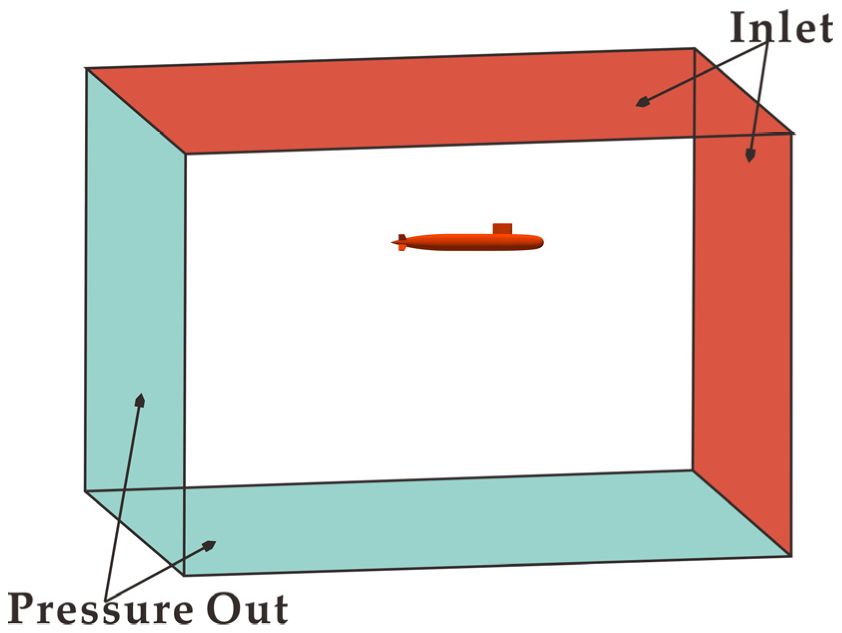
In the performed calculations, the incident flow velocity was maintained at V = 1 m/s. According to the changes in the incident flow direction, the boundary conditions of the computational domain were changed, as presented in Figure 20. The upstream and upper boundaries of the submarine were set as inflow velocity inlets, whereas the downstream and lower boundaries were defined as outflow pressure outlets. The lateral surfaces of the submarine were considered solid walls. The sizes of the computational domain and grid settings were the same as those given in the previous section.
The force conditions and the corresponding values of τ, χ, and σ at various angles of attack (β) are illustrated in Figure 21. The plotted results in Figure 21a,d reveal that, with the increase of β, the average magnitudes of Fz and Fy gradually rise. After β exceeds 55°, the rate of increase in the mean value of Fz slows down, while the magnitude of Fy remains relatively small and increases slowly before β reaches 25°. After reaching its peak at β = 55°, the magnitude of Fy starts to decrease gradually. As a result, the corresponding value of τ accelerates its increase when β exceeds 25°, and τ starts to exceed 10%. At an angle of attack β = 55°, τ reaches its maximum value of 36.26%. Subsequently, as β exceeds 55°, τ starts to decrease and then gradually stabilizes.
From Figure 21b,e, it can be seen that, when β is greater than 25°, the χ values are all greater than 2. When β is equal to 50°, χ reaches its first peak value of 5.81. Subsequently, χ starts to decrease and reaches its valley value at β = 70°, where χ is equal to 4.12. At β = 80°, χ reaches its second peak value of 6.71. After β exceeds 80°, χ undergoes slow changes.
Figure 21c,f show that, when β is less than 55°, the magnitude of Mz continues to increase. It gradually decreases between 55 and 75°, but it starts to increase again after 75°. As for the pitching moment My, there is a zero-crossing point between 80° and 85°, which leads to a significant increase in the value of σ. However, in general, the plot of σ exhibits a slight increase when β is less than 25°, but after crossing 25°, it gradually exceeds 40%. When considering the roll moment values from Figure 21b, it can still be seen that the overall trend of Mz magnitude is consistent with that of the Mx magnitude.
According to the above, it can be concluded that, under the flow speed v = 1 m/s, when the angle of the vertical plane of attack β exceeds 25°, the effects of Fy, Mx, and Mz cannot be ignored. The influence of the yawing moment (Mz) is particularly prominent, with its magnitude close to or exceeding the mean value of the pitching moment (My). Furthermore, it can still be observed that the overall trend of the Mz magnitude is generally consistent with the Mx magnitude.
Figure 22 demonstrates the distribution of vorticity at different sections of the NEU model for moments with attack angles (β) equal to 20°, 30°, 60°, and 80°. In the case of β = 20°, the vorticity distribution on both sides of the hull is relatively symmetrical. In addition, the horseshoe vortex movement process can be seen near the enclosure. As β increases to 30° and 60°, the asymmetry in the vorticity distribution between the left and right sides of the hull becomes more pronounced. Finally, at β = 80°, the vorticity distribution in different sections of the hull appears to be noticeably more irregular.

4.3. Impact of the Heel Angle

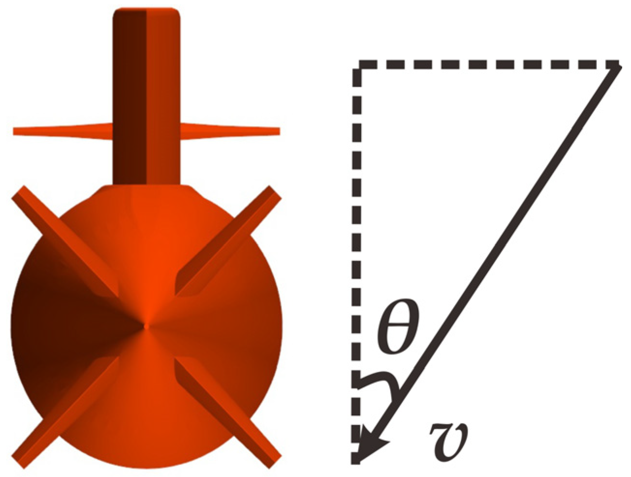
The effect of the heel angle change on the lateral force (Fy), rolling moment (Mx), and yawing moment (Mz) of the NEU-based model was evaluated in the presence of the vertical flow velocity of V = 1 m/s. The heel angle (θ) was varied from 0 to 80° in increments of 5°. As in the previous section, the hull was kept fixed, and the direction of the incoming flow was changed. Figure 23 illustrates the schematic diagram of the heel angle (θ).
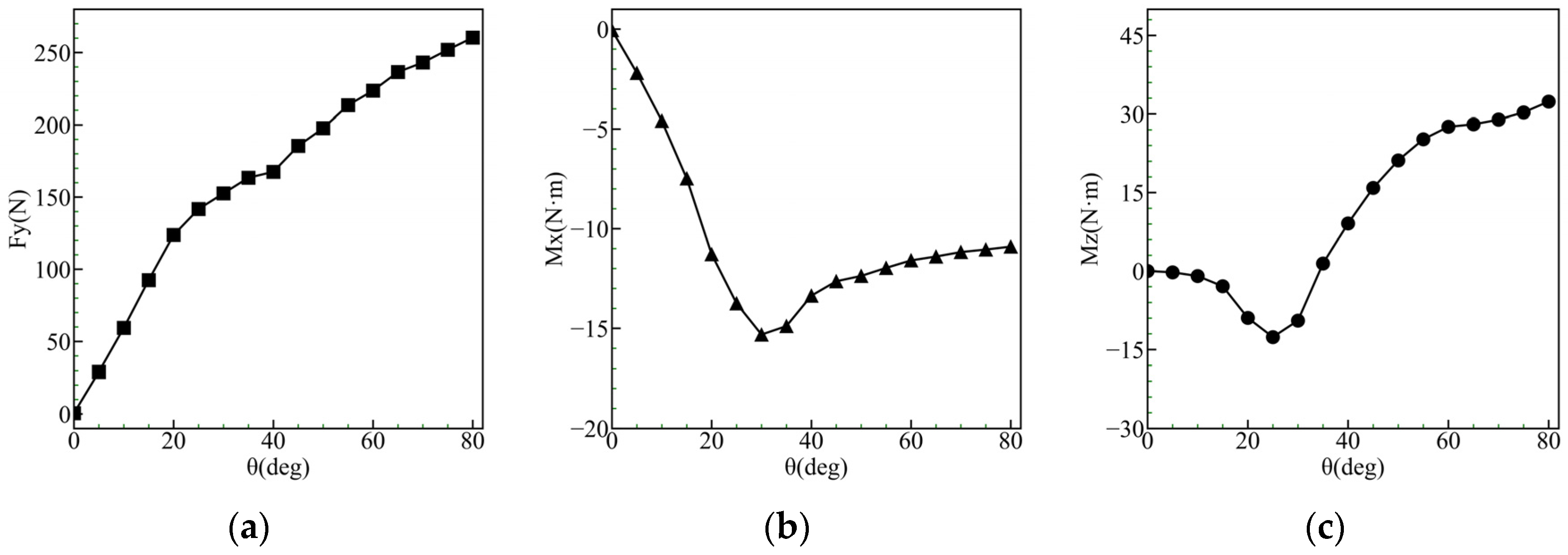
The presence of the heel angle (θ) is equivalent to a hull experiencing lateral flow, resulting in non-zero mean values for Fy, Mx, and Mz. Figure 24 presents the average values of Fy, Mx, and Mz at different heel angles (θ). Concerning the force Fy, it increases steadily with increasing θ, but the rate of increase becomes noticeably slower between 20° and 40°. Regarding the rolling moment Mx, it increases rapidly with increasing θ and peaks at around 30° before gradually decreasing to a steady state. In contrast, when θ is less than 25°, Mz increases continuously, but when θ exceeds 25°, it quickly reverses its direction and slowly rises after θ reaches 60°. Therefore, the presence of the heel angle intensifies the changes in the lateral force, rolling moment, and yawing moment.
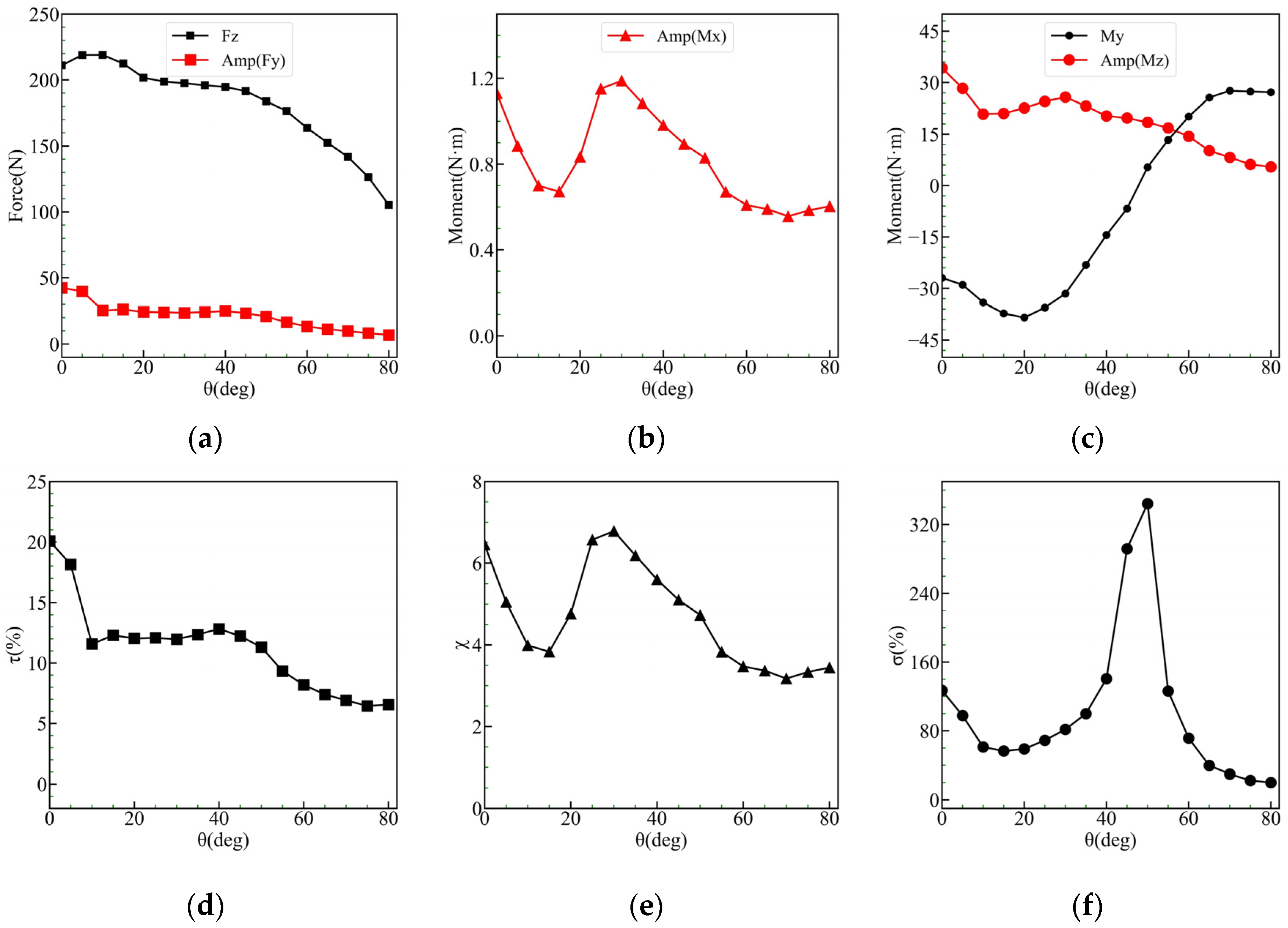
To further compare the magnitude of the lateral disturbance caused by the vertical velocity, Figure 25 shows the force distribution by subtracting the average values of Fy, Mx, and Mz as well as the values of τ, χ, and σ at different heel angles θ. By examining Figure 25a,d, it can be seen that both the average value of Fz and the amplitude of Fy gradually decrease with increasing θ. The value of τ decreases rapidly and stabilizes after a heel angle of 10° and continues to decrease when θ exceeds 45°. As θ exceeds 55°, the value of τ becomes less than 10%.
According to Figure 25b,e, it can be seen that the Mx amplitude shows a valley shape at about 15°, followed by a peak at about θ = 30°, then gradually lessens before stabilizing. By considering Figure 25c,f, it is similarly evident that, as θ increases, the overall trend of the Mz amplitude is similar to that of Mx, but the “peaks and valleys” of Mz are not as distinct as those of Mx. As a result of the change in the direction of the pitching moment My in terms of θ, a significant peak in the value of σ occurs at θ = 50°. Then, when θ exceeds 65°, the value of σ drops below 40%.
In summary, by performing calculations for the range of heel angles (θ) from 0 to 80° under a free-stream velocity of v = 1 m/s, it can be concluded that the increase in θ intensifies the magnitude of the lateral force Fy. Furthermore, in practical scenarios, it is very unlikely that the heel angle will exceed 50°. Therefore, the effects of the vertical velocity on the forces Fy, Mx, and Mz cannot be ignored.
Figure 26 presents the vorticity and streamlines at a particular instant for different heel angles near the hull. It can be observed that, as the heel angle increases, the asymmetry in the vortex between the left and right sides of the hull becomes more obvious.

5. Conclusions

The numerical simulations of the flow around a submarine vertical plane at high angles of attack were methodically carried out using the SST-DDES model in conjunction with AMR technology. A new omega vorticity identification approach was employed as the adaptive criterion. The numerical method was validated through flow calculations around a cylinder and water tank experiment of flow around the vertical plane of the submarine. The effects of different attack angles and heel angles on the submarine lateral force, rolling moment, and yawing moment were methodically analyzed. The following results can be obtained:
(1) It is possible to simulate the unsteady flow around a submarine vertical plane via the SST-DDES model in conjunction with AMR technology. A comparison between the calculated average values of longitudinal force Fx, vertical force Fz, and pitching moment My and the experimental results shows an error range of 3.0% to 14.0%. In addition, comparing the time-history data of the lateral force Fy, rolling moment Mx, and yawing moment Mz with the experimental results reveals a significant consistency in the trends of Fy, Mx, and Mz. The minimum errors in Fy, Mx, and Mz magnitudes are obtained as 13.9%, 7.4%, and 11.9%, while the minimum errors in their dominant frequencies are obtained as 0.6%, 0.9%, and 0.9%, respectively.
(2) In calculating the flow around the vertical plane of the submarine, it was found that the vertical velocity of the hull has a special effect on the horizontal forces. Specifically, the magnitude of Fy accounts for approximately 20% of the average value of Fz, and the ratio of the magnitude of Mz to the average value of My ranges from 71.77% to 161.97%. Therefore, when studying the motion of the vertical plane of the submarine, the effects of lateral force and yawing moment cannot be ignored. Similarly, the influence of the rolling moment cannot be neglected when the vertical velocity of the hull w exceeds 0.6 m/s; the effect of the rolling moment cannot be ignored.
(3) When analyzing the influence of the angle of attack of the submarine vertical plane, it can be seen that, when the angle of attack exceeds 25°, the roles of Fy, Mx, and Mz cannot be ignored. In particular, the influence of the yawing moment Mz is highlighted when its value approaches or exceeds the average value of the pitching moment My.
(4) The presence of the roll angle (θ) during the motion of the vertical plane of the submarine intensifies the forces on Fy, Mx, and Mz induced by the vertical velocity. The forces on Fy, Mx, and Mz are caused by the vertical velocity. The effect of forces on Fy, Mx, and Mz due to the vertical velocity cannot be neglected.
(5) During the motion of the vertical plane of the submarine, regardless of the angle of attack and the roll angle, it was found that the trend of changes in the magnitude of Mz closely follows that of Mx.
(6) In the case of the angle of attack above the vertical plane of the submarine, the lateral force, the rolling moment, and the yawing moment influence and affect each other. This is a complex nonlinear problem, and in future research, the effects of forces on these three parameters should be methodically examined during the dynamic process. We will focus on quantitatively describing these hydrodynamic forces using mathematical models, aiming to establish a mathematical model applicable to the up-surfacing motion of submarines at large angles of attack.

Author Contributions

Conceptualization, G.X. and Y.O.; methodology, G.X. and J.C.; validation, H.W., W.W. and Y.O.; writing—original draft preparation, G.X.; writing—review and editing, Y.O. and H.W.; supervision, W.W.; project administration, Y.O.; funding acquisition, Y.O. All authors have read and agreed to the published version of the manuscript.

Funding

This work was supported by the Pre-Research on Equipment (Shared Technology) of China under Grant 41407020602.

Institutional Review Board Statement

Not applicable.

Informed Consent Statement

Not applicable.

Data Availability Statement

The data presented in this study are available on request from the corresponding author. The data are not publicly available due to privacy restrictions.

Conflicts of Interest

The authors declare no conflicts of interest.

References

  1. Schreur, B.G.J.W. The Motion of Buoyant Bodies. Ph.D. Thesis, Trinity College, Cambridge, UK, 1990. [Google Scholar]
  2. Itard, X. Recovery procedure in case of flooding. In Proceedings of the Warship-International Symposium Then Conference, Brisbane, Australia, 22–25 August 1999. [Google Scholar]
  3. Watt, G.D.; Bohlmann, H.J. Submarine rising stability: Quasi-steady theory and unsteady effects. In Proceedings of the 25th Symposium on Naval Hydrodynamics, St. John, NL, Canada, 8–13 August 2004. [Google Scholar]
  4. Bettle, M.C.; Gerber, A.G.; Watt, G.D. Unsteady analysis of the six DOF motion of a buoyantly rising submarine. Comput. Fluids 2009, 38, 1833–1849. [Google Scholar] [CrossRef]
  5. Chen, Q.; Li, H.; Pang, Y.; Zhang, S.; Chang, W. Investigation of the excess roll problem of an emergent buoyantly rising submarine. J. Fluids Struct. 2019, 91, 102720. [Google Scholar] [CrossRef]
  6. Watt, G.D. Modelling and Simulating Unsteady Six Degrees-of-Freedom Submarine Rising Maneuvers; Defence R&D Canada-Atlantic: Dartmouth, NS, Canada, 2007. [Google Scholar]
  7. Liang, X.; Ma, N.; Liu, H.; Gu, X. Experimental study on the maneuvering derivatives of a half-scale SUBOFF model in the vertical plane. Ocean Eng. 2021, 233, 109052. [Google Scholar] [CrossRef]
  8. Sohail, M.; Chao, Y.; Ullah, R.; Yamin, M. Computational challenges in high angle of attack flow. World Acad. Sci. Eng. Technol. 2011, 80, 1148–1155. [Google Scholar]
  9. Ma, B.; Huang, Y.; Liu, T. Low-frequency unsteadiness of vortex wakes over slender bodies at high angle of attack. Chin. J. Aeronaut. 2014, 27, 772–780. [Google Scholar] [CrossRef]
  10. Le Clainche, S.; Li, J.I.; Theofilis, V.; Soria, J. Flow around a hemisphere-cylinder at high angle of attack and low Reynolds number. Part I: Experimental and numerical investigation. Aerosp. Sci. Technol. 2015, 44, 77–87. [Google Scholar] [CrossRef]
  11. Le Clainche, S.; Rodríguez, D.; Theofilis, V.; Soria, J. Flow around a hemisphere-cylinder at high angle of attack and low Reynolds number. Part II: POD and DMD applied to reduced domains. Aerosp. Sci. Technol. 2015, 44, 88–100. [Google Scholar] [CrossRef]
  12. de Moraes, P.G.; de Oliveira, M.A.; de Andrade, C.L.; Bimbato, A.M.; Alcântara Pereira, L.A. Effects of surface roughness and wall confinement on bluff body aerodynamics at large-gap regime. J. Braz. Soc. Mech. Sci. Eng. 2021, 43, 397. [Google Scholar] [CrossRef]
  13. Han, X.; Tang, Y.; Meng, Z.; Fu, F.; Qiu, A.; Gu, J.; Wu, J. Surface roughness effect on cylinder vortex-induced vibration at moderate Re regimes. Ocean Eng. 2021, 224, 108690. [Google Scholar] [CrossRef]
  14. Strelets, M. Detached Eddy Simulation of Massively Separated Flows. In Proceedings of the 39th Aerospace Sciences Meeting and Exhibit, Reno, NV, USA, 8–11 January 2001. [Google Scholar]
  15. Spalart, P.; Jou, W.H.; Strelets, M.; Allmaras, S. Comments on the Feasibility of LES for Wings, and on a Hybrid RANS/LES Approach. In Proceedings of the First AFOSR International Conference on DNS/LES, Ruston, LA, USA, 4–8 August 1997. [Google Scholar]
  16. Weiwen, Z.; Decheng, W. Detached Eddy Simulation of Flow Past Tandem Cylinders. Appl. Math. Mech. 2016, 37, 1272. [Google Scholar]
  17. Nguyen, V.T.; Nguyun, H.H. Detached eddy simulations of flow induced vibrations of circular cylinders at high Reynolds numbers. J. Fluids Struct. 2016, 63, 103–119. [Google Scholar] [CrossRef]
  18. Yao, J.; Jinsheng, C.; Fei, L. Comparative Numerical Studies of Flow Past Cylinder at Reynolds Number 3900. Appl. Math. Mech. 2016, 37, 1282. [Google Scholar]
  19. Liu, Z.; Yang, Y.; Zhou, W.; Gong, A. Study of Unsteady Separation Flow Around Airfoil at High Angle of Attack Using Hybrid RANS-LES Method. Acta Aeronaut. Astronaut. Sin. 2014, 35, 372–380. [Google Scholar]
  20. Oliger, B.J. Adaptive mesh refinement for hyperbolic partial differential equations. J. Comput. Phys. 1984, 52, 484–512. [Google Scholar]
  21. Bao, G.; Chen, Z.; Wu, H. Adaptive finite-element method for diffraction gratings. J. Opt. Soc. Am. A 2005, 22, 1106–1114. [Google Scholar] [CrossRef] [PubMed]
  22. Golay, F.; Ersoy, M.; Yushchenko, L.; Sous, D. Block-based adaptive mesh refinement scheme using numerical density ofentropy production for three-dimensional two-fluid flows. Int. J. Comput. Fluid Dyn. 2015, 29, 67–81. [Google Scholar] [CrossRef]
  23. Gou, J.; Su, X.; Yuan, X. Adaptive mesh refinement method-based large eddy simulation for the flow over circular cylinder at ReD = 3900. Int. J. Comput. Fluid Dyn. 2018, 32, 1–8. [Google Scholar] [CrossRef]
  24. Mozaffari, S.; Guilmineau, E.; Visonneau, M.; Wackers, J. Average-based mesh adaptation for hybrid RANS/LES simulation of complex flows. Comput. Fluids 2022, 232, 105202. [Google Scholar] [CrossRef]
  25. Liu, C.Q.; Wang, Y.Q.; Yang, Y.; Duan, Z.W. New omega vortex identification method. Sci. China 2016, 59, 684711. [Google Scholar] [CrossRef]
  26. Menter, F.R. Two-Equation Eddy-Viscosity Transport Turbulence Model for Engineering Applications. AIAA J. 1994, 32, 1598–1605. [Google Scholar] [CrossRef]
  27. Spalart, P.R.; Deck, S.; Shur, M.L.; Squires, K.D.; Strelets, M.K.; Travin, A. A New Version of Detached-eddy Simulation, Resistant to Ambiguous Grid Densities. Theor. Comput. Fluid Dyn. 2006, 20, 181–195. [Google Scholar] [CrossRef]
  28. Dong, X.; Wang, Y.; Chen, X.; Dong, Y.; Zhang, Y.; Liu, C. Determination of epsilon for Omega vortex identification method. J. Hydrodyn. 2018, 30, 541–548. [Google Scholar] [CrossRef]
  29. Parnaudeau, P.; Carlier, J.; Heitz, D.; Lamballais, E. Experimental and numerical studies of the flow over a circular cylinder at Reynolds number 3900. Phys. Fluids 2008, 20, 085101. [Google Scholar] [CrossRef]
  30. Savitzky, A.; Golay, M.J.E. Smoothing and Differentiation of Data by Simplified Least Squares Procedures. Anal. Chem. 1964, 36, 1627–1639. [Google Scholar] [CrossRef]
Figure 1. The established NEU model and coordinate system.
Applsci 14 00395 g001
Figure 2. Adaptive mesh refinement levels. (a) initial mesh; (b) level 1; (c) level 2; (d) level 3.
Applsci 14 00395 g002
Figure 3. The computational domain and the corresponding mesh. (a) Computational domain; (b) Region mesh.
Applsci 14 00395 g003
Figure 4. Schematic representation of: (a) Experiment, (b) Hull experimental installation.
Applsci 14 00395 g004
Figure 5. Sensors and their installations. (a) Sensors; (b) Sensors installation.
Applsci 14 00395 g005
Figure 6. Computational domain and the considered mesh for the flow around a cylinder. (a) domain; (b) domain mesh.
Applsci 14 00395 g006
Figure 7. Typical parameter plotted results. (a) Lift and spectrum; (b) Separation angle.
Applsci 14 00395 g007
Figure 8. Average pressure coefficient on the cylinder surface.
Applsci 14 00395 g008
Figure 9. Average velocity profiles at three sectional positions. (a) Average velocity profiles of the x-direction; (b) average velocity profiles of the y-direction.
Applsci 14 00395 g009
Figure 10. Adaptive mesh for flow around a cylinder at various time instants.
Applsci 14 00395 g010
Figure 11. Adaptive mesh for the flow around a vertical plane at various time instants.
Applsci 14 00395 g011
Figure 12. Comparison of the CFD mean forces with the experimental results. (a) Fx; (b) Fz; (c) My.
Applsci 14 00395 g012
Figure 13. Comparison between the raw and filtered data of the lateral force Fy at w = 1.0 m/s.
Applsci 14 00395 g013
Figure 14. Comparison of forces in three directions at w = 0.5 m/s. (a) Fy; (b) Mx; (c) Mz.
Applsci 14 00395 g014
Figure 15. Comparison of forces in three directions at w = 1.0 m/s. (a) Fy; (b) Mx; (c) Mz.
Applsci 14 00395 g015
Figure 16. Comparison of forces in three directions at w = 1.6 m/s. (a) Fy; (b) Mx; (c) Mz.
Applsci 14 00395 g016
Figure 17. Vorticity distribution at various time instants near the hull (with sail and sail rudder) for the case of w = 1.6 m/s: (a) t = 10.0 s, (b) t = 10.5 s, (c) t = 11.0 s, (d) t = 11.5 s, (e) t = 12.0 s, (f) t = 12.5 s.
Applsci 14 00395 g017aApplsci 14 00395 g017b
Figure 18. Forces induced by the flow around a vertical plane at various flow velocities. (a) Fz and amplitude of Fy, (b) amplitude of Mx, (c) My and amplitude of Mz, (d) the values of τ, (e) the values χ, (f) the values of σ.
Applsci 14 00395 g018
Figure 19. Plots of the angle of attack (β).
Applsci 14 00395 g019
Figure 20. Boundary conditions of the computational domain.
Applsci 14 00395 g020
Figure 21. Force statistics for various angles of attack (β). (a) Fz and amplitude of Fy, (b) amplitude of Mx, (c) My and amplitude of Mz, (d) the values of τ, (e) the values χ, (f) the values of σ.
Applsci 14 00395 g021
Figure 22. Hull vorticity maps at various angles of attack (β). (a) β = 20°, (b) β = 30°, (c) β = 60°, (d) β = 80°.
Applsci 14 00395 g022aApplsci 14 00395 g022b
Figure 23. Heel angle (θ).
Applsci 14 00395 g023
Figure 24. The mean values of Fy, Mx, and Mz at various heel angles (θ). (a) the mean values of Fy; (b) the mean values of Mx; (c) the mean values of Mz.
Applsci 14 00395 g024
Figure 25. Force statistics for various angles of heel (θ). (a) Fz and amplitude of Fy, (b) amplitude of Mx, (c) My and amplitude of Mz, (d) the values of τ, (e) the values χ, (f) the values of σ.
Applsci 14 00395 g025
Figure 26. Hull vorticity contour maps at various heel angles (θ). (a) θ = 5°, (b) θ = 20°, (c) θ = 50°, (d) θ = 80°.
Applsci 14 00395 g026
Table 1. The main parameters of the NEU-based model.
ParameterUnitValue
Total length Lm3.0
Diameter DLm0.3
Displacement Δkg170.5
Height of CB above CG BGm0.006
Roll moment per degree MθN·m0.175
Table 2. Performance parameters of the towing tank.
ParameterUnitValue
Towing tank dimensionsm510 × 6.5 × 5
Effective working lengthm450
Depthm2.5
Towing speedm/s0.5~12
Towing speed error-<1.5%
Table 3. Typical parameter results for the flow around a cylinder (Re = 3900).
StψUmin/U0
Experiment0.208 ± 0.00286.0° ± 2−0.340
SST-DDES0.21387.2−0.312
Table 4. Statistics of the CFD mean forces and the experimental results.
w
(m/s)
Fx (N)Fz (N)My (N·m)
EXP.CFDErrorEXP.CFDErrorEXP.CFDError
0.58.207.1712.6%63.0454.2514.0%8.147.2710.7%
0.820.8919.218.0%147.11136.407.3%19.3717.4310.0%
132.8530.955.8%231.58215.077.1%27.8026.953.0%
1.248.5945.706.0%321.33305.045.1%37.5035.684.9%
1.466.4362.945.3%430.21415.493.4%50.4947.595.7%
1.687.9584.044.4%569.68544.344.4%66.9363.465.2%
Table 5. Amplitude statistics of Fy, Mx, and Mz.
w
(m/s)
Amplitude of Fy (N)Amplitude of Mx (N·m)Amplitude of Mz (N·m)
EXP.CFDErrorEXP.CFDErrorEXP.CFDError
0.515.479.1440.9%0.620.3839.3%13.418.5036.7%
1.055.3444.7319.2%1.581.3216.6%52.9342.9618.8%
1.6112.24127.8913.9%3.513.777.4%116.73102.7911.9%
Table 6. Comparison of the fundamental frequencies of the time-history data for Fy, Mx, and Mz.
w
(m/s)
Fundamental
Frequency of Fy
Fundamental
Frequency of Mx
Fundamental
Frequency of Mz
EXP.CFDErrorEXP.CFDErrorEXP.CFDError
0.50.1330.10025.0%0.1430.10030.2%0.1270.10021.5%
1.00.2190.2008.7%0.2310.20013.4%0.2120.2005.6%
1.60.3510.3490.6%0.3470.3500.9%0.3530.3500.9%
Disclaimer/Publisher’s Note: The statements, opinions and data contained in all publications are solely those of the individual author(s) and contributor(s) and not of MDPI and/or the editor(s). MDPI and/or the editor(s) disclaim responsibility for any injury to people or property resulting from any ideas, methods, instructions or products referred to in the content.