Abstract
Flexible transparent electrodes are integral to the advancement of flexible optoelectronic devices such as flexible displays and solar cells. However, indium tin oxide (ITO), a traditional material used in transparent electrodes, exhibits a significant increase in resistance under mechanical stress, which limits the long-term stability of flexible devices. Here, we prepare various types of silver nanowire (AgNW)-based transparent electrodes and investigate their stability in terms of electrical resistance and optical transmittance under compressive and tensile stresses. Under compressive stress, ITO on a polyethylene terephthalate (PET) substrate exhibits a significantly high electrical resistance of >3000 Ω after 1000 stress cycles, while the AgNW-coated electrode on a PET film exhibits a relatively smaller resistance of <1200 Ω. The AgNW-embedded electrode in a UV-curable polymer matrix (NOA63 or NOA71) exhibits an even lower electrical resistance of <450 Ω because AgNWs can easily maintain their network. A similar trend is observed under tensile stress. The AgNW-embedded electrode shows the highest resistance stability, whereas the ITO on the PET substrate shows the poorest stability. The optical transmittance is comparable regardless of the type of stress or electrode used. This superior stability of the AgNW-based electrodes, realized by integrating it with a polymer matrix, is promising for the development of durable and high-performance flexible optoelectronic devices.
1. Introduction
Electronic components have evolved from heavy and rigid into lightweight and flexible structures, thereby allowing us the flexibility to use various devices anytime, anywhere [1,2,3]. Specifically, traditional transistors are heavy and inflexible, but recently reported transistors have been manufactured in lightweight and flexible forms capable of bending and stretching [4,5,6]. Similarly, solar cells, which were traditionally manufactured using rigid inorganic materials, now have lightweight and portable device architectures [7,8,9,10]. One of the strategies that can provide such flexibility and lightness to various optoelectronic components is the adoption of flexible transparent electrodes [11,12]. Flexible transparent electrodes have been developed based on organic and nanomaterials, which has made heavy and unbendable substrates redundant [13,14,15].
Early flexible transparent electrodes were fabricated by depositing indium tin oxide (ITO) onto polyethylene terephthalate (PET) films [16,17,18]. The ITO deposition techniques are highly mature and therefore offer the advantage of ease of production [19,20]. However, ITO, a ceramic material based on inorganic elements, generates cracks when subjected to external stress, resulting in an increase in the resistance of transparent electrodes and limiting the service life of flexible electronic components [21,22,23]. Various materials have been developed to overcome these challenges. Silver nanowires (AgNWs) are one of the promising materials for producing flexible electrodes with long-term stability [24,25,26]. People have reported various applications of AgNW-based electrodes, including solar cells, organic light-emitting displays, and sensors [27,28,29]. Flexible electrodes based on AgNWs are manufactured by simply coating AgNWs on a PET substrate or by coating AgNWs on a substrate with weak adhesion, pouring the polymer on top, curing it, and then peeling it off to create a AgNW-embedded form in the polymer [30,31]. They have been demonstrated to be applicable in various optoelectronic devices such as solar cells and organic light-emitting devices [32,33,34]. However, how various types of AgNW-based electrodes exhibit different behaviors and how their physical properties change depending on the type of external stress have not yet been investigated.
In this study, we investigated the changes in the electrical, morphological, and optical characteristics of AgNW-exposed and AgNW-embedded electrodes under compressive and tensile stress. For the fabrication of AgNW-exposed electrodes, PET was used as the substrate, and NOA63 and NOA71 were used for the AgNW-embedding process. The sheet resistance was measured to evaluate the electrical properties. The morphological properties were analyzed using scanning electron microscopy (SEM) and atomic force microscopy (AFM). Further, ultraviolet–visible (UV-Vis) spectroscopy measurements were conducted to evaluate the optical properties. Through a comprehensive analysis of these characteristics, we determined which electrode configuration performs optimally as a flexible transparent electrode under compressive and tensile stresses.
2. Materials and Methods
To observe the effect of external compressive and tensile stresses on the properties of flexible transparent electrodes, an ITO electrode on a PET film was purchased and AgNW-based flexible transparent electrodes were prepared. For the AgNW-based transparent electrodes, a AgNW-exposed electrode, where the AgNWs were exposed to air, and a AgNW-embedded electrode, where the silver nanowires were impregnated onto a polymer surface, were fabricated. The ITO electrode on the PET film was purchased from Sigma-Aldrich and used as received. The thicknesses of the ITO and PET film were 130 nm and 127 µm, respectively. The AgNW-exposed electrode was manufactured by spin-coating a 0.3 wt% AgNW solution in deionized water (C3nano Korea, Yongin, Republic of Korea) on a PET film and drying it on a hot plate. The diameter and length of the AgNWs were 25 nm and 25 µm, respectively. Spin-coating was performed at 1000 rpm for 60 s, followed by a drying process at 100 °C for 60 s. The AgNW-embedded electrode was fabricated by coating an anti-adhesive layer on a glass substrate, coating a silver nanowire on the anti-adhesive layer, coating an ultraviolet (UV)-curable polymer on the silver nanowire, curing it under UV illumination, and then peeling it off from the anti-adhesive layer. Poly(methyl methacrylate) (PMMA, Kayaku, Westborough, MA, USA) was used as the anti-adhesive material, which was spin-coated at 3000 rpm for 60 s and dried on a hot plate at 180 °C for 30 s to form an anti-adhesive layer. The AgNW solution was also coated and dried under the same conditions to form a AgNW layer as mentioned above. NOA63 (Norland Products Inc., Jameburg, NJ, USA) and NOA71 (Norland Products Inc.) were used as polymers for embedding the AgNWs. The viscosities of NOA63 and NOA71 were 2000 cps and 200 cps at 25 °C, respectively. The moduli of elasticity were 240,000 psi for NOA63 and 55,000 psi for NOA71, respectively. The tensile strengths were 5000 psi for NOA63 and 1300 psi for NOA71. NOA63 and NOA71 were spin-coated at 500 rpm for 60 s, followed by curing under 365 nm UV illumination for 90 min. This resulted in a 70 µm-thick NOA63 layer and a 25 µm-thick NOA71 layer, respectively. NOA63 and NOA71 have different viscosities; thus, the thicknesses of NOA63 and NOA71 were different under the same spin-coating conditions. They were then peeled off from the anti-adhesive layer to complete the fabrication of the AgNW-embedded electrode [32]. The AgNW thickness for the conduction path was the same in both AgNW-embedded electrodes because the spin-coating conditions for AgNWs were the same.
After preparing various flexible electrodes, their electrical, morphological, and optical properties were examined by applying compressive and tensile stresses. Assuming that the conductive material was located on the top surface, the electrodes were bent upward to induce compressive stress and downward to induce tensile stress. The bending radius was 4 mm under each stress condition. The sheet resistance was measured to examine the effect of external stress on the electrical characteristics. After five samples of each electrode type were tested, the average value and standard deviation were calculated excluding the maximum and minimum values. A four-point probe meter (EDTM, RC2175) was used to measure the sheet resistance, and the change in the resistance depending on the number of stress applications was recorded. Next, the morphological changes were examined to investigate the factors that result in changes in resistance. Morphological characteristics were analyzed via SEM (FE-SEM, JSM-6500F, JEOL, Peabody, MA, USA) and AFM (XE-100, Park Systems, Suwon, Republic of Korea), and crack generation and crack density were observed. In addition, the optical transmittance was analyzed using UV-Vis spectroscopy (UV-2600, Shimadzu, Kyoto, Japan) to investigate the effect of external stress on the optical characteristics. The wavelength range for the transmittance measurements was 300–800 nm.
3. Results and Discussion
To investigate the effect of compressive stress on the electrical properties of various types of AgNW-based electrodes, sheet resistances were measured depending on the number of compressive stresses applied to the electrodes. Figure 1 shows the sheet resistance depending on the number of compressive stresses applied to an ITO electrode on a PET film, a AgNW-exposed electrode, and a AgNW-embedded electrode. As shown in Figure 1a, the sheet resistance of the ITO electrode on the PET film increased linearly with the application of compressive stress. While the initial sheet resistance was 93 Ω/sq, the sheet resistance increased to 2214 Ω/sq after compressive stress was applied 500 times and to 3173 Ω/sq after compressive stress was applied 1000 times. This indicates that the ITO electrode on the PET film is no longer suitable for electronic device applications. In contrast, the AgNW-exposed electrode exhibited relatively stable electrical characteristics under compressive stress. Although the sheet resistance increased according to the number of compressive stresses, it was only approximately 572 Ω/sq when compressive stress was applied 500 times and 1178 Ω/sq when compressive stress was applied 1000 times (Figure 1b). The sheet resistance was approximately 1/3 of that of the ITO electrode on the PET film at an identical number of compressive stresses. The AgNW-embedded electrode exhibited better stability under compressive stress than the AgNW-exposed electrode. First, when NOA63 was used as a polymer for embedding AgNWs, the sheet resistance was approximately 325 Ω/sq when compressive stress was applied 500 times and approximately 441 Ω/sq when it was applied 1000 times (Figure 1c). These were approximately 1/10 of the sheet resistance of the ITO electrode on the PET film and 1/2 of that of the AgNW-exposed electrode, indicating the superiority of the AgNW-embedded electrode. Even when the polymer for the embedding process was changed to NOA71, there was no significant change in sheet resistance characteristics upon application of compressive stress. As shown in Figure 1d, the sheet resistance was approximately 334 Ω/sq when stress was applied 500 times, and approximately 343 Ω/sq when stress was applied 1000 times. Therefore, as long as the polymer used for the embedding process is sufficiently flexible, sufficient stability under compressive stress can be ensured for a AgNW-embedded electrode.
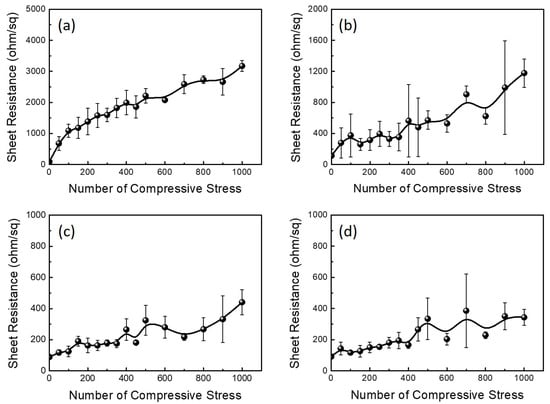
Figure 1.
Sheet resistance of (a) ITO electrode on a PET film, (b) AgNW-exposed electrode on a PET film, (c) AgNW-embedded electrode inside NOA63 and (d) AgNW-embedded electrode inside NOA71 depending on the number of compressive stresses. The bending radius was 4 mm.
To determine why the sheet resistance of the ITO electrode on the PET film increased rapidly and why the AgNW-based electrodes showed good electrical stability with the application of compressive stress, the surface of each electrode was observed using SEM and AFM after applying compressive stress 1000 times. Figure 2 shows SEM and AFM images before and after applying compressive stress to the ITO electrode. The SEM image shows the smooth surface of the ITO electrode before applying compressive stress (Figure 2a). In contrast, a large crack is observed in the SEM image of the ITO electrode after the application of compressive stress (Figure 2b). The SEM results indicate that the compressive stress generated cracks on the rigid ITO surface. The AFM image also shows the changes on the surface upon applying compressive stress. As shown in Figure 2c, the ITO electrode on the PET film exhibits a flat surface with an RMS roughness of 1.9 nm. However, after applying the compressive stress 1000 times, the ITO electrode appeared to float on the PET film and exhibited an RMS roughness of 170.0 nm. This indicates that cracks occurred on the ITO surface due to compressive stress, and the sheet resistance continued to increase with crack growth. Figure 3 shows SEM and AFM images of the AgNW-exposed electrode. First, large cracks, which were observed in the ITO electrode, were not found on the AgNW-exposed electrode; however, local bending or breaking of the AgNWs was observed in the SEM image. The AgNW-exposed electrode also showed a much smaller increase in the RMS roughness than that of the ITO/PET electrode in the AFM image. The RMS roughness values before and after applying the compressive stress were 9.8 and 12.9 nm, respectively. The SEM and AFM images indicate that although some of the AgNWs can be bent or broken owing to compressive stress, this is rare. Therefore, the surface morphology can generally be maintained, resulting in a minor increase in the sheet resistance. The AgNW-embedded electrode showed a more stable surface morphology under compressive stress than the ITO/PET and AgNW-exposed electrodes, regardless of the type of polymer used for the embedding process. Figure 4 shows SEM and AFM images of the AgNW-embedded electrodes prepared with NOA63 and NOA71. As shown in the SEM image, few cracks or broken AgNWs were detected on the surface, and the RMS roughness maintained a low value regardless of the compressive stress. Specifically, the AgNW electrode embedded with NOA63 showed an RMS roughness of 3.7 and 3.4 nm, respectively, before and after applying compressive stress. The AgNW electrode embedded with NOA71 showed an RMS roughness of 1.6 and 2.7 nm, respectively, before and after compressive stress was applied, thereby maintaining a low level. In conclusion, the AgNW-embedded electrode exhibited low resistance even after applying compressive stress 1000 times because the effect of compressive stress on the surface morphology is too small to generate cracks. This is attributed to the ability of the polymer to release the applied compressive stress and maintain the AgNW network.
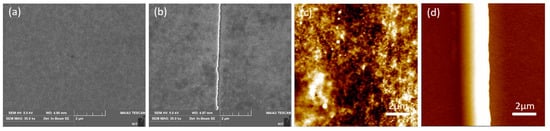
Figure 2.
(a,b) SEM and (c,d) AFM images of ITO electrode on a PET film (a,c) before and (b,d) after applying compressive stress. The RMS roughness values before and after applying compressive stress were 1.9 nm and 170.0 nm, respectively.
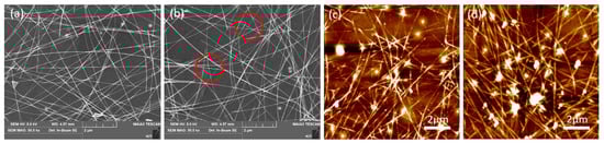
Figure 3.
(a,b) SEM and (c,d) AFM images of AgNW-exposed electrode on a PET film (a,c) before and (b,d) after applying compressive stress. The RMS roughness values before and after applying compressive stress were 9.8 nm and 12.9 nm, respectively.
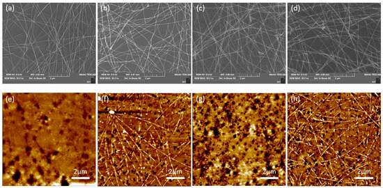
Figure 4.
(a–d) SEM and (e,h) AFM images of AgNW-embedded electrode in (a,b,e,f) NOA63 and (c,d,g,h) NOA71 (a,c,e,g) before and (b,d,f,h) after applying compressive stress. The RMS roughness values of the AgNW-embedded electrode in NOA63 were 3.7 nm and 3.4 nm before and after applying compressive stress, respectively. The RMS roughness values of the AgNW-embedded electrode in NOA71 were 1.6 nm and 2.7 nm before and after applying compressive stress, respectively.
Next, the sheet resistance was measured as a function of the number of tensile stresses to examine the effect of tensile stress on the sheet resistance of the flexible electrodes. Figure 5 shows the change in sheet resistance due to the application of tensile stress to the ITO electrode on the PET film, the AgNW-exposed electrode, and the AgNW-embedded electrode, which were prepared using NOA63 and NOA71. As shown in Figure 5a, the sheet resistance of the ITO electrode rapidly exceeded 10,000 Ω/sq even when the tensile stress was applied just 100 times. When the tensile stress was applied 1000 times, the sheet resistance was 87,833 Ω/sq, indicating insulating characteristics. Considering that the sheet resistance was approximately 3173 Ω/sq when compressive stress was applied 1000 times, the increase in sheet resistance by the application of tensile stress is very large. The AgNW-exposed electrode also showed an increase in sheet resistance when tensile stress was applied. Similar to the ITO electrode, the sheet resistance increased at a higher rate when tensile stress was applied than when compressive stress was applied. As shown in Figure 5b, the sheet resistance was 573 Ω/sq after applying tensile stress 500 times and 1856 Ω/sq after applying tensile stress 1000 times. Similar to the application of compressive stress, the AgNW-embedded electrode exhibited the smallest increase in sheet resistance when tensile stress was applied. When NOA63 was used as the polymer in the embedding process, the initial sheet resistance was 106 Ω/sq. The sheet resistance increased to 281 Ω/sq when tensile stress was applied 500 times and to 296 Ω/sq when tensile stress was applied 1000 times. When adopting NOA71 as an embedding polymer, the sheet resistance was 93 Ω/sq. When tensile stress was applied 500 times and 1000 times, the sheet resistance changed to 156 Ω/sq and 159 Ω/sq, respectively. Upon application of tensile stress 1000 times, the resistance of the AgNW-embedded electrode increased by approximately 1/500 over that of the ITO electrode and 1/10 over that of the AgNW-exposed electrode. This indicates that the AgNW-embedded electrodes exhibited the highest stability under tensile and compressive stresses.
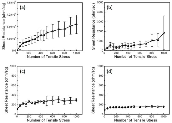
Figure 5.
Sheet resistance of (a) ITO electrode on a PET film, (b) AgNW-exposed electrode on a PET film, (c) AgNW-embedded electrode inside NOA63 and (d) AgNW-embedded electrode inside NOA71 depending on the number of tensile stresses. The bending radius was 4 mm.
To investigate why the ITO electrode on the PET film showed a more significant increase in sheet resistance than the AgNW-based electrodes when applying tensile stress, and why the sheet resistance significantly increased under the application of tensile stress compared to compressive stress, the morphology of the ITO electrodes was examined via SEM and AFM before and after applying tensile stress 1000 times (Figure 6). Although the ITO surface did not have any cracks or defects before the application of tensile stress, a large crack was observed on it after the application of tensile stress. While the cracks were not wide and the ITO was slightly connected across the cracks under the application of compressive stress, the cracks were very wide and the ITO was completely separated because of the cracks under the application of tensile stress. The AFM images indicated that tensile stress increased the RMS roughness of the ITO electrode. The RMS roughness of the ITO electrode was 1.9 nm prior to applying the tensile stress and 13.2 nm after applying the tensile stress 1000 times. When comparing the application of compressive stress, the RMS roughness increased less with the application of tensile stress. When a compressive stress was applied, the two areas divided by the crack pushed each other upward, resulting in a rough surface. In the case of tensile stress application, the two areas do not have the force to push each other upward. There is only force to enable the two areas to move away from each other, resulting in a relatively small increase in the RMS roughness. In addition, both the SEM and AFM images indicate that tensile stress generated large cracks on the ITO surface and significantly increased the sheet resistance compared to that observed when compressive stress was applied, and the ITO was completely separated into two regions by the cracks. Figure 7 shows the SEM and AFM images of the AgNW-exposed electrode before and after applying tensile stress. The SEM image of the AgNW-exposed electrode shows no noticeable cracks, unlike the ITO electrode on the PET film. However, similar to the application of compressive stress, the AgNWs were broken locally. The AFM images show a different trend from that observed when compressive stress is applied. The RMS roughness remained similar, regardless of the application of tensile stress. The RMS roughnesses were 9.8 nm and 9.4 nm before and after applying the tensile stress, respectively. This is because, as in the ITO electrode, the tensile stress did not generate the force required to push the nanowires or the two different regions upward. Consequently, the AgNW-exposed electrode exhibited a smaller sheet resistance increase than that observed in the ITO electrode. In addition, although the application of tensile stress showed little change in the RMS roughness of the AgNW-exposed electrode, the sheet resistance increase was relatively large compared to that observed when compressive stress was applied. The reason is that the driving force to divide the conductive region into two was greater than the compressive stress. The AgNW-embedded electrode exhibited a stable surface morphology, regardless of the application of tensile stress, similar to the application of compressive stress. As shown in Figure 8, regardless of the type of polymer used for the embedding process, there were few cracks or regions where the nanowires were broken. In addition, the RMS roughness was 4.8 nm and 2.5 nm when NOA63 and NOA71 were used as an embedding polymer, respectively, which is similar to that before the application of tensile stress. The AgNW-embedded electrodes showed superior sheet resistance stability compared to ITO electrodes on a PET film and AgNW-exposed electrodes. This was because a AgNW network was formed inside the embedding polymer, regardless of the application of compressive stress or tensile stress.
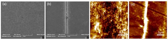
Figure 6.
(a,b) SEM and (c,d) AFM images of the ITO electrode on a PET film (a,c) before and (b,d) after applying tensile stress. The RMS roughness values before and after applying tensile stress were 1.9 nm and 13.2 nm, respectively.

Figure 7.
(a,b) SEM and (c,d) AFM images of the AgNW-exposed electrode on a PET film (a,c) before and (b,d) after applying tensile stress. The RMS roughness values before and after applying tensile stress were 9.8 nm and 9.4 nm, respectively.
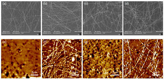
Figure 8.
(a–d) SEM and (e,h) AFM images of the AgNW-embedded electrode in (a,b,e,f) NOA63 and (c,d,g,h) NOA71 (a,c,e,g) before and (b,d,f,h) after applying tensile stress. The RMS roughness values of AgNW-embedded electrode in NOA63 were 3.7 nm and 4.8 nm before and after applying tensile stress, respectively. The RMS roughness values of AgNW-embedded electrode in NOA71 were 1.6 nm and 2.5 nm before and after applying tensile stress, respectively.
To examine how the compressive and tensile stresses affect the light transmittance characteristics, the optical transmittance in the region of 300–800 nm was measured for various electrodes. Figure 9 shows the optical transmittance of the ITO electrode on the PET film, the AgNW-exposed electrode, and the AgNW-embedded electrode before and after the application of compressive and tensile stress. The ITO electrode on the PET film showed an average transmittance of 77.1% before stress application in the visible light region (400–700 nm). After applying compressive and tensile stresses, the transmittance remained at approximately 77%, regardless of the type of stress. This is because the stress generated cracks on the ITO electrode; however, they were not sufficiently large to change the optical reflection. The AgNW-exposed electrode showed a slightly higher transmittance than the ITO electrode before stress application. Specifically, the average transmission in the visible light region was 83.9%. However, after stress application, the average transmittance decreased, reaching 72.8% and 80.6% when compressive and tensile stresses were applied, respectively. It is speculated that the relatively large reduction in transmittance after the application of compressive stress results from a gap between the substrate and the silver nanowire, which is caused by upward pushing or roughness change. In contrast, the AgNW-embedded electrodes showed similar transmittance regardless of the type of polymer used for embedding and the type of stress. When NOA63 was used as the embedding polymer, the average transmittance in the visible light region was 86.7%. When compressive stress or compressive stress was applied, the average transmittance remained approximately 86%. When NOA71 was used as the polymer for the embedding process, the average transmittance in the visible region was 86.3% before stress application and remained 86% even when compressive or tensile stress was applied, indicating that the stress had little effect on the transmittance. This is because stress had little effect on the surface morphology and light reflection, as seen in the SEM and AFM images.
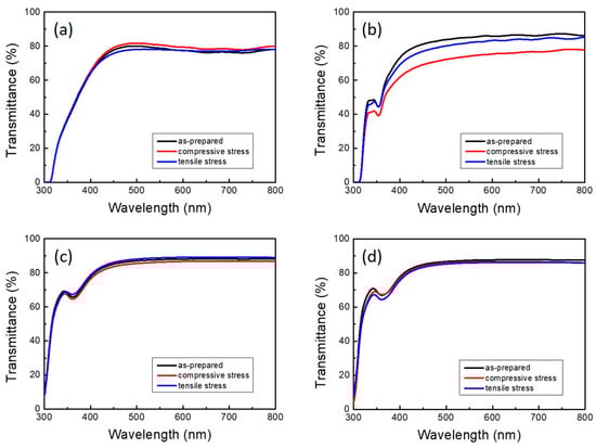
Figure 9.
Optical transmittance of (a) the ITO electrode on a PET film, (b) the AgNW-exposed electrode on a PET film, (c) the AgNW-embedded electrode inside NOA63 and (d) the AgNW-embedded electrode inside NOA71 depending on the number of compressive or tensile stresses. The bending radius was 4 mm.
4. Conclusions
Electrical properties, such as sheet resistance, and optical properties, such as light transmittance, were observed upon the application of compressive and tensile stresses to various types of flexible transparent electrodes. The sheet resistance of the ITO electrode increased to 3173 Ω/sq and 87,833 Ω/sq when compressive and tensile stresses were applied 1000 times, respectively. This is because cracks were generated by the stress, with the crack size being larger under tensile stress. In the AgNW-exposed electrodes, the effect of stress on the sheet resistance was relatively small. Therefore, when compressive and tensile stresses were applied 1000 times, sheet resistances of 1178 Ω/sq and 1856 Ω/sq were observed, respectively. This is because there were few cracks in the AgNW-exposed electrode, and the AgNW was only locally broken or bent. AgNW-embedded electrodes showed the highest sheet resistance stability under all stresses because a AgNW network capable of enabling electron flow was formed inside the polymer; thus, no significant change was generated. In addition, stress had little effect on the transmittance. Therefore, it is concluded that the fabrication of a AgNW-embedded flexible electrode using a flexible polymer is the best method for manufacturing stable electronic devices under both compressive and tensile stresses.
Author Contributions
Y.M., D.K. and J.K. conceived and designed the experiments. Y.M., G.W.S. and D.K. conducted the experiments. Y.M., S.J., D.C.H., J.-S.R. and J.K. analyzed the data and contributed to manuscript preparation. Y.M., D.K. and J.K. wrote the first draft of the manuscript and revised the manuscript. All authors have read and agreed to the published version of the manuscript.
Funding
This research was supported by the National Research Foundation of Korea Grant funded by the Korean Government (NRF-2018R1A6A1A03025761).
Data Availability Statement
The data presented in this study are available on request from the corresponding author. The data are not publicly available due to privacy.
Conflicts of Interest
The authors declare no conflicts of interest.
References
- Kaltenbrunner, M.; Sekitani, T.; Reeder, J.; Yokota, T.; Kuribara, K.; Tokuhara, T.; Michael, D.; Reinhard, S.; Ingrid, G.; Simona, B.; et al. An ultra-lightweight design for imperceptible plastic electronics. Nature 2013, 499, 458–463. [Google Scholar] [CrossRef] [PubMed]
- Wang, P.; Hu, M.; Wang, H.; Chen, Z.; Feng, Y.; Wang, J.; Ling, W.; Huang, Y. The evolution of flexible electronics: From nature, beyond nature, and to nature. Adv. Sci. 2020, 7, 2001116. [Google Scholar] [CrossRef] [PubMed]
- Wang, J.; Hassan, M.; Liu, J.; Yu, S. Nanowire assemblies for flexible electronic devices: Recent advances and perspectives. Adv. Mater. 2018, 30, 1803430. [Google Scholar] [CrossRef] [PubMed]
- Dai, Y.; Hu, H.; Wang, M.; Xu, J.; Wang, S. Stretchable transistors and functional circuits for human-integrated electronics. Nat. Electron. 2021, 4, 17–29. [Google Scholar] [CrossRef]
- Mirshojaeian Hosseini, M.J.; Nawrocki, R.A. A review of the progress of thin-film transistors and their technologies for flexible electronics. Micromachines 2021, 12, 655. [Google Scholar] [CrossRef] [PubMed]
- Shi, W.; Guo, Y.; Liu, Y. When flexible organic field-effect transistors meet biomimetics: A prospective view of the internet of things. Adv. Mater. 2020, 32, 1901493. [Google Scholar] [CrossRef] [PubMed]
- Shin, D.; Jung, D.; Lee, H. Semitransparent solar cells employing n-type graphene on LaVO3. ACS Omega 2023, 8, 18695–18701. [Google Scholar] [CrossRef]
- Song, H.; Ma, Y.; Ko, D.; Jo, S.; Hyun, D.C.; Kim, C.S.; Oh, H.; Kim, J. Influence of humidity for preparing sol-gel ZnO layer: Characterization and optimization for optoelectronic device applications. Appl. Surf. Sci. 2020, 512, 145660. [Google Scholar] [CrossRef]
- Deng, H.; Cheng, Y.; Chen, Z.; Lin, X.; Wu, J.; Zheng, Q.; Zhang, C.; Cheng, S. Flexible substrate-structured Sb2S3 solar cells with back interface selenization. Adv. Funct. Mater. 2023, 33, 2212627. [Google Scholar] [CrossRef]
- Liu, J.; Deng, J.; Zhu, Y.; Geng, X.; Zhang, L.; Jeong, S.Y.; Zhou, D.; Woo, H.Y.; Chen, D.; Wu, F.; et al. Regulation of polymer configurations enables green solvent-processed large-area binary all-polymer solar cells with breakthrough performance and high efficiency stretchability Factor. Adv. Mater. 2023, 35, 2208008. [Google Scholar] [CrossRef]
- Lee, H.B.; Jin, W.Y.; Ovhal, M.M.; Kumar, N.; Kang, J.W. Flexible transparent conducting electrodes based on metal meshes for organic optoelectronic device applications: A review. J. Mater. Chem. C 2019, 7, 1087–1110. [Google Scholar] [CrossRef]
- Park, H.; Chang, S.; Zhou, X.; Kong, J.; Palacios, T.; Gradecak, S. Flexible graphene electrode-based organic photovoltaics with record-high efficiency. Nano Lett. 2014, 9, 5148–5154. [Google Scholar] [CrossRef] [PubMed]
- Chung, W.H.; Jang, Y.R.; Hwang, Y.T.; Kim, S.H.; Kim, H.S. The surface plasmonic welding of silver nanowires via intense pulsed light irradiation combined with NIR for flexible transparent conductive films. Nanoscale 2020, 12, 17725–17737. [Google Scholar] [CrossRef] [PubMed]
- Jung, S.; Lee, S.; Song, M.; Kim, D.; You, D.; Kim, J.; Kim, C.; Kim, T.; Kim, K.; Kim, J.; et al. Extremely flexible transparent conducting electrodes for organic devices. Adv. Energy Mater. 2014, 1, 1300474. [Google Scholar] [CrossRef]
- Lee, H.; Kim, I.; Kim, M.; Lee, H. Moving beyond flexible to stretchable conductive electrodes using metal nanowires and graphenes. Nanoscale 2016, 8, 1789–1822. [Google Scholar] [CrossRef]
- Nowicka, A.B.; Czaplicka, M.; Kowalska, A.A.; Szymborski, T.; Kamińska, A. Flexible PET/ITO/Ag SERS platform for label-free detection of pesticides. Biosensors 2019, 9, 111. [Google Scholar] [CrossRef]
- Lee, J.R.; Lee, D.Y.; Kim, D.G.; Lee, G.H.; Kim, Y.D.; Song, P.K. Characteristics of ITO films deposited on a PET substrate under various deposition conditions. Met. Mater. Int. 2008, 14, 745–751. [Google Scholar] [CrossRef]
- Bazargan, A.M.; Sharif, F.; Mazinani, S.; Naderi, N. A high quality ITO/PET electrode for flexible and transparent optoelectronic devices. J. Mater. Sci. Mater. 2017, 28, 2962–2969. [Google Scholar] [CrossRef]
- Hao, L.; Diao, X.; Xu, H.; Gu, B.; Wang, T. Thickness dependence of structural, electrical and optical properties of indium tin oxide (ITO) films deposited on PET substrates. Appl. Surf. Sci. 2018, 254, 3504–3508. [Google Scholar] [CrossRef]
- Tseng, K.S.; Lo, Y.L. Effect of sputtering parameters on optical and electrical properties of ITO films on PET substrates. Appl. Surf. Sci. 2013, 285, 157–166. [Google Scholar] [CrossRef]
- Angmo, D.; Krebs, F.C. Flexible ITO-free polymer solar cells. J. Appl. Polym. Sci. 2013, 129, 1–14. [Google Scholar] [CrossRef]
- Azani, M.R.; Hassanpour, A.; Torres, T. Benefits, problems, and solutions of silver nanowire transparent conductive electrodes in indium tin oxide (ITO)-free flexible solar cells. Adv. Energy Mater. 2020, 10, 2002536. [Google Scholar] [CrossRef]
- Lee, T.; Choi, Y.W.; Lee, G.; Pikhitsa, P.V.; Kang, D.; Kim, S.M.; Choi, M. Transparent ITO mechanical crack-based pressure and strain sensor. J. Mater. Chem. C 2016, 4, 9947–9953. [Google Scholar] [CrossRef]
- Ahn, Y.; Jeong, Y.; Lee, Y. Improved thermal oxidation stability of solution-processable silver nanowire transparent electrode by reduced graphene oxide. ACS Appl. Mater. Interfaces 2012, 4, 6410–6414. [Google Scholar] [CrossRef]
- Liu, Y.; Xu, X.; Wei, Y.; Chen, Y.; Gao, M.; Zhang, Z.; Si, C.; Li, H.; Ji, X.; Liang, J. Tailoring silver nanowire nanocomposite interfaces to achieve superior stretchability, durability, and stability in transparent conductors. Nano Lett. 2022, 22, 3784–3792. [Google Scholar] [CrossRef]
- Mayousse, C.; Celle, C.; Fraczkiewicz, A.; Simonato, J.P. Stability of silver nanowire based electrodes under environmental and electrical stresses. Nanoscale 2015, 7, 2107–2115. [Google Scholar] [CrossRef]
- Leem, D.S.; Edwards, A.; Faist, M.; Nelson, J.; Bradley, D.D.C.; Mello, J.C. Efficient organic solar cells with solution-processed silver nanowire electrodes. Adv. Mater. 2011, 23, 4371. [Google Scholar] [CrossRef]
- Lee, D.J.; Oh, Y.; Hong, J.M.; Park, Y.W.; Ju, B.K. Light sintering of ultra-smooth and robust silver nanowire networks embedded in poly (vinyl-butyral) for flexible OLED. Sci. Rep. 2018, 8, 14170. [Google Scholar] [CrossRef]
- You, B.; Han, C.J.; Kim, Y.; Ju, B.K.; Kim, J.W. A wearable piezocapacitive pressure sensor with a single layer of silver nanowire-based elastomeric composite electrodes. J. Mater. Chem. A 2016, 4, 10435–10443. [Google Scholar] [CrossRef]
- Zhang, Y.; Guo, J.; Xu, D.; Sun, Y.; Yan, F. One-pot synthesis and purification of ultralong silver nanowires for flexible transparent conductive electrodes. ACS Appl. Mater. Interfaces 2017, 9, 25465–25473. [Google Scholar] [CrossRef] [PubMed]
- Sim, H.; Kim, C.; Bok, S.; Kim, M.K.; Oh, H.; Lim, G.; Cho, S.M.; Lim, B. Five-minute synthesis of silver nanowires and their roll-to-roll processing for large-area organic light emitting diodes. Nanoscale 2018, 10, 12087–12092. [Google Scholar] [CrossRef]
- Ko, D.; Gu, B.; Kang, S.J.; Jo, S.; Hyun, D.C.; Kim, C.S.; Kim, J. Critical work of adhesion for economical patterning of silver nanowire-based transparent electrodes. J. Mater. Chem. A 2019, 7, 14536–14544. [Google Scholar] [CrossRef]
- Chen, D.; Zhao, F.; Tong, K.; Saldanha, G.; Liu, C.; Pei, Q. Mitigation of electrical failure of silver nanowires under current flow and the application for long lifetime organic light-emitting diodes. Adv. Electron. Mater. 2016, 2, 1600167. [Google Scholar] [CrossRef]
- Song, Y.; Cho, J. Interfacial control and design of conductive nanomaterials for transparent nanocomposite electrodes. Nanoscale 2020, 12, 20141–20157. [Google Scholar] [CrossRef]
Disclaimer/Publisher’s Note: The statements, opinions and data contained in all publications are solely those of the individual author(s) and contributor(s) and not of MDPI and/or the editor(s). MDPI and/or the editor(s) disclaim responsibility for any injury to people or property resulting from any ideas, methods, instructions or products referred to in the content. |
© 2024 by the authors. Licensee MDPI, Basel, Switzerland. This article is an open access article distributed under the terms and conditions of the Creative Commons Attribution (CC BY) license (https://creativecommons.org/licenses/by/4.0/).