1. Introduction
In the last two decades, analog broadcasting has been progressively replaced by digital modulation, which allows the use of advanced video compression techniques for terrestrial TV, resulting in a significant increase in the quality of the transmitted video signal, also improving the allocation efficiency of the frequency spectrum. Digital TV (DTV) offers the final user a high data rate transmission, it provides interactive services, and it is able to operate at lower power compared to analog TV. The DTV operates in the UHF band, from Channel 21 to Channel 69 (470 MHz–860 MHz) [
1], and, being a broadcast service, it is employed by a large user base. Therefore, the rapid evolution of the digital TV calls for high-performance, broadband, and low-cost antennas working in the lowest part of the UHF band.
Log-Periodic Dipole Arrays (LPDAs) have been the most common and widespread antennas used for TV signal reception since their first introduction in the 1960s [
2], thanks to their wideband properties and flat gain within their operating frequency band and they are still considered one of the best solutions for all applications that require a broadband behavior and a stable gain [
3,
4]. Wire LPDAs using cylindrical dipoles as radiating elements were proposed by DuHamel in 1957 [
5] and are still extensively used as wideband antennas. They can be designed with a bandwidth up to a decade, with a typical gain of around 10 dBi in air [
6], and can be used at VHF and UHF frequencies, with a standard and cost-effective technology. Standard wire LPDAs can be designed following Carrel’s guidelines [
7] and can be fabricated relying on relatively low-cost procedures. However, the main advantages of wire LPDAs are lost in the SHF band, where the dipoles become so short and tiny that they can be created only by specialized technologies [
8]. On the other hand, printed LPDAs are a common choice for applications in the SHF band and beyond, due to their low production cost, size, and weight. Printed LPDAs can be miniaturized using suitable dielectric substrates since the resonant length of the printed dipoles must be equal to half a wavelength in the dielectric substrate. This feature of printed LPDAs can also be exploited to design a compact and low-cost printed LPDA at UHF frequencies, as we performed in this paper. A further miniaturization can be easily achieved in printed LPDAs by suitably meandering the radiating dipoles, leading to a designed antenna with a reduced size, especially compared with the corresponding wire antenna working in the same frequency band.
The typical size of wire log-periodic dipole arrays that cover the frequency band of analog TV is almost 1 square meter, and the operating bandwidth spans from 300 MHz to 1 GHz. Therefore, such wire LPDAs could be cumbersome in the DTV-UHF frequency band [
9,
10], but their size can be reduced by employing printed LPDAs, which exploit planar technology to reduce the dipole length. Since the dipole arms of such LPDAs are printed on the opposite sides of a dielectric substrate, the geometrical parameters of such an antenna cannot be computed in the same way as a standard wire LPDA [
7]. In particular, the length of the longest dipole must be computed by considering the dielectric substrate parameters [
11], and then the rest of the dipoles can be designed following Carrel [
7], choosing first the optimal values for the log-period τ and the spacing factor σ, and then obtaining the necessary number of dipoles to cover the requested frequency band.
The dielectric substrate of the printed LPDA for DTV applications must be as cheap as possible since the antenna size is relatively large to cover the requested UHF bandwidth; therefore, the best choice is an FR4 substrate, which has a dielectric permittivity of around 4.3, guaranteeing a moderate size reduction at a low cost. A further size reduction can be achieved using one of the many techniques proposed in the literature for reducing the size of an LPDA [
12]. Such techniques include using different shapes for the LPDA dipoles [
13,
14,
15,
16], using fractal layouts for the dipoles to increase the total length of the current path [
17,
18], reducing the axial size of the LPDA by reducing the boom length [
19], or using the dielectric-loading technique [
20], which can be applied both to wire LPDAs [
13,
15] and printed LPDAs [
14,
16,
17,
18,
19,
20].
The aim of this paper is to propose a compact and low-cost printed LPDA for DVB-T2 Digital TV applications, covering the whole DVB-T2 UHF band from Channel 21 to Channel 69 (470 MHz–860 MHz). This solution has been achieved by exploiting both the use of a dielectric substrate and the shaping of the radiating dipoles. An FR4 substrate has been chosen since it is one of the cheapest available in the market, and the antenna size has been confined to an A4 sheet dimension, which is the most common and cheapest format of FR4 sheets with a double metal cover. Moreover, the A4 format is also the typical dimension of the working plane of most of the milling machines for the creation of printed circuits, and this reduces the overall production costs.
To the best of the authors’ knowledge, the solution presented here is not available in the literature, wherein only a few wire LPDAs for DTV in the UHF frequency band can be found [
9,
10]. In comparison with these wire LPDAs, the printed LPDA proposed here allows a compact structure, with a significant reduction in the planar size (see, e.g., the wire LPDA in [
9], wherein the planar size is 302.6 mm × 356 mm vs. 208 mm × 289.5 mm of the antenna in this work).
As summarized in
Table 1, these wire LPDAs have a large size and a higher production cost compared to our proposed solution, which is designed on an FR4 dielectric substrate and fits in an A4 size. Our solution also offers a compact size compared to similar printed LPDAs [
4,
11,
14,
16,
17,
19,
20,
21], with a normalized area of only 0.26 λ
2 (where λ is the free-space wavelength at the central frequency) and a similar (or higher) average gain. Therefore, it is an effective and high-performing LPDA for DTV applications and a valid alternative to the most common wire LPDAs.
It should be remarked that LPDA miniaturization within the UHF band in a limited space such as an A4 sheet is not trivial. Hence, a moderate meandering of the radiating dipoles has been implemented to suitably reduce the vertical size. This will obviously increase the dipoles’ horizontal size, resulting in a stronger coupling between adjacent dipoles. Therefore, an adequate compromise must be found between the size reduction and the antenna performance. The final design covers the requested bandwidth with a satisfactory far-field pattern in both E- and H-planes and a reasonably flat gain, fulfilling all the specifications of a receiving antenna for DTV services.
The proposed LPDA array has been designed using CST Microwave Studio 2023, a general-purpose software for the 3D electromagnetic simulation of microwave components. CST has been a well-assessed and established electromagnetic software for more than two decades, and its results can be considered equivalent to experiments, as reported in the open literature for a wide range of applications (see, for example, [
12,
22,
23,
24,
25,
26,
27]). Therefore, we relied on CST for assessing the LPDA performance.
2. LPDA Design
The proposed printed LPDA for DVB-T2 Digital TV applications has been designed starting from standard Carrel design equations [
7] with some modifications [
4]. In fact, since the printed LPDA lies on a dielectric substrate, the geometric parameters of this antenna cannot be computed as in the case of a standard wire LPDA [
7], which radiates in free space. Hence, the resonant length of the largest printed dipole at the lowest operating frequency is computed by using CST Studio Suite, a general-purpose software for the simulation and design of 3D electromagnetic components, whose results are in excellent agreement with experimental results [
4,
11].
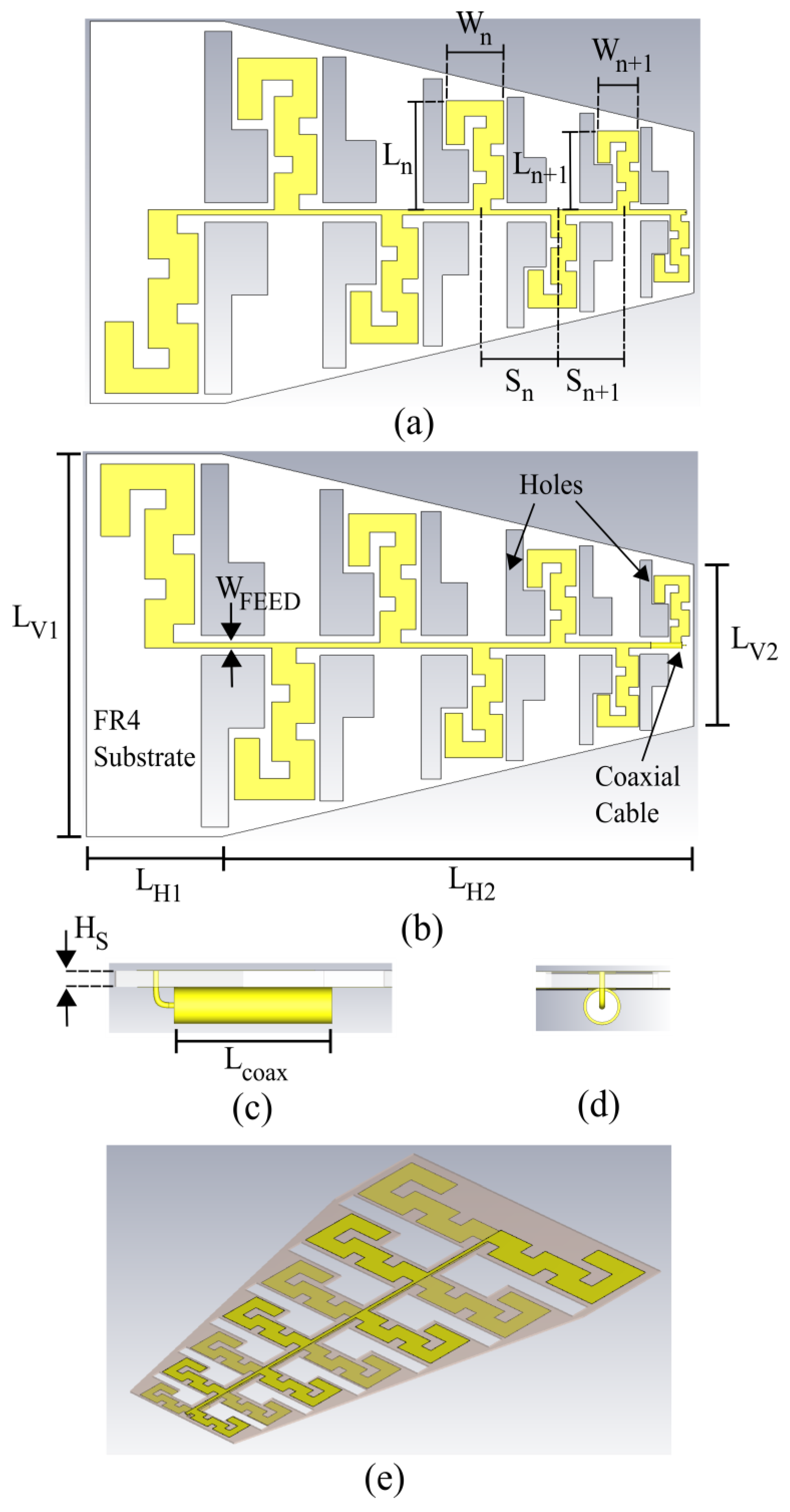
The final layout of the proposed printed LPDA is shown in
Figure 1. The shaped dipoles are, as usual, alternately connected on the two sides of the paired strip feeding line. The paired strip is adequately connected to a coaxial cable, whose outer conductor is soldered to the dipoles’ arms attached to the bottom face of the dielectric substrate, whereas the inner conductor is connected through a via to the dipole arms attached to the upper face of the substrate. This allows all the radiating elements to be fed with alternate signs, giving the LPDA the end-fire behavior.
The structure of the printed LPDA is very close to a standard wire LPDA; thus, we can apply the standard strategy [
7] for estimating the antenna directivity and the required number of radiating dipoles to cover a specified frequency band. The antenna’s operating bandwidth and directivity are the design specifications of the proposed LPDA, and the design parameters are the log-period
τ and the spacing factor
σ, which can be chosen by using Carrel’s design curves [
7].
The printed LPDA design steps are summarized in the following:
- (1)
Select the LPDA’s desired operating frequency band and maximum directivity;
- (2)
Choose the desired values of the log-period
τ and the spacing
σ from Carrel’s design curves [
7];
- (3)
Compute the required number N of LPDA elements to cover the frequency band selected in step 1 using Carrel expressions [
7];
- (4)
Determine the length of the longest dipole (which covers the lowest part of the frequency band) using CST Studio Suite (as described in [
21,
28]);
- (5)
Determine the parameters of the N-1 remaining dipoles of the LPDA scaling by
τi−1 (
i = 2, …,
N) the parameters of the longest dipole designed in step 4 [
7,
21,
28].
In our design, we choose a relatively low value of
τ = 0.85 to limit the number of dipoles necessary to cover the requested frequency band and, hence, the antenna size. Following Carrel’s design curves [
7], the optimal value of
σ should be around 0.15, but this value would result in an excessively large LPDA, which would not fit in the A4 size. Therefore, we have used
σ equal to 0.11. With the selected values of
τ = 0.85 and
σ = 0.11, the maximum directivity
D predicted by Carrel should be around 8 dBi. However, Carrel’s curves are applied to a wire LPDA, whereas for a printed one, lower values are expected [
4,
11,
21,
28]. In fact, the directivity
D achieved by our designed antenna is about 7 dBi.
The operating frequency band of our antenna is 470–860 MHz, with
τ = 0.85 and
σ = 0.11. Then, the estimation of the number of elements of the LPDA antenna can be obtained using the expressions given by Carrel [
7]:
where B
AR is the bandwidth of the active region, B is the antenna’s operating bandwidth, and α is the log-periodic antenna aperture angle. The corresponding value N = 7.55 obtained in (4) must be an integer; therefore, we estimate that 7 elements are required to fulfill the requirements of directivity and bandwidth using the standard approach for the design of wire LPDAs.
Since the printed LPDA lies on a dielectric substrate, its geometric parameters cannot be calculated in the same way as a standard wire LPDA [
7], because their values are strictly related to the substrate on which the radiating dipoles are printed. We have used here a 1.53 mm thick FR4 dielectric substrate, a very low-cost material with a dielectric permittivity of 4.3 and a loss tangent of 0.025. The thickness of the metallization is 35 µm.
The requested input impedance for receiving antennas in TV applications is equal to 75 Ω; therefore, the characteristic impedance of the paired strip feeding line must be 75 Ω, which corresponds to a strip width of W
FEED = 2.69 mm [
21,
28].
At the lowest operating frequency (470 MHz), the active region includes substantially only the longest dipole, which must be designed to resonate at this frequency. Since the resonant resistance of this dipole must be 75 Ω, both its width and length have been selected through a cut-and-try procedure using CST Studio Suite [
21,
28]. We obtain L
DS = 124 mm and W
D = 13.8 mm for a standard printed dipole (
Figure 2b). Hence, the standard dipole requires a total size of L
tot = 2 × L
DS + W
FEED = 2 × 128 mm + 2.69 mm = 250.69 mm, which is significantly larger than the vertical A4 dimension of 210 mm, making it impossible to fit the LPDA, designed with standard printed dipoles as radiating elements, in the A4 size.
The printed dipole has been therefore adequately shaped by meandering its length, obtaining the layout shown in
Figure 2a. The width chosen is equal to the standard dipole, W
D = 13.8 mm, and the dipole shape has been modified to resonate at 470 MHz with a vertical size fitting the A4 dimension of 210 mm and a resistance of 75 Ω. The resulting meandered dipole has a layout with a vertical size of each arm equal to 97.5 mm, whereas all the other dimensions are reported in the caption of
Figure 2. The overall dipole size, considering the distance between its arms (equal to the paired strip width W
FEED) is 197.69 mm, leaving about 6 mm from the vertical borders of the dielectric substrate. The selected shape for the meandered dipole shown in
Figure 2a presents, for each arm, one vertical meander (the path W
D2–L
D7–W
D2 in
Figure 2a) and a U-turn (the path L
D3–L
D2–L
D1 in
Figure 2a), whose arm L
D1 can be chosen to accurately tune the resonant frequency of the dipole. The horizontal depth of the vertical meander W
D2 must be chosen to achieve an adequate reduction in the vertical size of the dipole. However, a compromise should be made since a too-large value of W
D2 will produce a degradation of the dipole matching and radiation pattern and a stronger coupling between the adjacent dipoles of the LPDA.
The reflection coefficients of the two dipoles are shown in
Figure 3. The frequency response is very similar, but the meandered dipole has a narrower −10 dB bandwidth due to the electric and magnetic energy stored in the meanders, which increase the antenna Q factor, and hence decrease its percentage bandwidth. In addition, the far-field pattern at the resonant frequency of 470 MHz, shown in
Figure 4, is substantially equivalent for the meandered and standard dipoles, with a broadside gain equal to 1.85 dBi and 2 dBi, and a 3dB beamwidth equal to 84.5° and 79.5°, respectively.
Once the length
L1 = LDS and width
W1 = WD of the longest printed dipole have been chosen, the lengths and widths of the other dipoles composing the LPDA are computed by using the following expressions [
7,
21,
28]:
n = 1, …, N − 1
With
σ = Sn/4Ln, and
W1 = WD = 13.8 mm in our case, the minimum spacing required for accommodating
N = 7 standard printed dipoles (where
N = 7 is the estimated number of elements computed in (4) necessary to fulfill the requirements on directivity and bandwidth) is equal to:
Hence, a printed LPDA using standard dipoles will exceed both the vertical and horizontal dimensions of an A4 sheet. However, using meandered dipoles as radiating elements will also reduce the horizontal size of the LPDA, allowing the array to fit in an A4 size. Looking at the layout of the proposed printed LPDA in
Figure 1, the distance
Sn between two adjacent dipoles is computed from their medium point, as indicated, and it must be obtained using the same formula as standard dipoles, i.e.,
Sn = 4σLn, where
Ln is the vertical length of the
nth dipole. Since the dipole is meandered, its vertical length, in this case, is significantly smaller if compared to the standard dipole (97.5 mm vs. 124 mm), and this results in a smaller inter-distance between the dipoles and a smaller size of the whole LPDA, which can be computed as
The longest dipole of the LPDA array of
Figure 1 has the geometrical parameters reported in the caption of
Figure 2. The other design parameters of the LPDA antenna are obtained by (5), once S
1 is computed as
S1 = 4
σL1, where
L1 is the vertical length of the shaped meandered dipole, equal to 97.5 mm in our case. The spacings, vertical lengths, and widths of the LPDA layout shown in
Figure 1 are summarized in
Table 2.
3. Results
The final layout of the designed LPDA antenna is shown in
Figure 1. Since the typical installation of receiving television antennas is outdoors, such antennas are subjected to extremely variable weather conditions. In particular, they could be exposed to moderate or even strong wind during normal working conditions. Hence, we have designed holes in the dielectric substrate at each inter-space between the radiating dipoles to increase the wind resistance of the LPDA (as indicated in
Figure 1). The presence of the holes creates a passage for the wind through the antenna, preventing oscillations and folds, which in the long run could move the antenna from its optimal position, or deform or even break the structure, thus creating significant reception problems until service interruption. Moreover, since we positioned these holes in a strategic region, where the electric field is very low (i.e., the inter-space between the dipoles), they have only a negligible effect on the antenna performance. The frequency response of the input reflection coefficient of the designed printed LPDA antenna for DVB-T2 Digital TV applications is shown in
Figure 5. The broadband input matching specification between 470 and 860 MHz (percentage bandwidth of 60%) is completely fulfilled, with the matching extending well beyond the requested range. The 10 dB antenna bandwidth approximately extends from 450 to 940 MHz (≈74%), covering the whole DVB-T2 UHF band from Channel 21 to Channel 69. The satisfying frequency behavior of the proposed compact low-cost LPDA antenna is confirmed by the antenna input impedance reported in
Figure 6, where both real and imaginary parts are relatively flat within the specified frequency band, ensuring a good matching with the requested reference impedance for Digital TV Applications, equal to 75 Ω.
In
Figure 7, the LPDA antenna directivity, gain, and radiation efficiency are reported as a function of the frequency. The LPDA gain and directivity are quite stable over the required frequency range, and their average values are equal to 6.56 dB and 6.75 dB, respectively. The predicted reduction in the directivity and gain in comparison with a standard wire LPDA with the same values of
τ = 0.85 and
σ = 0.11 is confirmed by these results. Moreover, we used meandered dipoles as radiating elements instead of standard printed dipoles, and this resulted in a further small decrease in the value of D, as already discussed when comparing the far fields of the isolated dipoles reported in
Figure 4. Finally, the radiation efficiency of the proposed antenna is excellent within the operating frequency band, with a flat behavior and an average value above 97%.
Finally,
Figure 8 reports the E-plane and H-plane radiation patterns at 470 MHz, 860 MHz, and 665 MHz, i.e., at the center frequency and at the extremes of the requested frequency band. The cross-polar component is more than 30 dB below the co-polar one in the E-plane, and more than 40 dB lower in the H-plane. Comparing the radiation performance of the wired LPDAs and printed LPDAs of
Table 1 that are implemented using traditional dipoles with our printed LPDA with meandered dipoles, we can conclude that the printed LPDA proposed here shows substantially the same radiation pattern and similar levels of cross-polar components. The far-field pattern shows a satisfying end-fire behavior in the whole DVB-T2 UHF band, confirming that the proposed LPDA can be successfully used as a compact low-cost broadband antenna for Digital TV applications in the frequency range 470–860 MHz, with a fractional bandwidth greater than 70%.


