Article

Development of Grouting Test System for Rough Fissure Rock Body and Research on Slurry Diffusion Law

1
School of Energy Science and Engineering, Henan Polytechnic University, Jiaozuo 454003, China
2
Collaborative Innovation Center of Coal Work Safety and Clean High Efficiency Utilization, Jiaozuo 454003, China
3
Henan Mine Water Disaster Prevention and Control and Water Resources Utilization Engineering Technology Research Center, Henan Polytechnic University, Jiaozuo 454003, China
4
School of Civil Engineering, Henan Polytechnic University, Jiaozuo 454003, China
*
Author to whom correspondence should be addressed.
Appl. Sci. 2024, 14(1), 47; https://doi.org/10.3390/app14010047
Submission received: 28 August 2023 / Revised: 8 November 2023 / Accepted: 23 November 2023 / Published: 20 December 2023

Abstract

:
The surface roughness of grout in fractured rock masses has a significant impact on the diffusion characteristics of grout, especially in millimeter-scale fractures. In this study, a self-constructed experimental system for grouting in rough fractured rock masses was used to conduct grout diffusion tests with varying fracture roughness, fracture aperture, and grouting pressure. A theoretical model was developed to account for the combined effects of fracture roughness, aperture, and grouting pressure on grout diffusion, and its validity was verified. The results showed that the theoretical calculations and experimental results had an error rate of around 12%, indicating the high reliability of the theory. Fracture aperture, grouting pressure, and fracture roughness all exhibited nonlinear relationships with the grout pressure distribution. With increasing diffusion distance, the grout pressure decreased, and the rate of decrease gradually slowed down. Fracture roughness and aperture had a relatively small impact on grout pressure, while grouting pressure had a significant influence on grout pressure distribution. The difference in grout pressure between the initial and final stages of diffusion was small, whereas in the middle stage of diffusion, the difference was more pronounced. This research provides a valuable reference for the selection of grouting techniques in the roadway surrounding rock projects.

1. Introduction

In the process of excavating and unloading coal mine tunnels, a large number of intricate and complex fractures develop within the surrounding rock, leading to a reduction in the rock’s inherent strength, increased permeability, and a heightened susceptibility to instability and failure, thereby compromising the stability and safety of the surrounding rock [1,2]. To meet the requirements of on-site coal mining projects, grouting is employed in fractured rock masses to enhance rock strength and reduce permeability [3,4,5]. Given the limited space within tunnel surroundings and the relatively small fracture apertures, the influence of fracture roughness, aperture, and grouting pressure on grout diffusion cannot be overlooked. Therefore, it is essential to conduct research on the impact of fracture parameters on grout diffusion.
Relevant scholars have conducted a significant amount of meaningful research on the flow and diffusion of grout in fractures. Weng et al. [6] conducted seepage tests on fractured sandstone using low-field nuclear magnetic resonance technology, analyzing the influence of temperature and pressure on grout flow velocity. Zhang et al. [7] investigated the impact of factors such as fracture distribution, water pressure, and grout properties on grout diffusion, and analyzed the variations in rock elastic modulus following grouting with respect to grout viscosity. Researchers [8,9,10,11,12] have explored the influence of grout properties, grouting time, injection pressure, and fracture inclination on the grout diffusion distance. Liang et al. [13] employed the finite element level set method to study the relationship between grout diffusion range and grouting time, as well as the variations in grout pressure over time. Du et al. [14] observed that when the grout diffusion distance falls within the range of from 0.3 m to 0.4 m, the grout injection pressure required at a low velocity is greater than that required at a high velocity. Mu et al. [15,16] divided the grout flow region into a stagnant zone, transition zone, and breakthrough zone, with grouting pressure increasing as the fracture roughness increased. Mohammadmoradi et al. [17] simulated the fluid flow and transport phenomena through millimeter-sized three-dimensional plates and investigated the effects of the degree of homogeneity of the fluid and the injection rate on its longitudinal dispersion coefficient. Sample-Lord et al. [18] analyzed the role of chloride ions in the slurry on the apparent diffusion coefficient, which changed relatively little with higher chloride concentrations. Xuan et al. [19] divided the grout diffusion process into the diffusion stage and the consolidation stage, suggesting that the consolidation stage is the key phase controlling the mud diffusion radius. Zhong et al. [20] used fluid equations and a grout diffusion model to derive fluid diffusion equations and analyze the diffusion mechanisms of grout within rock masses. Bai et al. [21] analyzed the variations in carrier stiffness coefficients due to crack scale and quantified the degree of deterioration. Li et al. [22] investigated the impact of grout flow velocity on its diffusion range and injection pressure. Li et al. [23] found that a higher sand-to-grout ratio results in a better mechanical performance and an increase in the anti-seepage time efficiency of the grout, with injection pressure being the most influential factor in grout diffusion. Jin et al. [24] discussed the effects of fracture roughness, grout flow velocity, and grout setting time on the efficiency of grout sealing in fractures, with flow velocity having the most significant effect. Wang et al. [25] developed a two-stage column-hemispherical diffusion model for Newtonian fluids using fractal theory and considering the curvature of the diffusion path and the time-varying viscosity of the slurry. Ge et al. [26] found that the seepage properties of rocks can be characterized by using the seepage capacity, diffusion rate, etc. Guo et al. [27] concluded that the fracture boundary effect has a non-negligible influence on the slurry diffusion, and obtained the streamline equation for the slurry diffusion trajectory. Pan et al. [28] analyzed the influence of grouting volume, grouting pressure, and other factors on the grout diffusion pattern, concluding that, under different grouting parameters, the grout diffusion radius is directly proportional to the grouting time. Liu et al. [29] developed a novel dynamic grouting test system to study the impact of water flow rate, grout flow rate, and fracture aperture on grout diffusion characteristics, concluding that increasing the grout flow rate and fracture aperture can effectively control fracture formation. Zhou et al. [30] monitored chemical grouting experiments on porous sandstone fractures using low-field nuclear magnetic resonance technology, comparing and analyzing the effects of grouting pressure and fracture inclination on grouting volume, grouting time, and grout permeability. Mu et al. [31] investigated the influence mechanism of fracture roughness on grout flow and diffusion characteristics, finding that pressure gradient and maximum diffusion velocity exhibit a parabolic growth with changes in relative roughness. Jia et al. [32] conducted a study on the influence of slurry temperature on the diffusion range within planar cracks, revealing significant temperature effects that should be considered in the context of grout diffusion.
The current research on the diffusion of slurry in rough rock fractures primarily focuses on the individual influence of single grouting parameters or fracture characteristics. There is a lack of consideration for the comprehensive effects of multiple parameters on slurry diffusion. Through the development of a custom experimental apparatus for slurry diffusion in rough fractures, the diffusion characteristics of slurry in rough fractures were analyzed. Simulation experiments of slurry diffusion under different grouting parameters were conducted. The research findings contribute to an understanding of the diffusion patterns of slurry in fractured rock masses and provide a reliable reference for the selection of grouting processes in different grouting environments.

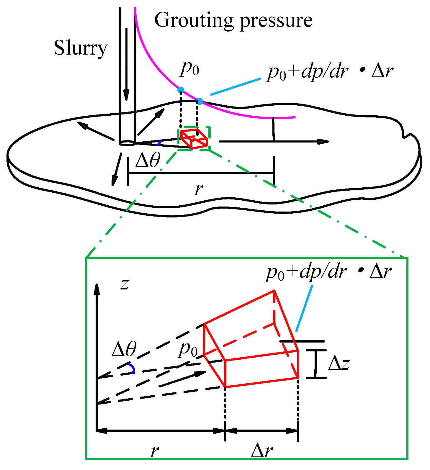
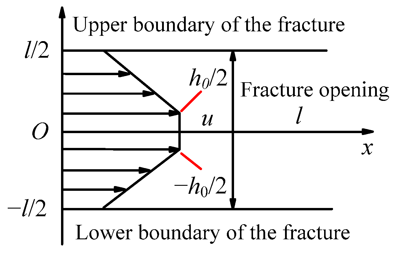
2. Theoretical Analysis of Temporal and Spatial Patterns of Rough Fracture Slurry Pressure

According to related studies [33], slurry with a water–cement ratio ranging from 0.8 to 1.0 behaves as a Bingham fluid, with its viscosity exhibiting time-dependent characteristics, and there are variations in slurry pressure distribution within the diffusion range. A mechanical analysis was conducted of any microelement within the slurry fluid domain [34], and the force diagram for a slurry microelement is shown in Figure 1. From Figure 1, it can be observed that the driving force for the slurry is the grouting pressure, and there is a pressure difference between the front and rear of the microelement, which ensures the continuous flow and diffusion of the slurry.
The time-dependent viscosity of Bingham fluids can be approximated as follows [35]:
μ t = μ 0 + A t B
where μ0 is the initial viscosity of the slurry, mPa·s; A and B are the fitting coefficients, and t is the time, s.
As the velocity is equal everywhere on the microelement, there is a force balance in the direction of motion, and the force equation for the microelement can be expressed as:
p 0 r t l Δ θ Δ z p 0 + d p d r Δ r × r t l + Δ r Δ θ Δ z + p 0 + d p d r Δ r × Δ r Δ z Δ θ + d τ d z Δ z r t l Δ θ + r t l + Δ r Δ θ 2 Δ r = 0
where rtl is the slurry diffusion distance at the slurry flow diffusion time tl; Δr is the slurry diffusion increment at the time increment of Δt; Δθ is the angular increment of the diffusion radius of the micromeres at the time increment of Δt; and Δz is the value of the z-direction coordinates of the micromeres.
Simplifying Equation (2) and omitting the higher-order minutiae yields [35], we can obtain:
d τ d z d p d r = 0
By combining the slurry’s diffusion radius and the constitutive equation, we can integrate these to obtain:
z d p d r = τ 0 + μ d u d z
Since the slurry is of a certain viscosity, the closer it is to the fissure boundary, the lower its flow rate will be. The diffusion pattern of the slurry in the direction perpendicular to the flow is axisymmetric, and the velocity distribution is shown in Figure 2.
From the slurry flow rate distribution diagram, Equation (4) satisfies the following boundary conditions: (i) when |z| = l/2, u = 0; (ii) when |z| ≤ l/2, u = u. Solving for their integrals, ignoring the higher-order minors, there is an average value of the flow rate of the slurry in the fracture as follows:
u ¯ = 1 μ π l r t l 2 u t l τ 0 l 4 l 2 12 d p d r
According to the law of mass conservation, the flow rate of slurry in the rock fractures can be expressed as:
q = 2 π l r u ¯
Combining Equation (4) with Equation (6), the relationship between slurry pressure and diffusion distance is given by:
d p d r = 12 q 2 π l 3 r μ π l r 2 u t l 3 τ 0 l
Integrating Equation (7) and considering the boundary conditions, i.e., r = rtl and p = p0, with p0 being the external standard atmospheric pressure:
p r t l , t = q 2 π l r 0 q t π l 1 r μ π l r t l 2 u t l d r 3 τ 0 l q t π l r + p 0
Combining Equation (1) and Equation (8) and integrating yields:
p r t , t = q A 4 B π l π l q B r t l 2 B r 0 2 B + ln r 0 r t l 3 τ 0 l r t l r 0 + p 0
The flow rate q in the equation needs to be modified when it is used in rough cracks; that is, the slurry flow rate q’ in rough cracks and the slurry flow rate q in smooth cracks meet:
q = λ q
where is the λ flow correction coefficient. Through numerical analysis and joint roughness coefficient (JRC) index, He [36] obtained the correction coefficient expression as follows:
λ = cos 4 0.802 J R C + 3.7412
where JRC is the roughness coefficient of the crack. The grout flow rate q can be calculated according to its velocity, which is solved by Bernoulli’s equation:
p 1 + ρ v 1 2 2 + ρ g h 1 = p 2 + ρ v 2 2 2 + ρ g h 2
π r 1 2 v 1 d t = π r 2 2 v 2 d t
where p1 is the air pressure in the grouting pump, MPa; p2 is the pressure value at the outlet, which is 0.1 MPa; the flow velocity of v1 and v2 represent slurry in the grouting pump and grouting hole, m/s, respectively; h1 and h2 are, respectively, the height of the liquid level of the slurry in the grouting pump and the height of the grouting hole, m; ρj is the slurry density, kg/m3; g is the acceleration of gravity, m/s2.
After the combined calculation, the following can be obtained:
v 2 = 2 r 1 4 p 1 p 2 + ρ g h 1 h 2 ρ r 1 4 r 2 4
Combined with all the above formulas, the spatial and temporal distribution equation of slurry pressure when slurry flows in rough cracks is as follows:
p r t , t = q A cos 4 ( 0.802 J R C + 3.7412 ) 4 B π l π l q B × r t l 2 B r 0 2 B + ln r 0 r t l 3 τ 0 l r t l r 0 + p 0

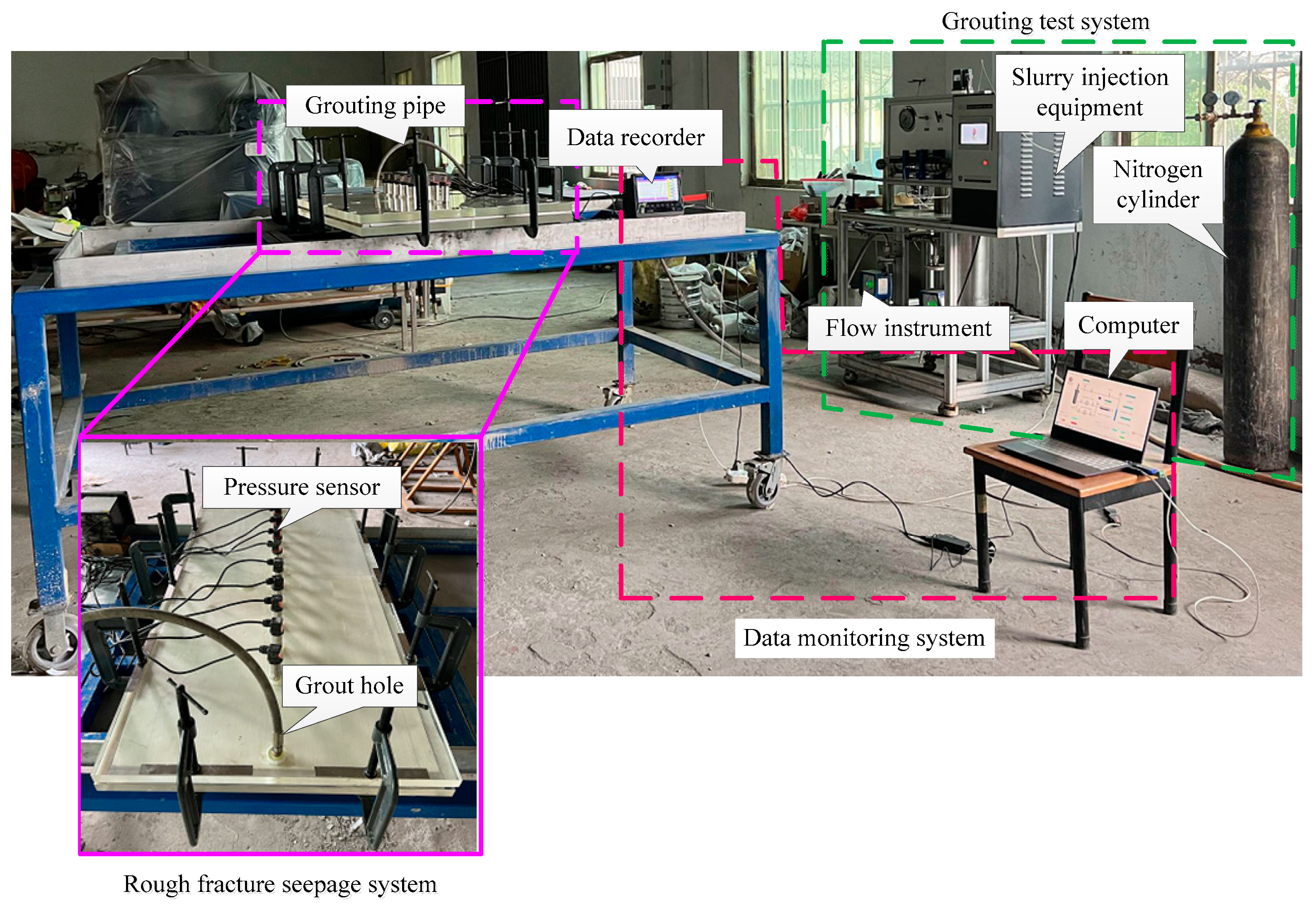
3. Development of a Simulated Grouting Diffusion Experiment Device for Rough Fractures

To better understand the flow behavior of slurry within rock fractures and analyze the variations in slurry pressure according to factors such as grouting pressure, fracture aperture, and fracture roughness, we designed a physical simulation test system for rough fracture grouting. This system primarily consists of three modules: a rock grouting module, a rough fracture seepage module, and a data processing module. The experimental principle is illustrated in Figure 3. The slurry flows into the rough fissure seepage test device through the grouting tank and the grouting pipe under external pressure, and the distribution pattern of the slurry in the diffusion path is monitored by the pressure sensor.

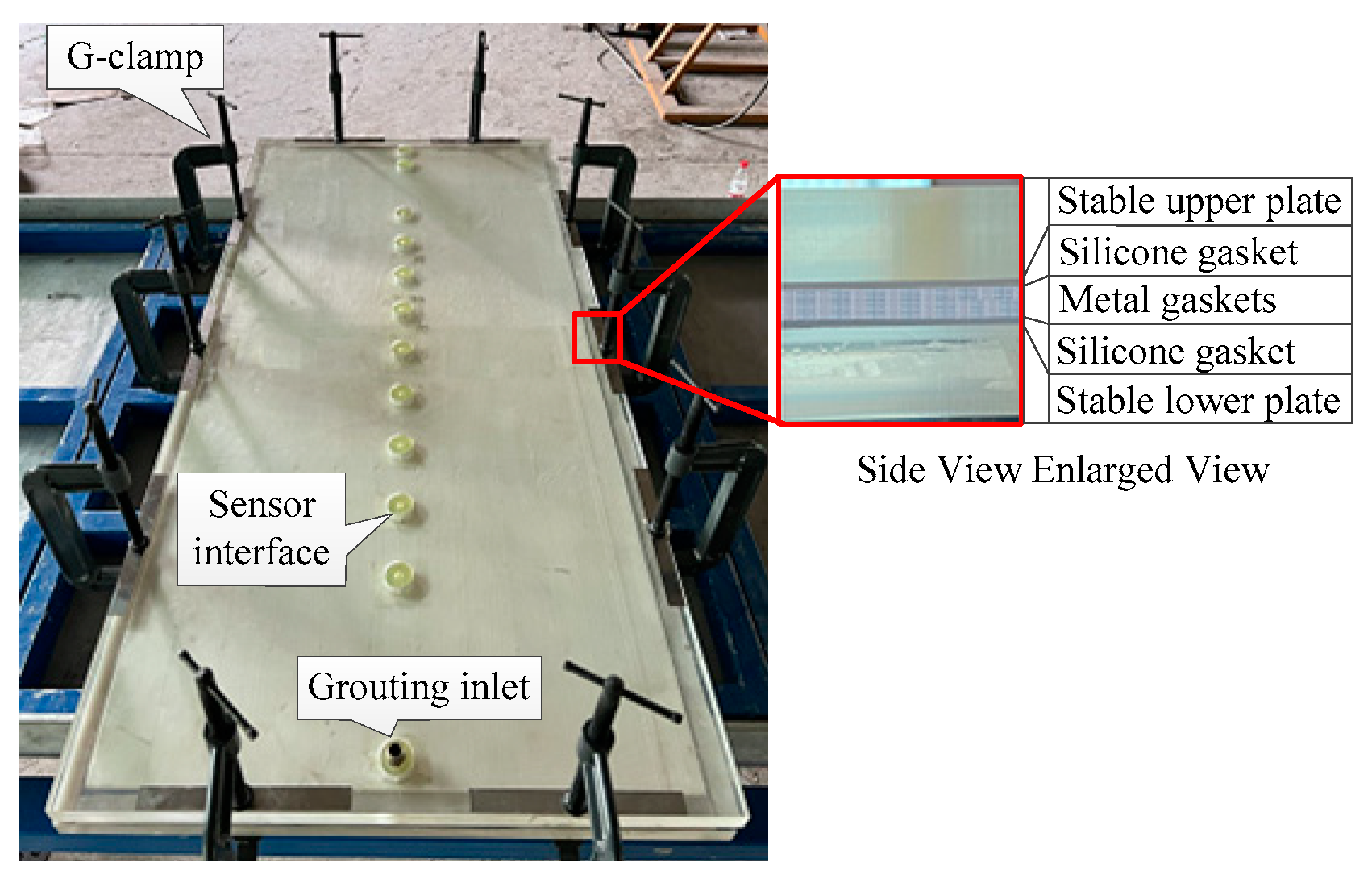
3.1. Rock Grouting Module

The rock grouting module provides the power required for continuous slurry flow, consisting of components such as nitrogen gas cylinders, grouting equipment, and data processing software, as shown in Figure 4. The nitrogen gas cylinder is connected to the grouting equipment through a high-pressure sealed gas line, and it can provide pressure in the range of from 0 to 25 MPa. The data processing software is capable of handling and exporting the experimental data.

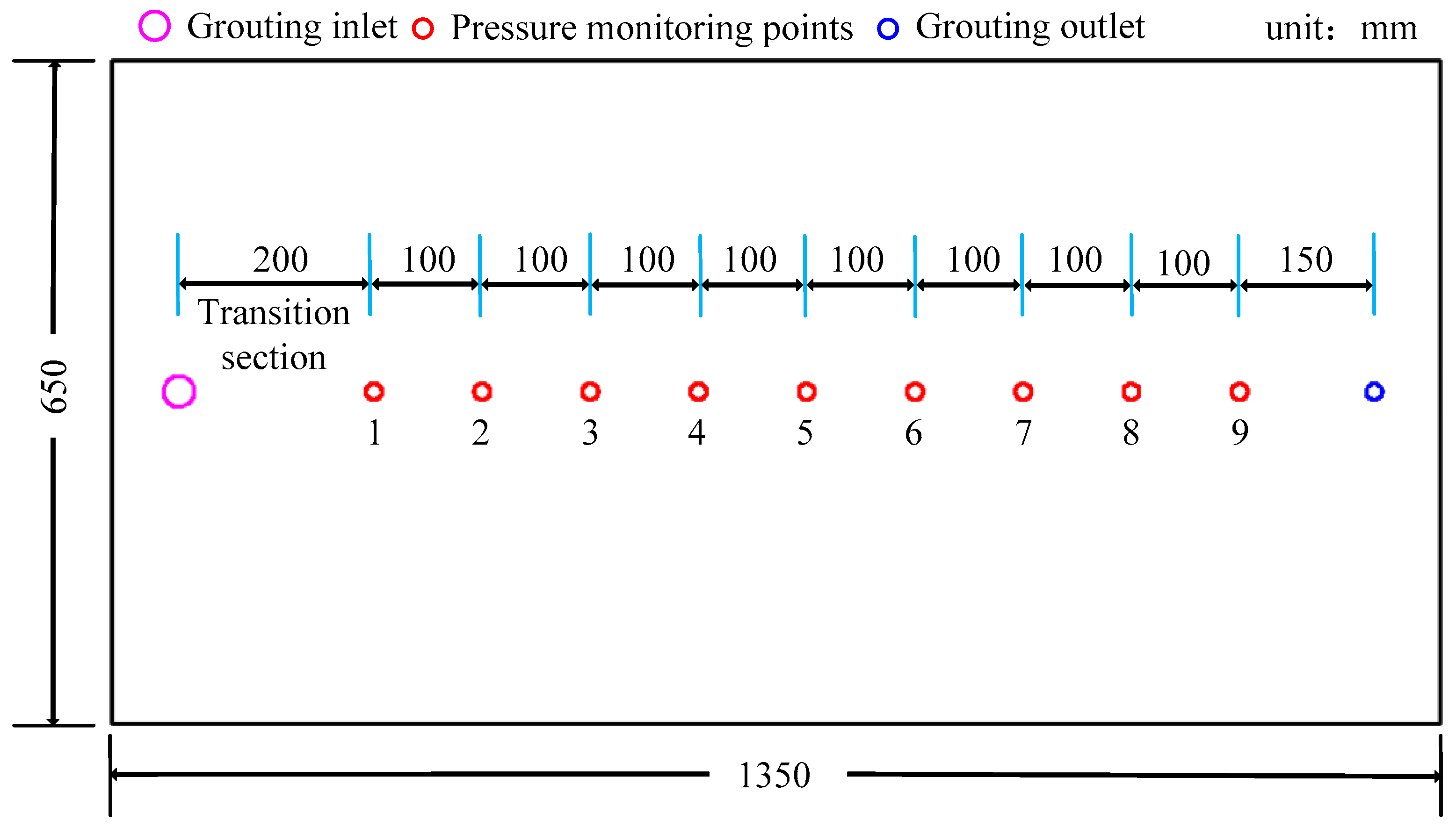
3.2. Rough Fracture Seepage System

The rough fracture seepage system is primarily composed of a stability plate, a rough fracture template, metal shims, G-clamps, silicone gaskets, and other components. The rough fracture template is designed based on the typical curve proposed by scholar Barton, and is created by drawing a three-dimensional image using software and printing it. The specific visual representation can be seen in Figure 5, and the assembled overall appearance of the rough fracture seepage system is shown in Figure 6.

3.3. Data Processing Module

The pressure sensors are installed on the upper plate of the seepage system. To reduce the impact of flow instability when slurry first enters the rough fractures from the grouting pipe on the monitoring of slurry pressure, the first measuring point is located 20 cm away from the grouting hole, and the remaining adjacent measuring holes are spaced 10 cm apart. All measuring holes are positioned along the central axis of the rough fracture template, as shown in the specific arrangement diagram in Figure 7.

3.4. The Technical Advantages of This Experimental System

To investigate the pressure distribution patterns of slurry during its flow and diffusion in rough fractures, a rough fracture grouting test system was designed. A physical representation of this system can be seen in Figure 8. Compared to existing experimental equipment, this test system offers the following technical advantages:
(1)
The existing rough crack test system has a small width and size, as in reference [31]. The entire test setup measures 100 mm × 2 mm; this leads to an approximation of slurry flow as unidirectional, with the presence of boundary layer effects, which significantly deviates from the actual scenario of slurry radially spreading in all directions. Consequently, it is challenging to accurately represent the real on-site slurry diffusion.
(2)
The test system can simulate the flow of different fluids, including slurry, water and air, within rough fractures, and it can also be used to investigate the displacement mechanisms between various fluids.
(3)
The test system can simulate the impact of various parameters, such as different fracture roughnesses, fracture apertures, grouting pressures and fracture inclinations, on the flow behavior of slurry. It has a wide range of applications in experiments.

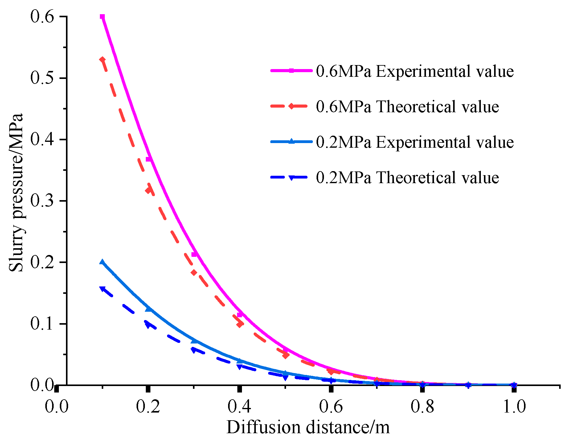
3.5. Reliability Verification of Grouting Test Device

The slurry was cement–sodium silicate slurry, the water–cement ratio was 1:1, and the viscosity time-varying equation was μ(t) = 0.051 + 0.0039t2.13. Before each slurry diffusion test, a water seepage test was carried out to check the tightness of a pipeline connection, and the fracture seepage system was fixed in a horizontal position. Prior to each slurry diffusion test, a water seepage test was conducted to check the sealing of the pipeline connections and ensure the stability of the fracture seepage system in a horizontal position. A flow meter was installed at the outlet of the grouting equipment to provide the real-time monitoring of slurry flow. A pressure control valve was positioned between the nitrogen gas cylinder and the grouting equipment, allowing for the adjustment of grouting pressure as needed for the experiment. After preparing the slurry with a specific water-cement ratio, it was injected through the grouting port into the slurry tank, while simultaneously activating the turbine for slurry agitation. Once the grouting pressure reached the test requirements, the grouting test was initiated, and thereafter, the pressure sensors collected data on the distribution of slurry pressure along the diffusion path. When the slurry achieved a stable flow out of the discharge hole, the current test was concluded, following the specific test plan outlined in Table 1. According to the experimental design, variations in fracture aperture, fracture roughness, and grouting pressure were made, and the above test procedures were repeated to complete the remaining slurry diffusion tests.
To validate the reliability of this test system, experiments were conducted on slurry flow and diffusion in rough fractured rock. The analysis considered the influence of different grouting pressures (0.2 MPa, 0.4 MPa, 0.6 MPa), fracture apertures (2 mm, 4 mm, 6 mm), and JRC values (5.7, 9.8, 13.6, 17.3) on the spatiotemporal distribution of slurry pressure. Due to space constraints, here we present the test results for a fracture aperture of 2 mm and grouting pressures of 0.2 MPa and 0.6 MPa. The pressure at different measuring points over time under varying grouting pressures is shown in Figure 9a,b. The pressure at the measuring points gradually increases with grouting time and reaches around 90% of the set grouting pressure, indicating a good overall sealing performance of the test system and its suitability for experimental requirements.
At grouting pressures of 0.2 MPa and 0.6 MPa, curve charts illustrating the relationship between slurry pressure and diffusion distance were calculated based on the theory of slurry diffusion in rough fractures. Comparative curve charts were then drawn by combining the experimental measured values with the theoretical calculated values. Figure 10 represents the comparative curve chart of the experimental results and theoretical calculations. It is evident that grouting pressure exhibits a nonlinear decrease with increasing diffusion distance, and the experimental values are larger than the theoretical values. Through comparative analysis, the error between the two is approximately 12%. The error observed in this experimental setup is 12%, whereas the equipment developed by scholar Wang [37] at Shandong University has a much higher error rate of 20%. In comparison, this experimental apparatus demonstrates a significant improvement in ensuring the accuracy and scientific validity of the test data. This also indicates the higher reliability and reasonableness of this experimental setup. The whole test system will inevitably contain sealing problems caused by the loss of pressure, resulting in the test of the measured pressure being greater than the theoretical value; therefore, the designed rough fissure slurry diffusion test system has a high degree of reliability to achieve the expected test results.

4. Analysis of Experimental Results

4.1. Analysis of Fracture Roughness on Slurry Diffusion Law

Figure 11a,b depicts the pressure variation curves of slurry with different fracture roughnesses as a function of diffusion distance. From the graph, it can be observed that under different fracture roughness conditions, the change in slurry pressure along the diffusion path follows a similar pattern. As the diffusion distance increases, slurry pressure decreases, exhibiting a non-linear distribution. When the fracture roughness is higher, the slurry pressure is lower. Furthermore, different roughness levels result in differences in slurry pressure at various stages along the diffusion path, with variations of 0.01 MPa, 0.017 MPa, and 0.003 MPa at the early stage, middle stage, and final stage, respectively. The drop in slurry pressure over the diffusion distance exhibits an “initial increase and subsequent decrease” trend. The larger fracture roughness leads to more significant slurry pressure losses and a more severe pressure drop. Additionally, at the initial and final stages of the diffusion path, the impact of the grouting or discharge orifices is more pronounced, resulting in minor numerical variations in slurry pressure and, consequently, smaller pressure differences. In contrast, the middle stage, with a varying fracture roughness, experiences more significant differences in slurry pressure.

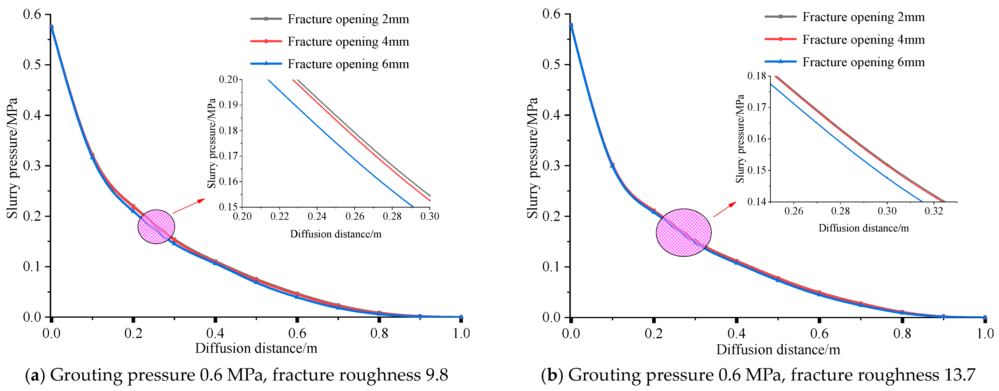
4.2. Analysis of Fracture Opening on Slurry Diffusion Law

Figure 12a,b presents the pressure variation curves of slurry with different fracture apertures as a function of diffusion distance. It can be observed from the graph that, under different fracture aperture conditions, the change in slurry pressure follows a nearly identical pattern. As the diffusion distance increases, slurry pressure decreases, displaying a non-linear distribution. When the fracture aperture is larger, the measured slurry pressure is lower, and the differences in slurry pressure at the early stage, middle stage, and final stage of the diffusion path are 0.0005 MPa, 0.0079 MPa, and 0.00085 MPa, respectively. The slurry pressure differences exhibit the same “initial increase and subsequent decrease” trend over the diffusion distance. This “initial increase and subsequent decrease” primarily pertains to the variations in the rate of slurry pressure decay. In the early stages, the slurry pressure decays more rapidly, while in the later stages, the rate of decay gradually decreases. Here, the “first increase and then reduce” mainly refers to the slurry pressure decay rate changes; the slurry pressure decay rate is larger in the early part of the slurry pressure, while the later part of the decay rate gradually decreases. This is because when the fracture aperture is larger, there is more space for slurry flow within the fracture, resulting in a more significant release of slurry pressure within the fracture and, subsequently, lower slurry pressure. Conversely, when the fracture aperture is smaller, the slurry experiences more concentrated forces within the fracture, leading to a lower degree of slurry pressure decay and, consequently, higher slurry pressure.

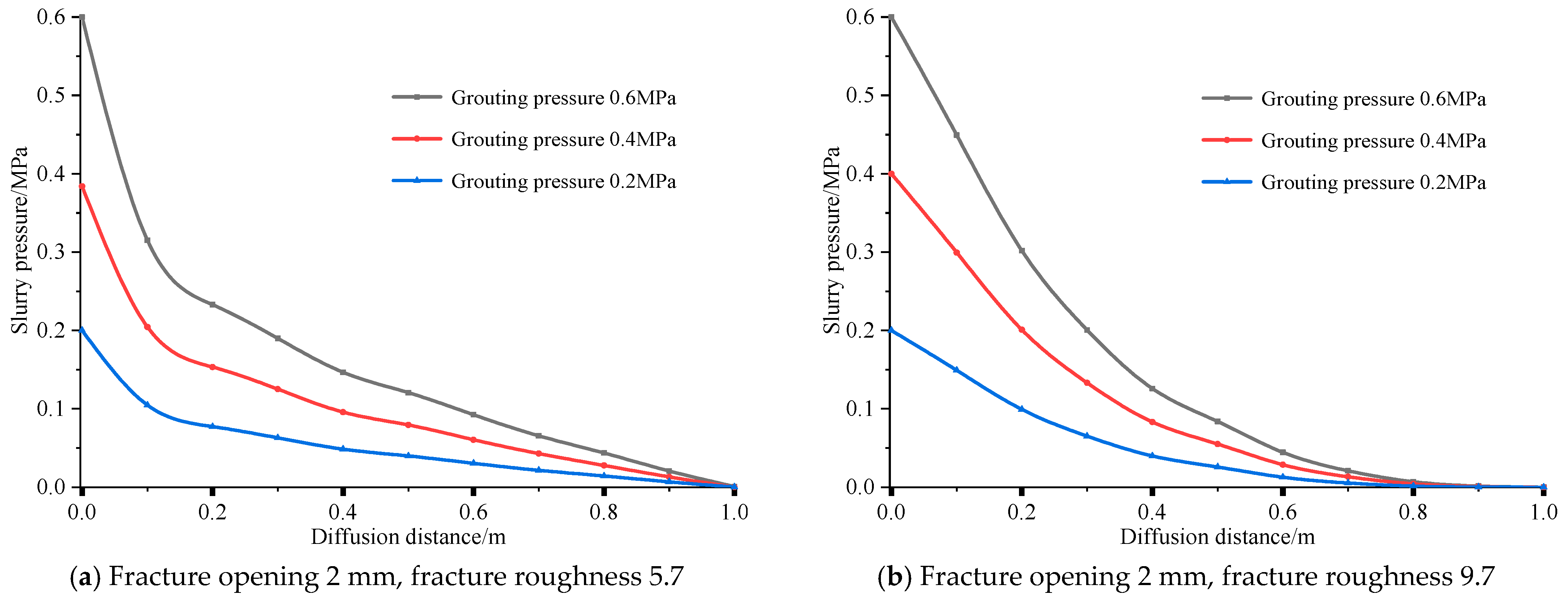
4.3. Analysis of Slurry Pressure Distribution Law by Grouting Pressure

Figure 13a,b represent the plots of slurry pressure variations with diffusion distance at different grouting pressures for fissure openness of 2 mm and fissure roughness of 5.7 and for fissure openness of 2 mm and fissure roughness of 5.7, respectively. The greater the grouting pressure, the larger the external driving force acting on the slurry, resulting in a higher slurry pressure. Overall, the evolution pattern of slurry pressure along the diffusion path is similar, showing a non-linear distribution, and the rate of slurry pressure decay exhibits an ‘initial increase and subsequent decrease’ trend along the diffusion path. This is because, as the slurry flows from the grouting pipe into the rock fractures, slurry pressure is rapidly released, leading to a faster rate of decay. However, with an increase in diffusion distance, slurry pressure decreases, resulting in smaller pressure differences per unit distance. This phenomenon is due to the fact that the pressure at the discharge orifice is equal to the external atmospheric pressure, and the greater the grouting pressure, the larger the decrease in slurry pressure. Conversely, a smaller decrease in grouting pressure leads to a smaller decrease in slurry pressure.

4.4. Comparative Analysis with Previous Studies

This study conducted a comparative analysis with the research results of Mu et al., both of which are relevant studies on the seepage characteristics of rough fractures. The main difference lies in the difference in sample dimensions, where the fractures in this experiment are three-dimensional, with dimensions of 1350 mm × 650 mm × 2 mm, whereas the fractures in Mu’s experiment are two-dimensional, with dimensions of 100 mm × 2 mm. The primary focus of this comparison is the analysis of pressure differences between different measuring points. In both cases, the results were chosen for a fracture aperture of 2 mm. The pressure difference between the measuring points in this study and the results from Mu’s study is compared in Figure 14. As shown in the figure, the pressure difference between measuring points in this study is relatively larger, showing a ‘initial decrease and subsequent stability’ trend, while in Mu’s study, the pressure difference between measuring points is relatively smaller, exhibiting a relatively stable trend. The main reason for this difference is primarily the substantial variation in sample dimensions. In cases where dimensions are smaller, pressure decay is solely related to diffusion distance, and pressure is generally linearly related to diffusion distance. However, with larger dimensions, pressure decay is not only associated with distance but also influenced by the range of pressure impact, resulting in a non-linear relationship between pressure and diffusion distance. In real grouting scenarios, the slurry diffusion range approximates a sphere, where the relationship between pressure and diffusion distance is cubic, leading to a non-linear relationship. In summary, the results of this experiment provide a good reflection of the actual pressure distribution characteristics of slurry in rough fractures.

5. Discussion of Slurry Diffusion Behavior in Rough Fractures and Analysis of Field Applications

From the results of the previous rough fracture grouting diffusion experiments, it can be observed that grouting pressure, fracture aperture, and fracture roughness have varying degrees of impact on the pressure distribution along the slurry diffusion path. Grouting pressure serves as the primary driving force enabling slurry flow within the fractures. A higher grouting pressure implies increased slurry flowability and an extended range of slurry pressure distribution. The size of the fracture aperture alters the flow space for the slurry. A larger aperture reduces the difficulty of slurry filling in the fractures, allowing slurry pressure to be more fully released and leading to decreased pressure. Greater fracture roughness, on the other hand, increases the resistance to slurry flow, resulting in a faster pressure decay rate. Therefore, for different fracture parameters in the grouting environment, the appropriate grouting techniques should be selected accordingly:
(1)
When the fracture aperture is relatively small, the roughness of the fracture will have a more pronounced effect on slurry flow. Slurry is less likely to flow within the fractures. Using a higher grouting pressure at this point can lead to local vortex phenomena due to excessive flow velocity, causing increased resistance losses along the path, which may not be conducive to slurry diffusion. Therefore, in the case of small fracture apertures, using a lower grouting pressure for construction will yield better grouting results.
(2)
When the fracture roughness is relatively high, as indicated by the earlier analysis, lower grouting pressure should be used for construction. Conversely, using a higher grouting pressure will better meet the actual grouting requirements.
(3)
When the fracture roughness is relatively high, as indicated by the earlier analysis, a lower grouting pressure should be used for construction. Conversely, using a higher grouting pressure will better meet the actual grouting requirements.
To better assess the applicability of the research findings, field applications were carried out at the Waytian Coal Mine in Guizhou. Prior to this, measurements and analysis were conducted to determine the distribution of fractures in the tunnel surrounding rock. Combining theoretical analysis and experimental results, the grouting process was optimized. A comparative analysis of tunnel deformation before and after implementing the optimized grouting process was performed. The tunnel surrounding rock deformation is shown in Figure 15a,b. From the figure, it can be observed that the use of the optimized grouting process effectively controlled the deformation of the tunnel surrounding rock, reducing it to 3 mm/day, ensuring safe and efficient coal mining operations.

6. Conclusions

In this paper, by carrying out a series of grout diffusion tests on a self-built grout diffusion simulation test system for rough fissured rock bodies, we analyzed the effects of fissure roughness, fissure openness and grouting pressure on the diffusion of slurry, and achieved the following important conclusions:
(1)
The diffusion behavior in rough fractured rock masses is primarily influenced by the combined effects of grouting pressure, fracture aperture, and fracture roughness. We developed a theoretical model of slurry diffusion considering parameters such as grouting pressure, crack aperture and crack roughness.
(2)
We independently developed a grouting test apparatus for rough fractured rock masses and conducted slurry diffusion experiments under different fracture roughness conditions, fracture apertures, and grouting pressures. The experimental results differed from the theoretical results by only 12%, indicating the high reliability of this test apparatus.
(3)
Analysis of the experimental results revealed a nonlinear positive relationship between fracture aperture and fracture roughness on slurry pressure. Grouting pressure exhibited a linear positive relationship with slurry pressure. We also conducted an analysis of the slurry diffusion behavior in rough fractured rock and provided relevant construction techniques for on-site applications.
(4)
This paper discusses the slurry diffusion behavior in rough fractured rock and, through grouting applications in the coal mine tunnel surrounding rock, optimizes the grouting process. The tunnel surrounding rock deformation was reduced to 3mm/day, ensuring safe and efficient coal mining operations.

Author Contributions

G.L.: methodology, writing—original draft, writing—review and editing. Z.L.: simulation, and experiment. F.D.: conceptualization, methodology, and funding acquisition. Z.C.: investigation, formal analysis. W.W.: investigation and software. All authors have read and agreed to the published version of the manuscript.

Funding

This research was funded by National Science Foundation of China (Grant number 52174073, 52274079), Program for the Scientific and Technological Innovation Team in Universities of Henan Province (Grant number 23IRTSTHN005), and Natural Science Foundation of Henan Province (Grant number 222300420007).

Institutional Review Board Statement

Not applicable.

Informed Consent Statement

Not applicable.

Data Availability Statement

The data used to support the findings of this study are available from the corresponding authors upon reasonable request. The data are not publicly available due to privacy.

Conflicts of Interest

The authors declare no conflict of interest.

References

  1. Jia, H.; Li, X.; Lu, L.; Ma, Q.; Zhang, P.; Zhong, Y. Study on simulation method for planar fracture grouting of expansive polymer grout based on polymerization reaction mechanism. China Civ. Eng. J. 2022, 55, 50–61. (In Chinese) [Google Scholar]
  2. Gao, M.; Zhang, R.; Xie, J.; Peng, G.; Yu, B.; Ranjith, P. Field experiments on fracture evolution and correlations between connectivity and abutment pressure under top coal caving conditions. Int. J. Rock Mech. Min. 2018, 111, 84–93. [Google Scholar] [CrossRef]
  3. Shang, Y.; Kong, D.; Pu, S.; Xiong, Y.; Li, Q.; Cheng, Z. Study on Failure Characteristics and Control Technology of Roadway Surrounding Rock under Repeated Mining in Close-Distance Coal Seam. Mathematics 2022, 10, 2166. [Google Scholar] [CrossRef]
  4. Hou, G.; Zhou, Y.; Zhao, T.; Tan, J.; Zhao, Q.; Huang, J. Excavation unloading response of cylindrical rock-like specimen with axial joints: Laboratory experiment and numerical simulation. J. Geophys. Eng. 2023, 20, 21–37. [Google Scholar] [CrossRef]
  5. He, Z.; Xie, Z.; Zhang, N.; Han, C.; Xiang, Z.; Yan, G.; Qiao, H.; Shao, C. Research on spatiotemporal evolution law of surrounding rock fractures and hierarchical collaborative control technology in high-stress soft rock roadway: A case study. Eng. Fail. Anal. 2023, 150, 107366. [Google Scholar] [CrossRef]
  6. Weng, L.; Wu, Z.; Zhang, S.; Liu, Q.; Chu, Z. Real-time characterization of the grouting diffusion process in fractured sandstone based on the low-field nuclear magnetic resonance technique. Int. J. Rock Mech. Min. 2022, 152, 105060. [Google Scholar] [CrossRef]
  7. Zhang, E.; Xu, Y.; Fei, Y.; Shen, X.; Zhao, L.; Huang, L. Influence of the dominant fracture and slurry viscosity on the slurry diffusion law in fractured aquifers. Int. J. Rock Mech. Min. 2021, 141, 104731. [Google Scholar] [CrossRef]
  8. Huang, S.; Pei, Q.; Ding, X.; Zhang, Y.; Liu, D.; He, J.; Bian, K. Grouting diffusion mechanism in an oblique crack in rock masses considering temporal and spatial variation of viscosity of fast-curing grouts. Geomech. Eng. 2020, 23, 151–163. [Google Scholar] [CrossRef]
  9. Zhai, M.; Ma, D.; Bai, H. Diffusion Mechanism of Slurry during Grouting in a Fractured Aquifer: A Case Study in Chensilou Coal Mine, China. Mathematics 2022, 10, 1345. [Google Scholar] [CrossRef]
  10. Hu, Y.; Liu, Z.; Gao, K.; Liang, D.; Cheng, S. Diffusion mechanism and sensitivity analysis of slurry while grouting in fractured aquifer with horizontal injection hole. Carbonates Evaporites 2020, 35, 49. [Google Scholar] [CrossRef]
  11. Xu, R. Flow capacity characterization of unconventional natural gas bearing rocks using digital rock physics: A comparison between advection and diffusion. J. Petrol. Sci. Eng. 2022, 215, 110624. [Google Scholar] [CrossRef]
  12. Shi, H.; Zhang, Y.; Tang, L. Physical test of fracture development in the overburden strata above the goaf and diffusion process of permeable grout slurry. Bull. Eng. Geol. Environ. 2021, 80, 4791–4802. [Google Scholar] [CrossRef]
  13. Liang, J.; Du, X.; Fang, H.; Du, M.; Shi, M.; Gao, X.; Han, Y. Numerical and experimental study of diffusion law of foamed polymer grout in fracture considering viscosity variation of slurry. Tunn. Undergr. Space Technol. 2022, 128, 104674. [Google Scholar] [CrossRef]
  14. Du, X.; Fang, H.; Wang, S.; Xue, B.; Wang, F. Experimental and practical investigation of the sealing efficiency of cement grouting in tortuous fractures with flowing water. Tunn. Undergr. Space Technol. 2021, 108, 103693. [Google Scholar] [CrossRef]
  15. Mu, W.; Li, L.; Liu, X.; Zhang, L.; Zhang, Z.; Huang, B.; Chen, Y. Diffusion-hydraulic properties of grouting geological rough fractures with power-law slurry. Geomech. Eng. 2020, 21, 357–369. [Google Scholar] [CrossRef]
  16. Mu, W.; Li, L.; Yang, T.; Yao, L.; Wang, S. Numerical calculation and multi-factor analysis of slurry diffusion in an inclined geological fracture. Hydrogeol. J. 2020, 28, 1107–1124. [Google Scholar] [CrossRef]
  17. Mohammadmoradi, P.; Taheri, S.; Bryant, S.; Kantzas, A. Solvent diffusion and dispersion in partially saturated porous media: An experimental and numerical pore-level study. Chem. Eng. Sci. 2018, 191, 300–317. [Google Scholar] [CrossRef]
  18. Sample-Lord, K.; Ahmed, M.; Malusis, M. Diffusion through soil-bentonite backfill from a constructed vertical cutoff wall. Soils Found. 2021, 61, 429–443. [Google Scholar] [CrossRef]
  19. Xuan, D.; Zhang, M.; Li, J.; Dong, Z.; Alimu, A.; Xu, J. Experimental Study on the Diffusion Radius of Modified Slurry Used in Longwall Overburden Isolated Grouting. Geofluids 2023, 2023, 7195779. [Google Scholar] [CrossRef]
  20. Zhong, Z.; Li, J.; Bie, C. Theoretical Approach to Predicting the Diffusion Radius of Fracture Grouting in Soil-Rock Mixtures. Appl. Sci. 2023, 13, 4730. [Google Scholar] [CrossRef]
  21. Bai, X.; Zhang, Z.; Shi, H.; Luo, Z.; Li, T. Identification of Subsurface Mesoscale Crack in Full Ceramic Ball Bearings Based on Strain Energy Theory. Appl. Sci. 2023, 13, 7783. [Google Scholar] [CrossRef]
  22. Li, S.; Pan, D.; Xu, Z.; Lin, P.; Zhang, Y. Numerical simulation of dynamic water grouting using quick-setting slurry in rock fracture: The Sequential Diffusion and Solidification (SDS) method. Comput. Geotech. 2020, 122, 103497. [Google Scholar] [CrossRef]
  23. Li, Z.; Zhu, Z.; Zhao, Y.; Zeng, C.; Zhang, P. Experimental Investigation on the Diffusion Law of Polymer Slurry Grouted in Sand. Polymers 2022, 14, 3635. [Google Scholar] [CrossRef] [PubMed]
  24. Jin, L.; Sui, W. Experimental investigation on chemical grouting in rough 2D fracture network with flowing water. Bull. Eng. Geol. Environ. 2021, 80, 8519–8533. [Google Scholar] [CrossRef]
  25. Wang, C.; Diao, Y.; Guo, C.; Li, P.; Du, X.; Pan, Y. Two-stage column–hemispherical penetration diffusion model considering porosity tortuosity and time-dependent viscosity behavior. Acta Geotech. 2023, 18, 2661–2680. [Google Scholar] [CrossRef]
  26. Ge, H.; Yang, L.; Shen, Y.; Ren, K.; Meng, F.; Ji, W.; Wu, S. Experimental investigation of shale imbibition capacity and the factors influencing loss of hydraulic fracturing fluids. Petrol. Sci. 2015, 12, 636–650. [Google Scholar] [CrossRef]
  27. Guo, Y.; Zhang, Q.; Xiao, F.; Liu, R.; Wang, Z.; Liu, Y. Grouting rock fractures under condition of flowing water. Carbonate. Evaporite. 2020, 35, 96. [Google Scholar] [CrossRef]
  28. Pan, W.; Liang, S.; Liu, S.; Zhao, Z.; Zha, D. Numerical Simulation of Diffusion Regularity and Parameter Optimization of Shaft Grouting Slurry. Processes 2022, 10, 803. [Google Scholar] [CrossRef]
  29. Liu, Y.; Wu, Z.; Weng, L.; Wu, L.; Xu, X.; Liu, Q. Experimental study on the Grouting Diffusion Process in Fractured Sandstone with Flowing Water Based on the Low-Field Nuclear Magnetic Resonance Technique. Rock Mech. Rock Eng. 2023, 56, 7509–7533. [Google Scholar] [CrossRef]
  30. Zhou, Y.; Liu, B.; Wu, Z.; Jiang, Y.; Liu, Q.; Weng, L.; Li, M. Experimental Investigation on the Grouting Diffusion Characteristics and Relative Filling Degree of Chemical Slurry in Fractured Porous Sandstone. Rock Mech. Rock Eng. 2023, 56, 7819–7837. [Google Scholar] [CrossRef]
  31. Mu, W.; Li, L.; Yang, T.; Yu, G.; Han, Y. Numerical investigation on a grouting mechanism with slurry-rock coupling and shear displacement in a single rough fracture. Bull. Eng. Geol. Environ. 2019, 78, 6159–6177. [Google Scholar] [CrossRef]
  32. Jia, H.; Wang, F.; Li, X.; Gui, Y.; Zhong, Y.; Zhang, B. Experimental and Numerical Studies of Self-Expansible Polyurethane Slurry Diffusion Behavior in a Fracture Considering the Slurry Temperature. Sustainability 2023, 15, 8563. [Google Scholar] [CrossRef]
  33. Ruan, W. Spreading model of grouting in rock mass fractures based on timed-dependent behavior of viscosity of cement-based grouts. Chin. J. Rock Mech. Eng. 2005, 15, 2709–2714. (In Chinses) [Google Scholar]
  34. Liu, J.; Zhang, Z.; Han, Y.; Wu, X. Backfilled grouting diffusion law and model of pressure on segments of shield tunnel considering viscosity variation of cement grout. Rock Soil Mech. 2015, 36, 361–368. (In Chinese) [Google Scholar]
  35. Zhang, Q.; Zhang, L.; Zhang, X.; Liu, R.; Zhu, M.; Zheng, D. Grouting diffusion in a horizontal crack considering temporal and spatial variation of viscosity. Chin. J. Rock Mech. Eng. 2015, 34, 1198–1210. (In Chinese) [Google Scholar]
  36. He, G. Study on the Modified Equation of Single Fracture Seepage with Roughness Angle; Tsinghua University: Beijing, China, 2014; p. 43. (In Chinese) [Google Scholar]
  37. Wang, X. Mechanism of Grouting Diffusion and Reinforcement of Rock Fracture Based on the Bleeding Effect of Cement Slurry; Shandong University: Jinan, China, 2021; p. 93. (In Chinese) [Google Scholar]
Figure 1. Force analysis diagram of slurry microelement.
Applsci 14 00047 g001
Figure 2. Slurry flow rate distribution.
Applsci 14 00047 g002
Figure 3. Test schematic diagram.
Applsci 14 00047 g003
Figure 4. Rock grouting system.
Applsci 14 00047 g004
Figure 5. Rough cleavage plate.
Applsci 14 00047 g005
Figure 6. Rough fracture seepage system.
Applsci 14 00047 g006
Figure 7. Layout of monitoring equipment.
Applsci 14 00047 g007
Figure 8. Physical diagram of rough fissure grouting system.
Applsci 14 00047 g008
Figure 9. Plot of slurry pressure over time at each monitoring point.
Applsci 14 00047 g009
Figure 10. Comparison of slurry pressure test result values and theoretical calculation value Curve diagram.
Applsci 14 00047 g010
Figure 11. Plot of slurry pressure variations with diffusion distance for different fracture roughnesses.
Applsci 14 00047 g011
Figure 12. Variations in slurry pressure with diffusion distance for different fracture openings.
Applsci 14 00047 g012
Figure 13. Variations in slurry pressure with diffusion distance under different grouting pressures.
Applsci 14 00047 g013
Figure 14. Comparison curve of pressure differences between different measurement points.
Applsci 14 00047 g014
Figure 15. Change curve of displacement monitoring results.
Applsci 14 00047 g015
Table 1. Parameters of grouting test.
Fracture Opening (mm)Fracture RoughnessState
0.2 MPa0.4 MPa0.6 MPa
25.7
9.8
13.6
17.3
45.7
9.8
13.6
17.3
65.7
9.8
13.6
17.3
(Note: “√” means conducted under this condition, used to verify the reliability of the device).
Disclaimer/Publisher’s Note: The statements, opinions and data contained in all publications are solely those of the individual author(s) and contributor(s) and not of MDPI and/or the editor(s). MDPI and/or the editor(s) disclaim responsibility for any injury to people or property resulting from any ideas, methods, instructions or products referred to in the content.

