Article

Microgravity Decoupling in Torsion Pendulum for Enhanced Micro-Newton Thrust Measurement

1
School of Physical Sciences, University of Chinese Academy of Sciences (UCAS), Beijing 100049, China
2
Key Laboratory of Vacuum Physics, University of Chinese Academy of Sciences, Beijing 100049, China
3
Gravitational Cosmic Taiji Laboratory (Beijing/Hangzhou), University of Chinese Academy of Sciences, Beijing 100049, China
4
School of Fundamental Physics and Mathematical Sciences, Hangzhou Institute for Advanced Study, University of Chinese Academy of Sciences, Hangzhou 310024, China
5
National Space Science Center, Chinese Academy of Sciences, Beijing 100190, China
*
Author to whom correspondence should be addressed.
Appl. Sci. 2024, 14(1), 91; https://doi.org/10.3390/app14010091
Submission received: 16 November 2023 / Revised: 10 December 2023 / Accepted: 19 December 2023 / Published: 21 December 2023

Abstract

:
To enhance the accuracy of micro-Newton thrust measurements via a torsion pendulum, addressing microgravity coupling effects caused by platform tilt and pendulum mass eccentricity is crucial. This study focuses on analyzing and minimizing these effects by alleviating reference surface tilt and calibrating the center of mass during thrust measurements. The study introduced analysis techniques and compensation measures. It first examined the impact of reference tilt and center of mass eccentricity on the stiffness and compliance of the torsion pendulum by reconstructing its dynamic model. Simscape Multibody was initially employed for numerical analysis to assess the dynamic coupling effects of the tilted pendulum. The results showed the influence of reference tilt on the stiffness and compliance of the torsion pendulum through simulation. An inverted pendulum was developed to amplify the platform’s tilt angle for microgravity drag-free control. Center of mass calibration can identify the gravity coupling caused by the center of mass position. Based on the displacement signal from the capacitive sensor located at the end of the inverted pendulum, which represents the platform’s tilt angle, the pendulum’s vibration at 0.1 mHz was reduced from 5.7 μ m/Hz1/2 to 0.28 μ m/Hz1/2 by adjusting the voltage of piezoelectric actuator. Finally, a new two-stage torsion pendulum structure was proposed to decouple the tilt coupling buried in both pitch and roll angle. The study utilized theoretical models, numerical analysis, and experimental testing to validate the analysis methods and compensation measures for microgravity coupling effects in torsion pendulums. This led to a reduction in low-frequency noise caused by ground vibrations and thermal strains, ultimately improving the micro-Newton thrust measurement accuracy of the torsion pendulum through the platform’s drag-free control.

1. Introduction

The demand for precise satellite pointing accuracy, or drag-free control, is increasing due to scientific missions like space gravitational wave detection [1] and Earth gravity field measurement [2]. Micro-thrusters play a crucial role as actuators for drag-free control [3,4], making it essential to measure their thrust range, resolution, response time, and noise characteristics accurately [5]. Ground calibration of micro-thrusters often involves using a torsion pendulum to achieve stable measurements. However, achieving stability at low frequencies below 0.1 μ N/Hz1/2 (1 mHz) remains a significant challenge due to factors like ground vibrations, temperature fluctuations, and air disturbances [6,7]. Traditional ground calibration of propulsion systems involves using precision thrust stands equipped with high-precision sensors and data acquisition systems to capture and analyze thrust output [8]. Research in this area covers dynamics modeling, standard force generation, gas supply and power supply design, low-frequency noise decoupling, and data processing algorithms [9,10,11]. Most research on the torsional pendulum assumes that stiffness remains constant after calibration, which may be sufficient for short-term measurements or cases where heat-induced table deformation can be disregarded. However, for frequencies below 1mHz, the discussion about the residual gravity coupling in existing weak force measurement devices is crucial. For the reference tilt, we will introduce a disturbance in the balance of the torsion pendulum, resulting in an additional source of systematic error and causing variations in the torsional stiffness and compliance of the pendulum. This ultimately impacts its motion equation and measurement accuracy.
When reviewing the impact of reference tilt on measurement, the following study provides a relevant analysis. Ziemer et al. [12] examined the impact of reference tilt on torsion pendulum measurements and determined that it can change both the strength and direction of the gravity-induced torque, thus impacting the neutral position and stability of the torsion pendulum. To minimize this effect, it is advisable to position the center of mass near the axis of rotation and reduce external vibration. Manuel et al. [6] proposed a torsional balance to characterize micro-Newton thrusters. The arm rotates around the axis defined by two aligned flexural pivots attached to both the arm and the frame, whose inclination is adjusted with two stepper motors, making it possible to test thrust noise below 0.1 μ N/Hz1/2 above 7 mHz. Trezzolani et al. [13] developed a counterbalanced pendulum thrust stand specifically designed for electric propulsion systems. This innovative counterbalanced-type pendulum design allows for easy adjustment of instrument sensitivity without needing to alter the overall size of the pendulum. Still, it is essential to implement an algorithm that can effectively correct any thermal drifts that may occur during thruster operation. Gilpin et al. [14] believe that tilting causes the torsion pendulum to lose balance and changes its sensitivity, reducing its ability to respond to small torques; in addition, tilting introduces additional vibrations that affect the stability and accuracy of the torsional pendulum. Zhang et al. [15] developed and validated a micro-Newton torsional thrust balance for an ionic liquid electrospray thruster. To mitigate the impact of gravitational forces on measurement outcomes, the system incorporates a two-dimensional adjustable counterweight mechanism to achieve equilibrium across the entire arm and ensure its center of mass is in close proximity to the pivot axis. It is evident that the resolution of the frame for long-term micro-Newton-level thrust measurement of heavy thrusters depends on the stability of the reference and is influenced by changes in the frame’s recovery stiffness, center of mass offset, and environmental temperature, based on the thrust-to-weight ratio of the load. Still, most studies have not yet systematically analyzed the impact of reference tilt on the torsion pendulum or conducted corresponding decoupling experiments. This paper, therefore, explores the microgravity coupling effect caused by reference tilt and centroid shift during micro-thrust measurement, along with the related analysis and compensation methods.
The article is structured as follows. First, it discusses the reconstruction of the dynamic model of the torsional pendulum, focusing on the reference tilt and centroid shift. Next, it analyzes the impact of various factors on the stiffness of the torsional pendulum’s resolution through dynamics simulation using Simscape Multibody [16]. Following this, the stiffness and compliance functions are fitted. A method is then proposed to detect the reference tilt based on the inverted pendulum’s position, and a technique is suggested for calibrating the center of mass through thrust and tilt angle modulation. The reference leveling is controlled by a piezoelectric actuator, and the tilt drift is confirmed through experimentation. To address the potential issue of reference leveling, a two-stage torsion pendulum in series is suggested to achieve the separation of gravity and thrust. In summary, this paper systematically examines the microgravity coupling problem of the torsion pendulum through theoretical analysis, numerical simulation, and experimental verification. It also introduces compensation methods for reference leveling and centroid calibration, which can be used as a reference for measuring micro thrust based on the torsion pendulum.

2. Device and Method

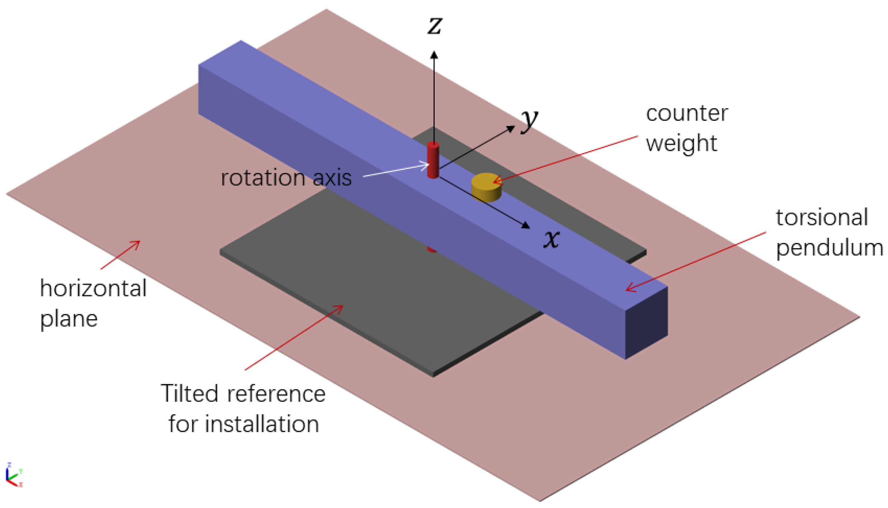
2.1. Torsion Pendulum and Its Dynamics

The torsion pendulum rotates in a horizontal plane perpendicular to the axis, supported by suspended threads or flexural pivots that provide the restoring torque. It is commonly used to measure micro thrust or micro impulse through angular deflection in the horizontal direction, due to the balance of gravity of the pendulum frame. In theory, the equation of motion of a torsional pendulum can be expressed as:
J θ + λ θ + K θ = τ t ,
where J is the moment of inertia of the torsion pendulum, θ is the angular displacement of the torsion pendulum, λ is the damping coefficient of the torsion pendulum, K is the torsional stiffness of the torsion pendulum, and τ ( t ) is the external force acting on the torsion pendulum.
In the actual measurement, the displacement sensor is usually used to measure the displacement of the endpoint of the torsion pendulum, and then the electrostatic force or electromagnetic force is used for calibration. When the torsional pendulum is statically balanced and coupled without gravity, the relationship is satisfied:
τ t = F L = K 0 θ ,
where F is the thrust to be measured, L is the torque arm, and K 0 is the torsional stiffness of the pivot. Generally, when the thrust measurement period is short, the relationship between and is constant. However, when the measurement period is long, because of the thermal strain of the structure [17], the installation base of the torsion pendulum is no longer fixed, the tilt caused by thermal expansion and cold contraction, the center of mass of the pendulum frame deviates from the rotating axis, so that the quasi-static balance relationship of the torsion pendulum becomes:
F L + M g s i n α l c m = K 0 θ ,
where M represents the mass of the pendulum frame, g denotes the acceleration due to gravity, l c m signifies the distance between the center of mass of the pendulum frame and the axis of rotation, and α represents the angle between the axis of rotation and the direction of gravity, as well as the angle of tilt of the horizontal plane. In the given equation, the force being measured is balanced by the gravitational force acting on the pendulum frame and the restorative force of the rotating shaft. Additionally, the reference tilt and the offset of the center of gravity contribute to the noise in the force.
For the convenience of research, as shown in Figure 1 and Figure 2, the length direction of the pendulum frame is defined as x, and the vertical direction of the pendulum frame is defined as y. The reference inclination α can be decomposed into rotations around x and y, corresponding to the roll and pitch of the pendulum frame, respectively. Similarly, l c m can be decomposed into the horizontal offsets along the x and y directions, denoted as l c m , x and l c m , y . In this paper, the inclination in the horizontal plane can be decoupled into roll or pitch, which correspond to the combinations of ϕ x and l c m , y , or ϕ y and l c m , x , respectively. Although it is not possible to completely decouple pitch and roll when discussing the sensitivity to inclination, it is still possible to discuss a single-dimensional coupled model and remove the influence of inclination on force measurement results.

2.2. Modeling of Gravity Coupling

According to Equation (3), the torque stiffness of the torsional pendulum under the action of thrust F can be obtained as:
K = F L θ = K 0 M g s i n α l c m θ ,
where, the nominal stiffness K includes the flexural pivot’s elastic stiffness K 0 and the gravity stiffness M g s i n ( α ) l c m θ . The former is determined by the pivot material and is independent of the applied force within a certain range. The latter is not only connected to the mass of the pendulum frame, the gravitational acceleration, the reference inclination, and the centroid offset, but also to the deflection angle θ of the torsional pendulum caused by the measured thrust. However, analyzing the variation of stiffness with the inclination of the mounting reference is not straightforward due to the fact that the inclination α also affects the angular deformation of the torsional pendulum.
The compliance is the reciprocal of stiffness and represents the (angular) displacement generated by a unit force (torque) in the system [18]. In the previous discussion, for a specific thrust F, under the combined action of pivot elasticity and pendulum frame gravity, the torque compliance of the torsional pendulum system can be expressed as:
S = 1 K 0 + M g s i n ( α ) l c m F L .
In this equation, there are no other variables related to α . Under the small angle approximation, the linear relationship between compliance and inclination becomes simpler. During this process, the stiffness of the torsional pendulum varies according to K = 1 S , and Equation (4) can be rewritten as:
K = 1 1 + M g s i n ( α ) l c m F L K 0 .
The physical interpretation of this equation is more intricate. Ideally, K = K 0 when M g s i n ( α ) l c m = 0 . However, we need to consider at least three cases when M g s i n ( α ) l c m 0 .
  • M g s i n ( α ) l c m F L > 0 :
    In this case, 0 < K < K 0 and the torque from the thrust and gravity act in the same direction. For example, when a force is applied to the torsional pendulum, although it experiences a restoring force from the pivot, the stiffness gradually decreases as the gravitational component introduced by the inclination increases.
  • 1 < M g s i n ( α ) l c m F L < 0 :
    In this case, the torque from the thrust and gravity act in opposite directions, but their combined torque is in the same direction as the thrust torque. The elastic torque and the gravity torque also act in the same direction, which means that the torsional pendulum and the gravity pendulum are superimposed. In this scenario, K > K 0 . Particularly, when M g s i n ( α ) l c m F L 1 , the stiffness increases sharply.
  • M g s i n ( α ) l c m F L < 1 :
    In this case, the torque from the thrust and gravity act in opposite directions, but their combined torque is in the same direction as the gravity torque. The elastic torque and the thrust torque also act in the same direction, resulting in a reverse stiffness of the system, K < 0 . This is beyond the scope of this discussion.
It can be seen that under the condition of reference tilt, with the influence of centroid deviation, the stiffness change law of the torsion pendulum is not intuitive. Therefore, this paper will first use a Simscape visual modeling tool for semi-physical simulation and error analysis, to fit the numerical effects of the reference tilt and centroid shift. In particular, by simulating the thrust and displacement time series of the torsion pendulum in the process of gravity coupling, the thrust-displacement transfer function of the system is identified, and the variation law of its compliance and displacement with the center of gravity and tilt is obtained.

3. Numerical Analysis

3.1. Multibody Simulation

In Simscape Multibody, a multibody system of a torsional pendulum is modeled using modules representing objects, joints, constraints, force elements, and sensors, making it possible to build a dynamic model of the entire structure and solve its equations of motion. Based on the finite element modeling method, the reference inclination, centroid offset, and other parameter attributes are changed by MATLAB scanning, different thrust is excited in the model, and the simulation model of the given parameters is run to collect the discrete thrust and displacement time series data. Then, the system identification method, such as the least square method, is used to obtain the thrust—displacement transfer function, and the value of its transfer function at the frequency of 0 is viewed. The study was conducted on different stiffness values of 0.2 Nm / rad and 0.02 Nm / rad , and the results are shown in Figure 3 and Figure 4. First, regardless of the gravity coupling and resolution force magnitude, the eigenfrequency peaks corresponding to different stiffness values in the amplitude spectrum of the thrust-displacement transfer function are different. Under the condition of constant mass or moment of inertia of the pendulum frame, the low-stiffness torsional pendulum has a higher overall compliance level near 0 Hz . Second, for the case of a smaller resolution force of F = 0.1 μ N , the gravity coupling caused by the same angle of inclination is more uncertain, resulting in a more discrete compliance obtained through position calibration. This is more pronounced in the case of low stiffness. From the perspective of the compliance variation caused by the inclination of the pendulum frame, lower resolution force and lower stiffness both contribute to thrust noise, and determining the threshold of reference inclination required for different resolution force levels becomes more critical.
To this end, simulation data of a torsional pendulum with a nominal stiffness of 0.2 Nm / rad and a resolution force of 1 μ N square wave thrust, with the same center of mass offset, were used to fit the stiffness and compliance values for different pitch angles ranging from 20 μ rad to 20 μ rad . These angles are chosen to cover the platform’s tilt range during thermal expansion and contraction over a long period of time. For instance, using an iron quadruped platform as support, when the temperature fluctuates within ±2 °C, which is within the predictable range, the material’s thermal expansion coefficient is 12.2 × 10 6 /K. When the fluctuation on a 1-meter-long plate exceeds ±25 μ m, the inclination angle approaches ±20 μ rad. Moreover, depending on whether the torsion pendulum remains stable as gravitational coupling increases, there will be convergence due to changes in stiffness or flexibility within this range. Despite an obvious divergence of ±20 μ rad mentioned in the paper and considering a resolution of 0.1 μ N, overall calculations remain valid.
As shown in Figure 5, the stiffness varies with the reference inclination in a binomial exponential fitting relationship, while as shown in Figure 6, the compliance has a linear relationship with the corresponding inclination. It can be seen that the stiffness variation curve caused by inclination is neither symmetric nor linear, and the binomial exponential form represents the process of the elastic stiffness of the torsional pendulum evolving into gravitational stiffness. For a specific resolution force, the upper and lower limits of the corresponding pitch angles can be inferred based on the stiffness variation represented by interpolated exponential terms. It is important to note that both the stiffness and compliance fitting ranges have a certain range of angles. Empirically, the gravity coupling torque at the maximum inclination angle should be less than 1/4 of the measured torque to avoid non-linear changes in stiffness or compliance.

3.2. Tilt Angle Monitoring

In the process of measuring micro thrust using a torsional pendulum, it is sensitive to the inclination of the platform reference. The sensitivity of the torque of the measured thrust to the platform tilt angle is on the order of 0.01 μ N · m / μ rad or even lower. Conventional commercial tilt sensors have limited detection accuracy. For example, MEMS sensors can only resolve the smallest tilt angle of 0.001° (approximately 17 μ rad ), which is insufficient for detecting and compensating for small tilts. Therefore, it is necessary to design a mechanism that amplifies the reference tilt angle, which can not only resolve the weak changes in thrust but also provide a good reference for the platform tilt and the direction of the gravitational field. Figure 7 shows a reference tilt amplification mechanism designed based on the inverted pendulum principle [19,20].
For the inclined inverted pendulum, considering only the balance between gravity and elasticity, the equation can be written as:
m g L c m sin θ + φ = k θ .
where m is the mass of the inverted pendulum, L c m is the length of the center of mass position arm, θ is the deviation angle of the inverted pendulum, φ is the inclination angle of the reference surface, and k is the torque stiffness coefficient. This equation describes the balanced relationship between the gravity, deviation angle, and reference tilt angle of the inverted pendulum. In the small angle approximation, sin ( θ + φ ) θ + φ , and the balance equation can be simplified as:
m g L c m θ + φ k θ .
According to the above equation, the ratio between the deformation angle θ and the reference tilt angle φ of the inverted pendulum can be expressed as:
N = θ φ = 1 k m g L c m .
When the gravity stiffness m g L c m of the inverted pendulum is close to its elastic deformation stiffness k, N will rapidly increase. This means that the relationship between the deviation angle of the inverted pendulum and the normal tilt angle of the reference surface becomes more significant. This amplifies the detection of small tilt angles, but if the ratio N becomes too large, it will lead to a rapid increase in the structural instability of the inverted pendulum.
In practical applications, the ratio N is usually controlled within a reasonable range, so as to amplify small tilt angles while maintaining the stability of the structure. Therefore, it is necessary to choose appropriate gravity stiffness and elastic deformation stiffness based on specific application requirements and structural parameters, in order to balance the relationship between amplification detection and structural stability. In theory, the gravity stiffness of a pendulum depends on the weight of the mass center ( m g ) and its distance from the axis ( L c m ), while the elastic stiffness of a flexural pivot is determined by its dimensions and material. However, in practice, these values are simulated by designers or calibrated through experiments, such as adjusting the counterweight to modify the period of the inverted pendulum, in order to achieve the desired reference tilt amplification ratio. For example, the amplification factor N is approximately 10 when k = 0.1 Nm / rad and m g L c m = 0.09 Nm / rad . It is worth noting that, after the weight increases to a certain extent, the gravity stiffness of the inverted pendulum exceeds the elastic stiffness of the pivot, and the small angle approximation condition after gravity acceleration coupling is no longer satisfied. The amplification angle and the total stiffness will increase rapidly according to an exponential law.
Because m g L c m sin ( θ + φ ) k θ is a transcendental equation, it is difficult to solve analytically. Numerical simulation analysis can be used to obtain suitable design parameters. For this purpose, Simscape Multibody can also be used for simulation to model the structure, dimensions, and weight of the inverted pendulum on a 1:1 scale. Here, assuming a reference tilt of 1 mrad for the inverted pendulum, different masses of counterweights are used, and the stabilized angle is observed. The data are then fitted using a binomial exponential function, as shown in Figure 8. By considering the maximum deflection angle that the bearing can withstand, an appropriate mass of counterweight (e.g., 180–190 g) can be found to achieve an amplification factor of around 10.

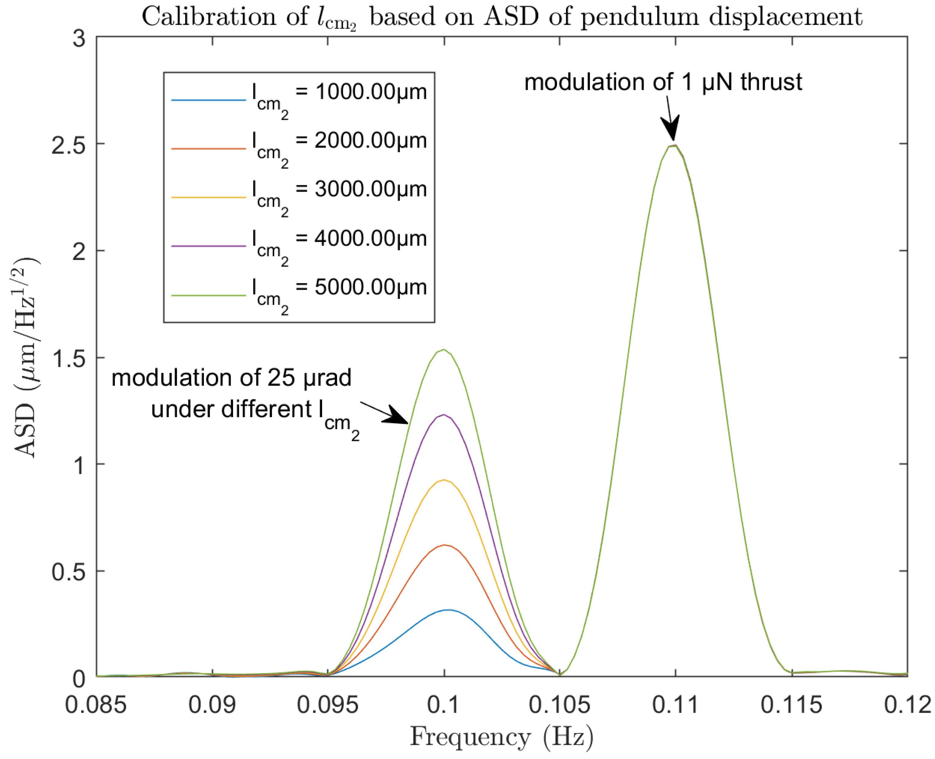
3.3. Center of Mass Calibration

In the previous two sections, the influence of the reference tilt on the stiffness of the torsional pendulum was modeled and analyzed using Simscape Multibody. Feasible methods for amplifying the reference tilt based on counterweights for the inverted pendulum were also provided. However, it is difficult to completely eliminate the effects of microgravity drag by leveling the reference under the condition of default center of mass offset. Therefore, by modulating the tilt angle of the reference surface and calibrating the relative position of the center of mass of the torsional pendulum, the microgravity coupling and thrust noise of the pendulum frame can be monitored and compensated.
To calculate the center of mass offset of the pendulum frame during torsion, a model shown in Figure 9 (front view) and Figure 10 (top view) can be used to represent the mass distribution of the pendulum frame:
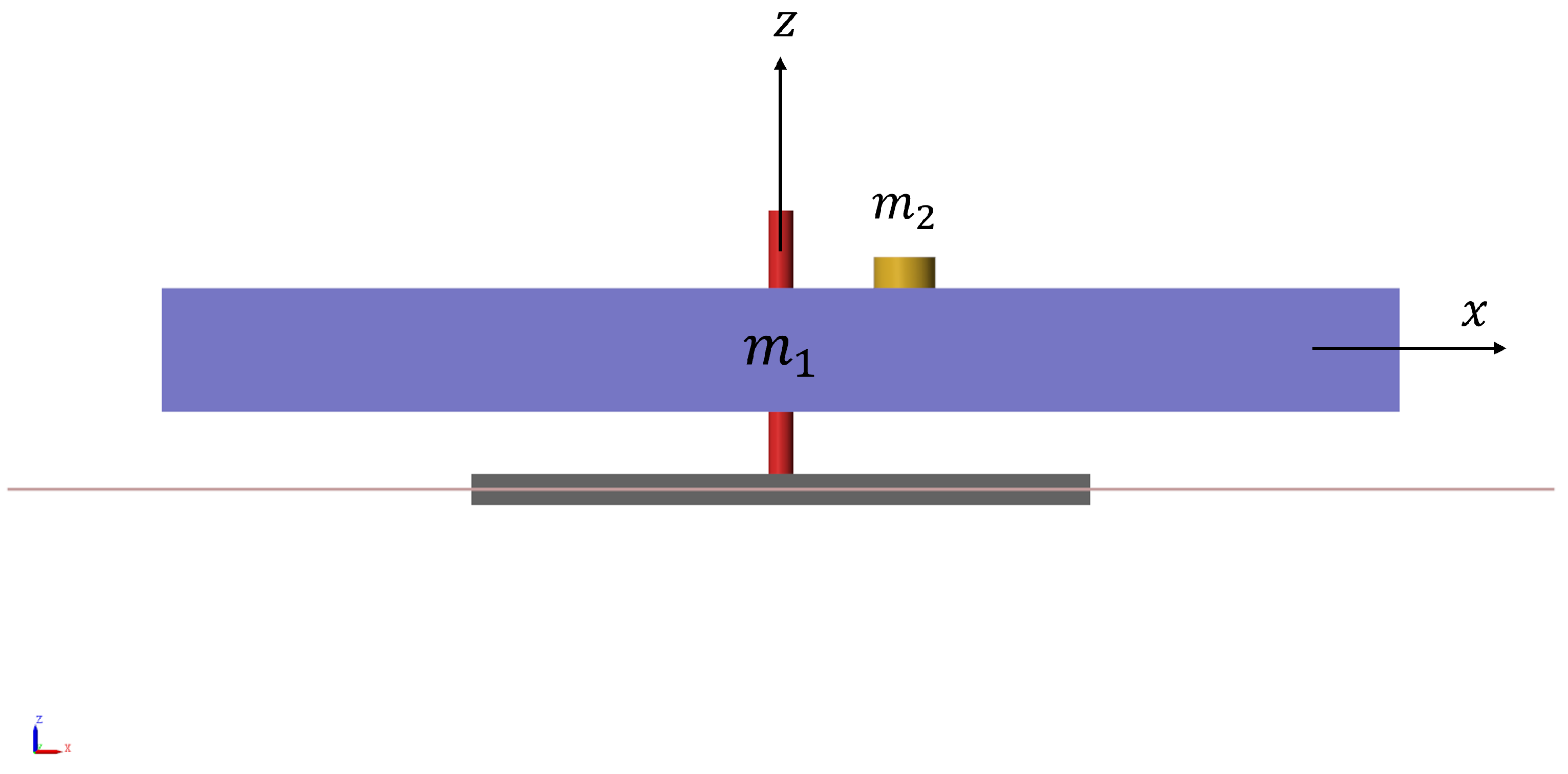
  • Divide the mass of the pendulum frame into symmetric parts that are balanced on the left and right sides, and an unbalanced part (counterweight block). The sum of the mass of the balanced parts on both sides is m 1 , and the mass of the unbalanced counterweight block is m 2 .
  • Define the center of mass position of m 1 as the coordinate origin (i.e., the pivot point), and the horizontal distance between the center of mass of the counterweight m 2 and the pivot point as l c m 2 . At this point, the overall mass of the pendulum frame is M = m 1 + m 2 , and the center of mass position caused by the unbalanced counterweight is:
    l c m = m 2 m 1 + m 2 · l c m 2 .
    Here, the overall center of mass offset of the pendulum frame is equivalent to the tilting moment caused by the counterweight alone.
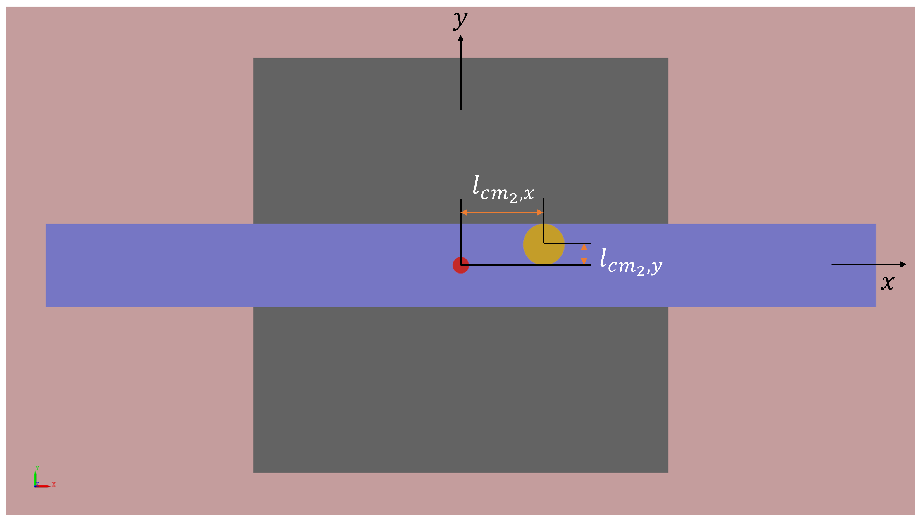
  • In particular, the horizontal distance between the center of mass of the counterweight block and the pivot point on the vertical plane in the direction perpendicular to the pendulum arm is l c m 2 , y . The center of mass offset caused by the counterweight block and the coupling due to the reference pitch tilt is:
    M g sin ϕ y · l c m , y = m 2 g sin ϕ y · l c m 2 , y .
  • Similarly, the horizontal distance between the center of mass of the counterweight block and the pivot point on the horizontal plane in the direction of the pendulum arm is l c m 2 , x . The center of mass offset caused by the counterweight block and the coupling due to the reference roll tilt is:
    M g sin ϕ x · l c m , x = m 2 g sin ϕ x · l c m 2 , x .
Using the models described above, it is possible to flexibly describe the center of mass offset of the pendulum frame and calculate the positions and weights of different structures, such as thrusters and counterweight blocks, which will help analyze and compensate for the coupling of microgravity in the torsional pendulum. Additionally, based on existing research, it is known that the effects of reference roll and pitch can be decoupled. Therefore, in the following analysis, only the tilt angle α in the pitch direction will be considered, and the resulting changes in influence will be understood.
Similarly, using the Simscape Multibody modeling, the coupling variations of different center of mass positions in the pendulum frame will be compared based on pitch and thrust. For example, by periodically adjusting the pitch angle of the platform at 25 μ rad and 0.1 Hz, and simultaneously applying synchronized thrust on the pendulum frame at 1 μ N and 0.11 Hz, the displacement amplitude spectral density (ASD) changes of the torsional pendulum will be observed when the counterweight is positioned at distances of 1 mm, 2 mm, 3 mm, 4 mm, and 5 mm from the axis. As shown in Figure 11, as the center of mass offset of the pendulum frame increases due to the increasing distance of the counterweight, the peak at 0.1 Hz caused by the platform tilt modulation gradually increases, while the peak at 0.11 Hz caused by the thrust modulation remains constant. It can be seen that by modulating the thrust and platform tilt at different frequencies and with equal amplitudes, the ASD peak value of the torsional pendulum position and the degree of offset in calibrating the center of mass can be determined.

4. Results and Discussion

4.1. The Baseline Leveling Experiment

The torsional pendulum’s microgravity coupling experiment described in this article is currently being conducted in an air environment and has not yet been combined with the operation of a thruster. During the preliminary design of the decoupling experiment, to control variables and reduce the coupling among multiple physical fields, we are currently mainly considering the long-term tilt effects from the installation reference. In fact, the torsional pendulum’s microgravity decoupling will eventually be applied in a vacuum chamber and will be subject to multiple disturbances from pumps, coolers, etc. The following are some real measurement results of the benchmark leveling experiment.

4.1.1. Tilt Detection

The first step in eliminating microgravity coupling in torsional oscillations is detection. In this paper, an inverted pendulum is used to test the tilt angle of the torsional reference plane. As shown in Figure 12, after shielding airflow disturbances, using a stationary optical platform, and recording for a long time, a capacitive displacement sensor detects the periodic sawtooth wave variations at the end of the inverted pendulum, with an amplitude of 10–15 nm . When converted with a 5 cm arm length and a 1× tilt amplification factor, this corresponds to at least 0.2 0.3 μ rad of tilt variation in the reference. However, no effective thrust was applied to the torsional system during this period.
It is observed that the displacement variation occurs with a period of several hundred seconds, which is caused by the periodic operation of the water cooling system used for the vacuum pump. Due to temperature changes affecting the tilt angle of the platform reference, the inverted pendulum detects long-term drift under triangular wave modulation.

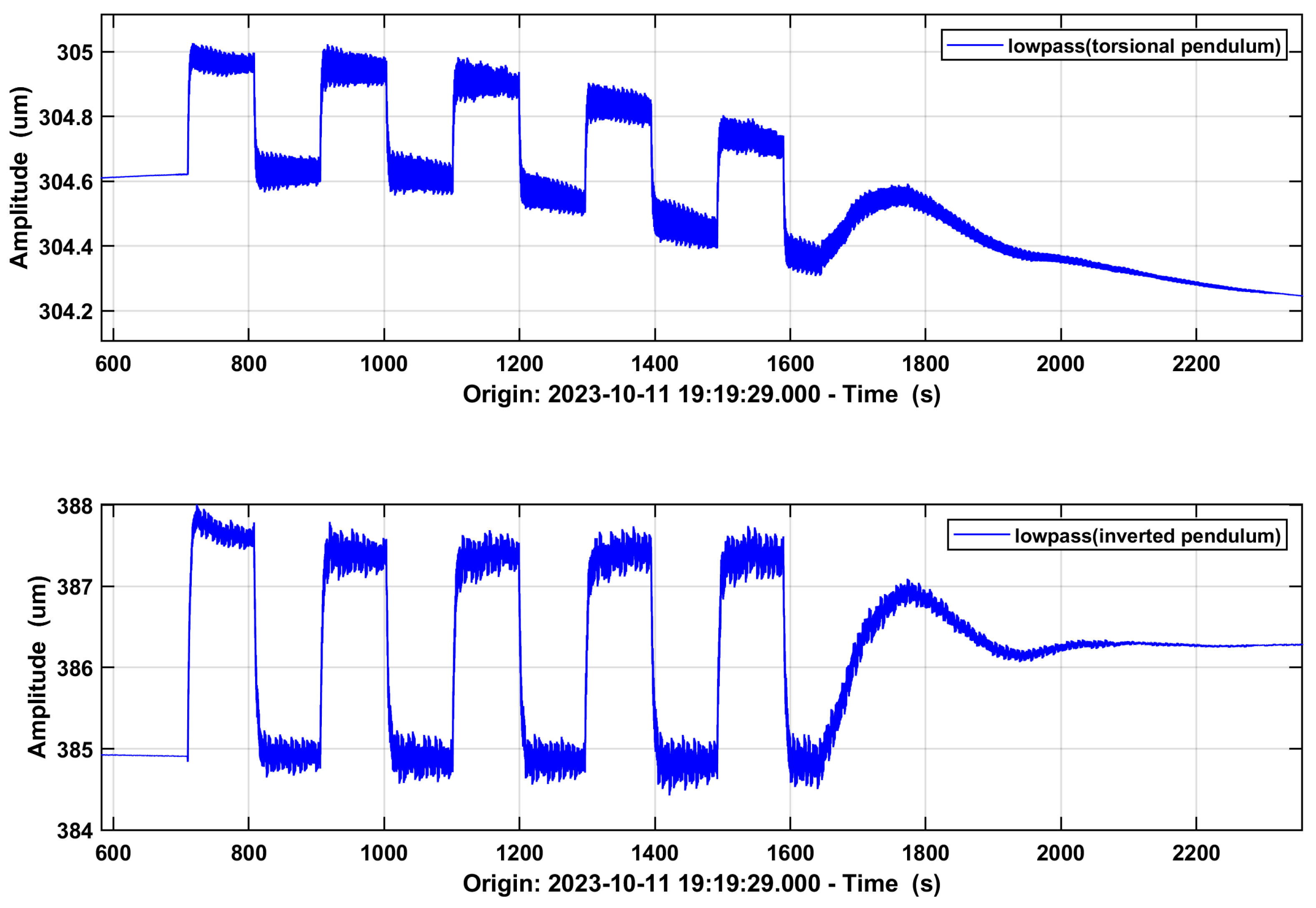
4.1.2. Tilt Modulation

The previous experiments demonstrated the feasibility of monitoring the tilt of the platform using the inverted pendulum but did not establish the correlation between the inverted pendulum and torsional oscillations. As shown in Figure 13, an installation lift platform is placed below the platform for 2-point fixation, and a piezoelectric actuator (green) is used for 1-point adjustment. The length of the piezoelectric ceramic is adjusted at the micrometer or even nanometer level to finely tune the tilt angle of the control platform in micro- and nano-radians. As shown in Figure 14, during the square wave modulation of the height of the piezoelectric ceramic, the displacement detected at the end of the inverted pendulum and torsional oscillations almost synchronously change. Each 3 μ m displacement of the inverted pendulum corresponds to approximately 0.4 μ m displacement of torsional oscillations.
Additionally, the torsional oscillations exhibit a low-frequency baseline drift outside of the square wave modulation, indicating that the roll detected by the inverted pendulum does not reflect the full tilt of the platform. There is also a gravity coupling in the pitch direction, in addition to the tilt modulation by the piezoelectric ceramic. Therefore, center of mass calibration should not only be performed on the length of the pendulum frame, but should also consider the imbalance of counterweights in the roll direction, which is often overlooked during the balancing process.

4.1.3. Tilt Control

To address the microgravity coupling caused by the baseline tilt, this study performed further tests on drag-free control using the inverted pendulum. In particular, the feedback signal from the 16-bit capacitive displacement sensor, sampled by the NI6363 card, was utilized. The PID algorithm of the host computer controlled the extension and contraction of the piezoelectric ceramic based on the angle between the reference detected by the inverted pendulum and the gravity field. The position time series was analyzed using LTPDA [21], and the displacement ASD of the inverted pendulum before and after leveling is shown in Figure 15. After closed-loop compensation, the tilt drift of the inverted pendulum at 0.1 mHz was reduced from 5.7 μ m / Hz 1 / 2 to 0.28 μ m / Hz 1 / 2 . The reason the ASD in the frequency range of 1 mHz to 1 Hz did not decrease is due to the limited sampling resolution of the position analog signal. Therefore, after improving the quantization resolution of the feedback, higher-precision baseline leveling can be achieved.
In summary, compared to the displacement noise spectrum monitored by the inverted pendulum, the microgravity from the baseline tilt can be reduced by 1 to 2 orders of magnitude after active compensation using the piezoelectric ceramic, demonstrating the effectiveness of drag-free control.

4.2. Two-Stage Decoupling Simulation

In previous experiments, we successfully detected the reference tilt using the inverted pendulum and achieved centroid calibration and reference leveling through piezoelectric ceramic-driven modulation. To accurately analyze microgravity coupled in the tilted torsion pendulum, it is essential to monitor and control changes in both roll and pitch degrees of freedom. This requires designing a two-dimensional benchmark stable platform, which presents challenges for the structure’s design and assembly, as well as conditions for the decoupling control of bivariable feedback.
A cascaded double pendulum is proposed to measure the thrust produced by the thruster and exclude the self-weight superposed in the inclined torsional pendulum. As shown in Figure 16, the first torsion pendulum TP1, fixed on the installation plane, serves as the front stage pendulum. The relative position between TP1 and the table is maintained constant through null position control. The second torsion pendulum, TP2, also known as the rear torsion pendulum, is fixed at one end of the front pendulum, and detects the change in thrust to be measured in displacement mode.
When the base plane is tilted, the micro-thrust torque of the front and rear pendulums is the same, but the microgravity coupling of the two pendulums differs due to the tilt and eccentricity. The self-weight of TP1 is greater than that of TP2, and the center of mass deviation of TP1 is also larger than that of TP2. This can enhance the combined microgravity and serve as the reference tilt of the amplifier mechanism. The combined stiffness of two flexural hinges connected in series can be calculated as the stiffness of TP1, or K 1 , in parallel with the stiffness of TP2, or K 2 , i.e.,
1 K c = 1 K 1 + 1 K 2
In design, the elastic stiffness TP1 and TP2 can be selected as the same nominal stiffness K 0 , so that K c = K 0 / 2 . However, the motion results for the double pendulum under both open-loop stages tend to be chaotic. Therefore, TP1 is adjusted by null type control, allowing K 1 > > K 2 to be maintained in the low-frequency range. Thus, the ultimate composite stiffness is K c = K 0 .
For a semi-open-loop and semi-close-loop double pendulum, both have an equivalent torque. The former is an electromagnetic balanced force equal to the micro thrust, and the latter is an elastic restoring force equal to the micro thrust under nominal stiffness. In other words, they share a common component τ 0 = F L . After tilting, TP1 experiences a higher gravity torque due to the larger centroid displacement and greater self-weight, combined with the tilt of the common base, represented by:
τ 1 = ( M 1 + M 2 ) g sin ( α ) L c m 1
TP2 experiences a slight gravitational coupling torque due to the same tilt of the common base but has a much smaller displacement of the centroid, as indicated by the following:
τ 2 = M 2 g sin ( α ) L c m 2
Therefore, TP1 will be more sensitive to the reference frame’s tilt compared to TP2 if
Δ τ τ 2 = τ 1 τ 2 τ 2 ( M 1 + M 2 ) L c m 1 M 2 L c m 2 > > 1
We could simulate this in Simscape Multibody to verify. As depicted in Figure 17, the two-stage pendulum model exhibits a basic tilt, with the platform being modulated at a frequency of 0.01 Hz and an amplitude of 3 μ rad . The differential and extracted force signal used for balancing the tilt bias of TP1 can also be used as a reference for decoupling the microgravity on TP2, thereby recovering a square wave that closely matches the test input thrust. It is evident that utilizing a two-stage pendulum for semi-closed-loop and semi-open-loop measurements can effectively integrate the coupling of pitch and roll directions of gravity, enhance measurement accuracy and stability, and reduce platform thrust noise. This approach holds significant practical value, and further experiments will be conducted in the future.

5. Conclusions

The torsion pendulum is an important tool for ground testing of micro-thrusters. However, calibrating low-frequency micro-Newton level thrusts below 10 mHz is challenging due to load heating, material strain, and ground vibrations. The background noise from the pendulum frame is difficult to overcome, and the microgravity coupling caused by baseline tilt is a significant factor contributing to the time-varying stiffness. This study systematically analyzes the dynamics of the torsion pendulum under platform tilt conditions. It conducts multibody simulations and numerical analyses on the equivalent center of mass offset model to determine the changes in stiffness and compliance resulting from platform tilt. The study suggests utilizing an inverted pendulum to enhance the micro angle of baseline tilt. Additionally, a leveling base composed of piezoelectric actuator and a lifting platform is designed. The feasibility of detecting, modulating, and controlling the tilt of the pendulum frame is experimentally demonstrated.
The main innovations of this study include:
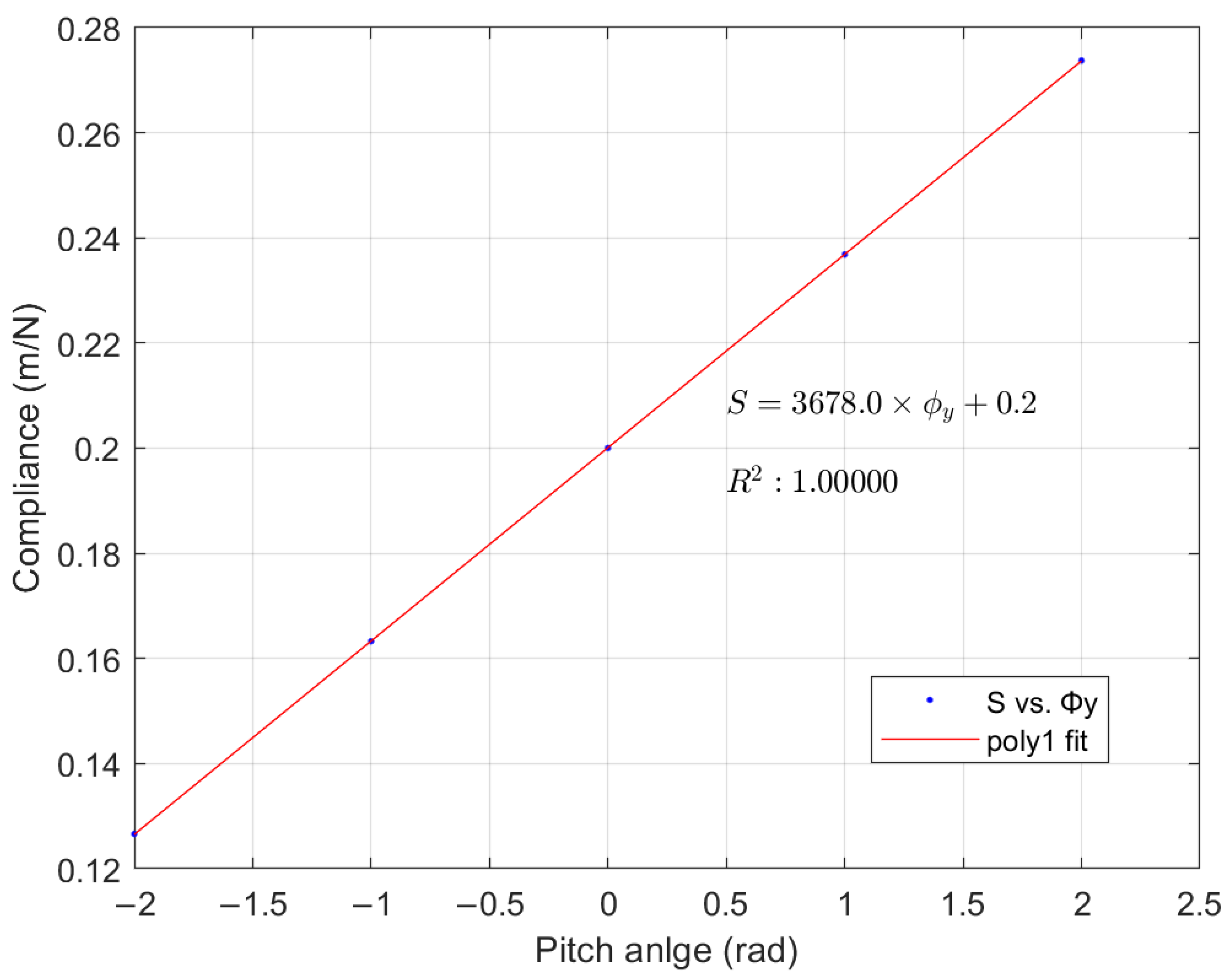
  • The dynamic equations of the torsion pendulum are reconstructed by adding a microgravity additional term that couples tilt and eccentricity to the static equilibrium. The stiffness of the deformation under test is decomposed into elastic stiffness and gravity stiffness, and the influence of center of mass offset and baseline tilt is linearized using the concept of compliance.
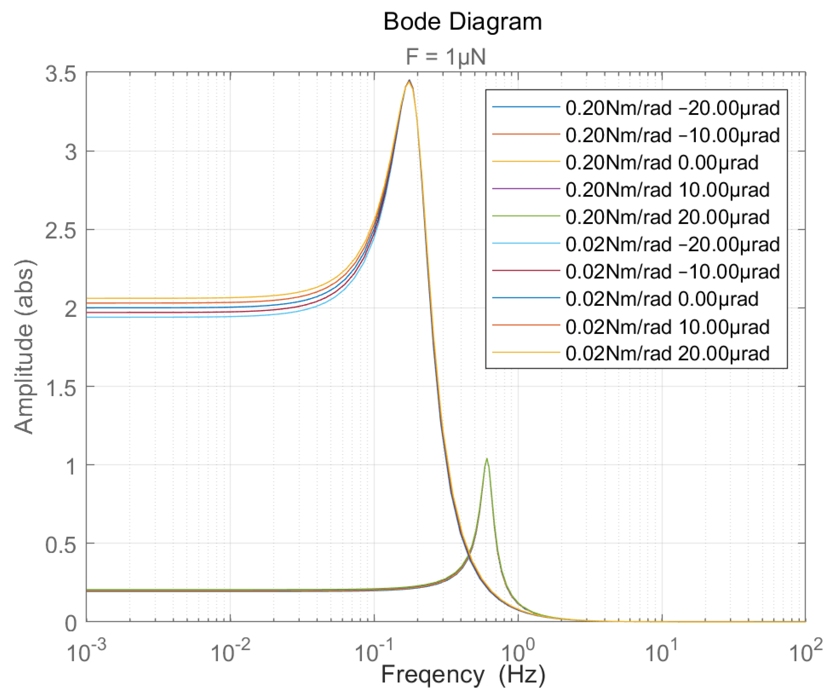
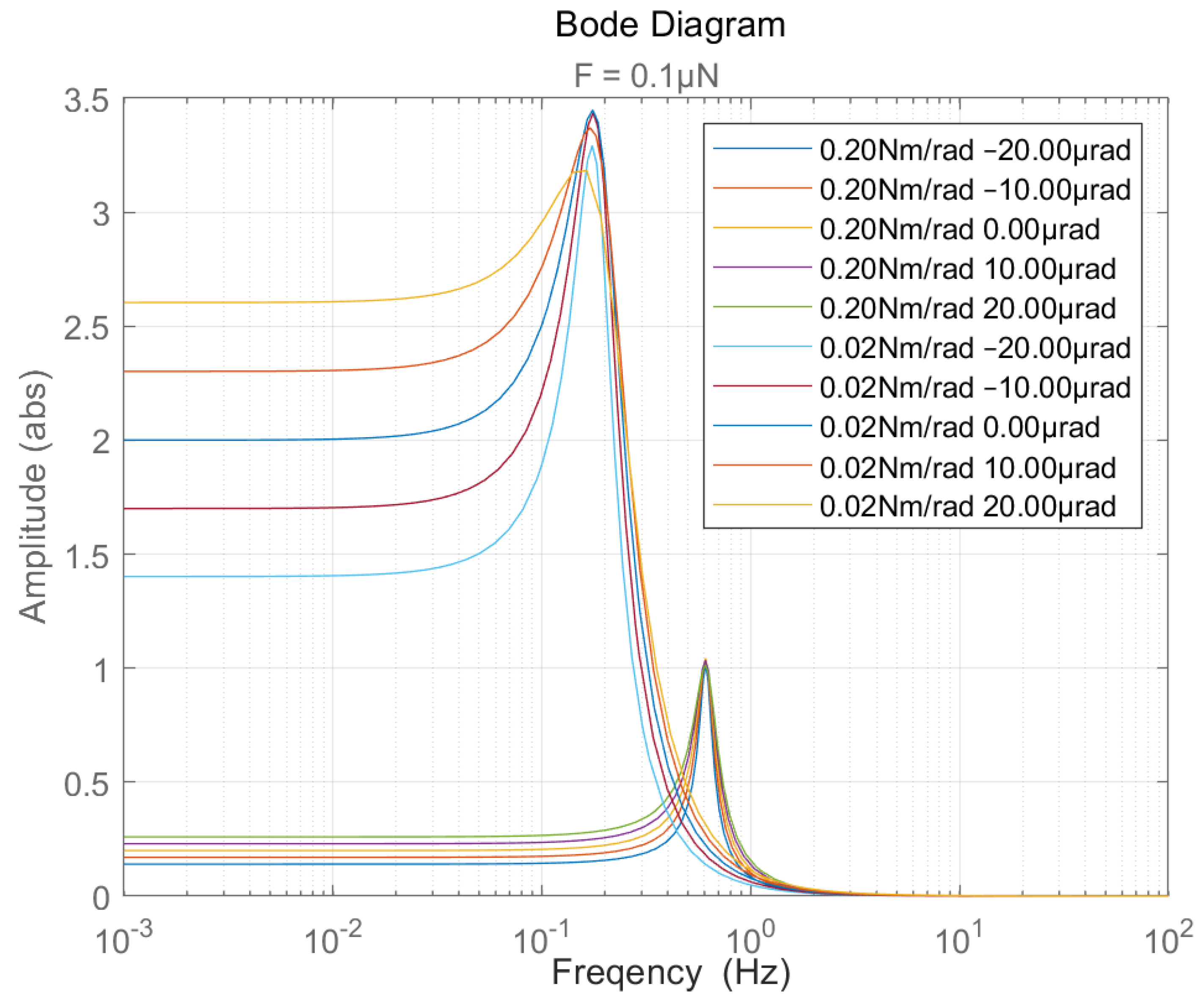
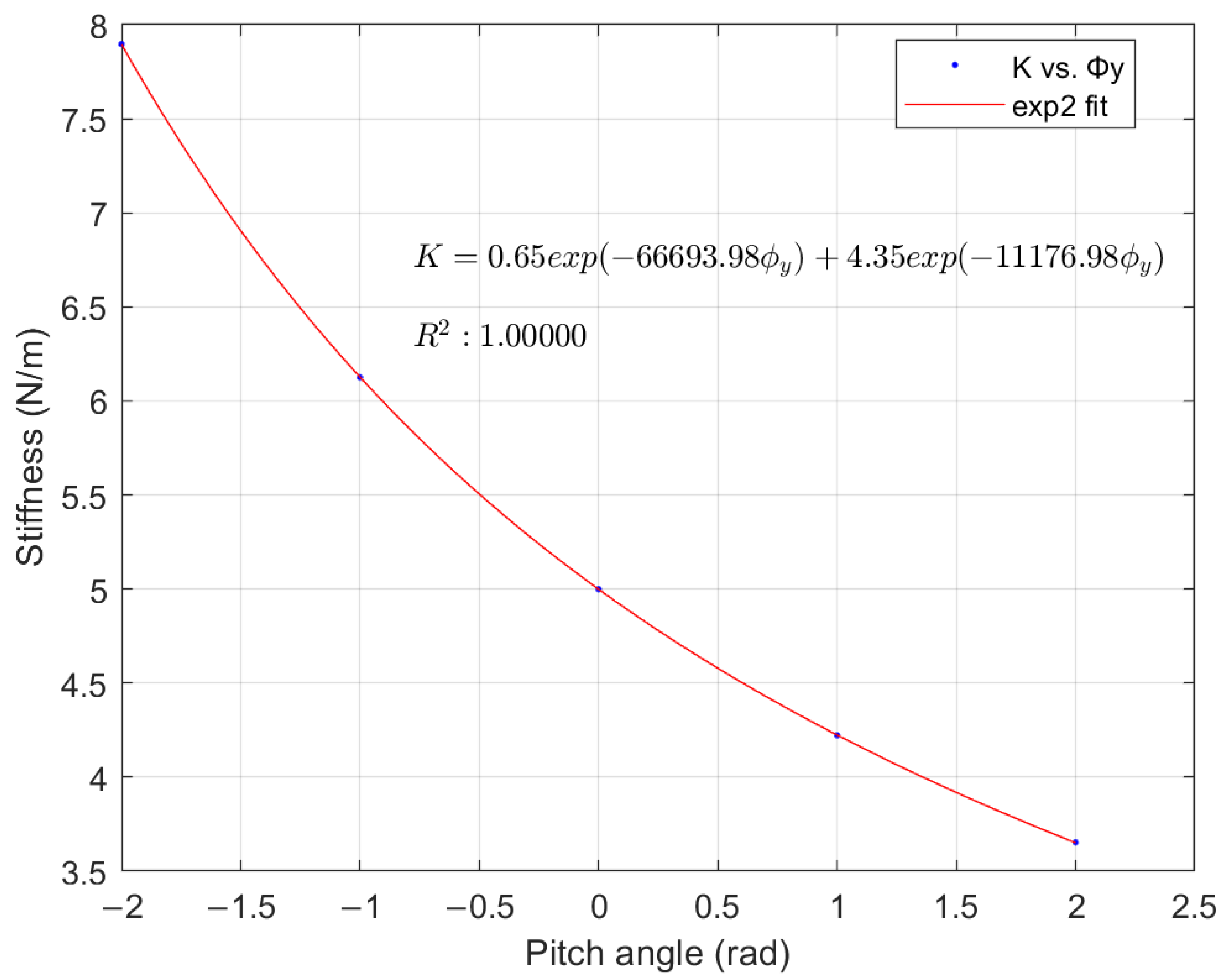
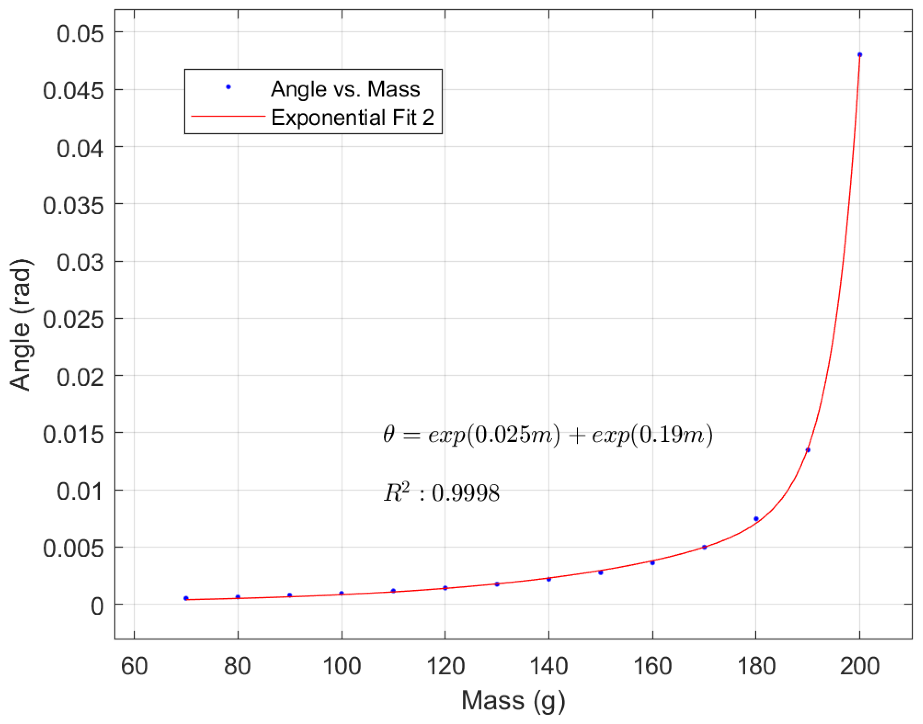
  • Using Simscape Multibody creatively to simulate the coupling effect of microgravity in the torsion pendulum, identifying the thrust position transfer function of the system, fitting the stiffness variation with a binomial exponential, and determining the error threshold of various factors that match the resolution force.
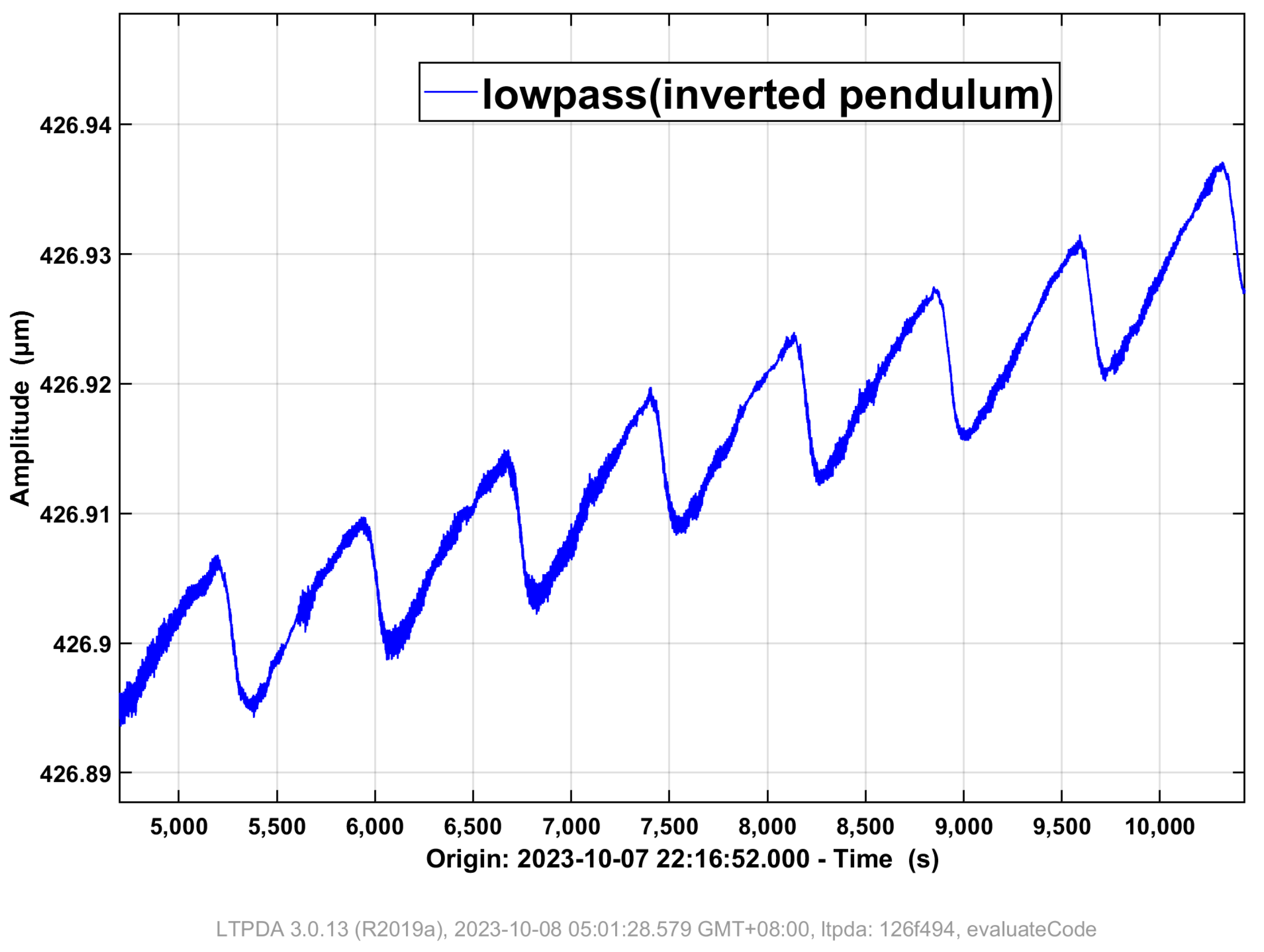
  • Using an inverted pendulum to detect the baseline tilt of the torsion pendulum, studying the optimization of the relationship between the counterweight and deformation and tilt amplification, and numerically analyzing the center of mass calibration based on amplitude-modulated thrust-tilt.
  • For the roll coupling of the torsion pendulum microgravity, the design of a baseline leveling mechanism driven by piezoelectric actuator is proposed. The effectiveness of detecting, modulating, and controlling the tilt change of the base is demonstrated through experiments without drag control.
  • The platform’s 2D tilt instability and the risk of baseline leveling failure can be reduced by using a two-stage pendulum to separate tilt and thrust. This approach has been preliminary simulated and validated, and will be further tested in future research.
In conclusion, based on the research work presented in this paper, we have learned that through simulation calculations and modulation testing, the center of mass position and platform tilt can be calibrated, and the torque applied by the pendulum frame gravity can be removed from the results, reducing the micro-thrust noise from thermal strain and ground vibrations. In preliminary experiments, after drag-free control of the platform, the tilt drift of the inverted pendulum at 0.1 mHz decreased from 5.7 μ m/Hz 1 / 2 to 0.28 μ m/Hz 1 / 2 , meeting the requirements for higher differential force accuracy and noise testing. In the future, we will further test the significant reduction in low-frequency noise of micro-thrusters under the expected baseline leveling and center of mass calibration under thermal load influence.

Author Contributions

Conceptualization, L.C. and C.Q.; methodology, L.C.; software, L.C.; validation, L.C., J.W. and J.L.; formal analysis, L.C.; investigation, L.C.; resources, C.Q.; data curation, C.Q.; writing—original draft preparation, L.C.; writing—review and editing, L.C.; visualization, H.D.; supervision, J.W.; project administration, J.M.; funding acquisition, C.Q. All authors have read and agreed to the published version of the manuscript.

Funding

This work was supported in part by the National Key Research and Development Program of China (2021YFC2202701), and the Major Scientific Instrument and Equipment Development Project of the Chinese Academy of Sciences (YJKYYQ20190059), and the Fundamental Research Funds for the Central Universities.

Institutional Review Board Statement

Not applicable.

Informed Consent Statement

Not applicable.

Data Availability Statement

Data will be available on request. The data are not publicly available due to confidentiality agreements and privacy regulations.

Conflicts of Interest

The authors declare no conflict of interest.

References

  1. Wu, Y.L.; Luo, Z.R.; Wang, J.Y.; Bai, M.; Zou, Z.M. China’s first step towards probing the expanding universe and the nature of gravity using a space borne gravitational wave antenna. Commun. Phys. 2021, 4, 34. [Google Scholar]
  2. Loomis, B.D.; Nerem, R.S.; Luthcke, S.B. Simulation study of a follow-on gravity mission to GRACE. J. Geod. 2012, 86, 319–335. [Google Scholar] [CrossRef]
  3. Hu, Z.; Wang, P.; Deng, J.; Cai, Z.; Wang, Z.; Wang, Z.; Yu, J.; Wu, Y.; Kang, Q.; Li, H.; et al. The drag-free control design and in-orbit experimental results of “Taiji-1”. Int. J. Mod. Phys. A 2021, 36, 2140019. [Google Scholar] [CrossRef]
  4. Wu, S.; Sun, X.; Zhang, Q.; Xiang, Y. Advances in Frontier Research of Space Gravitational Wave Detection Spacecraft Platform System. J. Deep. Space Explor. 2023, 10, 233–246. [Google Scholar]
  5. Yu, D.; Niu, X.; Wang, T.; Wang, S.; Zeng, M.; Cui, K.; Liu, H.; Tu, L.; Li, Z.; Huang, X.; et al. The developments of micro propulsion technology based on space gravitational wave detection task. Acta Sci. Nat. Univ. Sunyatseni/Zhongshan Daxue Xuebao 2021, 60, 194–212. [Google Scholar]
  6. Xu, H.; Mao, Q.; Gao, Y.; Wei, L.; Ding, Y.; Tu, H.; Song, P.; Hu, Z.; Li, Q. A newly designed decoupling method for micro-Newton thrust measurement. Rev. Sci. Instrum. 2023, 94, 014504. [Google Scholar] [CrossRef] [PubMed]
  7. Wang, J.; Long, J.; Xu, L.; Cong, L.; Guo, N.; Yang, W. A closed-loop torsional micro-thrust measurement system. Meas. Sci. Technol. 2023, 34, 125028. [Google Scholar] [CrossRef]
  8. Polk, J.; Pancotti, A.; Haag, T.; King, S.; Walker, M.; Blakely, J.; Ziemer, J. Recommended Practice for Thrust Measurement in Electric Propulsion Testing. J. Propuls. Power 2017, 33, 539–555. [Google Scholar] [CrossRef] [PubMed]
  9. Anselmo, M.R.; Marques, R.I. Torsional thrust balance for electric propulsion application with electrostatic calibration device. Meas. Sci. Technol. 2019, 30, 055903. [Google Scholar] [CrossRef]
  10. Mu, J.; Cong, L.; Hu, Q.; Qiao, C. Micro–Newton Thrust Stand Calibration Using Electrostatic Lantern Rings. IEEE Trans. Instrum. Meas. 2023, 72, 1–6. [Google Scholar] [CrossRef]
  11. Cong, L.; Mu, J.; Long, J.; Bai, S.; Guo, N.; Qiao, C. Experimental study on the response time of microthrust. Acta Mech. Sin. 2023, 39, 123095. [Google Scholar] [CrossRef]
  12. Ziemer, J.K. Performance measurements using a sub-micronewton resolution thrust stand. In Proceedings of the 27th International Electric Propulsion Conference, Pasadena, CA, USA, 15–19 October 2001; Volume 10. [Google Scholar]
  13. Trezzolani, F.; Magarotto, M.; Manente, M.; Pavarin, D. Development of a counterbalanced pendulum thrust stand for electric propulsion. Measurement 2018, 122, 494–501. [Google Scholar] [CrossRef]
  14. Gilpin, M.R.; McGehee, W.A.; Arnold, N.I.; Natisin, M.R.; Holley, Z.A. Dual-axis thrust stand for the direct characterization of electrospray performance. Rev. Sci. Instrum. 2022, 93, 065102. [Google Scholar] [CrossRef]
  15. Zhang, Y.; Guo, D.; Yang, Y. Design and Experimental Validation of a Micro–Newton Torsional Thrust Balance for Ionic Liquid Electrospray Thruster. Aerospace 2022, 9, 545. [Google Scholar] [CrossRef]
  16. Mahmood, K.; Ismail, N.A. Application of multibody simulation tool for dynamical analysis of tethered aerostat. J. King Saud Univ. Eng. Sci. 2022, 34, 209–216. [Google Scholar] [CrossRef]
  17. Cong, L.; Mu, J.; Liu, Q.; Wang, H.; Wang, L.; Li, Y.; Qiao, C. Thermal noise decoupling of micro-Newton thrust measured in a torsion balance. Symmetry 2021, 13, 1357. [Google Scholar] [CrossRef]
  18. Giurgiutiu, V. Stress, Vibration, and Wave Analysis in Aerospace Composites: SHM and NDE Applications; Academic Press: Cambridge, MA, USA, 2022. [Google Scholar]
  19. Xu, H.; Gao, Y.; Mao, Q.B.; Ye, L.W.; Hu, Z.K.; Zhang, K.; Song, P.; Li, Q. A compound pendulum for thrust measurement of micro-Newton thruster. Rev. Sci. Instrum. 2022, 93, 064501. [Google Scholar] [CrossRef] [PubMed]
  20. Lundberg, K.H.; Barton, T.W. History of inverted-pendulum systems. IFAC Proc. Vol. 2010, 42, 131–135. [Google Scholar] [CrossRef]
  21. Heinzel, G.; Wand, V.; García, A.; Jennrich, O.P.; Braxmaier, C.; Robertson, D.; Middleton, K.; Hoyland, D.; Rüdiger, A.; Schilling, R. The LTP interferometer and phasemeter. Class. Quantum Grav. 2004, 21, S581–S587. [Google Scholar] [CrossRef]
Figure 1. Definition of the coordinate system of torsion pendulum (isometric view).
Applsci 14 00091 g001
Figure 2. Angle definition of torsion pendulum roll direction (side view).
Applsci 14 00091 g002
Figure 3. Transfer function from thrust to displacement with stiffness values of 0.2 Nm/rad and 0.02 Nm / rad at thrust 1 μ N .
Applsci 14 00091 g003
Figure 4. Transfer function from thrust to displacement with stiffness values of 0.2 Nm / rad and 0.02 Nm / rad at thrust 0.1 μ N .
Applsci 14 00091 g004
Figure 5. Thrust stiffness fitting at different pitch angles.
Applsci 14 00091 g005
Figure 6. Thrust compliance fitting at different pitch angles.
Applsci 14 00091 g006
Figure 7. Tilt amplifying mechanism based on an inverted pendulum.
Applsci 14 00091 g007
Figure 8. Tilt angles amplified under different counter weights.
Applsci 14 00091 g008
Figure 9. Equivalent model of centroid shift of torsion pendulum (front view).
Applsci 14 00091 g009
Figure 10. Equivalent model of centroid shift of torsion pendulum (top view).
Applsci 14 00091 g010
Figure 11. Calibrating the centroid deviation of a torsion pendulum through applying thrust and tilt angle modulation with constant amplitude.
Applsci 14 00091 g011
Figure 12. The inverted pendulum detects the periodic signal of the platform tilt caused by the water cooler.
Applsci 14 00091 g012
Figure 13. Reference leveling mechanism based on piezoelectric actuators and lifting platform.
Applsci 14 00091 g013
Figure 14. Torsion pendulum and inverted pendulum displacement signals modulated by piezoelectric actuator square wave.
Applsci 14 00091 g014
Figure 15. Comparison of displacement ASD of inverted pendulum before and after tilt control.
Applsci 14 00091 g015
Figure 16. The concept model of a two-stage torsional pendulum.
Applsci 14 00091 g016
Figure 17. Microgravity decoupling of a two-stage torsion pendulum.
Applsci 14 00091 g017
Disclaimer/Publisher’s Note: The statements, opinions and data contained in all publications are solely those of the individual author(s) and contributor(s) and not of MDPI and/or the editor(s). MDPI and/or the editor(s) disclaim responsibility for any injury to people or property resulting from any ideas, methods, instructions or products referred to in the content.

