Article

Nanotomographic Analysis of Orthodontic Molar Tubes for Direct Bonding

by
Seweryn Kłos
1,
Joanna Janiszewska-Olszowska
2 and
Katarzyna Grocholewicz
2,*
1
Private Dental Practice “Dentysta Rodzinny” in Człuchów, 77-300 Człuchów, Poland
2
Department of Interdisciplinary Dentistry, Pomeranian Medical University in Szczecin, 70-111 Szczecin, Poland
*
Author to whom correspondence should be addressed.
Appl. Sci. 2024, 14(10), 4174; https://doi.org/10.3390/app14104174
Submission received: 23 March 2024 / Revised: 8 May 2024 / Accepted: 10 May 2024 / Published: 14 May 2024
(This article belongs to the Special Issue Innovative Approaches in Orthodontics Diagnostic and Dental Treatment)

Abstract

:
(1) Background: The most important part of an orthodontic attachment (bracket or tube) is the tube or slot for the insertion of the orthodontic wire. Aligning teeth along the archwire according to angular values preadjusted in the bracket slots (or tubes) requires a very precise size accordance between the archwires and slots. The aim of this study was to perform a nanotomographic analysis of the geometric features of molar tubes for direct bonding in terms of their dimensions and angles of their inner walls and analyze the presence of metallurgic imperfections. (2) Methods: Orthodontic tubes (n = 100) for upper right first molars from five different manufacturers (3M-Victory Series, Adenta-Bond Sing, Dentaurum-Ortho Cast M, GC-L LP, and ORMCO-Accent), 20 tubes each, were subjected to nanotomographic analysis. Measurements of the inner channel of the tubes, angles between the walls, and analysis of metallurgic imperfections were performed using high-resolution computed tomography. (3) Results: height measurements differed by 4–14% from ideal values declared by manufacturers, whereas the angles ranged from reducing by a maximum 1% comparing to values declared (hypodivergent walls) to increasing by a maximum 4.5% (divergent walls). (4) Conclusions: 1. The sizes of channels measured were slightly larger than those declared by manufacturers. 2. Slight deviations in wall parallelism and angles between the walls were found. 3. Some tubes were characterized by manufacturing defects of the metal. 4. Efforts should be made to further improve the production process of orthodontic attachments.

1. Introduction

Multibracket fixed appliances allow us to precisely move teeth in three directions of space as well as influence dental arch width or shape in order to gain space for malaligned or impacted teeth or close spaces in cases of missing teeth. Moreover, coordinating dental arches is possible if a mild discrepancy between the upper and lower arch widths exists [1]. A mild sagittal discrepancy or a minimally open bite may be solved by the use of intermaxillary elastics [2]. More severe malocclusions resulting from a skeletal discrepancy may require a complex interdisciplinary treatment including dental alignment and a subsequent surgical intervention [3], and recently, artificial intelligence has been included in treatment planning [4,5]. Thus, multibracket fixed appliances are mainly used to move teeth into the desired positions using light force in a precise and predictable way.
A fixed orthodontic appliance consists of brackets bonded to the teeth (incisors, canines, and premolars), molar abutments (tubes or brackets soldered to molar bands or bonded directly to the teeth), archwires, ligatures (wire or elastic), and accessories (elastic chains, springs, etc.). From the mechanical point of view, the most important part of the tube or bracket is the slot or tube channel, which hosts the archwire, aiding in transferring the force from the archwire to the periodontal ligament of the teeth to be moved.
Orthodontic molar tubes for direct bonding are among the basic elements of modern orthodontic fixed appliances, as in recent years, they have replaced cemented molar bands. The use of bands was associated with the fact that they have to be bought in different sizes, require trying on to find the proper size, and then must be pre-cleaned and sterilized [6]. Moreover, the cement distribution is uneven, with space between band and enamel surface not completely filled by the cement [7], and microleakage occurs between the cement–enamel interface [8], increasing susceptibility to caries and gingival inflammation. Oral hygiene is difficult with orthodontic bands [9], and thus, a more prolonged shift in subgingival microbiota comparing to bonded brackets is found [10].
The molar tubes available on the orthodontic market have usually a single tube, a base to be bonded directly to the enamel, and a hook for elastics. The rectangular molar tube channel hosts subsequently inserted (initially round and later rectangular) wires of increasing dimensions. Molar tubes are commercially available in two standard sizes (heights), 0.018- and 0.022-inch, which are chosen depending on the clinical preferences of the orthodontist. Various bondable molar tubes from different manufacturers are available on the market.
During orthodontic treatment with a fixed appliance, insertion of a rectangular archwire into a precise rectangular tube of the proper shape, orientation, and dimensions allows us to transfer orthodontic forces and force moments from the archwires to the periodontium in order to align the molars in three dimensions of space in the leveling phase at the initiation of the treatment. Subsequently, during space closure, as teeth are moved along the archwire, a proper accordance between the dimensions of the archwire and of the tube provides anti-tipping force moments, allowing for control of the dental tipping in order to achieve a more bodily tooth movement despite the force application point (to the tube) which is outside of the center of resistance of the tooth. Nevertheless, Kusy and Whitley [11], creating an algorithm based on the dimensions of archwires and brackets, showed that a minimal discordance between the two elements is a factor that has a significant impact on the sliding mechanics (e.g., the displacement of the archwire in the tube channel). Finally, in the finishing phase of fixed orthodontic treatment, a high precision of the tubes’ inner channel allows us to properly align the molar teeth into the dental arch in order to achieve a normal occlusion. Imprecision resulting from imperfect manufacturing processes may constitute an obstacle to reaching the desired final perfect positions of the teeth moved. Numerous studies can be found describing the precision of orthodontic brackets, regarding the concordance between slot heights declared by the manufacturers and those measured by instrumental analysis [12,13,14,15,16,17,18,19,20,21,22,23]; however, no papers have been found concerning the precision of orthodontic molar tubes channels.
Another important feature of the orthodontic brackets and tubes refers to the surface properties of their inner walls. It can be supposed that potential surface imperfections or artifacts of the inner walls of the brackets slots or molar tube channels may increase friction (especially during the leveling phase and during space closure in straight wire technique) and thus interfere with sliding mechanics or enhance corrosion of the alloy. The latter may lead to a release of ions contributing to gingival irritation or allergy. However, no studies were found referring to the topography of the inner wall surface of the molar tubes. Thus, the aim of the present study was to analyze the precision of the channels of molar tubes for direct bonding in terms of their dimensions and geometry, including parallelism of the inner walls and angles between the walls as well as the presence or absence of any metallurgic manufacturing imperfections in their inner walls.

2. Materials and Methods

The material consisted of 100 commercially available orthodontic 0.022 inch non-convertible molar tubes for the upper right first molar tooth, from five different manufacturers (20 tubes each), e.g., Accent (Ormco, Brea, CA, USA), Bond Sing N/Conv (Adenta, Gilching, Germany), Ortho Cast M-Series (Dentaurum, Ispringen, Germany), Victory Series (3M, Plymouth, MA, USA), L LP (GC Corporation, Tokyo, Japan). The tubes were ordered form the providers by the first author and used in sequence.
Initially, each of the tubes was subjected to three-dimensional scanning in a high-resolution computed tomography device (Waygate Technologies, Wunstorf, Germany), using the system GE v|tome|x s with a lamp of 240 kV (320 W), open. A handle for the brackets was designed for the purpose of the present study and made of extruded polystyrene (Styrodur, BASF, Ludwigshafen, Germany), chosen and used due to its low density. The appropriate resolution of the scanning was set by changing the geometric magnification, i.e., displacing the tested component between the lamp and the detector—the closer to the lamp, the greater the “shadow” and thus the resolution. Then, geometric calibration of the system was performed using a certified standard made of ruby balls connected by a carbon fiber.
Appropriate scanning parameters were selected to ensure the appropriate permeability of the X-ray beam: voltage: 180 kV, current intensity: 45 µA. After setting the scanning parameters, the detector calibration was performed, divided into two steps: offset: with radiation off, all scintillators are extinguished (“tared”); and gain: with the radiation on, all scintillators equalized to make the image as homogeneous as possible (the beam is conical, so in the center it has the highest energy, and the further from the center, the lower the energy—to eliminate this phenomenon, gain is performed).
Then, the scanning procedure was started: the device took 1200 photos rotating in steps, and the detector performed a gentle side-to-side movement between individual photos in order to avoid ring artifacts from the hardware—without additional software processing. Reconstruction was performed using u GE datos|x reconstruction workstation and software: BHC (beam hardening correction) filtering was used to eliminate the hardening effect of the beam (correct for the beam hardening artifacts that can occur when lower energy photons are absorbed more than higher energy photons as an X-ray beam passes through an object) to improve the quality of the CT images, reconstruction was performed, i.e., overlaying photos obtained by scanning on one another for full digitization.
Volume Graphics Studio MAX software was used for data processing in the following steps:
-
import of volumetric data to the software
-
definition (by the software) of the border between the material and the air, based on the gray scale histogram
-
data saving to the STL (Standard Triangulation Language) triangle mesh format
The reliability of the measurements was ensured by high precision and a proper calibration of the equipment used. All measurements were performed by one experienced operating engineer.
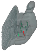
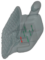
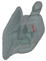
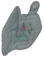
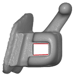
The heights of each tube channel were measured in millimeters, according to the method described in the study by Cash et al. [12], as presented in Table 1.
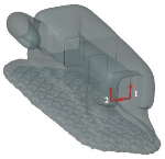
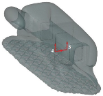
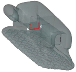
Subsequently, each tube channel was analyzed, referring to the angle between horizontal walls (reflecting wall parallelism) and angles between the perpendicular inner walls, as presented in Table 2.
Moreover, it was searched for any imperfections (manufacturing defects) on the inner walls of the channels and any defects in the structure of the metal of the tube.
The authors used as many samples as possible. However, for the linear measurements, with the standard deviation of maximum 0.01, assuming a 95% confidence level, the standard deviation = 0.01 and the clinical significance = 0.01 mm, the sample size yielded 6. For the angles assuming a 95% confidence level, standard deviation = 1.21 and the clinical significance = 1 degree, the sample yields 4.
Statistical analysis was performed using Software R, version 3.6.1. [24]. Data normality was verified by the use of the Shapiro–Wilk test. The level of significance was set at 0.05. Comparing quantitative variables between three and more groups was performed using analysis of variance (ANOVA) (for data of normal distribution) or the Kruskal–Wallis test (otherwise). In cases of detecting statistically significant differences, post-hoc analysis was performed using the LSD Fisher test (for normal distribution) or the Dunn test (otherwise), in order to identify groups differing statistically significantly.

3. Results

Characteristics of the groups of specimens referring to the measurements and assessment performed have been presented in Table 3 and Table 4.
The results of the present study obtained for height measurements (heights from 1 to 6) of the molar tubes are in the range of 4–14% different from ideal values declared by the manufacturers.
The results of the present in vitro research obtained for the angles from 1 to 6 ranged from reducing the angle by a maximum of about 1% compared to values declared by the manufacturer (hypodivergent walls) to increasing it by a maximum of about 4.5% of the angles (divergent walls).
The results of the present laboratory research also show that the buccal tubes manufactured by GC and Ormco are characterized by the highest accuracy as far as maintaining the declared linear and angular dimensions is concerned.
The worst results were recorded for the Adenta tubes, where apart from the statistically significant differences in the dimensions of the tube channels in relation to the nominal values (p < 0.001), production imperfections in the form of defects in the internal structure of the alloy were found. No metallurgical defects were found in the structure of the analyzed tubes from other manufacturers.
Comparison of the tubes inspected (post hoc analysis) revealed that all mean heights in all study samples were statistically significantly (p < 0.001) higher than those declared by the manufacturers:
-
The largest height 1 was found for Bond Sing and the lowest was found for Accent and Ortho Cast M.
-
Height 2 for Accent and Ortho Cast M was lower than for the remaining samples.
-
Height 3 was the largest for Bond Sing and the lowest for Accent.
-
The largest height 4 was found for Bond Sing comparing to all the remaining samples.
-
Height 5 was the largest for Bond Sing and the lowest for L LP
-
Height 6 was the largest for Bond Sing and the lowest for Ortho Cast M, L LP and Victory.
The angle between the horizontal walls of the channel was significantly higher (i.e., the walls were less parallel) in the Bond Sing tubes. The most parallel walls were found in the Ortho Cast M and L LP tubes.
It was visibly apparent that the angles between the inner walls of the channels slightly differed from the ideal 90 degrees:
-
Angle 1 was significantly higher for Victory Series than for Bond Sing and Ortho Cast M. Moreover, the difference between median value and the right angle was significantly higher for L LP, Accent and Bond Sing than for Ortho Cast M, where the angle was less than 90 degrees.
-
Angle 2 was the closest to ideal in Accent and was significantly different compared to the other samples.
-
Angle 3 differed from 90 degrees significantly more for L LP, Accent, and Bond Sing than for Victory Series and Ortho Cast M.
-
Angle 4 was significantly higher for Bond Sing compared to all other samples; for Victory Series and L LP, the angle was less than 90 degrees; for Accent, the angle was the closest to ideal. The difference between median value and the right angle was significantly higher for Ortho Cast M than for L LP and Accent, and for Victory Series, significantly higher than for Accent.
-
Angle 5 was the farthest and had the greatest median value for Victory Series, and for Accent, the angle was the closest to 90 degrees.
-
Angle 6 was found to have a difference between median and right angle which was significantly higher for Accent than for the latter samples; moreover, for Ortho Cast M, it was significantly lower than for L LP and Bond Sing.
Metallurgic imperfections were found only in Accent tubes, and the number of artifacts ranged from 3 to 6, as outlined in Figure 1.
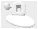
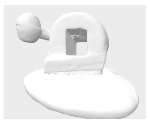
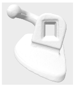
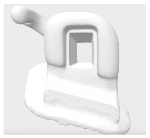
The appearance of the typical molar tubes (two specimens for each brand analyzed) has been presented in Table 4. It is visibly apparent that only in Bond Sing tubes are defects of the inner walls of the channel evident. The walls of the other tube channels seem regular and smooth.

4. Discussion

Contemporary orthodontic treatment, despite proper diagnostics and treatment planning, requires knowledge of the quality requirements for elements of the fixed appliance, in order to enhance the proper selection of orthodontic materials, especially brackets, tubes, and wires, providing orthodontic forces which are transferred to the teeth. A high quality of orthodontic materials might have an important influence on the results of fixed orthodontic treatment. Orthodontic brackets and tubes should allow us to achieve smooth sliding mechanics for a perfect dental alignment and ideal occlusion. Thus, they should be characterized by a precise geometry, perfect dimensions, and a smooth surface.
An important quality issue is how orthodontic brackets are manufactured. In this regard, significant progress has been made over the past few decades, from casting and milling techniques to the metal injection moulding (MIM) method [12,22,25]. The MIM method was developed in the United States in the early 1980s and has been applied to the production of small parts [23]. The molding technique uses pre-prepared molds that are poured with a liquid metal alloy. Milling involves machining a metal rail, while the injection molding (MIM) method involves introducing metal powders mixed with an organic binder into a prepared mold under pressure, using an injection molding machine. Then, in the baking process, the polymer is burned away and the metal is fused together. The recipient of the product, i.e., the doctor, is not in a position to assess the precision of the bracket’s manufacture. However, the treatment obtained may influence the choice of supplier for the future consecutively treated patients. However, it should be remembered that this evaluation is subjective, as many other factors influence the treatment effect [26,27].
Manufacturers of orthodontic brackets are reluctant to provide any information on how and what the manufacturing process is, while they spend huge amounts of money on promoting their products, claiming that they are selling the highest quality brackets.
The body of an orthodontic molar tube contains the tube channel for the archwire and a hook protruding from its wall towards the gingival margin of the molar tooth. The base of the tube serves for bonding the tube to the tooth buccal surface. From Table 5, it is apparent that in most cases, the body and the base are manufactured separately and then soldered together, as the soldering can be visually identified. Interestingly, in most tubes, the hook consists of two halves which are joined together in apparently imperfect way. This finding might potentially have an influence on the bending strength and breaking susceptibility.
However, a recent review of the literature has confirmed that orthodontic brackets are characterized by different manufacturing imperfections that may occur in a single bracket, a specific set, or in a whole series of orthodontic brackets [28]. Referring to orthodontic brackets, numerous studies assessing accordance to perfect slot dimensions have been found [12,13,14,15,16,17,18,19,20,21,23]. It was revealed that orthodontic bracket slots were usually oversized, referring to the declared heights of 0.018 or 0.022 inches. According to the literature, the heights of the slots of orthodontic brackets differed by 0.5% to 30%, referring to values declared by the manufacturers. In absolute values, the differences ranged from 0.008 inches to 0.01 inches [12,13,14,15,16,17,18,19,20,21,22,23]. Oversized bracket slots may result in a more pronounced tipping during space closure and imperfect finishing. Subsequently, bracket rebonding with overcorrection or wire bending may be required.
The results of the present study, obtained for molar tubes, are in the range of 4–14% for height measurements. The manufacturers of the molar tubes evaluated in the present study do not specify how they are produced; thus, the authors have no reliable information regarding what methods were used for the manufacturing. It seems possible that the differences in dimensions of the molar tubes reported in the present study and the occurrence of artifacts are due to differences in the production methods of the evaluated molar tubes.
The present study is the first investigation analyzing the dimensions of orthodontic molar tubes. For all the tubes, upper right molars were chosen in order to ensure a uniformity of the investigation, as the authors intended to compare the quality of different molar tubes. The ideal size of the tube channel should be as declared by the manufacturer, e.g., height of 0.018 inches (0.4572 mm) or 0.022 inches (0.5588 mm). The present findings revealed that 0.022-inch orthodontic molar tubes are characterized by increased heights comparing to the declared values, similarly as most orthodontic brackets.
In an ideal situation, the upper and lower inner walls of the bracket slots and molar tubes should be parallel in order to host a rectangular wire and allow for proper expression of the torque, i.e., proper orientation of the roots referring to the vestibular and palatal or lingual cortical bone. A twisted archwire providing torsional torquing moments exerts a pressure with its corners on the parallel inner walls of the molar tube. A divergent bracket or tube is thus characterized by increased slot play (free movement of the loose archwire in the slot or tube without exerting force on the tooth) reducing torque expression. No studies that could be used for comparison and discussion, referring to the parallelism of the opposing inner walls of orthodontic molar tubes, could be found in the available scientific literature. It is evident that a hypodivergent bracket or molar tube may increase friction and hinder the movement of the bracket along the archwire, creating an obstacle for sliding mechanics or even completely blocking sliding of the archwire within the fixed appliance. Referring to the literature on the parallelism of the inner walls of orthodontic brackets, some brackets were hypodivergent [13,17] and some were hyperdivergent [13,21,22]. Similarly, according to the present study, the inner walls of the molar tubes are not perfectly parallel. The results of the present investigations show that the opposite upper and lower walls of the molar tubes are slightly hyperdivergent. This geometric feature may potentially reduce torque expression, thus enhancing buccal molar tipping during dental expansion or hindering perfect torque adjustment of posterior teeth to reach ideal occlusion.
In an ideal situation, a perfect geometry of the molar tube should be associated with 90 degree angles between the adjacent perpendicular walls. No previous studies have been found referring to the geometry of molar tubes, which could be used for comparison and discussion. The literature on orthodontic brackets reveals various ranges of deviation from the ideal 90 degrees. Conversely, the results of the present investigation referring to 6 angles measured between the adjacent inner walls of the tubes indicate an acceptable precision, as revealed deviations ranged from reduction of an angle by a maximum 1% to its increase by a maximum 4.5%. The range of variation in buccal tube dimensions was therefore found to be similar to that characterizing orthodontic brackets. No studies were found in the literature that could be used for comparison with the results of the present study regarding the metallurgical imperfections of orthodontic brackets.
Another important aspect of the quality of orthodontic materials is a smooth surface of the bracket slot and of the inner walls of orthodontic molar tubes. The present analysis of the molar tubes in nanotomography allowed to visualize their structural imperfections. The defects found in the molar tubes by a single manufacturer may potentially accumulate biofilm or food remnants and thus enhance corrosion or increase friction. No other studies were found in the literature that analyze orthodontic molar tubes or brackets in computed nanotomography that could be compared or discussed with the present results.
In a perfect clinical setting, an ideal positioning of precise, perfectly manufactured smooth brackets and tubes on all the teeth, followed by the insertion of properly sized smooth archwires, should allow for unimpeded performance of straight wire orthodontic treatment without the necessity of introducing compensatory wire bends and without hindering sliding mechanics by excessive friction. A proper selection of high-quality orthodontic materials might possibly significantly influence the treatment time, the clinical excellence, and patients’ satisfaction. Manufacturers should constantly make efforts to provide brackets and tubes with comfortable shapes, smooth surfaces, perfect slot orientation, and precision in order to enhance ideal treatment results.
Referring to future studies, it could be interesting to measure the roughness of the inner walls of the molar tubes. However, due to limited access to the inner walls of the molar tubes for instrumental measurement, an investigation of their roughness would require carefully planning the study design and methods.
Moreover, it could be interesting to compare molar tubes and check for uniformity between the sides or dental arches within the same brands of molar tubes. In fact, it was noticed that tubes of the same brand had slightly different geometric features.
The present study is of clinical importance, as a practitioner is not able to clinically assess the quality of orthodontic molar tubes in terms of the nanofeatures of the tube canal. The authors are of the opinion that a limitation of the study refers to its laboratory nature. The clinical significance of the findings can only be supposed. Moreover, the study is limited to one tube size and does not comprise tubes soldered to orthodontic bands.
The authors are convinced that studies on orthodontic brackets, wires, and tubes published in scientific journals independent from manufacturers provide a constant motivation to improve the quality of orthodontic materials.

5. Conclusions

The sizes of channels of orthodontic molar tubes were slightly larger than those declared by the manufacturers. Slight deviations in wall parallelism and angles between the walls were found. Some tubes were characterized by manufacturing defects in the metal. Efforts should be made to further improve the production process of orthodontic attachments.

Author Contributions

Conceptualization, S.K. and J.J.-O.; methodology, S.K. and J.J.-O.; software S.K., J.J.-O. and K.G.; validation, S.K., J.J.-O. and K.G.; formal analysis, S.K. and J.J.-O.; investigation S.K. and J.J.-O.; resources, S.K. and J.J.-O.; data curation, S.K.; writing—original draft preparation, S.K., K.G. and J.J.-O.; writing—review and editing, K.G.; visualization, S.K.; supervision, J.J.-O. and K.G.; project administration, S.K. and J.J.-O.; funding acquisition, K.G. All authors have read and agreed to the published version of the manuscript.

Funding

This research received no external funding.

Data Availability Statement

All raw data are available upon request from corresponding author.

Conflicts of Interest

The authors declare no conflicts of interest.

References

  1. Arreghini, A.; Lombardo, L.; Mollica, F.; Siciliani, G. Torque expression capacity of 0.018 and 0.022 bracket slots by changing archwire material and cross section. Prog. Orthod. 2014, 25, 53. [Google Scholar] [CrossRef] [PubMed]
  2. Farret, M.M. Orthodontic biomechanics with intermaxillary elastics. Dental Press J. Orthod. 2023, 28, e23spe3. [Google Scholar] [CrossRef]
  3. Zammit, D.; Ettinger, R.E.; Sanati-Mehrizy, P.; Susarla, S.M. Current Trends in Orthognathic Surgery. Medicina 2023, 59, 2100. [Google Scholar] [CrossRef] [PubMed]
  4. Ahn, H.J.; Byun, S.H.; Baek, S.H.; Park, S.Y.; Yi, S.M.; Park, I.Y.; On, S.W.; Kim, J.C.; Yang, B.E. A comparative analysis of artificial intelligence and manual methods for Three-Dimensional anatomical landmark identification in dentofacial treatment planning. Bioengineering 2024, 27, 318. [Google Scholar] [CrossRef]
  5. Kazimierczak, N.; Kazimierczak, W.; Serafin, Z.; Nowicki, P.; Nożewski, J.; Janiszewska-Olszowska, J. AI in orthodontics: Revolutionizing diagnostics and treatment planning—A comprehensive review. J. Clin. Med. 2024, 13, 344. [Google Scholar] [CrossRef]
  6. Irfan, S.; Irfan, S.; Fida, M.; Ahmad, I. Contamination assessment of orthodontic bands after pre-cleaning methods at a tertiary care hospital. J. Orthod. 2019, 46, 220–224. [Google Scholar] [CrossRef]
  7. Radlanski, R.J.; Renz, H.; Reulen, A. Distribution of the cement film beneath the orthodontic band: A morphometric in vitro study. J. Orofac. Orthop. 2003, 64, 284–292. [Google Scholar] [CrossRef] [PubMed]
  8. Uysal, T.; Ramoglu, S.I.; Ertas, H.; Ulker, M. Microleakage of orthodontic band cement at the cement-enamel and cement-band interfaces. Am. J. Orthod. Dentofac. Orthop. 2010, 137, 534–539. [Google Scholar] [CrossRef]
  9. Erbe, C.; Hornikel, S.; Schmidtmann, I.; Wehrbein, H. Quantity and distribution of plaque in orthodontic patients treated with molar bands. J. Orofac. Orthop. 2011, 72, 13–20. [Google Scholar] [CrossRef]
  10. Chen, I.; Chung, J.; Vella, R.; Weinstock, G.M.; Zhou, Y.; Jheon, A.H. Alterations in subgingival microbiota during full-fixed appliance orthodontic treatment—A prospective study. Orthod. Craniofac. Res. 2022, 25, 260–268. [Google Scholar] [CrossRef]
  11. Kusy, R.; Whitley, J. Assessment of second-order clearances between orthodontic archwires and bracket slots via the critical contact angle for binding. Angle Orthod. 1999, 69, 71–80. [Google Scholar] [PubMed]
  12. Cash, A.C.; Good, S.A.; Curtis, R.V.; McDonald, F. An evaluation of slot size in orthodontic brackets—Are Standards as Expected? Angle Orthod. 2004, 74, 450–453. [Google Scholar] [PubMed]
  13. Meling, T.R.; Odegaard, J.; Segner, D. On bracket slot height: A methodologic study. Am. J. Orthod. Dentofac. Orthop. 1998, 113, 387–393. [Google Scholar]
  14. Demling, A.; Dittmer, M.P.; Schwestka-Polly, R. Comparative analysis of slot dimension in lingual bracket system. Head Face Med. 2009, 15, 5–27. [Google Scholar] [CrossRef] [PubMed]
  15. Bhalla, N.B.; Good, S.A.; McDonald, F.; Sherriff, M.; Cash, A.C. Assessment of slot sizes in self-ligating brackets using electron microscopy. Aust. Orthodox. J. 2010, 26, 38–41. [Google Scholar] [CrossRef]
  16. Joch, A.; Pichelmayer, M.; Weiland, F. Bracket slot and archwire dimensions: Manufacturing precision and third order clearance. J. Orthod. 2010, 37, 241–249. [Google Scholar] [CrossRef]
  17. Major, T.W.; Carey, J.P.; Nobes, D.D.; Major, P.W. Orthodontic bracket manufacturing tolerances and dimensional differences between select self-ligating brackets. J. Dent. Biomech. 2010, 27, 781321. [Google Scholar] [CrossRef]
  18. Pai, V.S.; Pai, S.S.; Krishna, S.; Swetha, M. Evaluation of slot size in orthodontic brackets: Are standards as expected? J. Ind. Orthod. Soc. 2011, 45, 169–174. [Google Scholar] [CrossRef]
  19. Brown, P.; Wagner, W.; Choi, H. Orthodontic bracket slot dimensions as measured from entire bracket series. Angle Orthod. 2015, 85, 678–682. [Google Scholar] [CrossRef]
  20. Ancona, M.A.; Díaz, R.R.; Rodríguez, F.M.; Olvera, S.P. Variations in slot size of self-ligating brackets: Variación en el tamaño de la ranura de brackets de autoligado. Rev. Mex. De Ortod. 2015, 3, 224–227. [Google Scholar]
  21. Lee, Y.; Lee, D.Y.; Kim, Y.J. Dimensional accuracy of ceramic self-ligating brackets and estimates of theoretical torsional play. Angle Orthod. 2016, 86, 804–809. [Google Scholar] [CrossRef] [PubMed]
  22. Alavi, S.; Tajmirriahi, F. Assessment of dimensional accuracy of preadjusted metal injection molding orthodontic brackets. Dent. Res. J. 2016, 13, 440–445. [Google Scholar]
  23. Erduran, R.H.; Maeda, F.A.; Ortiz, S.R.; Triviño, T.; Fuziy, A.; Carvalho, P.E. Analysis on the precision of the dimensions of self-ligating brackets. Microsc. Res. Tech. 2016, 79, 1188–1192. [Google Scholar] [CrossRef] [PubMed]
  24. R Core Team. R: A Language and Environment for Statistical Computing; R Foundation for Statistical Computing: Vienna, Austria, 2019; Available online: https://www.R-project.org/ (accessed on 16 October 2023).
  25. Floria, G.; Franchi, L. Metal injection molding in orthodontics. Virtual J. Orthod. 1997, 2, 1. Available online: http://vjo.it/five/mim (accessed on 25 June 2004).
  26. Vieira, E.P.; Watanabe, B.S.; Pontes, L.F.; Mattos, J.N.; Maia, L.C.; Normando, D. The effect of bracket slot size on the effectiveness of orthodontic treatment: A systematic review. Angle Orthod. 2018, 88, 100–106. [Google Scholar] [CrossRef] [PubMed]
  27. Moresca, R. Orthodontic treatment time: Can it be shortened? Dental Press J. Orthod. 2018, 23, 90–105. [Google Scholar] [CrossRef]
  28. Kłos, S.; Janiszewska-Olszowska, J. Precision of the dimensions of orthodontic bracket slots—Systematic review. Pomeranian J. Life Sci. 2019, 65, 62–71. [Google Scholar] [CrossRef]
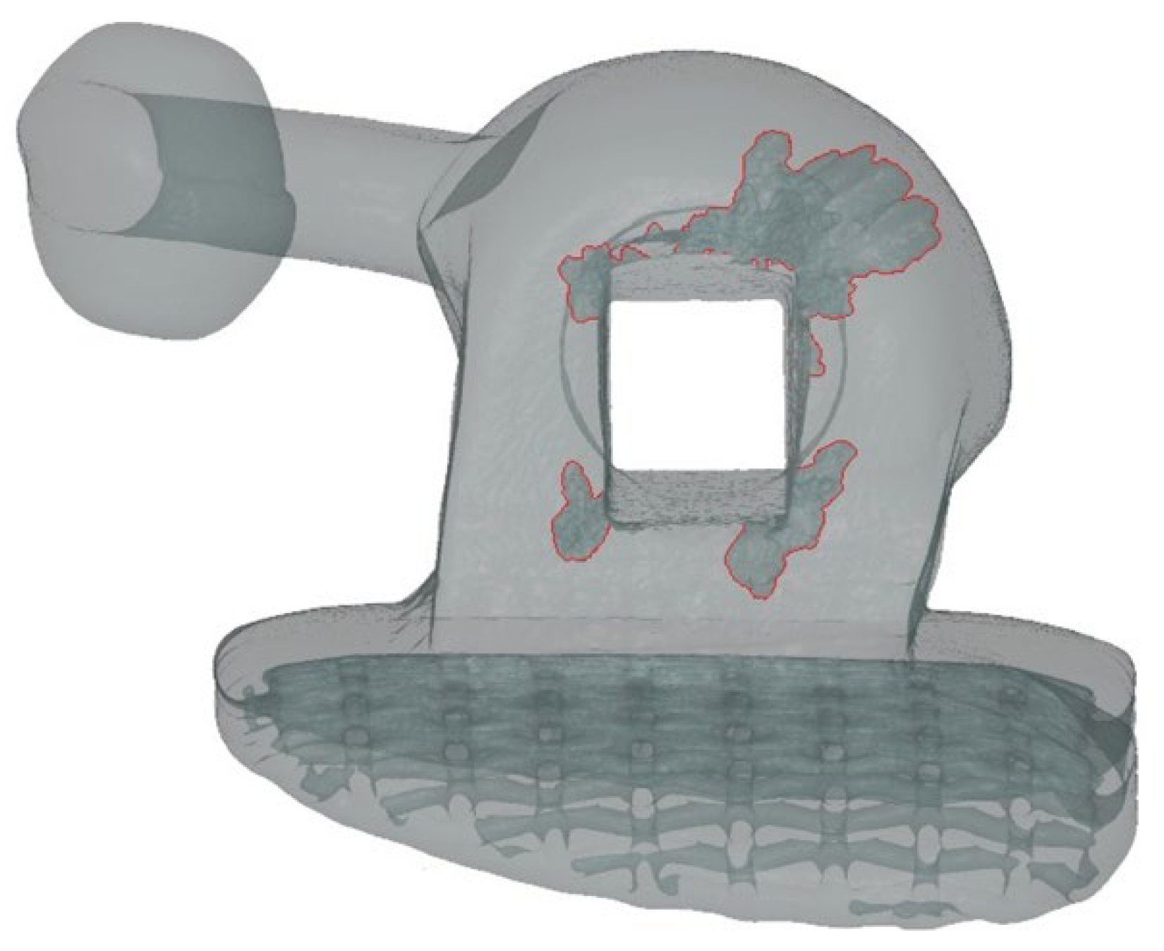
Figure 1. A Bond Sing tube with four metallurgic imperfections.
Applsci 14 04174 g001
Table 1. Linear measurements of the inner walls of the molar tubes (marked in red).
Measurements of each tube channel dimensions
Height 1 of the upper inner wall at its distal endHeight 2 of the lower inner wall at its distal end.
Applsci 14 04174 i001Applsci 14 04174 i002
Height 3 of the upper inner wall in the middle of its lengthHeight 4 of the lower inner wall in the middle of its length
Applsci 14 04174 i003Applsci 14 04174 i004
Height 5 of the upper inner wall at its mesial endHeight 6 of the lower inner wall at its mesial end
Applsci 14 04174 i005Applsci 14 04174 i006
Table 2. Angular measurements of the inner walls of the molar tubes.
Angles between the walls of each tube channel
Angle between horizontal wallsAngles 1 and 2 between the walls on the distal end of the tube
Applsci 14 04174 i007Applsci 14 04174 i008
Angles 3 and 4 between the walls in the middle of the tubeAngles 5 and 6 between the walls on the mesial end of the tube
Applsci 14 04174 i009Applsci 14 04174 i010
Table 3. Distribution of the linear variables measured and results of post-hoc analysis.
VariableAccent
(Ormco)
Bond Sing
(Adenta)
Ortho Cast M (Dentaurum)Victory
Series (3M)
L LP
(GC)
p *
Height 1
[mm]
mean ± SD0.56 ± 0.010.56 ± 0.120.56 ± 0.00.58 ± 0.010.57 ± 0.0<0.001
NP
median0.560.590.560.580.57
Q1–Q30.56–0.570.58–0.590.56–0.570.58–0.590.56–0.57
Height 2
[mm]
mean ± SD0.56 ± 0.00.57 ± 0.010.56 ± 0.00.57 ± 0.010.57 ± 0.0<0.001
P
median0.560.570.560.570.57
Q1–Q30.56–0.560.57–0.580.56–0.560.57–0.580.57–0.57
Height 3
[mm]
mean ± SD0.56 ± 0.00.65 ± 0.010.57 ± 0.00.57 ± 0.010.57 ± 0.0<0.001
P
median0.560.650.570.570.57
Q1–Q30.56–0.560.64–0.650.56–0.570.57–0.580.57–0.57
Height 4
[mm]
mean ± SD0.57 ± 0.00.63 ± 0.010.57 ± 0.00.57 ± 0.010.57 ± 0.0<0.001
NP
median0.570.630.570.570.57
Q1–Q30.57–0.570.63–0.640.57–0.570.57–0.570.57–0.57
Height 5
[mm]
mean ± SD0.57 ± 0.00.64 ± 0.010.57 ± 0.00.59 ± 0.00.56 ± 0.0<0.001
NP
median0.570.640.570.590.56
Q1–Q30.57–0.570.63–0.640.57–0.570.58–0.590.56–0.56
Height 6
[mm]
mean ± SD0.58 ± 0.00.63 ± 0.010.57 ± 0.00.57 ± 0.010.57 ± 0.0<0.001
P
median0.570.630.570.580.56
Q1–Q30.57–0.580.62–0.630.57–0.570.57–0.580.56–0.57
Table 4. Distribution of the angular variables measured, and artifacts found and results of post-hoc analysis.
Angle between Horizontal Walls
[Degrees]
mean ± SD0.04 ± 0.010.08 ± 0.030.03 ± 0.040.04 ± 0.010.02 ± 0.0<0.001
NP
median0.040.070.020.040.02
Q1–Q30.03–0.040.06–0.080.02–0.020.03–0.040.02–0.02
Angle 1
[degrees]
mean ± SD90.85 ± 1.2190.21 ± 0.4289.77 ± 0.4890.85 ± 2.0690.23 ± 0.220.001
NP
median90.6590.1589.7290.7790.27
Q1–Q390.21–91.0889.97–90.4789.31–9089.38–92.4790.15–90.33
Angle 2
[degrees]
mean ± SD90.05 ± 0.6390.21 ± 0.4589.98 ± 0.4589.57 ± 0.9589.32 ± 0.37<0.001
NP
median90.0690.490.189.9189.28
Q1–Q389.68–90.5490.01–90.4589.8–90.2488.39–91.0889.11–89.53
Angle 3
[degrees]
mean ± SD88.99 ± 0.7690.77 ± 0.9789.04 ± 0.3190.93 ± 1.590.12 ± 0.6<0.001
NP
median88.8990.3589.0690.7589.99
Q1–Q388.52–89.2990.06–91.5788.8–89.1989.57–92.0389.69–90.34
Angle 4
[degrees]
mean ± SD90.3 ± 0.5194.54 ± 2.5890.75 ± 0.3189.63 ± 1.5889.23 ± 0.7<0.001
P
median90.4294.0190.7289.6989.44
Q1–Q389.84–90.6593.62–95.6890.53–90.9688.92–90.6788.83–89.72
Angle 5
[degrees]
mean ± SD89.69 ± 0.5891.2 ± 7.1689.61 ± 0.3191.85 ± 1.488.88 ± 1.36<0.001
NP
median89.5989.8189.6691.5789.12
Q1–Q389.28–90.0489.44–9089.39–89.8190.66–93.0988.93–89.3
Angle 6
[degrees]
mean ± SD89.63 ± 0.5187.72 ± 7.4889.93 ± 0.5489.04 ± 1.0790.61 ± 1.35<0.001
NP
median89.889.3289.9289.3590.41
Q1–Q389.24–89.9189.02–89.5389.69–90.2388.07–89.890.24–90.53
Number of artifactsmean ± SD0 ± 04.2 ± 1.540 ± 00 ± 00 ± 0<0.001
P
median04000
Q1–Q30–03–60–00–00–0
Table 5. Molar tubes inspected—examples of typical appearance of molar tubes inspected.
Accent (Ormco)
Applsci 14 04174 i011Applsci 14 04174 i012
Bond Sing (Adenta)
Applsci 14 04174 i013Applsci 14 04174 i014
Ortho Cast M (Dentaurum)
Applsci 14 04174 i015Applsci 14 04174 i016
Victory Series (3M)
Applsci 14 04174 i017Applsci 14 04174 i018
L LP (GC)
Applsci 14 04174 i019Applsci 14 04174 i020
Disclaimer/Publisher’s Note: The statements, opinions and data contained in all publications are solely those of the individual author(s) and contributor(s) and not of MDPI and/or the editor(s). MDPI and/or the editor(s) disclaim responsibility for any injury to people or property resulting from any ideas, methods, instructions or products referred to in the content.