Article

Design and Validation of New Methodology for Hydraulic Passage Integration in Carbon Composite Mechanisms

1
University of Evry Val d’Essonne-UPSaclay/KALYSTA Actuation, 40 Rue de Pelvoux, 91000 Evry, France
2
Laboratoire de Materiaux et Mecanique, ECAM Rennes, Campus de Ker Lann, 35170 Bruz, France
3
Robotics and Production System Department, Industrial Engineering and Robotics Faculty, National University of Science and Technology Politecnica, Splaiul Independentei nr. 313, 060042 Bucharest, Romania
4
IBISC Laboratory, University of Evry Val d’Essonne-UPSaclay, 91034 Évry, France
*
Author to whom correspondence should be addressed.
Appl. Sci. 2024, 14(11), 4378; https://doi.org/10.3390/app14114378
Submission received: 14 April 2024 / Revised: 18 May 2024 / Accepted: 20 May 2024 / Published: 22 May 2024
(This article belongs to the Section Robotics and Automation)

Abstract

:

Featured Application

The procedure is applied to assemble mechanisms manufactured with carbon composite materials which have hydraulic actuation.

Abstract

Humanoid robots have rapidly become the focus of research in recent years, with the most impressive humanoids being hydraulically actuated. This is due to the capacity of hydraulic actuation to provide simultaneous high forces with dynamic motion. The scarcity of hydraulic robots is mainly due to the difficulty in managing hydraulic pipes. These decrease the robot’s social acceptance and safety and are the main source of leaks. Recently, there has been a new trend in hydraulically actuated robots that involves creating internal oil passages within the robotic parts to eliminate the need for external flexible tubes. Developing these parts using carbon composite materials provides an additional advantage of ensuring lightweight yet robust robotic parts. However, assembling hydraulically integrated parts is challenging due to the leakproof requirement and the high pressures involved. This article proposes a new, reliable, and effective method that ensures a strong, leakproof assembly. A mathematical model with 11 parameters describing the assembly zone and accounting for geometric parameters, material characteristic parameters, and porosity has been developed. A numerical model was conducted to evaluate the effect of these parameters on the state of the assembly. Experimental validation was conducted to evaluate the assembly force. A satisfactory convergence between the mathematical model and the experimental results was observed with a maximum deviation of 20 % .

1. Introduction

Recent years have witnessed a technological revolution in the field of humanoid robotics. This has led to advances in all disciplines, particularly in actuation technologies. The choice of the actuating technology depends upon the application. Electric actuators are typically used for light tasks, notably for humanoid robots designed for social interaction. On the contrary, hydraulic actuators are used when high force is required. For example, the humanoid robot ATLAS from Boston Dynamics [1], SARCOS from Carnegie Mellon University [2], and HYDROïD, a full-size humanoid under development at Paris Saclay [3], are hydraulically actuated as they are destined to perform heavy-duty tasks. HYDROïD has 36 hydraulically actuated Degrees of Freedom consisting of multiple mechanisms designed to fit in a restrained volume to respond to an anthropomorphic design [4].
Amid this technological evolution, hydraulic actuation is proving its ability to provide a high force-to-weight ratio and a high force-to-volume ratio. Several advances have occurred in this domain where hydraulic cylinders became more electrically integrated and compact [5]. However, this technology requires the use of hydraulic tubes. The multitude of hydraulic tubes in humanoids has several disadvantages; they decrease their social acceptance, and the tubes face the danger of tearing off, which puts the global function of the system at risk. A compromise must, therefore, be made between the advantages and disadvantages of hydraulic actuation to maximize the effectiveness of this technology. One possible solution for eliminating hydraulic tubes is using decentralized hydraulic systems. This technology consists of integrating multiple electro-hydraulic actuators at joints to locally generate the required energy [6]. Another method consists of using a single hydraulic pump and integrating hydraulic pipes into the robotic parts to create internal oil passages. Three methods were defined for this purpose:
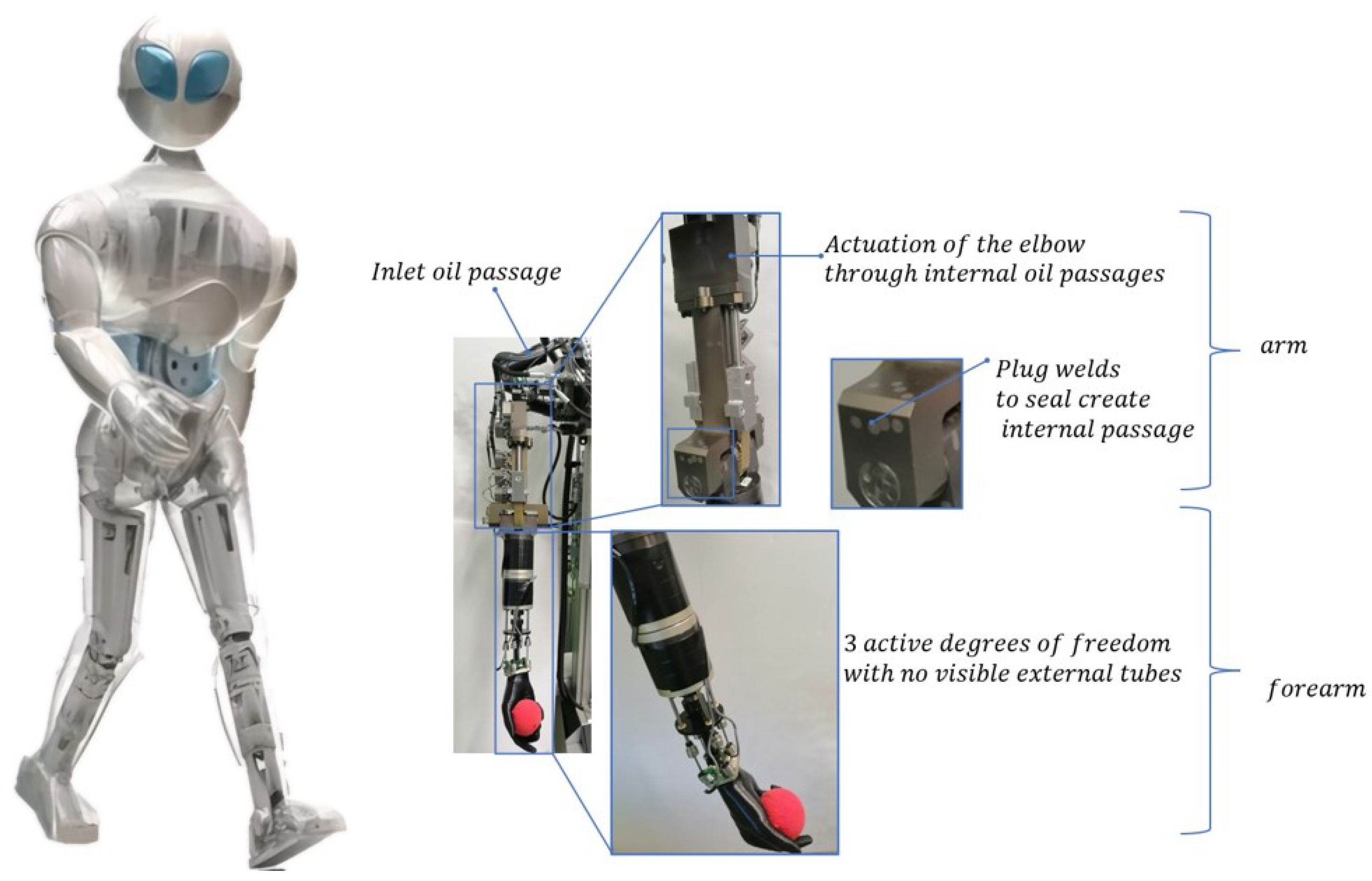
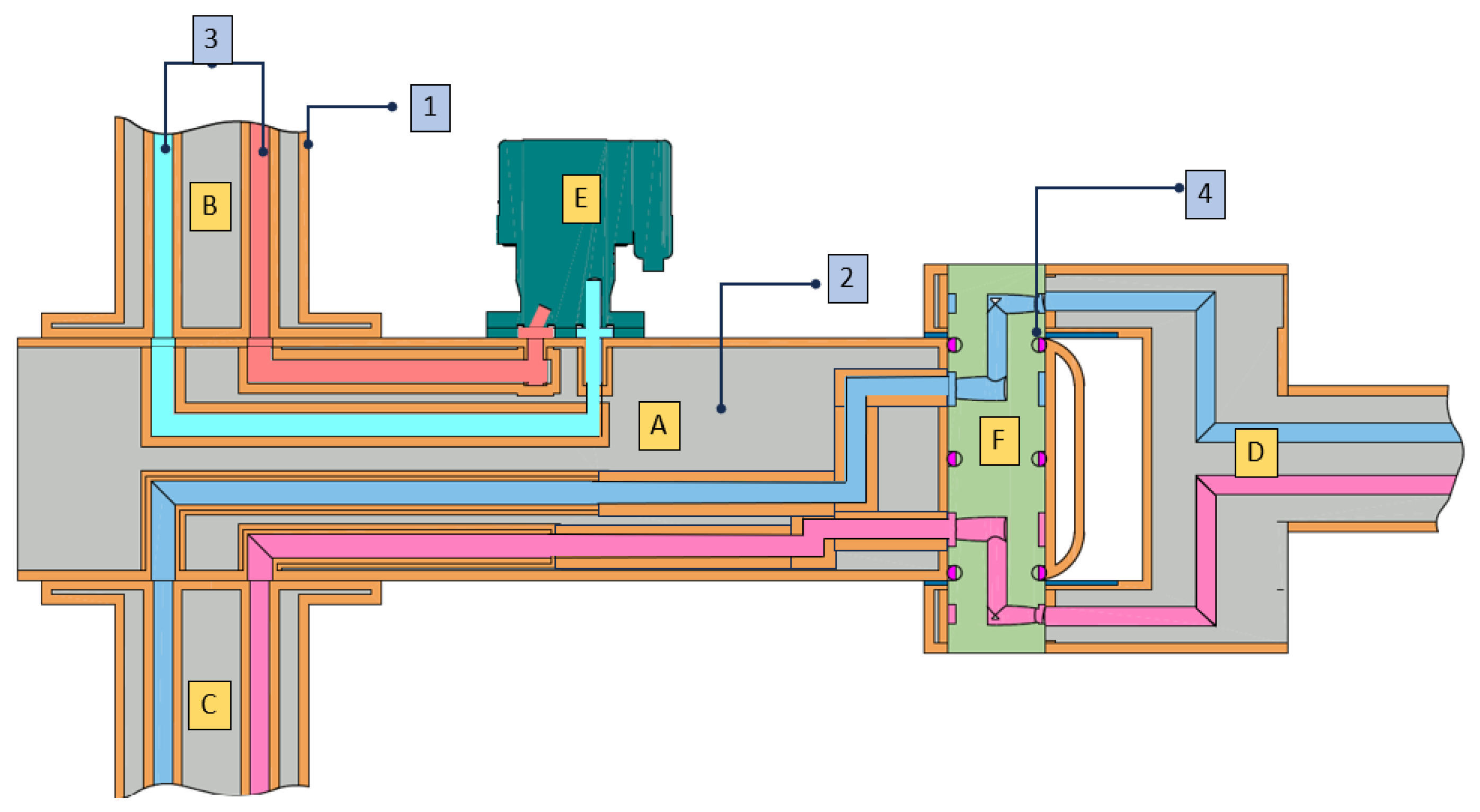
  • Conventional manufacturing: Typically, these processes start with the rough machining of metallic blocks to create external shapes and then oil passages are drilled to form internal oil tubes. This process requires considerable labor, resulting in high machining times and costs. The first generation of HYDROïD—V1 with full hydraulic integration was manufactured using conventional technologies, mainly from steel, titanium, and aluminum. This work became more challenging when hybrid (serial + parallel) mechanisms were involved, which added to the complexity of the integration [7]. As shown in Figure 1, a high-pressure tube fed the robot arm at the shoulder, and the drilled tubes fed the arm and forearm joints internally [8]. The process supplied oil to all 36 hydraulically actuated active joints. Once the manufacturing process was complete, post-processing for corrosion protection or hardening was required, which added cost and time to the initial process. Thus, this manufacturing process is lengthy and costly and adds to the complexity of the design;
  • Metal additive manufacturing: With advances in manufacturing processes and materials, additive manufacturing has emerged as a new approach to designing portable devices. This technology allows the development of intricate shapes in which hydraulic oil passages can be pre-designed and printed within the structure. In 2016, Boston Dynamics announced that the next generation of ATLAS would incorporate structures manufactured with additive manufacturing [9]. The robot leg housed a hydraulic cylinder barrel and valve emplacements. Following the same logic, a smart integrated actuator was developed at IIT, Italy. It was printed with titanium alloys to permit the complex shapes to be made. The all-in-one actuator included integrated hydraulic paths, wire channels, valve emplacements, and position, force, and temperature sensors [10]. However, this technology requires post-processing of the material for stress relief and porosity elimination, which renders it ineffective in terms of cost and time;
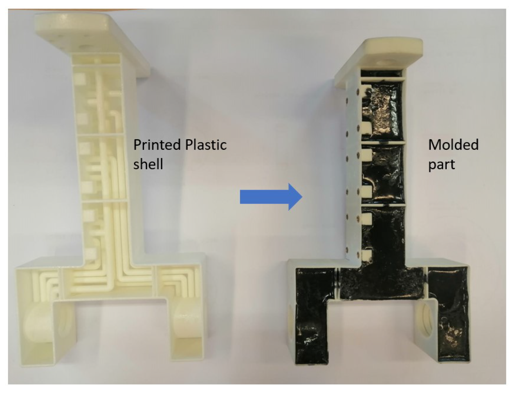
  • Three-Dimensional Pre-Printed Random-Carbon-Fiber-Reinforced Plastic—3D-PPRCFRP: Traditionally, lightweight hydraulically actuated components are manufactured with carbon fiber composite material. Several researchers have worked on developing hydraulic cylinders as an example of a load-bearing part. These components must support high forces due to the exerted pressures. Generally, lightweight hydraulic cylinders are manufactured with a fabric of carbon composite fibers, and epoxy resin is placed on them with the help of a vacuum bag. This methodology only applies to parts with regular geometrical shapes, such as cylinders and plates. Adding to that, fiber-reinforced composites for load-bearing parts entail the need to investigate anisotropy. The fibers’ directions in the layers of the carbon fabric define the part’s capacity to withstand force. Higher strengths are achieved in the direction of the fiber, whereas lower ones are shown in the perpendicular direction.
    In 2018, El Asswad et al. proposed the 3D-PPRCFRP (3D Pre-Printed Random-Carbon-Fiber-Reinforced Plastic) methodology. This method enables the production of integrated hydraulic robotic parts by combining additive manufacturing and carbon composite particles to promote a quasi-isotropic material. The process begins with printing a shell-shaped structural robotic part in plastic with internal passages for oil and electrical wires. The shell-shaped part is then infused with randomly oriented carbon composite particles to increase its ability to withstand high pressures and forces. Figure 2 shows the second generation of HYDROïD’s arm, manufactured using this developed technology, with the printed shell part comprising three layers and a total of 14 internal oil passages. The process led to reducing the weight of the robotic parts by 85 % , significantly reducing manufacturing time and cost [11]. The combination of additive manufacturing and composites resulted in a ground-breaking technology that provides a cost-effective way to produce hydraulically integrated components, overcoming the limitations of previous technologies.
The 3D-PPRCFRP method has the most advantages compared to conventional and additive manufacturing methods. It allows the development of complex-shaped parts through plastic additive manufacturing, while the carbon composite particle material contributes to the lightweight characteristic. This process does not require post-processing, which decreases manufacturing time and cost. For these reasons, the 3D-PPRCFRP is adopted. Carbon-reinforced plastics contribute to the reduction in the weight of mechatronic components. Firstly, lightweight materials improve energy efficiency by reducing the power required to move the device. This has a positive effect on extending the battery life, which increases autonomy. Secondly, lightweight humanoids promote safety; the lighter they are, the easier they are to control, which reflects positively on risk reduction and cost optimization. Despite being lightweight, carbon-reinforced materials are also strong, which can be translated into a high strength-to-weight ratio. Consequently, carbon composite material offers high design flexibility and the capacity to develop complex shapes through molding, optimizing the device’s form and weight. The 3D-PPRCFRP approach holds great promise for developing lightweight hydraulically integrated robotic parts. However, technical challenges are still associated with its implementation. One of the main limitations lies within the molding process. The curing process of the resin undergoes an exothermic reaction to harden. In this phase, voids can be formed in the mixture. Voids weaken the molded structure; therefore, they should be kept minimal. The problem can be solved in prototyping by molding small batches and performing multiple degassing processes in negative pressure chambers.

2. Existing Problems in Hydraulic Integration

As a recently introduced manufacturing technique, the assembly process of components produced with this method is yet to be investigated. Referring to Figure 3, parts A, B, C, and D are manufactured with 3D-PPRCFRP, while part E is a commercially available servo valve. The internal oil passages (3) are made of plastic (1) and reinforced with composite material (2), with more than one passage passing between the parts. A typical mechanism comprises multiple parts that are either statically assembled, such as parts A/B, A/C, and A/E, or dynamically assembled, such as A/F/D. Dynamically assembled parts are leakproof due to hydraulic seals (4), but statically fixed assemblies must withstand the working forces while conserving the leakproof capacity. Challenges arise particularly when integrating off-the-shelf components such as sensors and servo valves (E), which require precise surface finishing to prevent leakage. Consequently, the assembly procedure for the humanoid parts must be easy to perform and maintain, be adaptable for hydraulic application, and have a long service life.
The study of the assembly zone includes various critical factors that should be considered: (i) Material resistance, by which the maximum forces the material can support are identified; (ii) Manufacturing defects and surface finishing. In fact, deviations from the required tolerances can be sources of leak or stress concentrations, leading to fractures; (iii) Temperatures, which can affect the material by causing expansions or retractions, leading to assembly failure; (iv) Aging of the material, which can cause degradation in the long term, especially since these components are exposed to oil and moisture; (v) Leaking at high pressures. Our research aims to develop an assembly methodology for parts manufactured with hydraulically integrated carbon composite material. In doing so, we aim to bridge the gap between hydraulic systems and the capabilities carbon composite materials can offer.

3. Existing Solutions

Several assembly solutions for parts manufactured with composite materials have been envisaged such as direct threading, bonding, and metallic inserts.
  • Direct threading: Direct threading is generally used for metallic component assembly. Several studies were conducted to study the effect of drilling and tapping parameters on the tools and the resulting force in the assembly of composite materials. Freitas et al. [12] studied the effect of tapping parameters, namely, cutting speed and tap coatings, on thread quality. They evaluated the required thrust force and the tapping and tightening torques to drill and tap parts manufactured with composite materials. It was found that coated taps used at a speed of 15 m/min improved thread quality. They allowed a lower tightening torque and thrust. Coated taps reduced the coefficient of friction during the tapping process and protected the tool from wear. This fact was also illustrated by Tsao et al. [13], who found that the thrust force increased significantly with tool wear during the drilling process, causing delamination of the carbon fiber composite material. A failure to adjust tool parameters led to increased wear of the tool and, hence, an inconsistency in the drill sizes and taps. It was concluded that the tool is highly affected by the number of drills made per tool, which negatively influences the dimensions of the hole. Adding to that, due to the wear of the tools, the thread parameters are inconsistent, which reflects an inconsistency in the allowable forces supported by the assembly. This led to additional research to reduce the tool wear and defects such as burr caused in the drilled material by using hybrid composite material, for example, aramid (C-AFRP) [14]. Other studies are working on applying an Artificial Neural Network to predict the adequate machining parameters such as spindle rotation speed and feed rate [15]. Even though direct threading is commonly used in metallic applications, it still has a major drawback when applied to composite materials. In metallic applications, welding and re-tapping can fix a failure in direct threaded assemblies. However, in composite materials, local reparations are not feasible, which requires a replacement of the whole part;
  • Adhesive bonding: Ebnesajjad et al. [16] explored adhesive bonding to assemble parts manufactured with carbon composite materials. This method requires extensive surface preparation and cleaning. It allows for a large stress-bearing area and a uniform distribution of stresses. However, there are drawbacks: (i) Assessing the bond area is impractical since the procedure does not allow for visual examination of the assembled surface; (ii) Extensive surface preparation is required to ensure an adequate bond. In fact, successful bonding is characterized by an adequate choice of adhesive material, the cleanliness of the surface, a good joint design that maximizes the bonding surface without altering the mechanical design, and a curing temperature that should be compatible with the adhesive material; (iii) Long curing times might be needed, with presses to hold the assembly together; otherwise, parts should be placed in autoclaves or ovens to decrease the curing time. These processes are time consuming and costly;
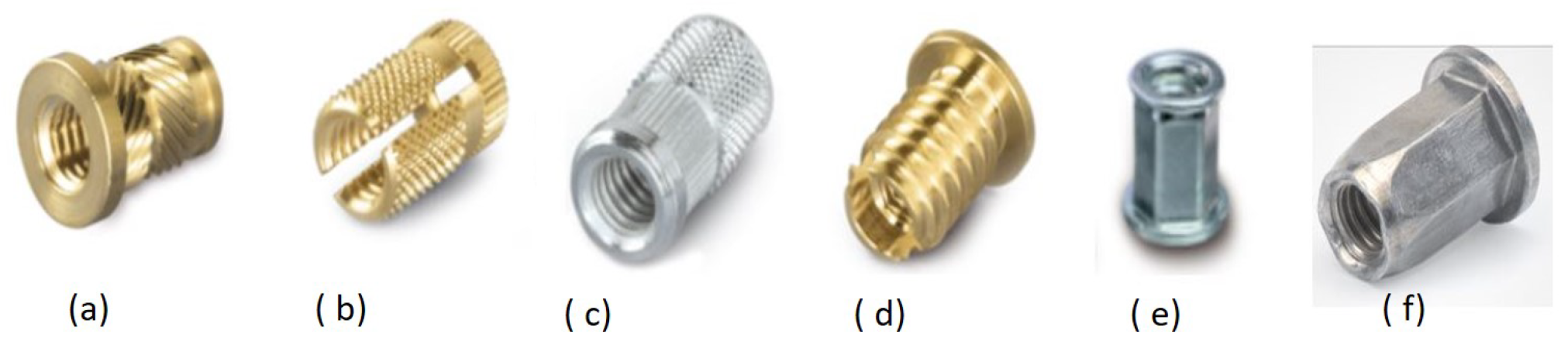
  • Metallic inserts: The metallic thread inserts shown in Figure 4 are suitable for non-permanent assembly solutions. They are mainly used for plastic, wood, or aluminum assembly applications. These inserts have external knurls to grip the material of the part they assemble. Replacing these described inserts will eventually result in permanent deformation of the parts, compromising the interchangeability requirement. Additionally, the external knurls cause irregular deformations that compromise the leak tightness requirement in a hydraulically integrated component.

4. Proposed Solution

Having concluded that the existing solutions do not respond to the assembly requirements, a new solution is proposed in this section. The developed assembly procedure consists of three steps: (i) a local modification in the material characteristics at the assembly place, (ii) an internally threaded intermediate implementation, and (iii) a threaded element to assemble the parts [17]. To comply with the hydraulically actuated humanoid robot assembly mentioned in Section 2, the procedure must acquire the following properties:
  • High strength capacity: During hydraulic system operation, axial forces can cause the assembled parts to separate;
  • Replaceability: The intermediates must not damage the composite material when they are replaced;
  • Leakproof capacity: Hydraulic actuation systems require tightness characteristics. The mechanism’s mounting surface must be flat and smooth; T
  • Light in weight: Robotic mechanisms usually need multiple fasteners for assembly. This increases the assembly time and compromises the system’s lightweight requirements.
The proposed solution is based on elastic expansion of the composite material, press fitting the intermediate in the expansion, and assembling with a threaded element, notably, a screw which creates a suitable technology for hydraulic integrationEPATH. The assembly of parts A and B is explained in Figure 5, where the EPATH solution is applied. First, the expansion process applies to the composite material (1), allowing for the intermediate (C) to be pressed (process 2). Part A is then fixed at the surface of part B (process 3) using the screws (D) (process 4).

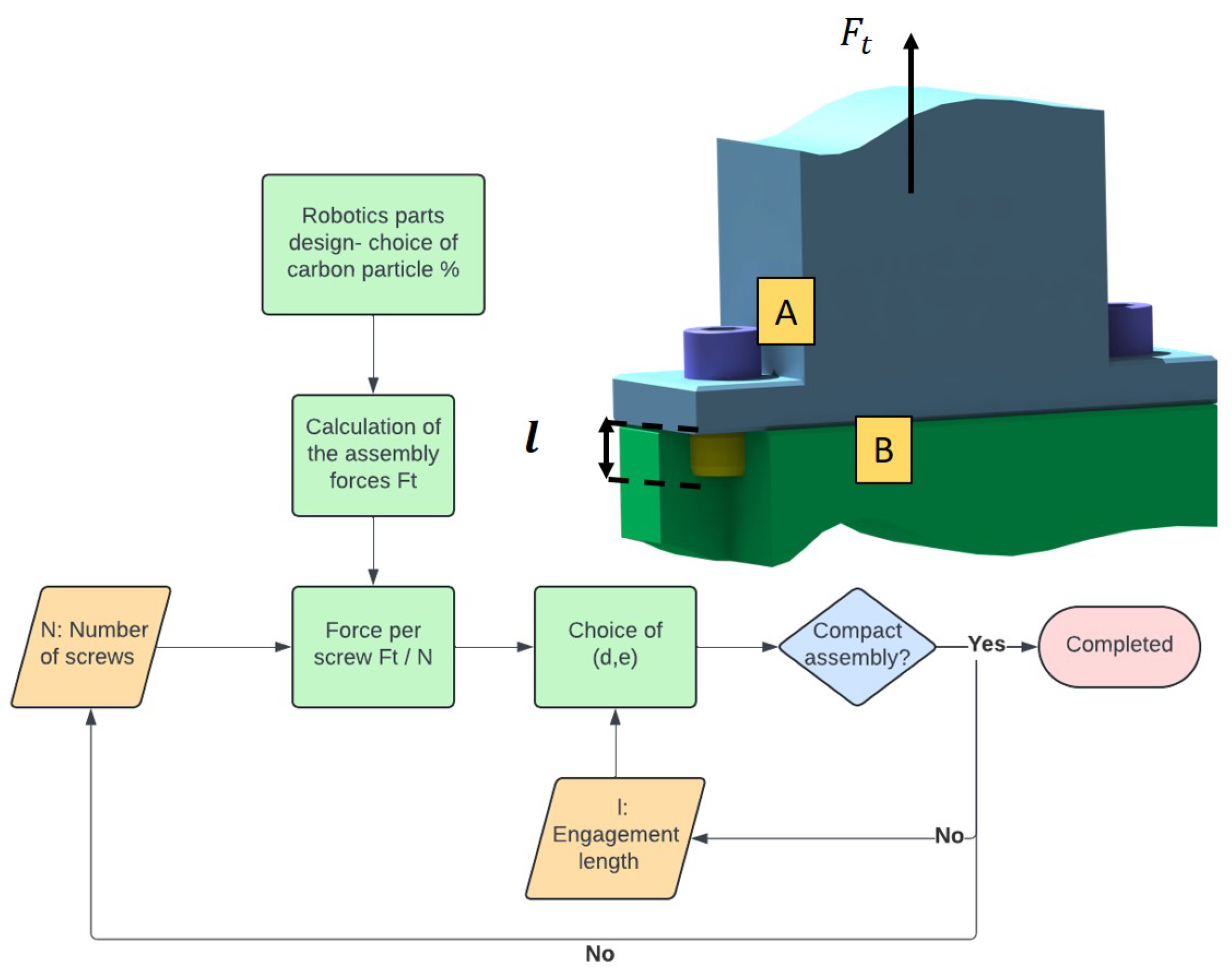
5. Mathematical Modeling of EPATH

The mathematical modeling of the EPATH procedure is crucial. It evaluates the force that holds the assembly zone function of geometric and material-related parameters. This allows for a better comprehension of the system and an evaluation of the parameters involved.

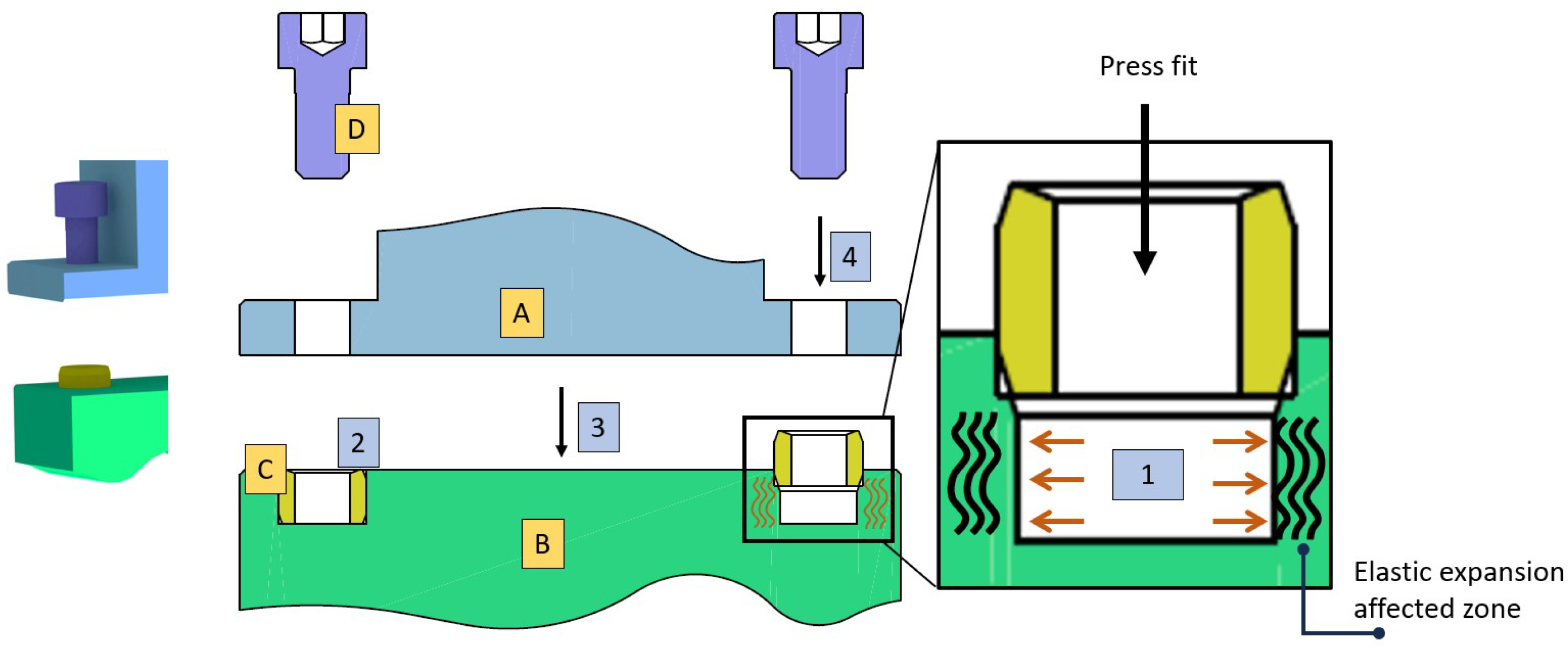
5.1. Concept Description

The EPATH solution utilizes elastic expansion to fit the intermediate inside composite materials. Figure 6 shows a cross-section of an intermediate pressed inside a composite tube. The internal tube’s radius R i 2 is smaller than the external radius of the intermediate R o 1 . This difference in diameters allows the composite material to expand elastically and grip into the intermediate, which increases the resistance to axial forces.
Based on Lamé equations for thick-walled cylinders under pressure, the interference fit assembly is modeled [18]. The intermediate is considered a cylinder under external pressure, and the composite part is a cylinder under internal pressure.
EPATH modeling consists of identifying the maximum axial force that holds the assembly. Several factors affect the value of this force: material resistance, manufacturing defects, surface finishing, temperature effect, aging, and leak prevention. This research article deals with 11 parameters that revolve around material resistance. Consequently, the parameters controlling the model are classified into four categories:
  • Material: The elastic property of the composite material E c o m p plays a significant role in defining its maximum allowable expansion at the interference fit zone;
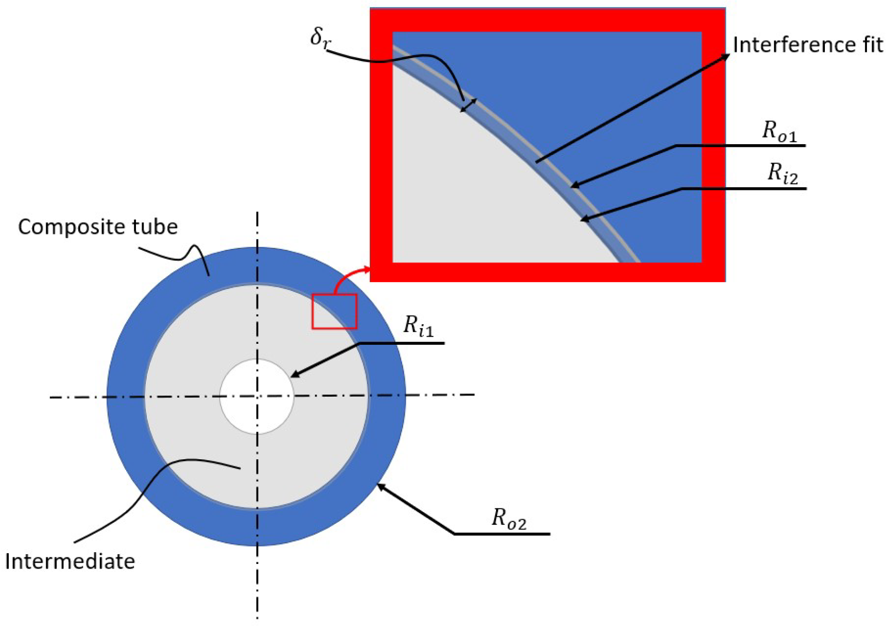
  • Geometric: The model takes into consideration dimensional parameters that include the intermediate’s radii (internal R i 1 and external R o 1 ) as well as the composite material (internal R i 2 and external R o 2 ). They also include the interference fit contact length l;
  • Friction coefficient: The composite material and the intermediate are in full surface-to-surface contact at the interference fit zone. The maximum allowable thrust force is then a function of the friction coefficient μ K between the two materials in contact;
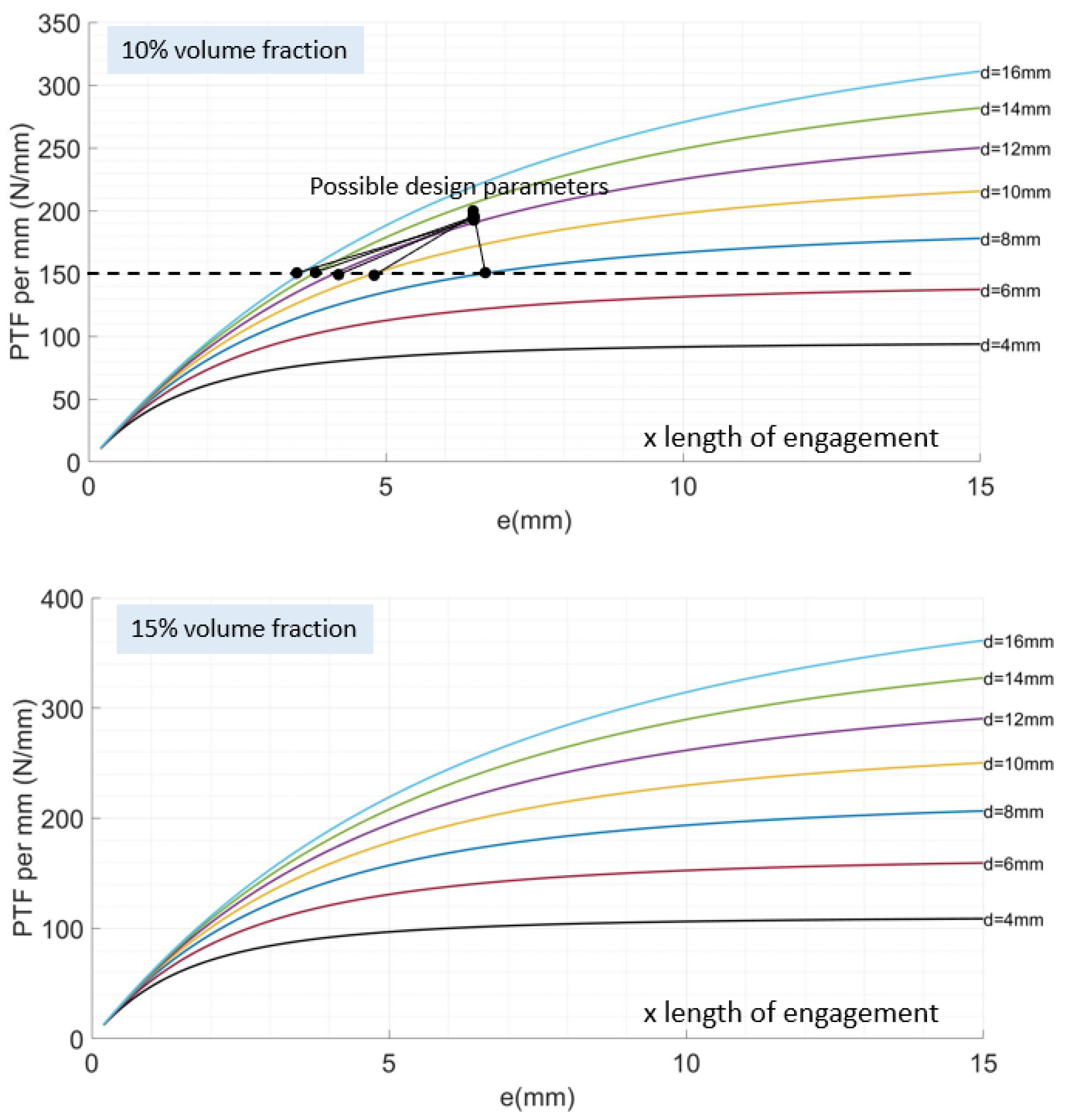
  • Composite material fill rate k: One of the main challenges in the composite molding process is the air bubbles. The high viscosity of the mixture traps the bubbles inside, weakening the structure and decreasing the effective working area.

5.2. Mathematical Model

The radial interference fit is computed as a function of nominal radius R and the hoop strains in the intermediate ϵ t 1 and the composite ϵ t 2 [18] as follows:
δ r = R ( ϵ t 2 ϵ t 1 )
The mathematical model will then start with the development of radial and hoop stresses (Equations (2) and (3)) in thick-walled cylinders calculated through the application of boundary conditions in Lamé’s equations. This permits determination of Lamé’s constants A and B for the intermediate and the composite material [18] as follows:
σ r = A B r 2
σ t = A + B r 2
where r is a variable radius.
R i 1 < r < R 01
R i 2 < r < R 02
At the interference fit radius, once the elastic expansion is accomplished,
R = R o 1 = R i 2
Since both the intermediate and composite hole have open ends, σ z = 0 . Lamé’s constants are now calculated for the intermediate and the composite material considering the following boundary conditions:
Concerning the intermediate: At its internal diameter, the radial stress is null, σ r = 0 , and A 1 B 1 R i 1 2 = 0 ; therefore,
A 1 = B 1 R i 1 2
At the interference fit radius R, the radial stress is equal to the negative pressure, so σ r = P .
A 1 B 1 R 2 = P
By replacing A 1 with its value, we obtain:
A 1 = P R 2 R 2 R i 1 2
B 1 = P R i 1 2 R 2 R 2 R i 1 2
Concerning the composite material: At its outer diameter, no pressure is applied, and σ r = 0 ; therefore,
A 2 = B 2 R o 2 2
At the interference fit radius R, the radial stress is equal to the negative pressure, so σ r = P .
A 2 B 2 R 2 = P
By replacing A 2 with its value, we obtain:
B 2 1 R o 2 2 1 R 2 = P
Therefore,
B 2 = P R o 2 2 R 2 R 2 R o 2 2
A 2 = P R 2 R 2 R o 2 2
When applying Hooke’s law at a plane strain state, the hoop strain at the intermediate is ϵ t 1 = 1 E i σ t 1 υ i σ r 1 .
ϵ t 1 = 1 E i P 1 R i 1 2 R 2 P R i 1 2 1 R 2 R i 1 2 R 2 υ i P 1 R i 1 2 R 2 + P R i 1 2 1 R 2 R i 1 2 R 2
ϵ t 1 = 1 E i P 1 R i 1 2 R 2 1 + R i 1 2 R 2 + υ i P 1 R i 1 2 R 2 1 R i 1 2 R 2
Therefore,
ϵ t 1 = P E i W i + υ i
where
W i = R 2 + R i 1 2 R 2 R i 1 2
ϵ t 2 = 1 E c o m p σ t 2 υ c o m p σ r 2
ϵ t 2 = 1 E c o m p P 1 R o 2 2 R 2 P R o 2 2 1 R 2 R o 2 2 R 2 υ c o m p P 1 R o 2 2 R 2 + P R o 2 2 1 R 2 R o 2 2 R 2
ϵ t 2 = 1 E c o m p P 1 R o 2 2 R 2 1 + R o 2 2 R 2 + υ c o m p P 1 R o 2 2 R 2 1 R o 2 2 R 2
and where the Young’s modulus of the composite material is calculated through the rule of mixture for reinforced composite materials [19] as follows: E c o m p = K f E f ν f + E m ν m , where ν is the volume fraction coefficient, the subscript f refers to the particles, the subscript m refers to the matrix, the volume fraction coefficient of fiber is ν f = 1 ν m , and k f is the particle efficiency parameter. Its value is k f = 1 5 for discontinuous randomly oriented particles in space [19]. Assuming that the material is homogeneous and no porosity is present,
ϵ t 2 = P E c o m p W c o m p + υ c o m p
where
W c o m p = R 2 + R o 2 2 R 2 R o 2 2
By replacing Equations (18) and (23) with Equation (1),we obtain the radial interference fit as follows:
δ r = R P 1 E c o m p W c o m p + υ c o m p + 1 E i W i υ i
The pressure at the interference fit zone is then calculated:
P = δ r R 1 E c o m p W c o m p + υ c o m p + 1 E i W i υ i
The difference between the diameters of the intermediate and the composite material (diameter of the intermediate > diameter of the composite hole) causes the composite material to expand elastically, and pressure is exerted on the external diameter of the intermediate, holding it in position. The pressure is expressed in Equation (26). Axial forces work to remove the intermediate from its position and tend to break the assembly. Knowing that the pressure resulting from the interference fit should overcome every pressure created by the applied force and torques, as shown in Figure 7, we can consider that [20]
P F 2 π R l μ K
where F is the applied axial force and l the length of the intermediate.
The Push Through Force ( P T F ) is then equal to this force.
F = P T F = 2 π R l P μ K
Referring to Equation (28), we can identify 11 variables.
P T F = f ( R , R i 1 , R o 2 , l , E i , E f , E m , ν k , ν f , ν i , ν c o m p )
Each parameter has a different impact on the P T F value. Their effect is studied numerically in the upcoming section.

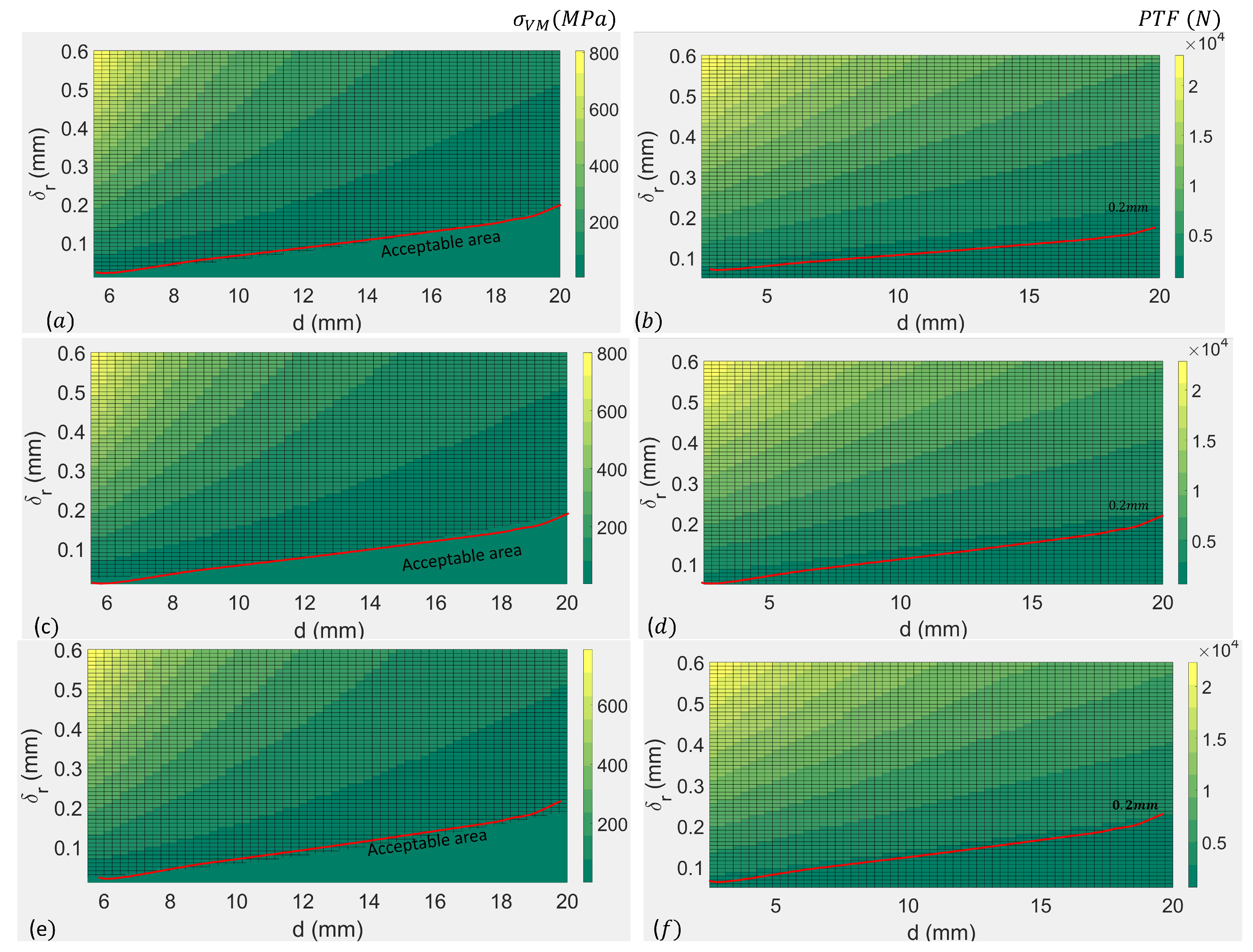
6. Numerical Validation

The numerical validation of the mathematical model in this section was conducted using MATLAB; R2021b. It permitted the identification of the impact of the 11 parameters on the P T F . The evaluation of the real value of Young’s modulus allowed for a more realistic numerical simulation. The composite material properties used in the experimental validation were obtained using specimens according to ISO 527-4 [21]. According to ISO 527-4, specimens of rectangular plastic molds were prepared. The prepared mixture of carbon composite material was then molded inside. When the curing process finished, the specimens were separated from the molds and fixed on a universal testing machine. The rectangular part was fixed on both sides of the machine’s jaw. The upper jaw moves upward. The applied force to move the jaw and the distance allow the calculation the stresses generated in the specimen. The machine’s software generates the Young’s modulus, the strain, and the stress at fracture, which were set as a limit in the numerical simulation of the PTF. The properties of the 10 % carbon composite are given in Table 1.
As shown in Figure 8, a numerical simulation was conducted to determine the effect of the nominal diameter d and the composite thickness e = R o 2 R i 2 on the P T F value that the EPATH assembly can support. The intermediate’s material was steel. For this purpose, the von Mises stresses were calculated to set the maximum stresses that the composite material can support. If the von Mises value is lower than the maximum stress the composite material can support, then the parameters governing the interference fit can be considered acceptable. The acceptable range of P T F is marked inside the red area. It can be noticed that the thickness of the composite e and the nominal diameter d play a major role. It is obvious that, when e increases, P T F increases. Also, at the same nominal diameter, P T F becomes constant after a certain value of e. This allowed for the optimization of the design of the robotic part and avoided over-dimensioning.
The numerical simulation of the von Mises stresses and the Push Through Force for the 10 % volume fraction coefficient of the carbon particle is plotted in ( a , b ) for steel intermediates, in ( c , d ) for brass intermediates, and in ( e , f ) for aluminum intermediates is and shown in Figure 9. The limit line of the admissible von Mises stresses was drawn based on the values of the maximum stresses found in the traction test (Table 1). It can be noticed that the Push Through Force ( P T F ) is higher when the interference fit value ( δ r ) is higher and the nominal diameter (d) is lower. A combination of ( δ r , d ), which creates stresses above the limit line, causes plastic deformation of the composite material or even breaks it. Therefore, the choice of ( δ r , d ) was made from the acceptable area in the graph.

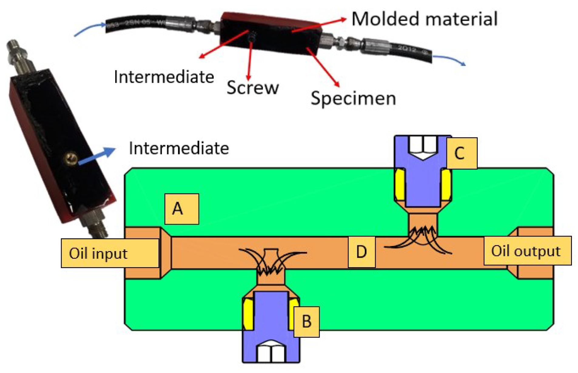
7. Experimental Validation—Leakproof Test

The developed intermediates are destined to assemble two hydraulically integrated parts. Therefore, the intermediates must comply with the leakproof requirement. An experimental validation test was then essential to evaluate the assembly’s capacity to remain leakproof during the functioning of the hydraulic system.
Specimens consisting of plastic cube shells were printed. They were then filled with composite material. The molded part was then drilled for an oil passage. An intermediate was pressed perpendicularly to the surface to receive high pressure from the drilled channel (Figure 10). Pressure was increased progressively until the molded specimen burst. The highest reached pressure was 100 bars. The tested specimens did not show any leak around the intermediates.

8. Experimental Validation—Evaluation of the Push through Force

The required force to push the intermediate from its position, the P T F , were experimentally validated. Specimens of carbon composite tubes with pressed intermediates were prepared. The intermediate was pushed from its emplacement on an MTS universal testing machine. The displacement of the intermediate and the force applied were then registered and plotted.

8.1. Specimen Preparation

The specimen preparation for the P T F validation test included several steps: (i) Tubes 155 mm in length were designed and printed with PLA, as shown in Figure 11a; (ii) Then, randomly oriented carbon composite specimens were molded inside them with a 10 % volume fraction coefficient. The molding procedure was delicate due to the high exothermic curing process, which can cause mold deformation and the creation of air bubbles. Therefore, carbon particles were first mixed in the resin to ensure a full wet-out of the particles. Then, the hardener was added at a 100 30 weight proportion (following the manufacturer’s recommendation [22]). The mixture (resin–carbon particles) was degassed in the degassing chamber to release air bubbles created during the mixing procedure. After adding the hardener, the new mixture was degassed again. The entire mixture of epoxy carbon particles was allowed to cure at room temperature for two days (Figure 11b); (iii) The plastic/composite tubes were machined to create small cylindrical tubes. The internal diameter was made to the tolerance d H7 ( d 0.018 mm for diameters up to 18 mm) (Figure 11c). To create an interference fit, metallic intermediates were manufactured (brass, steel, aluminum) with an external diameter d + 2 δ r (Figure 11d), then pressed inside the composite tubes to create the assembly of the full specimen (Figure 11e). These specimens were used in the P T F test.

8.2. Test Description

The test’s purpose was to apply a force at the top surface of the intermediate to push it from the composite tube. Therefore, new supports were developed for the MTS-100KN universal testing machine, MTS, Singapore (Figure 12). The new upper support has a cylindrical extremity that is applied on the top part of the intermediate to pull it down. It is attached to the moving part of the machine. The lower one serves as a support for the assembly. The upper jaw moves at the speed of 2 mm/s and pushes the intermediate. The displacement and applied force to push the intermediate inside the composite tubes were recorded.

8.3. Test Results

A typical test result is shown in Figure 13. The typical curve starts with a pre-displacement where the intermediate theoretically returns to its position if the applied force is removed. The curve shows the maximum value of the force that forms a landing, recorded as the P T F .
The experimental P T F was registered and compared to the theoretical value calculated through Equation (28). Two zones were identified in the specimen shown in Figure 11b. The specimens that originated from the upper side of the specimen showed a deviation of 20 % between experimental and theoretical data, whereas specimens originating from its lower part had a deviation of up to 27.2 % .
The causes of these deviations are mostly unaccounted parameters in Equation (28) such as surface rugosity, temperature, porosity, and experimental conditions. This article will further investigate the presence of pores in the molded material.

9. Porosity Evaluation and Mathematical Model Enhancement

Porosity is defined as the existence of small voids in the materials. In fact, air bubbles are common and inevitable in composites. Their presence has a negative effect on the mechanical properties. In fact, 1 % air bubble presence in composite materials reduces the tension strength by 3 % , bending strength by 30 % , and impact strength by 8 % [23]. Therefore, each industry defines its own acceptable threshold. In aerospace, for example, the maximum allowable porosity is 2 % [24].
A quantitative analysis of the material porosity was then essential. The density of the composite material was defined as follows:
ρ c o m p = ρ f V f + ρ m V m V f + V m
where V f and V m are the volumes of fiber and matrix, respectively. Due to the presence of porosity, Equation (30) can be rewritten as
ρ c o m p = ρ f V f + ρ m V m V f + V m + V p
where V p is the volume of pores in the material.
Porosity can be assessed using non-destructive or destructive methods. Non-destructive evaluation methods (NDE) include ultrasonic testing, radiography testing, and flash thermography. Ultrasonic testing is commonly used in the industry. It consists of multiple scans of the material in which spherical pores can be evaluated. Pore spheres that have a diameter smaller than the instrument’s resolution cannot be detected [25], which determines its precision. The specimen for X-ray tomography is placed between the X-ray source and the detector on a rotary machine. This method detects defects with a diameter up to 1 μ m [26]. Flash thermography evaluates porosity through thermal diffusivity. This method has recently been combined with infrared cameras that monitor the temperature variation in the material [25]. Destructive evaluation includes density measurement, matrix digestion, and microscopy testing, [27]. Density evaluation consists of a comparison between Archimedes’ theoretical density value and the actual density. This method is complicated as it requires a specific knowledge of the material’s matrix and fiber characteristics and volumes. Another method is matrix burn digestion, which uses acid to break down the matrix and reduce the sample to its fiber content. Microscopy is a visual characterization of the sample with a 2D cross-section analysis. This method is relatively simpler than the above and is widely used.

9.1. Porosity Evaluation in Composite Specimens—Destructive Test

In this paper, a destructive method was deployed. It consisted of a photographic/ microscopic analysis of cross-sections of the specimens to determine the porosity percentage.

9.1.1. Specimen Preparation and Test

The composite tubes used in the P T F evaluation test of Section 8 were fractured. The fractured surfaces were photographed using a Dino-Lite AM-4013MTL digital microscope (Taipei City, Taiwan). A quantitative analysis was then performed on MATLAB (Figure 14). Each specimen was photographed on its longitudinal section. The variation in light reflection on the broken surface caused light areas at the holes and dark areas at flat surfaces, revealing the pores’ presence. Therefore, the photo was first transformed into grayscale. Subsequently, the photo was binarized at the threshold of 0.5 , turning bright areas white and dark areas black. The fill percentage “k” was then introduced as the percentage of black over the number of pixels of the photo.
Referring to Figure 15, zone A represents the top part of the initial molded tube specimen, zone B is the lower part, and zone C is the part fixed to the turning machine when manufacturing the small composite tubes (Figure 11c). Therefore, no specimens were manufactured from zone C. The cross-section of these tubes, enlarged 20.7 times, reveals the presence of pores highlighted in red. It is noticed that a higher concentration of pores is located in zone B, while zone A specimens exhibit fewer pores.
Recalling Equation (24), W c o m p , the denominator of the equation, represents the cross-section of the composite material tube. The presence of porosity reduces this section. Therefore, Equation (24) can be written as a function of the factor “k”.
W c o m p 1 = π ( R 2 + R o 2 2 ) π k ( R 2 R o 2 2 )
Recalling that Equation (26) represents the pressure applied by the interference fit on the intermediate to hold it in place, this equation is then rectified with the correction factor “k”.
P 1 = δ r R 1 E c o m p W c o m p k + υ c o m p + 1 E i W i υ i
Equation (33) shows that the pressure P 1 < P of Equation (26). Knowing that the pressure is proportional to the force P T F , we can fairly conclude that the presence of porosity in the molded composite material will negatively affect the P T F value.

9.1.2. Results Analysis

The evaluation of the specimens’ porosity percentage revealed that the pores’ volume average was 1.2 % for specimens originating from part A and 2.3 % for specimens originating from part B. This is due to the imprisonment of air bubbles at the cylinder tube specimen’s lower part (part B) during the curing process. It is then worth noting that the porosity evaluation revealed a limitation on the feasible molding thickness where the process must be revised for parts with high thickness. Table 2 displays the obtained results, where P T F T represents the theoretical results according to Equation (24), and column P T F C represents the results according to the corrected equation resulting from calculated pressure Equation (33).
It can be noticed that P T F T is always higher than P T F E . This is because the mathematical model did not account for multiple factors including machining defects, surface finishes, temperature effect, and others. It also can be noticed that P T F C is closer to the experimental value than P T F T . This is due to the correction factor “k” introduced to Equation (32). The implementation of Equation (32) in Equation (33) reduces the amount of pressure generated in the interference fit area, hence the allowable P T F value. Specimens T1–T11 were taken from part A and specimens T12–T15 from part B. Knowing that the average porosity percentage is 1.2 % for specimens T1–T11, the correction factor is k = 0.988 . For specimens T12–T15, the average porosity percentage is 2.3 % ; therefore, the correction factor is k = 0.977 . The application of the correction factors resulted in decreases between the experimental data and theoretical value of almost 0.5 % (T1–T11) and 1.8 % (T12–T15).

10. Discussion

The development of the EPATH method provides a solution for hydraulically integrated robotic component assembly. Choosing suitable parameters is depicted in the flowchart of Figure 16. It starts with the robotic part’s design and determining the required volume of carbon particle percentage. Once the parts are designed, the required assembly forces are calculated ( F t ). Then, the force is calculated per screw as F t N , with N representing the number of screws in the assembly zone. The charts are then used to determine the values d , e , l . Figure 17 represents the P T F per 1 mm of engagement length. The charts are designed to compensate for the maximum porosity existing in the composite. Depending upon the mechanical design of the robotic part, a length l is first chosen. Consequently, a pair ( d , e ) can be selected from the graphs. As an example, suppose that total force F t = 4500 N is required at the assembly zone and that N = 6 screws are used. A choice of engagement length of 5 mm means that the intermediate’s length is l = 5 mm. Therefore, the required PTF is calculated as follows:
P T F = F t N l = 4500 6 × 5 = 150 N / mm
Returning to Figure 17, a line is drawn at 150 N/mm. It intersects the curves at five points: ( d ; e ) = ( 16 ; 3 , 55 ) , ( d ; e ) = ( 14 ; 3 , 8 ) , ( d ; e ) = ( 12 ; 4 , 15 ) , ( d ; e ) = ( 10 ; 4 , 85 ) , and ( d ; e ) = ( 8 ; 6 , 7 ) . Depending upon the design geometric limitation, one of the combinations can be chosen, or the calculation can be repeated with an engagement length ( l 1 > l = 5 mm) to further optimize the ( d , e ) parameters.

11. Conclusions

Using carbon composite materials to develop robotic parts has several advantages, particularly weight reduction and design flexibility. This technology allows the integration of external hydraulic tubes inside robotic parts to create oil passages for hydraulically actuated robots. However, managing leaks in assembled surfaces presents a significant challenge when implementing this technology in these robots. This article introduced a novel assembly methodology for hydraulically integrated mechanisms manufactured with carbon composite materials. The developed methodology allows for a robust, lightweight, and leakproof assembly. One of the main advantages of the proposed solution is that it is replaceable, which allows for the easy replacement of defective parts and an easy upgrade. Additionally, the developed solution permits the optimization of the assembly surface, contributing to a compact design. The article detailed the mathematical model of 11 parameters for the assembly zone. A numerical simulation on MATLAB permitted evaluation of the effect of these parameters and the setting of a limitation based on the maximum stress supported by the composite material. Experimental validation was carried out to validate the mathematical model; it allowed the detection of pores inside the molded material. The quantification of this porosity was implemented in a correction factor in the mathematical model, and a maximum deviation of 20 % was observed. The validation of the process for developing lightweight hydraulic cylinders paves the way for their integration into any mechanism requiring lightweight yet load-bearing portable parts. Therefore, future research will include: (i) Optimizing the design parameters to reduce the assembly surface and increase the assembly’s strength. The effect of each parameter will be evaluated to prove its weight on the P T F value. Therefore, a set of optimized parameters can be concluded; (ii) Introduction of additional parameters in the P T F mathematical modeling to include mathematical values that estimate manufacturing defects, surface finishing, temperature effect, aging, and leak prevention. The introduction of these parameters will allow for a realistic P T F evaluation; (iii) Enhancing the manufacturing methodology, which will include optimizing the molding parameters to accelerate the procedure and reduce porosity; (iv) Implementing the manufacturing methodology along with the assembly procedure in developing a lightweight hydraulic cylinder.

Author Contributions

Conceptualization, M.S. and S.A.; methodology, M.S. and K.K.; software, M.S. and A.O.; validation, M.S.; formal analysis, M.S.; investigation, M.S.; resources, M.S. and S.A.; data curation, M.S. and A.O.; writing—original draft preparation, M.S.; writing—review and editing, K.K. and S.A.; visualization, M.S. and A.O.; supervision, K.K. and S.A.; project administration, S.A.; funding acquisition, S.A. All authors have read and agreed to the published version of the manuscript.

Funding

This work was funded by KALYSTA Actuation and the Industrial Excellence Chair between KALYSTA Actuation and the University of Evry.

Data Availability Statement

The raw data supporting the conclusions of this article will be made available by the authors on request.

Conflicts of Interest

The authors declare no conflicts of interest.

Abbreviations

The following abbreviations are used in this manuscript:
SymbolDescriptionUnit
E i Young’s modulus of intermediate’s materialN/m2
E f Young’s modulus of particlesN/m2
E m Young’s modulus of the matrixN/m2
E c o m p Young’s modulus of the composite materialN/m2
ϵ t Hoop strainm/m
ϵ r Radial strainm/m
σ t Hoop stressN/m2
σ r Radial stressN/m2
PExerted pressure at the interference fit areaN/m2
FAxial force applied on the intermediateN
RRadius at the interference fitm
dInterference fit diameterm
R i 1 Intermediate’s internal radiusm
R o 1 Intermediate’s external radiusm
R i 2 Composite tube internal radiusm
R o 2 Composite tube external radiusm
lIntermediate’s lengthm
μ K Friction coefficient between assembled materials
k f Particle efficiency parameter
kFilling percentage of the composite
ν f Particle volume fraction
υ i Poisson ratio of the intermediate’s material
υ c o m p Poisson ratio of the composite material

References

  1. Nelson, G.; Saunders, A.; Playter, R. The PETMAN and Atlas Robots at Boston Dynamics. In Humanoid Robotics: A Reference; Springer: Dordrecht, The Netherlands, 2017; pp. 1–18. [Google Scholar] [CrossRef]
  2. Whitman, E.C. Robust Optimal Walking on the Sarcos Humanoid Robot. Ph.D. Thesis, Carnegie Mellon University, Pittsburgh, PA, USA, 2012. [Google Scholar]
  3. Abdellatif, A.; Alfayad, S.; Hildebrandt, A.C.; Ouezdou, F.B.; Mechbal, N.; Zweiri, Y. Development of a New Hydraulic Ankle for HYDROïD Humanoid Robot. J. Intell. Robot. Syst. Theory Appl. 2018, 92, 293–308. [Google Scholar] [CrossRef]
  4. Alfayad, S.; Ouezdou, F.B.; Namoun, F. Humanoid Robot Implementing a Spherical Hinge with Coupled Actuators. U.S. Patent No 8875594, 4 November 2014. [Google Scholar]
  5. Alfayad, S.; Kardofaki, M.; Sleiman, M.; Arlot, R. Verin a Capteur de Position Integre. Patent WO02023088972A1, 25 May 2023. Available online: https://patents.google.com/patent/WO2023088972A1/en?inventor=samer+alfayad&oq=samer+alfayad&sort=new (accessed on 13 April 2024).
  6. Alfayad, S.; Kardofaki, M.; Sleiman, M. Actionneur Hydraulique à Compensation de Surpression. Patent WO2020173933A1, 3 September 2020. Available online: https://patents.google.com/patent/WO2020173933A1/en?inventor=samer+alfayad&oq=samer+alfayad&sort=new (accessed on 13 April 2024).
  7. Alfayad, S.; Ouezdou, F.B.; Namoun, F.; Bruneau, O.; Henaff, P. Three DOF hybrid mechanism for humanoid robotic application: Modeling, design and realization. In Proceedings of the 2009 IEEE/RSJ International Conference on Intelligent Robots and Systems, St. Louis, MO, USA, 10–15 October 2009; pp. 4955–4961. [Google Scholar]
  8. Alfayad, S.; Tayba, A.M.; Ouezdou, F.B.; Namoun, F. Kinematic synthesis and modeling of a three degrees-of-freedom hybrid mechanism for shoulder and hip modules of humanoid robots. J. Mech. Robot. 2016, 8, 041017. [Google Scholar] [CrossRef]
  9. Dynamics, B. Boston Dynamics’ Marc Raibert on Next-Gen ATLAS: “A Huge Amount of Work” The founder of Boston Dynamics describes how his team built one of the. IEEE Spectrum, 24 February 2016. [Google Scholar]
  10. Barasuol, V.; Villarreal-Magaña, O.A.; Sangiah, D.; Frigerio, M.; Baker, M.; Morgan, R.; Medrano-Cerda, G.A.; Caldwell, D.G.; Semini, C. Highly-integrated hydraulic smart actuators and smart manifolds for high-bandwidth force control. Front. Robot. AI 2018, 5, 51. [Google Scholar] [CrossRef] [PubMed]
  11. El Asswad, M. Nouvelles Méthodologies Pour les Robots Humanoïdes Intégrés Hydrauliques Légers. Ph.D. Thesis, Université Paris-Saclay (ComUE), Paris, France, 2018. [Google Scholar]
  12. de Freitas, S.A.; Vieira, J.T.; Brandão, L.C. Experimental investigation of tapping in CFRP with analysis of torque-tension resistance. Int. J. Adv. Manuf. Technol. 2019, 104, 757–766. [Google Scholar] [CrossRef]
  13. Tsao, C.C.; Hocheng, H. Effect of tool wear on delamination in drilling composite materials. Int. J. Mech. Sci. 2007, 49, 983–988. [Google Scholar] [CrossRef]
  14. Lee, J.H.; Ge, J.C.; Song, J.H. Study on burr formation and tool wear in drilling CFRP and its hybrid composites. Appl. Sci. 2021, 11, 384. [Google Scholar] [CrossRef]
  15. Yenigun, B.; Kilickap, E. Prediction of the tensile load of drilled CFRP by artificial neural network. Appl. Sci. 2018, 8, 549. [Google Scholar] [CrossRef]
  16. Ebnesajjad, S.; Landrock, A.H. Adhesives Technology Handbook; Elsevier: New York, NY, USA, 2014. [Google Scholar]
  17. Sleiman, M. New Actuation Technologies for Humanoid Robotics and Assistive Devices. Ph.D. Thesis, Université Paris-Saclay, Paris, France, 2022. [Google Scholar]
  18. Vullo, V.; Analysis, S. Circular Cylinders and Pressure Vessels Stress Analysis and Design; Springer Series in Solid and Structural Mechanics 3; Springer: Cham, Switzerland, 2014. [Google Scholar]
  19. Callister, W. Materials Science and Engineering: An Introduction; John Wiley & Sons, Inc.: New York, NY, USA, 2007. [Google Scholar] [CrossRef]
  20. Madej, J.; Śliwka, M. Analysis of Interference-Fit Joints. Appl. Sci. 2021, 11, 11428. [Google Scholar] [CrossRef]
  21. ISO 527-4:2023; Plastics—Determination of Tensile Properties. Part 4: Test Conditions for Isotropic and Orthotropic Fibre-Reinforced Plastic Composites. ISO: Geneva, Switzerland, 2023.
  22. Easycomposite. IN2 Epoxy Infusion Resin—Easy Composites. Available online: https://www.easycomposites.co.uk/in2-epoxy-infusion-resin (accessed on 13 April 2024).
  23. Aaboud, B.; Bizet, L.; Saouab, A.; Nawab, Y. Effect of the spatial variation of permeability on air bubble creation and compression. J. Reinf. Plast. Compos. 2020, 39, 285–298. [Google Scholar] [CrossRef]
  24. Shoukroun, D.; Massimi, L.; Endrizzi, M.; Nesbitt, A.; Bate, D.; Fromme, P.; Olivo, A. Quantification of porosity in composite plates using planar X-ray phase contrast imaging. NDT E Int. 2023, 139, 102935. [Google Scholar] [CrossRef]
  25. Meola, C.; Toscano, C. Flash thermography to evaluate porosity in carbon fiber reinforced polymer (CFRPs). Materials 2014, 7, 1483–1501. [Google Scholar] [CrossRef] [PubMed]
  26. Kastner, J.; Plank, B.; Salaberger, D.; Sekelja, J. Defect and porosity determination of fibre reinforced polymers by X-ray computed tomography. In Proceedings of the 2nd International Symposium on NDT in Aerospace, Hamburg, Germany, 22–24 November 2010; pp. 1–12. [Google Scholar]
  27. Little, J.E.; Yuan, X.; Jones, M.I. Characterisation of voids in fibre reinforced composite materials. NDT E Int. 2012, 46, 122–127. [Google Scholar] [CrossRef]
Figure 1. HYDROïD’s arm and forearm-integrated hydraulic tubes manufactured with conventional manufacturing processes.
Applsci 14 04378 g001
Figure 2. HYDROïD’s arm manufactured with 3D-PPRCFRP (El Asswad et al. [11]). The printed shell part has three layers of tubes. It is then molded with carbon composite materials.
Applsci 14 04378 g002
Figure 3. A, B, C, D, and F parts are manufactured with 3D-PPRCFRP; E is a commercial hydraulic valve. A, B, C, and E are fixed statically, while parts A, F, and D are allowed to rotate in relation to each other. 1—plastic shell; 2—composite material; 3—internal oil paths; 4—hydraulic seal.
Applsci 14 04378 g003
Figure 4. Commercial insert types: ultrasonic (a), expansion (b), press in (c), self-tapping (d), molded in (e), and rivet nut (f). Image courtesy: Bollhoff.
Applsci 14 04378 g004
Figure 5. A and B are the parts to be assembled; C: intermediate; D: screw. 1—expanding the composite material; 2—inserting of the intermediate part; 3—assembling the two parts; 4—assembling the screw.
Applsci 14 04378 g005
Figure 6. Parameters in the interference fit assembly: intermediate’s internal radius R i 1 , intermediate’s external radius R o 1 , composite’s internal radius R i 2 , composite’s external radius R o 2 , interference fit radius R.
Applsci 14 04378 g006
Figure 7. Force F and torque T applied on the intermediate. Pressure created at the interference fit is represented by P.
Applsci 14 04378 g007
Figure 8. P T F represented as a function of the nominal diameter d and the thickness of the composite material e for a 10 % volume fraction coefficient and 0.04 mm radial interference fit. The intermediate used for the simulation was made of steel. The acceptable range of P T F is marked inside the red area.
Applsci 14 04378 g008
Figure 9. Acceptable values of the radial interference fit for a 3 mm thickness of composite with ν f = 10 % for steel intermediates (a,b), brass intermediates (c,d), and aluminum intermediates (e,f).
Applsci 14 04378 g009
Figure 10. Leak test: A—tested specimen, B—intermediate, C—screw, D—pressurized oil.
Applsci 14 04378 g010
Figure 11. Steps for specimen preparation—(a) PLA 3D printed hollow tubes used as molds; (b) carbon composite material molded inside PLA tubes; (c) molds turned into small cylinders to host intermediates; (d) intermediates machined at different diameters; (e) intermediates pressed in composite tubes in a press-fit assembly and ready for test.
Applsci 14 04378 g011
Figure 12. Test setup of the push through test. The upper support moves downwards to push the intermediate out from the composite tube. The required force to remove it, as well as the displacement, is registered.
Applsci 14 04378 g012
Figure 13. Result curve of the PTF test: d = 12 mm, e = 4 mm, ν f = 10 % .
Applsci 14 04378 g013
Figure 14. An enlargement of the composite cross-section reveals trapped air in the thickness of the composite material. The photo is grayscaled, and its binarization allows identification of the number of bubbles and their dimensions.
Applsci 14 04378 g014
Figure 15. Typical tube specimen: zone A represents the top zone of the specimen, and zone B is the bottom zone. A cross-section of specimens increased by 20.7 times shows higher porosity in specimens taken from zone B than specimens of zone A.
Applsci 14 04378 g015
Figure 16. EPATH geometric value choice procedure, A and B are two parts assembled with the EPATH solution.
Applsci 14 04378 g016
Figure 17. Geometric parameter design choice graphs.
Applsci 14 04378 g017
Table 1. Carbon composite characterization and traction test results.
CharacteristicValueUnit
ν f 10%
Stress at fracture28MPa
Theoretical Young’s modulus2.6GPa
Experimental Young’s modulus2.66GPa
Young’s modulus deviation2.3%
Strain at fracture0.6%
Table 2. P T F test results.
#Intermediate Material 2 R i 2 (mm) 2 R 02 (mm) 2 R 01 (mm)l
(mm)
PTF E (N) PTF T (N) PTF C (N)
T 1 Steel 8.1 14 8.02 5717 884.8 881.2
T 2 Steel 16.17 24.1 1651475 1482.5 1476.3
T 3 Steel 16.17 241651437 1475.2 1469
T 4 Steel 16.18 24 15.99 51482 1566.5 1559.9
T 5 Steel 12.07 20125604727723
T 6 Steel 12.06 20125593 623.1 620
T 7 Steel 12.2 20 12.05 51305 1548.4 1542
T 8 Brass 8.1 14.07 851100 1110.8 1099.2
T 9 Brass 7.99 14.07 8.15 51130 1223.7 1211
T 10 Aluminum 8.14 14.08 8.06 5741 869.1 865.7
T 11 Aluminum 8.1 14.02 8.06 511281313 1299.5
T 12 Steel 16.15 22.14 165911 1083.7 1060.9
T 13 Steel 16.15 22.12 16.03 5806 860.6 842.5
T 14 Steel 16.22 24.05 16.1 5953 1033.6 1012.2
T 15 Steel 12.1 18 12.04 5416 517.6 507
Disclaimer/Publisher’s Note: The statements, opinions and data contained in all publications are solely those of the individual author(s) and contributor(s) and not of MDPI and/or the editor(s). MDPI and/or the editor(s) disclaim responsibility for any injury to people or property resulting from any ideas, methods, instructions or products referred to in the content.

