Abstract
This paper presents a coaxial counter-rotating planetary transmission system. The transmission system under study is a two-stage planetary gear train (PGT) comprising a fixed-axes PGT and a differential PGT. A dynamic model of the transmission system is established, considering both the excitations caused by the time-varying mesh stiffness (TMS) and the transmission errors, respectively. The Runge–Kutta algorithm is used to calculate and analyze the dynamic characteristics of the system. This includes studying dynamic meshing forces, planet gear displacements, and load-sharing coefficients (LSCs) under both internal and external excitations, as well as different input torques. The results indicate that when considering external excitations, the variations in the meshing force curves become more pronounced. The radial displacements of the planet gears in the differential PGT are greater than that in the fixed-axes PGT. With increasing input torque, the average displacements of the planet gears in all directions tend to increase. The differential PGT, transmitting a higher power, demonstrates a better load-sharing performance compared to the fixed-axes PGT.
1. Introduction
The coaxial counter-rotating planetary transmission system under investigation in this study is a two-stage PGT consisting of a fixed-axes PGT and a differential PGT. Planetary gear transmissions are favored for their high torque density, smooth output, compact design, and high efficiency. The coaxial counter-rotating planetary transmission system brings numerous advantages to the power transmission of helicopter rotor shafts and ship propellers. This type of transmission system enhances transmission efficiency, reduces energy loss, thereby extending equipment operating time, particularly suitable for equipment with long-duration operations, such as with helicopters and ships. Furthermore, the coaxial counter-rotating planetary transmission system, by concentrating power transmission along a single axis, saves space, allowing for more compact equipment design, which is adaptable to the limited space environment in aerospace and maritime sectors. The transmission system provides precise and smooth power transmission, improving the maneuverability and stability of helicopters and ships, particularly evident when operating in complex environments. Due to the typically fewer mechanical connections in coaxial counter-rotating planetary transmission systems, their maintenance costs are relatively low, contributing to reduced operational costs and prolonged equipment lifespan.
The field of PGTs has witnessed substantial enrichment through the noteworthy contributions of numerous scholars dedicated to exploring the dynamic characteristics of these systems. Bahk et al. [1] introduced a computational model to analyze the excitation of teeth profiles following modification. They conducted additional investigations to examine the effects of profile modification on the dynamic response of the system through the utilization of perturbation analysis. Shen et al. [2] introduced a torsional dynamic model specifically designed for planet gears. This model incorporates multiple elements, including gear wear, TMS, unloaded static transmission errors, and gear backlash. By incorporating these elements into the dynamic model, they aimed to provide a more comprehensive understanding of the behavior of planet gears under torsional loads. Xu et al. [3] employed a discretization technique to transform the continuous gear profile into a set of discrete points, which were subsequently utilized for planet gear modeling. Gu et al. [4,5] investigated the trajectories of components and the distribution of loads in planet gears, taking into account eccentricity errors and positional errors. Guo et al. [6] employed real-time excitations in harmonic balance to investigate the dynamics of wind turbine planetary gear sets. Huangfu et al. [7] proposed a continuous-discrete model for helical gears. Based on the dynamics model proposed, they investigated the transmission effects of planet gears, the influence of bolt constraints, and gear vibration. Han et al. [8] presented a three-dimensional load tooth contact analysis (3DLTCA) model considering changes in the center distance and root crack discontinuity of planet gears, and they calculated the dynamic response under the combined effects of assembly errors and crack discontinuities. Wang et al. [9], based on the translational–rotational dynamic model of planetary gear systems, studied the effects of multiple excitations on the vibration response of various planet gear components. Liu et al. [10] coupled the concentrated mass dynamic submodel of sun gears and planet gears with the reduced-order finite element submodel and used this model to analyze the coupled dynamics of flexible planet gears under high-speed and variable-speed conditions.
In the field of multistage compound planet gears and coaxial counter-rotating gears, Liu et al. [11] proposed a dynamic model for the Dual-Planetary Gear System (DPGS) that integrates the dynamic characteristics of the planet bearing rollers and retainers. Fyler et al. [12] proposed a two-dimensional steady-state discrete dynamic model for a dual-stag planetary gear set. They obtained the forced vibration response to gear mesh excitations by applying the modal summation technique. Guo et al. [13] investigated the vibration and acoustic characteristics of a power-split hybrid transmission utilizing a compound planetary gear set through numerical processes and refined dynamics modeling. Tung et al. [14] developed a time-varying reduced-order numerical model for a compound reducer, enabling the prediction of its meshing frequencies and harmonics. Zhang et al. [15] established a translational–torsional concentrated mass dynamic model for a compound planetary gear set, calculating eccentric load coefficients under the influence of excitations such as tooth wear accumulation and transmission errors. Yang et al. [16] proposed a multinode dynamic model for a marine compound gear transmission system, investigating its modal characteristics and dynamic responses. Li et al. [17] developed a dynamic model for a two-stage parallel-axis gear system with variable mesh stiffness, revealing the variations in system vibration under the interaction of coaxial gear ratios and meshing phases. Zhang et al. [18] employed a concentrated mass method to establish a translational–rotational dynamic model for a planetary gear system, analyzing the natural frequencies and mode characteristics of a coaxial counter-rotating helicopter main gearbox. Ryali et al. [19] developed a hybrid planet dynamic load distribution model, employing finite element substructuring techniques to ensure computational efficiency and investigated the influence of planet carrier flexibility on the quasi-static and dynamic responses of planetary gear sets. Lai et al. [20] proposed a flexible–rigid coupling dynamics (FRCD) model for Ravigneaux planetary gear sets (RPGS) with unloaded floating sun gears and studied the influence of the sun gear position on planet dynamic responses, revealing the mechanism of floating ring gear vibration. Wang et al. [21] proposed a novel split-type structure for first- and second-stage gears of planetary reducers. Through rigid body dynamics theory, dynamic simulations, noise tests, and dynamic stability tests were conducted to determine the dynamic characteristics of the entire system. Cui et al. [22], focusing on compound planetary gears, established a bending–torsional coupled dynamic model of the system based on Lagrange’s equations, investigating the bending–torsional coupled meshing deformations and translations and torsions of various engagements. Zhang et al. [23] studied the inherent vibration modes of Ravigneaux compound planetary gear trains (PGT), proposing a two degrees of freedom simplified dynamic model of planet gears considering nonlinearities, such as time-varying mesh stiffness and backlash, and obtaining numerical solutions for the bifurcation and dynamic instability of two groups of planetary gear systems.
In summary, the dynamics models of PGTs are mainly divided into concentrated mass analysis models, finite element analysis models, and rigid–flexible coupling analysis models. In the concentrated mass analysis model, the masses of all components (sun gear, planet gears, ring gear, carrier) in the PGTs are concentrated at single points, and these concentrated mass points are interconnected by springs with stiffness and damping. The finite element model utilizes finite element software to conduct dynamic analysis of gear transmission systems to obtain contact stresses, bending stresses, etc., while the rigid–flexible coupling model is a modeling method that treats components with large deformations as flexible based on the concentrated mass method.
The aforementioned studies on the dynamics of planet gears have mostly focused on single-stage transmissions or simple two-stage serial planetary transmissions with a single input and single output. There has been relatively limited research on coaxial counter-rotating planetary transmission systems composed of fixed-axes PGT and differential PGT. Although finite element analysis models and rigid–flexible coupling analysis models can extract more dynamic information, there are issues such as low efficiency when solving complex systems. Therefore, for complex mechanisms like coaxial counter-rotating planetary transmission systems, employing concentrated mass analysis models can most quickly extract dynamic information that is closer to reality. When using finite element analysis models and rigid–flexible coupling analysis models for calculations, it often takes several hours or even days. However, using the model proposed in this paper for numerical calculations only takes a few minutes. Moreover, when the parameters of the transmission system change, simply replacing the parameters in the program is sufficient, avoiding the complex process of repetitive modeling and grid partitioning required by the finite element method. From the results, which are provided in Section 5 of this paper, through the comparison between ADAMS dynamic simulation and the results of this paper, also proves the correctness of the model.
Therefore, this paper investigates the coaxial counter-rotating planetary transmission system, establishing a dynamic model of the transmission system that considers time-varying mesh stiffness and transmission error excitations. The dynamic characteristics of the system are computed and analyzed using the Runge–Kutta algorithm. This includes studying dynamic meshing forces, planet gear displacements, and load-sharing coefficients (LSCs) under both internal and external excitations, as well as different input torques. The main original findings in this study can be directly employed as preliminary principles for the design of coaxial counter-rotating planetary transmission systems.
2. Composition of the Transmission System
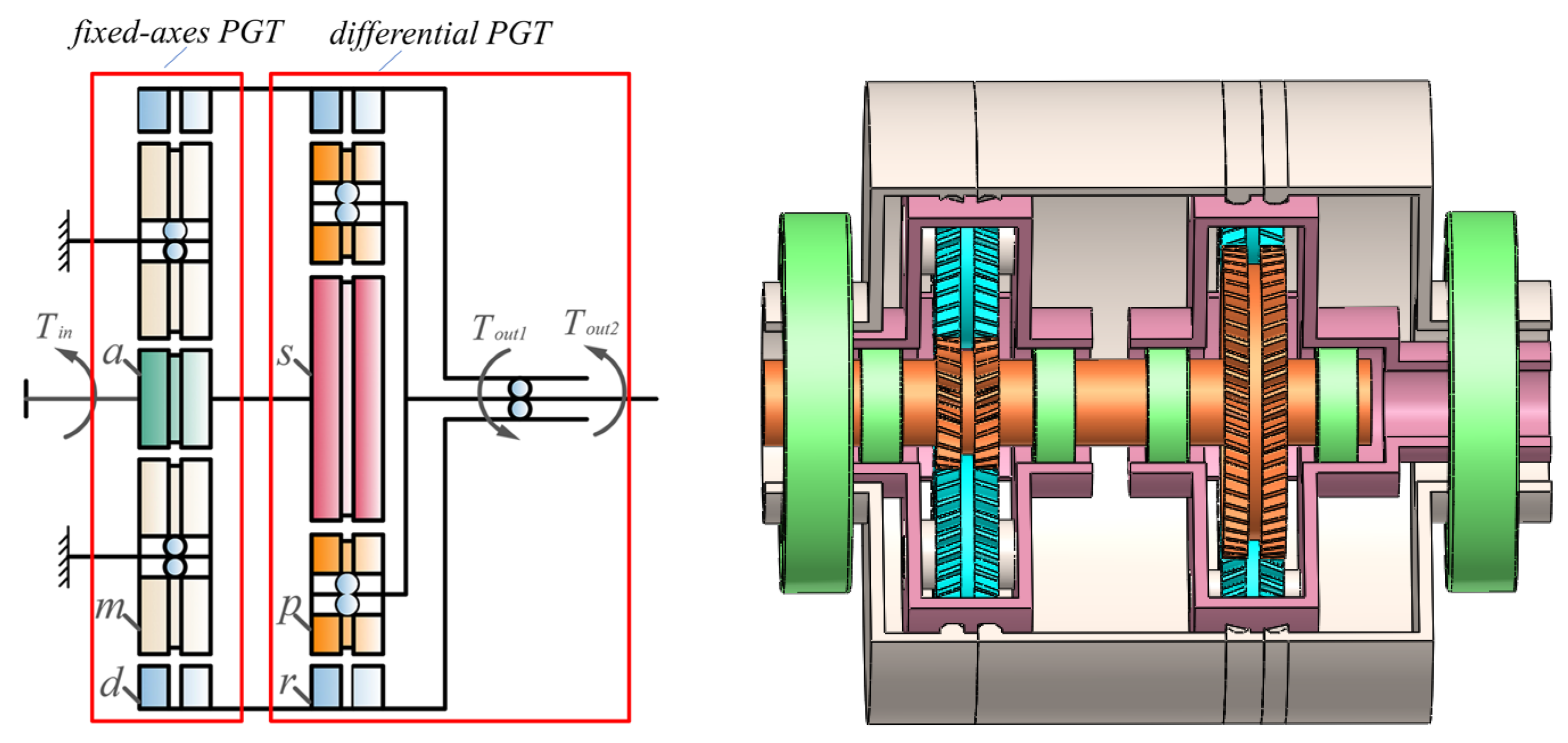
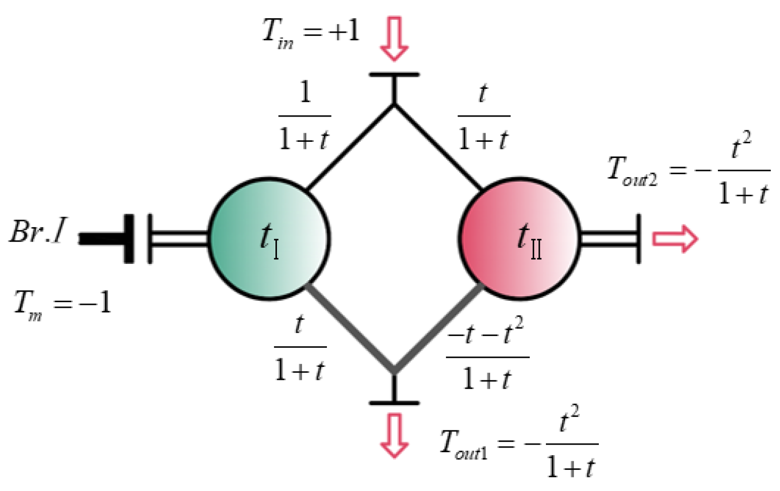
The diagrammatic representation and model of the coaxial counter-rotating planetary transmission system are shown in Figure 1. The entire system is composed of the central components (sun gears—a and s; left ring gears—dL; right ring gears—dR; left ring gears—rL; right ring gears—rR; carriers—c and h; and planet gears—mi and pi), as well as the input shaft and output shaft. This transmission design incorporates a combination of fixed-axes and differential PGTs. The input power is divided into two segments within the system. A specific portion is designated for the fixed-axes PGT, flowing from the sun gear, a, to the ring gear, d. Concurrently, the remaining section is allocated for the differential PGT, starting from the sun gear s and further distributed to the carrier, h, and ring gear, r. The transmission system is represented in the form of the Wolf–Arnaudov symbol [24], as shown in Figure 2. In the figure, tⅠ and tⅡ denote the transmission ratio of the fixed-axes PGT and the differential PGT, respectively, and tⅠ = tⅡ = t.
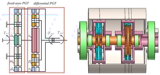
Figure 1.
Diagrammatic representation and model of the coaxial counter-rotating planetary transmission system.
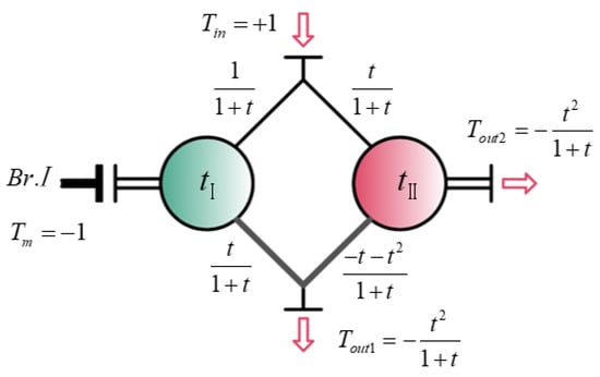
Figure 2.
Diagram of the coaxial counter-rotating planetary transmission system represented by the Wolf–Arnaudov symbol.
3. Dynamic Model of the Transmission System
3.1. Dynamic Model
Taking the example of the differential PGT, the dynamic model, illustrated in Figure 3, is established taking into account parameter excitations, such as TMS, dynamic transmission errors, and support conditions, during the gear meshing process. The fixed-axes PGT follows a similar model, with only different subscripts. Each component in this model has four degrees of freedom. The variables xj, yj, and zj (j = a, m, dL, dR, m1, …, mN, s, h, rL, rR, p1, …, pN) represent the translational displacements of the sun gear, carrier, ring gear, and each planet gear in the x, y, and z directions, respectively. The component torsional displacements around the z-axis are represented by θzj. The symbols k, c, and e in the figure stand for mesh stiffness, mesh damping, and transmission errors, respectively, with distinct components denoted by subscripts. The left and right gears are represented, respectively, by the subscripts L and R. Bearing stiffness is represented by subscripts with b. As an example, kbxs represents the support stiffness of the sun gear, s, in the x-direction. Similarly, kspiL represents the mesh stiffness of the left-side gear pair between the sun gear, s, and the planet gear, p. Likewise, the remaining symbols utilized in the model adhere to the identical notation.
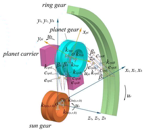
Figure 3.
Dynamic model of the system.
3.2. Calculation of Component Relative Displacements
The generalized coordinate and mass matrix of each component are as follows:
where Mj represents the mass of the component, and Jj represents the moment of inertia with respect to the axis of rotation of the component.
For the purpose of modeling and solving the dynamic model, a fixed coordinate system, o − xyz, is chosen for the fixed-axes PGT, while a follower coordinate system, oh − xhyhzh, is selected for the differential PGT, with the carrier serving as the reference. The displacements and deformations of the components are projected onto meshing lines to obtain the relative displacements among the components.
3.2.1. Relative Displacements between Sun gear and Planet gears
As an illustration, the relationship between the i-th planet gear, p, and the sun gear, s, in the differential PGT, as shown in Figure 4. In the figure, ψpi represents the angular position of the planet gear.
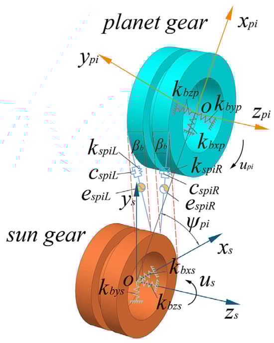
Figure 4.
Relationship between the sun gear and planet gears in the differential PGT.
Along the meshing line, the elastic compression deformation of sun gear, a, and planet gear, mi, can be expressed as positive for compression and negative for tension, as follows:
where j can take on the values of either L or R; ψami represents the angle between the meshing line, ami, and the horizontal axis; αami represents the pressure angle; rba and rbm represent the base circle radius of the sun gear, a, and planet gear, m; βb represents the helix angle; eamij represents the transmission error between the sun gear, a, and planet gear, m; and the superscript sign (±) applies to the left-side gear, while the subscript sign (±) applies to the right-side gear.
The elastic compression deformation of the sun gear s and planet gear, pi, along the meshing line is as follows:
where ψspi represents the angle between the meshing line, spi, and the horizontal axis; αspi represents the pressure angle; rbs and rbp represent the base circle radii of the sun gear, s, and planet gear, p; and espij represents the transmission error between the sun gear, s, and planet gear, p.
3.2.2. Relative Displacements between the Ring gear and Planet Gears
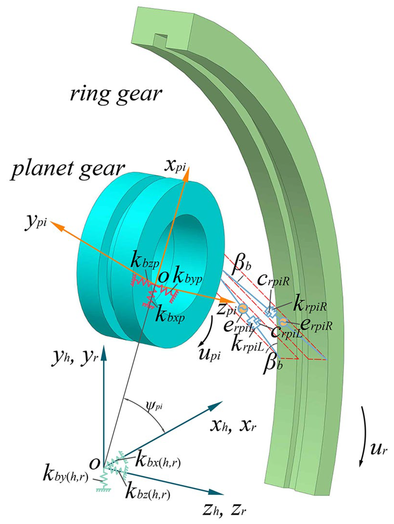
As an illustration, the relationship between the i-th planet gear, p, and the ring gear, r, in the differential PGT is shown in Figure 5.

Figure 5.
Relationship between the ring gear and planet gears in the differential PGT.
The elastic compression deformation of the ring gear, d, and planet gear, mi, along the meshing line is as follows:
where ψdmi represents the angle between the meshing line, dmi, and the horizontal axis; αdmi represents the pressure angle; rbd represents the base radius of the ring gear, d; and edmij represents the transmission error between the ring gear, d, and planet gear, m.
The elastic compression deformation of the ring gear r and planet gear pi along the meshing line is as follows:
where ψrpi represents the angle between the meshing line, rpi, and the horizontal axis; αrpi represents the pressure angle; rbr represents the base circle radius of the ring gear, r; and erpij represents the transmission error between the ring gear, r, and planet gear, p.
3.2.3. Relative Displacements between the Carrier and Planet Gears
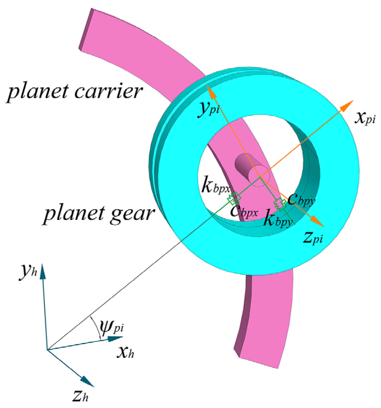
The relationship between the planet gear, p, and the carrier, h, in the differential PGT is shown in Figure 6.
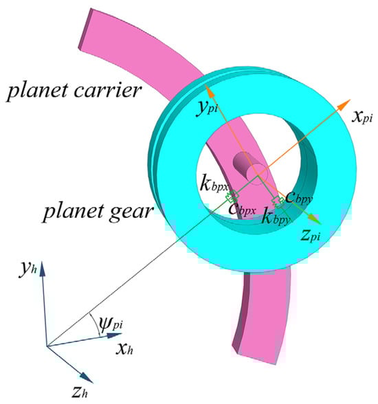
Figure 6.
Relationship between the planet gear and the planet carrier in the differential PGT.
Neglecting the clearance of the bearings, the supporting bearings are approximated by a simplified model using stiffness and damping. Therefore, the relative displacements between the carrier, h, and the planet gear, pi, projected onto the carrier’s coordinate axes xh, yh, and zh are as follows:
where ψpi represents the angle between the xpi axis of the planet gear p and the xh axis of the carrier.
The relative displacements between the carrier, h, and the planet gear, pi, projected onto the planet gear’s coordinate axes xpi, ypi, and zpi are as follows:
3.3. Derivation of the Motion Differential Equations
In the dynamic model, a load torque, Tout1, is applied to the output shaft of the ring gear, rR; a load torque, Tout2, is applied to the output shaft of the carrier, h; and an input torque, Tin, is applied to the sun gear, a. By analyzing the forces acting on each component and employing the Lagrange equations, the motion differential equations for each component, considering the translational motion along the xj, yj, and zj axes and the torsional motion around the zj axis (totaling four degrees of freedom), can be established.
3.3.1. Motion Differential Equation for the Sun Gear, a
The bearing support force acting on the sun gear, a, is as follows:
where kxas, kyas, kzas, and kθzas represent the support stiffnesses of the bearing in the respective directions, and cbxa, cbya, cbza, and cbθza represent the support dampings of the bearing.
The support force of the shaft acting on the sun gear, a, is as follows:
where kxas, kyas, kza, and kθzas represent the support stiffnesses of the shaft in the respective directions, and cxas, cyas, czas, and cθzas represent the support dampings.
The force acting on the sun gear, a, as a result of its mesh with the planet gear, mi, is as follows:
where kamiL and kamiR represent the mesh stiffnesses of the left and right gear pairs between the sun gears, a, and the planet gears, m, respectively; and camiL and camiR represent the mesh dampings.
The motion differential equation for the sun gear, a, is as follows:
3.3.2. Motion Differential Equation for the Planet Gear, mi
The support force of the bearing acting on the planet gear, mi, is as follows:
where kbxm, kbym, kbzm, and kbθzm represent the support stiffnesses of the bearing in the respective directions, and cbxm, cbym, cbzm, and cbθzm represent the support dampings of the bearing.
The meshing force acting on the planet gear, mi, as a result of its mesh with the ring gear, d, is as follows:
where kdmiL and kdmiR represent the mesh stiffnesses of the gear pairs between the left and right ring gears, d, and planet gears, m; and cdmiL and cdmiR represent the mesh dampings.
The motion differential equation for the planet gear, mi, is as follows:
3.3.3. Motion Differential Equation for the Ring Gear, d
The support force of the bearing acting on the left-side ring gear, dL, is as follows:
where kbxdL, kbydL, kbzdL, and kbθzdL represent the support stiffnesses of the bearing in the respective directions, and cbxdL, cbydL, cbzdL, and cbθzdL represent the support dampings of the bearing.
The support force of the shaft acting on the left internal gear, dL, is as follows:
where kxdLdR, kydLdR, kzdLdR, and kθzdLdR represent the support stiffnesses of the shaft in the respective directions, and cxdLdR, cydLdR, czdLdR, and cθzdLdR represent the support dampings.
The motion equation for the left-side ring gear, dL, is as follows:
The support force of the shaft acting on the right-side ring gear, dR, is as follows:
where kxdRrL, kydRrL, kzdRrL, and kθzdRrL represent the support stiffnesses of the shaft in the respective directions, and cxdRrL, cydRrL, czdRrL, and cθzdRrL represent the support dampings.
The motion equation for the right-side ring gear, dR, is as follows:
3.3.4. Motion Differential Equation for the Sun Gear s
The support force of the bearing acting on the sun gear, s, is as follows:
where kbxs, kbys, kbzs, and kbθzs represent the support stiffnesses of the bearing in the respective directions; cbxs, cbys, cbzs, and cbθzs represent the support dampings of the bearing; and wh represents the angular velocity of the carrier h.
The support force of the shaft acting on the sun gear, s, is as follows:
The force acting on the sun gear, s, as a result of its mesh with the planet gear, pi, is as follows:
where kspiL and kspiR represent the mesh stiffnesses of the gear pairs between the left and right sun gears, s, and planet gears, p; and cspiL and cspiR represent the mesh dampings.
The motion differential equation for the sun gear, s, is as follows:
3.3.5. Motion Differential Equation for the Planet Gear pi
The support force of bearing acting on the planet gear pi is as follows:
where kbxp, kbyp, kbzp and kbθzp represent the support stiffness of the bearing in the respective directions, and cbxp, cbyp, cbzp and cbθzp represent the support damping of the bearing.
The force acting on the planet gear pi as a result of its mesh with the ring gear r is as follows:
where krpiL and krpiR represent the mesh stiffnesses of the gear pairs between the left and right ring gears r and planet gears p, and crpiL and crpiR represent the mesh dampings.
The motion differential equation for the planet gear pi is as follows:
3.3.6. Motion Differential Equation for the Ring Gear r
The support force of bearing acting on the left-side ring gear rL is as follows:
where kxrLrR, kyrLrR, kzrLrR and kθzrLrR represent the support stiffnesses of the bearing in the respective directions, and cxrLrR, cyrLrR, czrLrR and cθzrLrR represent the support dampings of the bearing.
The motion equation for the left-side ring gear rL is as follows:
The support force of bearing acting on the right-side ring gear rR is as follows:
where kbxrR, kbyrR, kbzrR, and kbθzrR represent the support stiffnesses of the bearing in the respective directions, and cbxrR, cbyrR, cbzrR, and cbθzrR represent the support dampings of the bearing.
The support force of the shaft acting on the right-side ring gear, rR, is as follows:
The motion equation for the right-side ring gear, rR, is as follows:
3.3.7. Motion Differential Equation for the Carrier, h
The components of the reactive force acting on the carrier, h, from the planet gear, pi, along the carrier coordinate axes is as follows:
The support force of the bearing acting on the carrier, h, is as follows:
where kbxh, kbyh, kbzh, and kbθzh represent the support stiffnesses of the bearing in the respective directions, and cbxh, cbyh, cbzh, and cbθzh represent the support dampings of the bearing.
The motion equation for the carrier, h, is as follows:
Taking the TMS, transmission errors, bearing stiffness, and damping into account, the motion differential equations of each subsystem can be assembled to obtain the overall dynamic motion differential equations of the entire system.
3.4. The Definition of LSC
The LSC in gear systems refers to a coefficient employed for the computation of the forces acting on gears within a gear transmission. Owing to the influence of internal and external excitations, the meshing forces undergo continuous variations. Hence, the introduction of the LSC becomes essential to account for such fluctuations in gear transmissions. The LSCs at a specific temporal instance are to be delineated by bamij, bdmij, bspij, and brpij as follows:
where i = 1, 2, 3; j = L, R.
Take the maximum values of the LSCs of each planet gear at each time point as the LSCs for the internal and external meshing of the planet gears at that moment; then, the dynamic LSCs can be defined as bamj, bdmj, bspj, and brpj as follows:
Take the maximum values of the dynamic LSCs within a period of time as the LSCs as follows:
4. Analysis of Dynamic Response Characteristics of the Transmission System
According to Reference [25], during the gear meshing process, the TMS and mesh damping are calculated. Considering the gear errors with a precision level of 5, transmission system dynamic response characteristics are analyzed using the Runge–Kutta algorithm. The basic parameters are listed in Table 1. The input power of the transmission system was 250 kW, and the input speed was 10,000 rpm.

Table 1.
Parameters of the transmission system.
4.1. Dynamic Meshing Forces
4.1.1. Dynamic Meshing Forces under Rated Condition
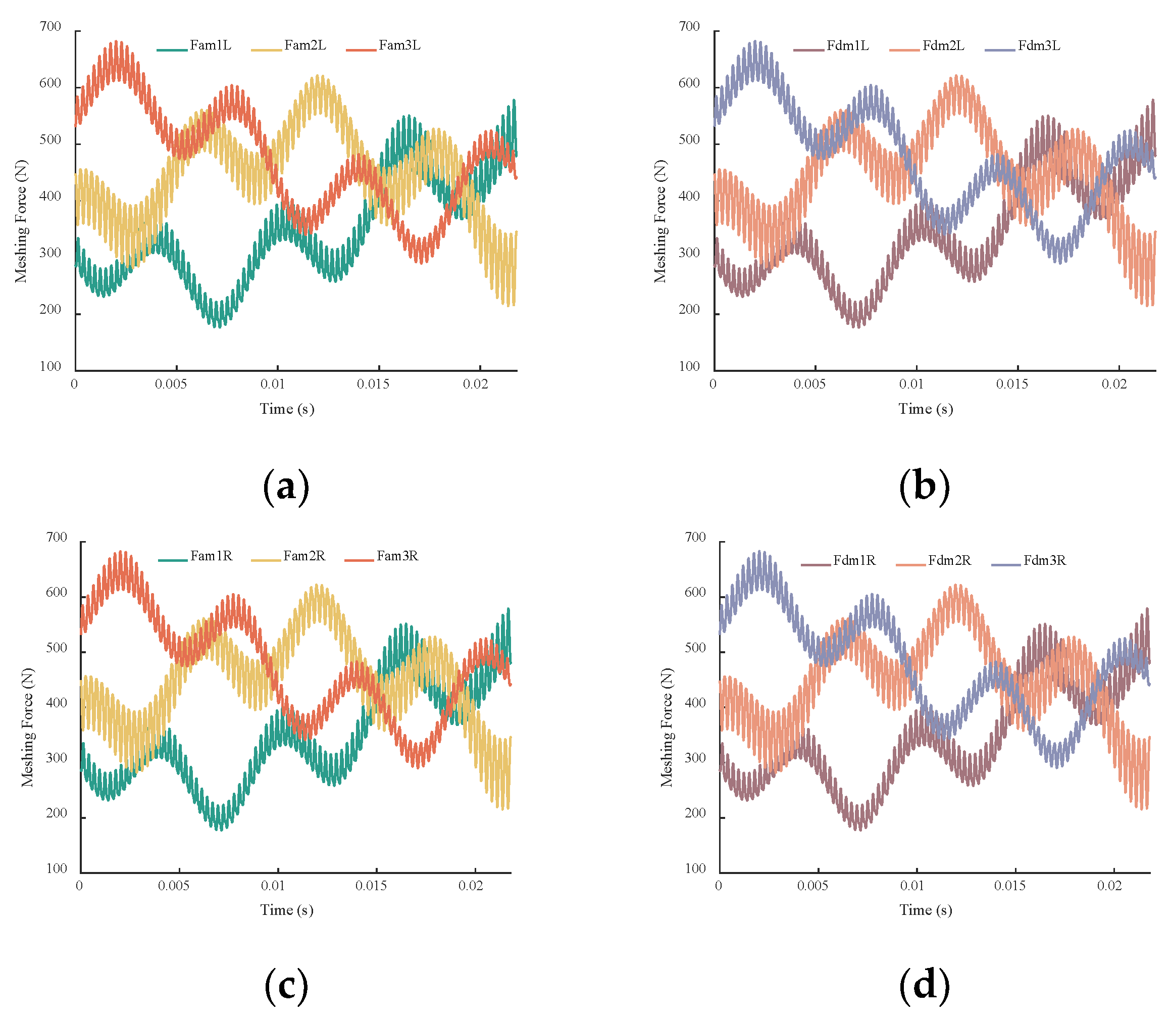
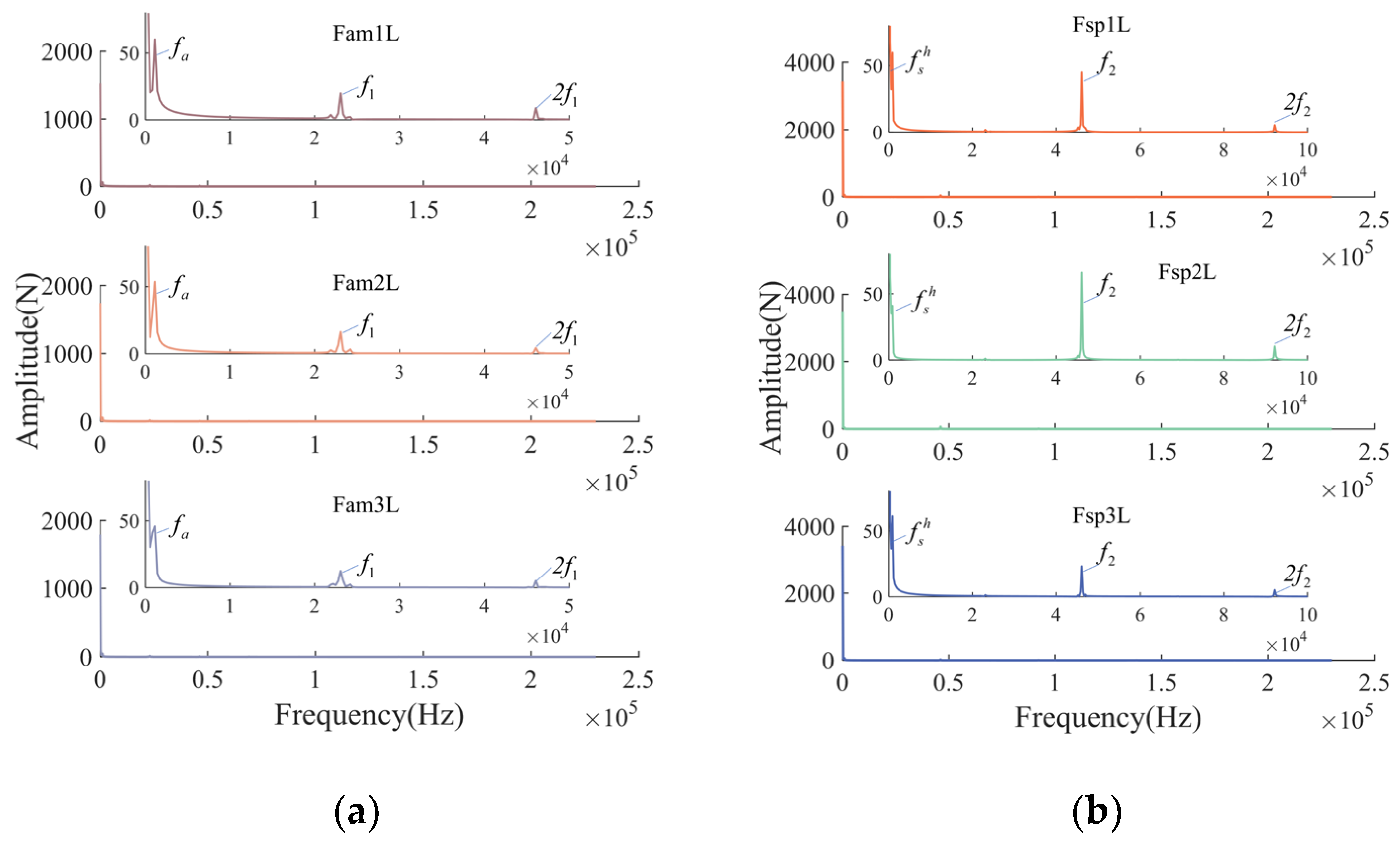
Calculations were performed to determine the time-domain response curves of the dynamic meshing forces for the fixed-axes PGT and the differential PGT on the left and right sides of the pairings. The respective response curves are shown in Figure 7 and Figure 8. As an example, the frequency-domain curves of the dynamic meshing forces for the external meshing pairs of on the left side are given, as shown in Figure 9.

Figure 7.
Time-domain response curves of dynamic meshing forces in the fixed-axes PGT under rated condition: (a) left external meshing pairs; (b) left internal meshing pairs; (c) right external meshing pairs; (d) right internal meshing pairs.
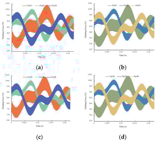
Figure 8.
Time-domain response curves of dynamic meshing forces in the differential PGT under rated condition: (a) left external meshing pairs; (b) left internal meshing pairs; (c) right external meshing pairs; (d) right internal meshing pairs.
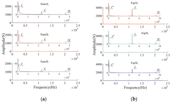
Figure 9.
Frequency-domain curves of the dynamic meshing forces for the transmission system under rated condition: (a) fixed-axes PGT; (b) differential PGT.
On the basis of Figure 7 and Figure 8, it is evident that the dynamic meshing forces in the fixed-axes PGT and the differential PGT exhibited significant similarity. They followed the same temporal trend with only slight differences in magnitude. Therefore, the subsequent analysis exemplifies by the left-side meshing pair of the system. In the fixed-axes PGT, the average values of the meshing forces are approximately 425 N, while in the differential PGT, the average values are approximately 850 N. The meshing forces of each meshing pair fluctuate around their respective average values, and there are differences among them due to geometric relationships and meshing phases.
From Figure 9, it can be observed that due to the constant external load, the maximum amplitude of the meshing forces occurs at the 0 Hz position. In the fixed-axes PGT, the main frequency components are the rotation frequency, fa, of the sun gear, a, and the meshing frequency, f1, of the fixed-axes PGT and its second harmonic, 2f2. In the differential PGT, the main frequency components are the rotational frequency, , of the sun gear and the meshing frequency, f2, of the differential PGT and its second harmonic, 2f2. This is caused by the periodic fluctuations in mesh stiffness and transmission errors.
4.1.2. Effect of External Excitation on Dynamic Meshing Forces
In practical conditions, the transmission system is subjected to complex and varying external loads rather than a single, steady torque. Studying the dynamic response characteristics of the transmission system under varying conditions and load fluctuations helps in comprehending its performance in practical applications when the system is subjected to alternating external loads, as represented by the Fourier series as follows:
where ft1 is w2/3 and ft2 is w2/5.
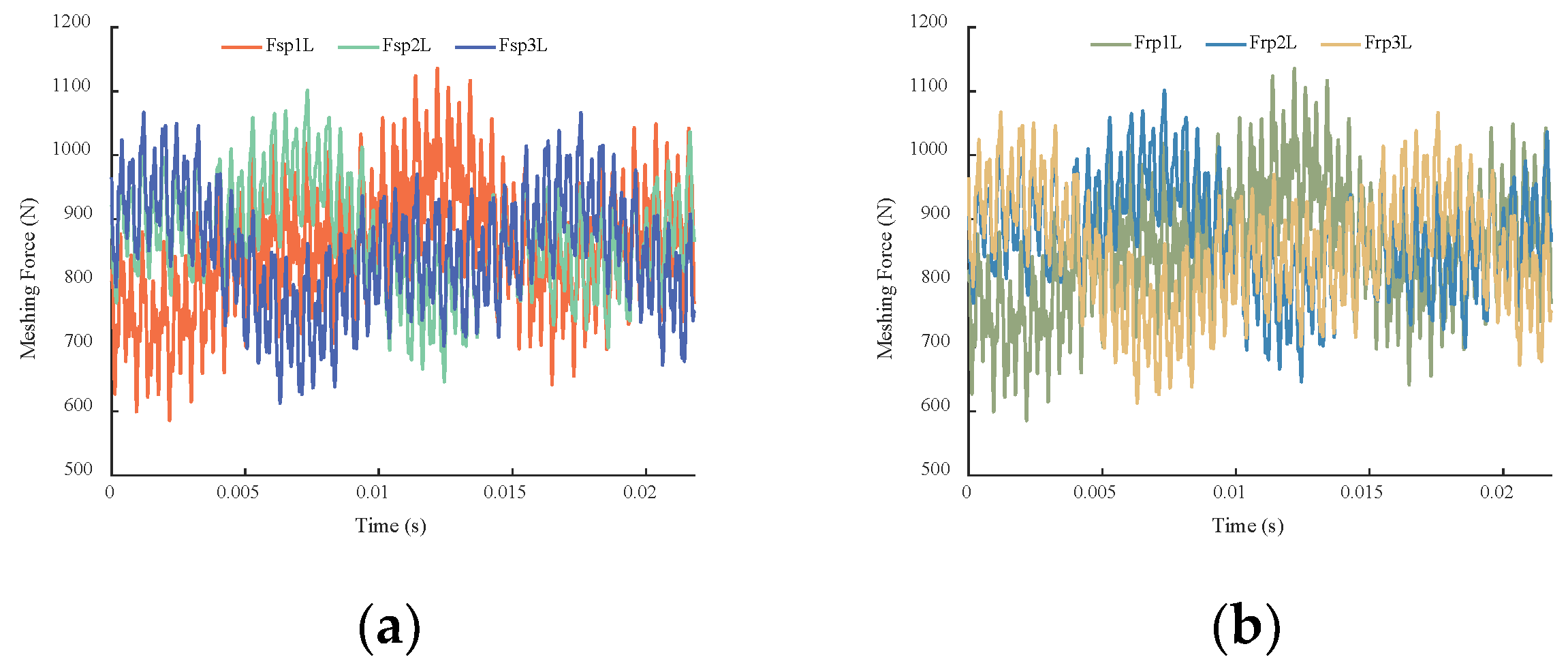
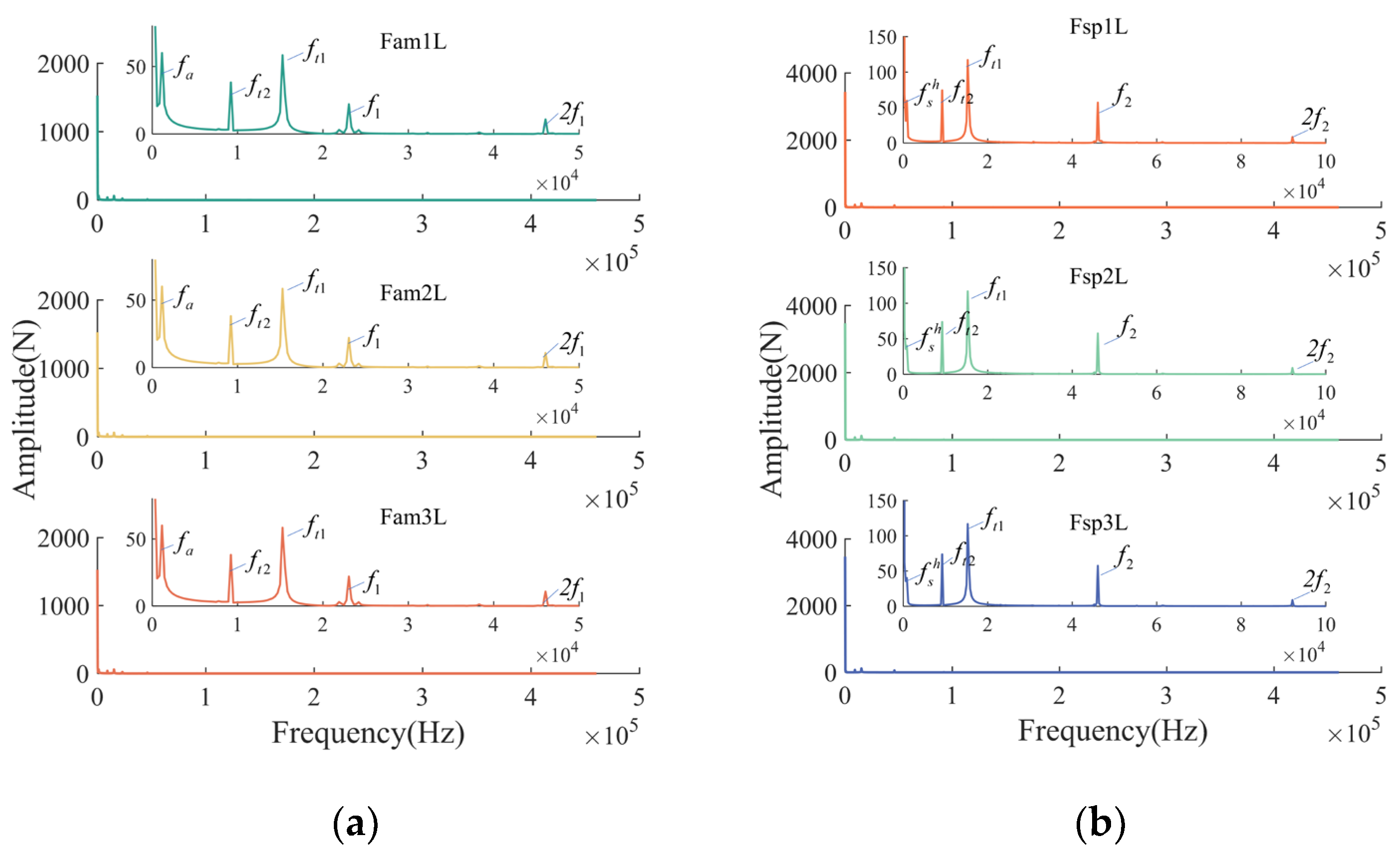
The time-domain response curves of the meshing forces for the fixed-axes PGT and the differential PGT are shown in Figure 10 and Figure 11, respectively. As an example, the frequency-domain curves of the dynamic meshing forces for the external meshing pairs on the left side are given, as shown in Figure 12.
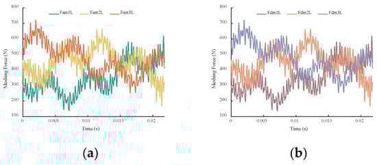
Figure 10.
Time-domain response curves of the dynamic meshing forces in the fixed-axes PGT under external excitation: (a) left external meshing pairs; (b) left internal meshing pairs.

Figure 11.
Time-domain response curves of the dynamic meshing forces in the differential PGT under external excitation: (a) left external meshing pairs; (b) left internal meshing pairs.
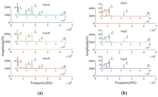
Figure 12.
Frequency-domain curves of the dynamic meshing forces for the transmission system under external excitation: (a) fixed-axes PGT; (b) differential PGT.
In Figure 10 and Figure 11, from the time-domain responses perspective, the overall trends of the dynamic meshing forces considering external loads are consistent with those under rated condition. This similarity is attributed to the variations in TMS and transmission errors. However, there are noticeable differences due to the alternating nature of the external loads. The fluctuation of the meshing forces becomes more prominent, resulting in sharper peaks compared to the meshing forces under the rated condition. The frequent variations in external loads may accelerate fatigue damage on the tooth surfaces. From the frequency-domain responses shown in Figure 12, compared to the frequency-domain response under the rated condition, there are additional frequency components in the spectrum due to the external loads, ft1 and ft2.
4.2. Analysis of Planet Gear Vibration Displacements
The vibration of the planet gears has the potential to change both the internal and external forces involved in the meshing process. Hence, it is imperative to study the vibrational characteristics of the planet gears.
4.2.1. Vibration Displacements of the Planet Gears under Rated Condition
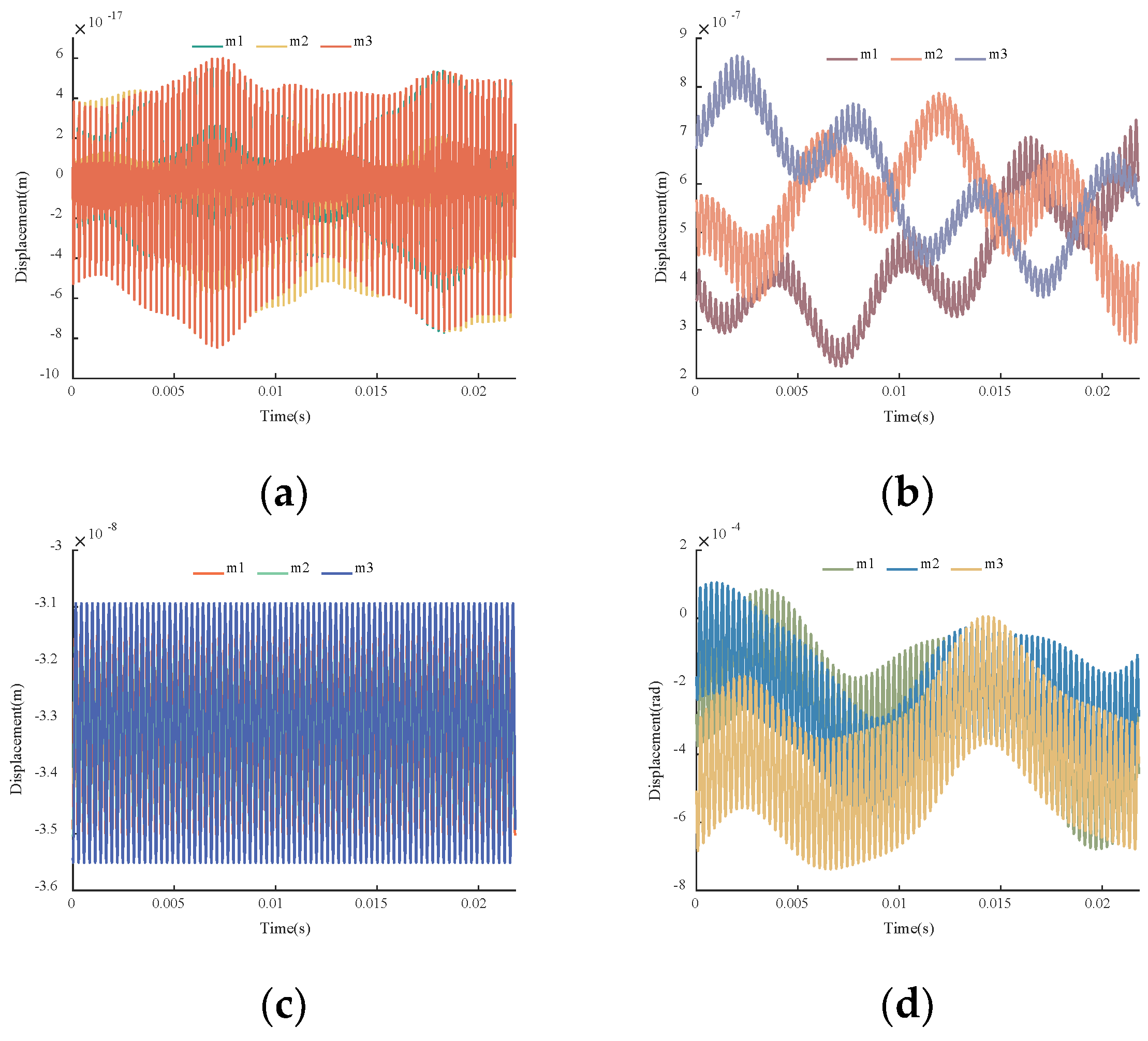
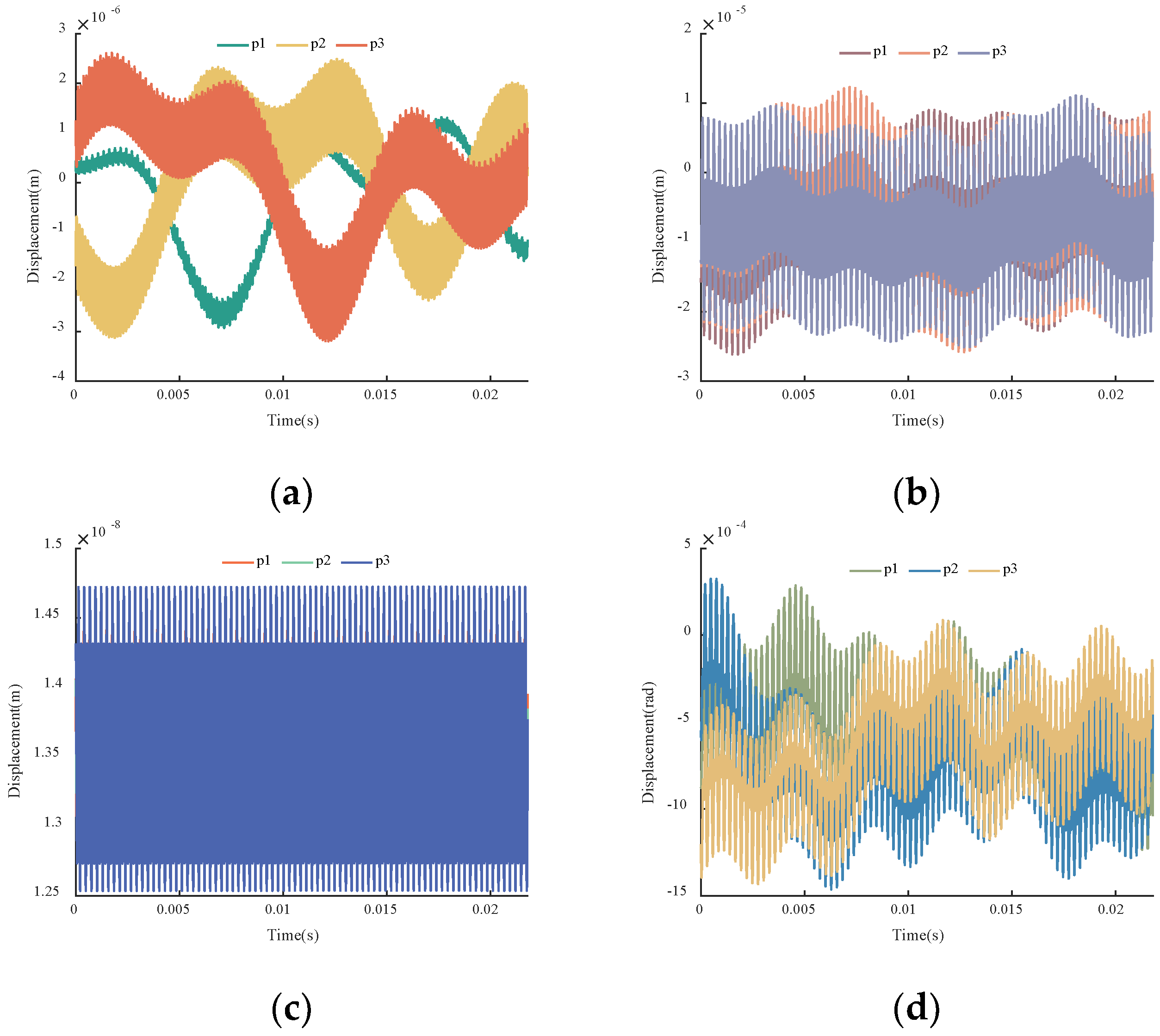
The translational displacements and the torsional displacements of the planet gears are shown in Figure 13 and Figure 14.

Figure 13.
Time-domain responses of the planet gear displacements in the fixed-axes PGT under the rated condition: (a) x-direction; (b) y-direction; (c) z-direction; (d) torsional direction around z-axis.
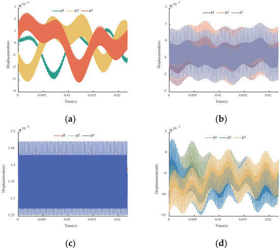
Figure 14.
Time-domain responses of the planet gear displacements in the differential PGT under the rated condition: (a) x-direction; (b) y-direction; (c) z-direction; (d) torsional direction around z-axis.
According to Figure 2, in the fixed-axes PGT, the carrier, c, bears a torque of Tc = −1, while in the differential PGT, the carrier, h, bears a torque of . Thus, in Figure 13 and Figure 14, the radial displacements of the planet gears, m, are less than those of planet gears, p. In the x-direction, internal and external meshing forces cancel one another out, whereas in the y-direction, they superimpose. Additionally, in the differential PGT, there is a driving action on the planet gears, p, along the tangential direction of the carrier, resulting in larger displacements in the y-direction. Along the axial direction, the influence of transmission errors on the meshing forces is relatively small, as the errors primarily affect the radial direction. The primary cause of the axial vibrations is the TMS, with a frequency equal to the meshing frequency. In terms of the torsional direction, the planet gears oscillate around their equilibrium positions with an amplitude on the order of 10−4 rad. The frequency of the torsional vibration is a combination of transmission errors and time-varying meshing stiffness. Because of the geometric relationships and meshing phases differences, the amplitude and variation tendencies of the individual planet gears exhibit discrepancies.
4.2.2. Vibration Displacements of Planet gears under Different Input Torques
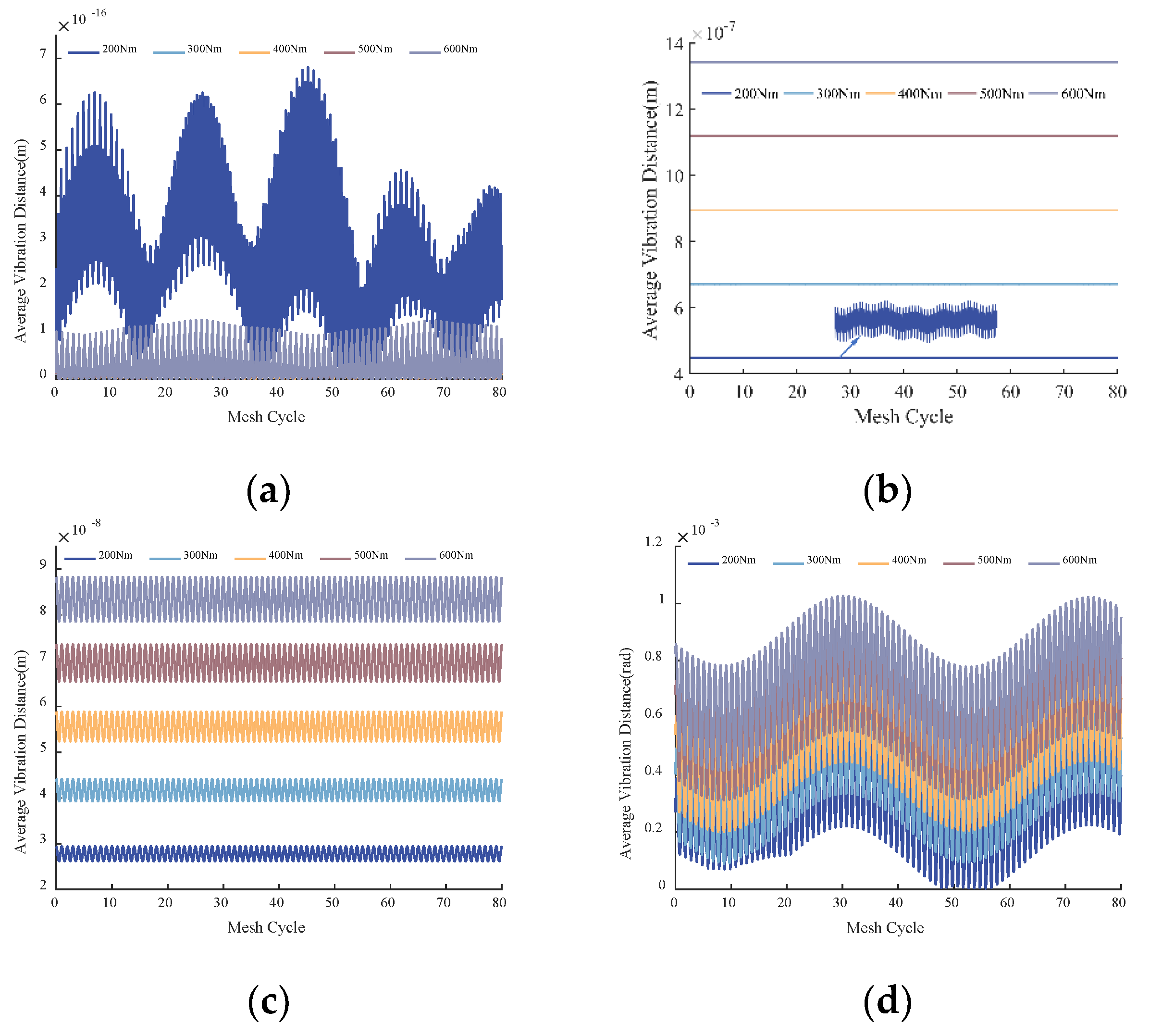
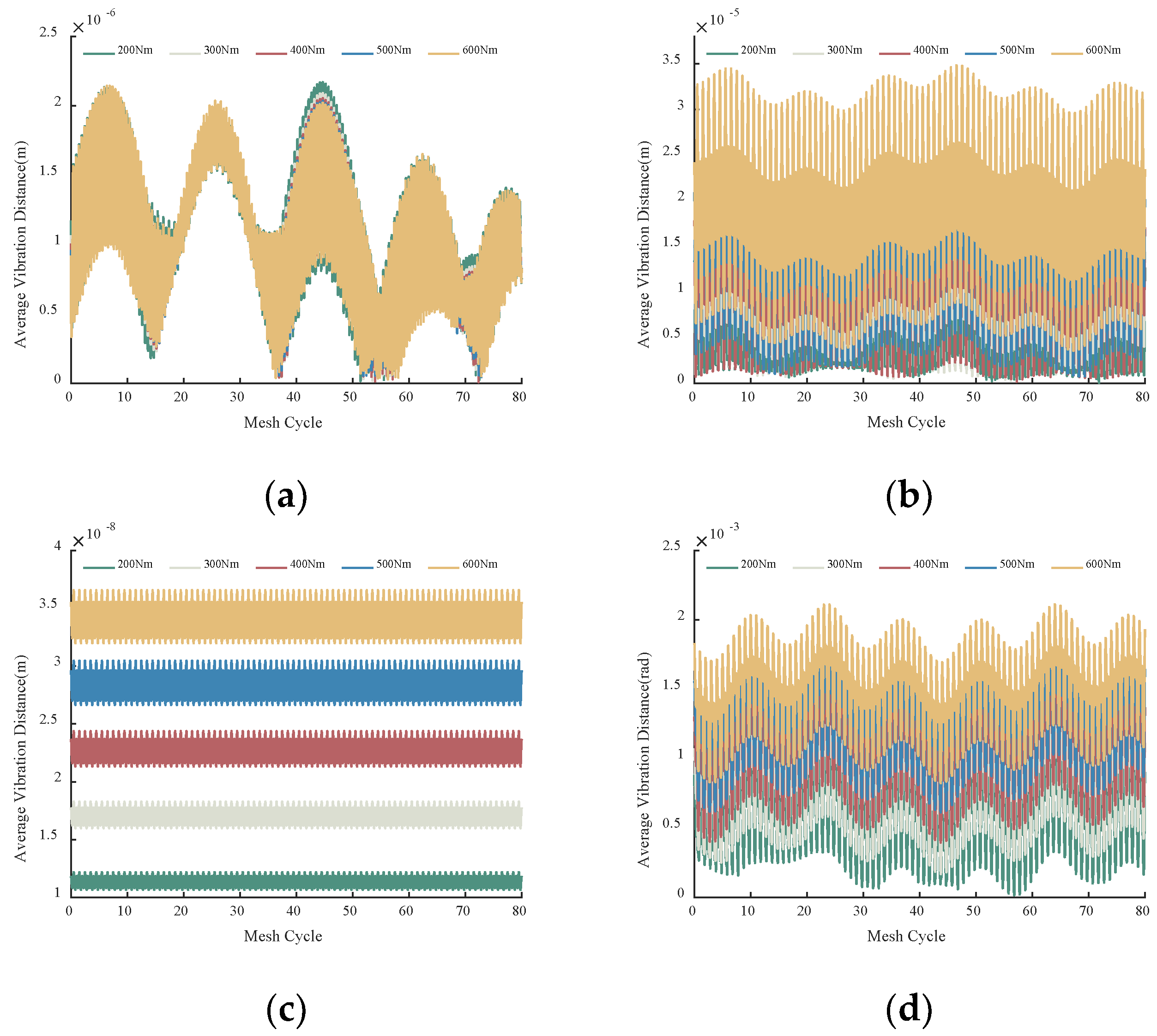
The vibration displacements of the planet gears are subject to variation when there are changes in the input torque. To investigate the vibration displacements of the planet gears in response to varying input torques, five operating conditions were set, as shown in Table 2. For each of the five operating conditions, 80 meshing cycles were selected, and the displacements of the planet gears were analyzed. The time-domain responses are shown in Figure 15 and Figure 16. The peak-to-peak values and variances of the vibration displacements are shown in Figure 17 and Figure 18, respectively.
Table 2.
Five different operating conditions.
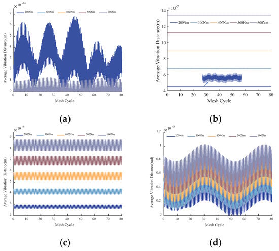
Figure 15.
Time-domain responses of the planet gear displacements in the fixed-axes PGT under the different input torques: (a) x-direction; (b) y-direction; (c) z-direction; (d) torsional direction around z-axis.

Figure 16.
Time-domain responses of the planet gear displacements in the differential PGT under the different input torques: (a) x-direction; (b) y-direction; (c) z-direction; (d) torsional direction around z-axis.
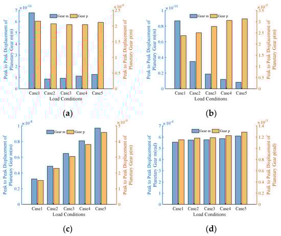
Figure 17.
Peak-to-peak displacements of the planet gears under the different input torques: (a) x-direction; (b) y-direction; (c) z-direction; (d) torsional direction around z-axis.
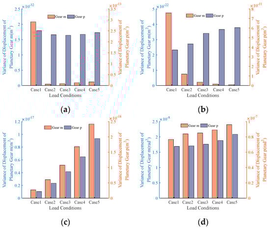
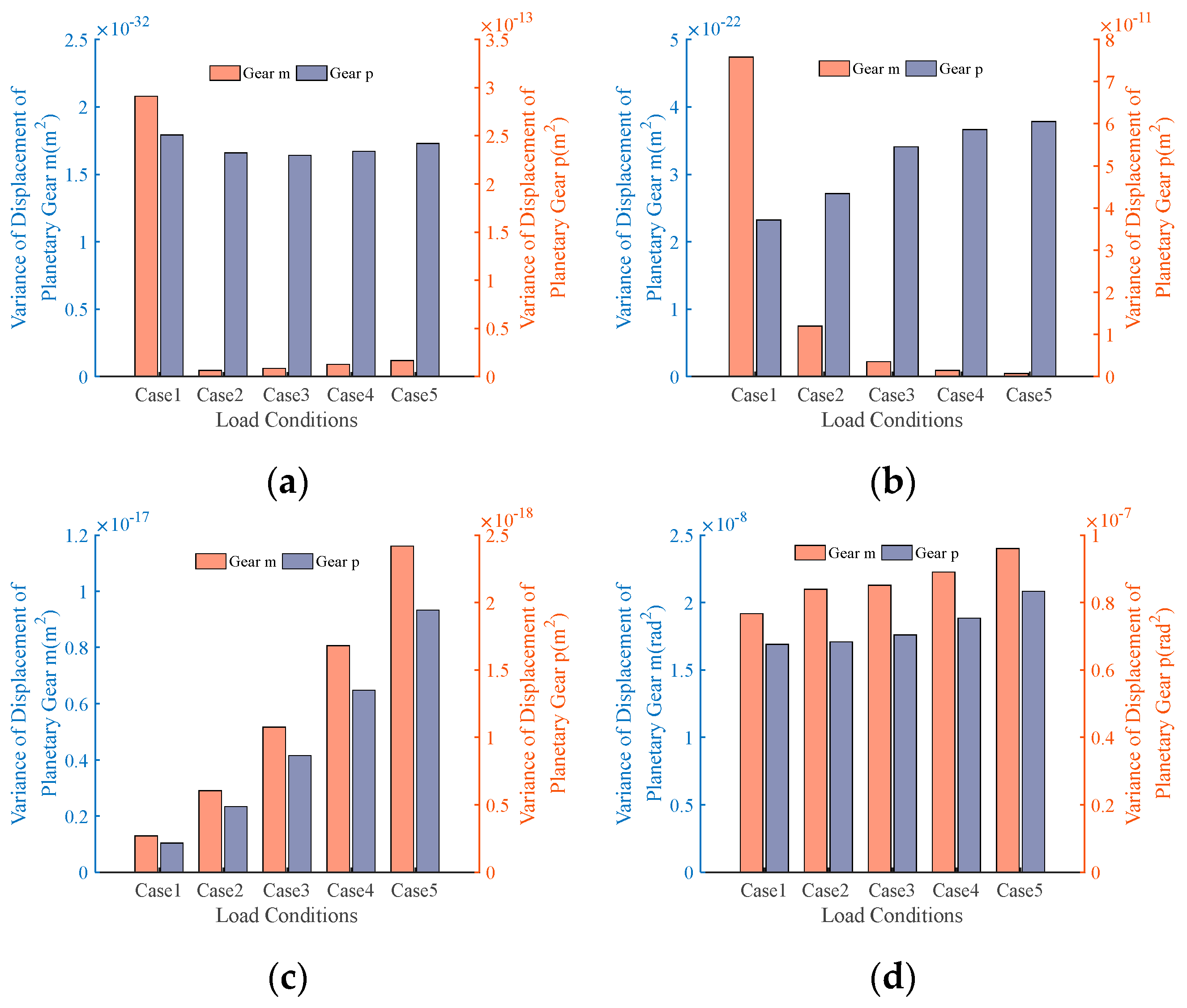
Figure 18.
Variances of the planet gear displacements under the different input torques: (a) x-direction; (b) y-direction; (c) z-direction; (d) torsional direction around z-axis.
From Figure 15 and Figure 16, it is observable that as the torque increases, except in the x-direction, the average displacements of the planet gears in various directions basically tended to increase. The displacements of the planet gears, m, in the x-direction are characterized by their distinctiveness due to their exceptionally small magnitude. Under the five operating conditions, the maximum magnitude remained at around 10−16 m. Therefore, even slight variations in parameters can lead to noticeable changes in its displacement. However, because of its small amplitude, this vibration can be practically negligible. Figure 17 and Figure 18 demonstrate that the peak-to-peak displacements and variances in the planet gears exhibited no discernible patterns in the x-direction. The peak-to-peak displacements and variances in the planet gear, m, in the y-direction exhibited a decrease as the torque increased, suggesting a reduction in the vibration amplitude. Conversely, the trend was opposite for the planet gear, p. In the axial and torsional directions, both the peak-to-peak displacements and variances in the planet gears, m and p, increased with increasing torque, indicating that the vibration became more pronounced in these directions as the torque increased.
4.3. Load-Sharing Coefficients
Using the previously described method in Section 3.4, the dynamic meshing forces of the transmission system were utilized to calculate the LSCs based on the analysis of the dynamic response.
4.3.1. LSCs under Rated Condition
Taking the dynamic LSCs on the left side as an example, the variation curves of the LSCs in the fixed-axes PGT and the differential PGT under the rated condition are shown in Figure 19 and Figure 20, respectively.
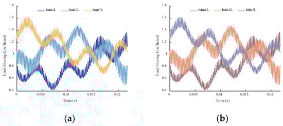
Figure 19.
Variations in the dynamic LSCs in the fixed-axes PGT under the rated condition: (a) left external meshing pairs; (b) left internal meshing pairs.

Figure 20.
Variations in the dynamic LSCs in the differential PGT under the rated condition: (a) left external meshing pairs; (b) left internal meshing pairs.
From Figure 19 and Figure 20, it can be observed that the variations in the LSCs and the meshing forces were generally consistent, fluctuating at around 1. The fluctuation range for the fixed-axes PGT was between 0.4 and 1.6, while for the differential PGT it is between 0.75 and 1.25. Because of the influence of the geometric relationships and mesh phases, there are differences in the LSCs among the meshing pairs. Since the fixed-axes PGT transmits lower torque compared to the differential PGT, the smaller meshing forces were more susceptible to fluctuations caused by errors. As a result, the fixed-axes PGT exhibited larger fluctuations in the LSCs compared to the differential PGT.
4.3.2. Dynamic LSCs under External Excitation
When subjected to external excitation, taking the dynamic LSCs on the left side as an example, the variations in the LSCs in the fixed-axes PGT and the differential PGT are shown in Figure 21 and Figure 22, respectively. The comparative analysis of the dynamic LSCs considering the impact of external excitation versus the absence of external excitation is shown in Figure 23.
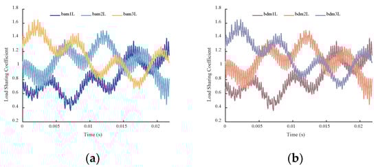
Figure 21.
Variations in dynamic LSCs in the fixed-axes PGT under external excitation. (a) Left external meshing pairs; (b) Left internal meshing pairs.
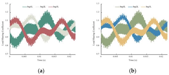
Figure 22.
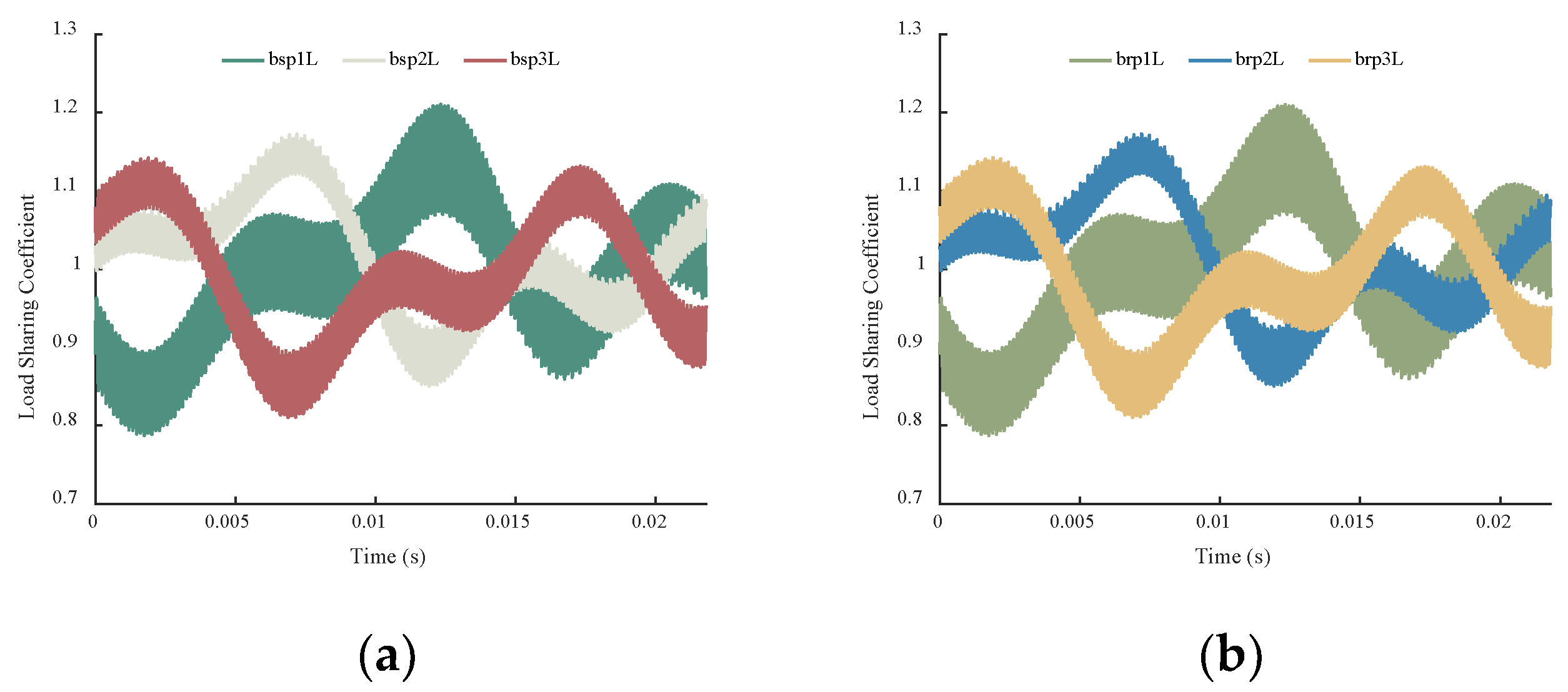
Variations in the dynamic LSCs in the differential PGT under external excitation: (a) left external meshing pairs; (b) left internal meshing pairs.
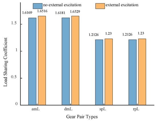
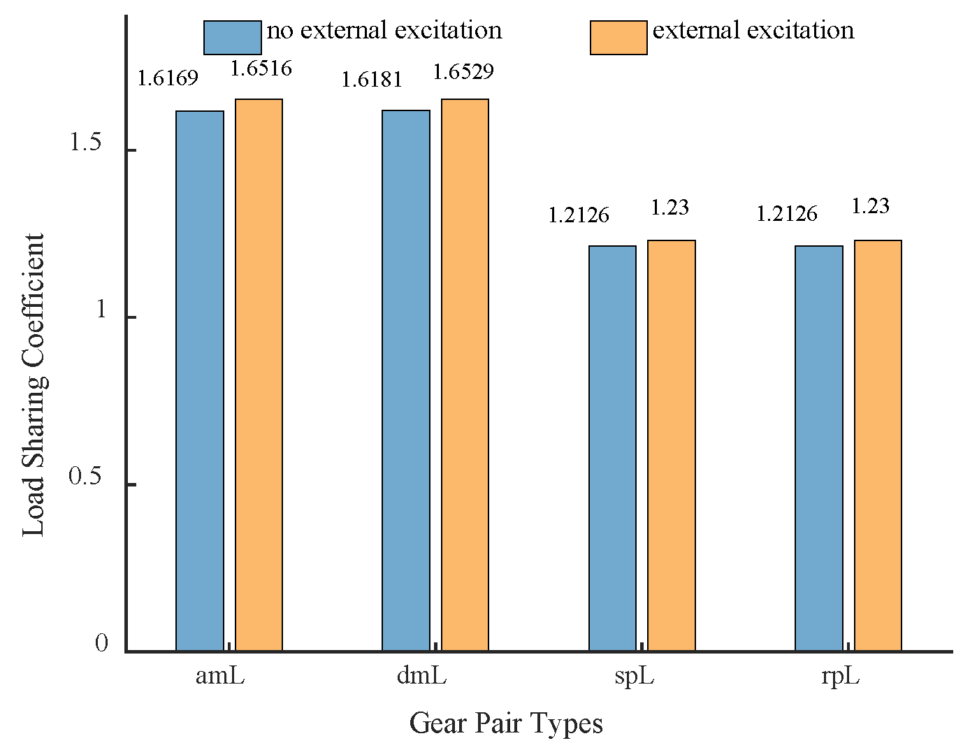
Figure 23.
Comparison of the dynamic LSCs of the transmission system with and without external excitation.
From Figure 21 and Figure 22, it can be observed that under the influence of internal excitations, the overall trend of the LSCs was similar to that under the rated condition. However, the LSCs become sharper due to the alternating external loads. Figure 23 indicates that considering the external excitation results in higher LSCs compared to the case without external excitation, indicating an uneven load distribution caused by the external excitation.
4.3.3. Dynamic LSCs under Different Input Torques
Using the dynamic LSCs on the left side as an example, the variations in the LSCs in the fixed-axes PGT and the differential PGT under the different input torques are shown in Figure 24 and Figure 25, respectively. The comparison of the dynamic LSCs under different input torques are shown in Figure 26.
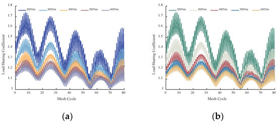
Figure 24.
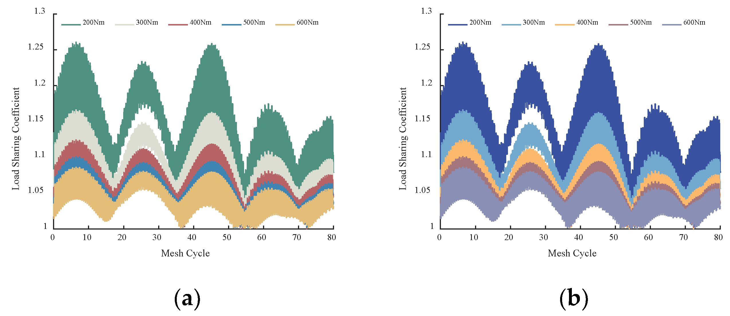
Variations in the dynamic LSCs in the fixed-axes PGT under the different input torques: (a) left external meshing pairs; (b) left internal meshing pairs.

Figure 25.
Variations in the dynamic LSCs in the differential PGT under the different input torques: (a) left external meshing pairs; (b) left internal meshing pairs.
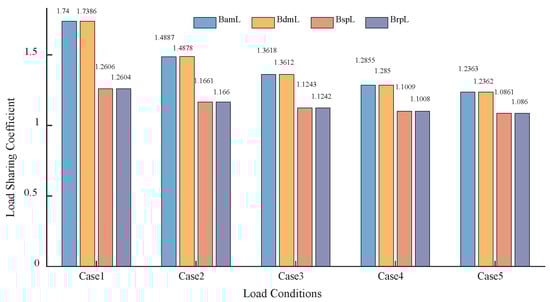
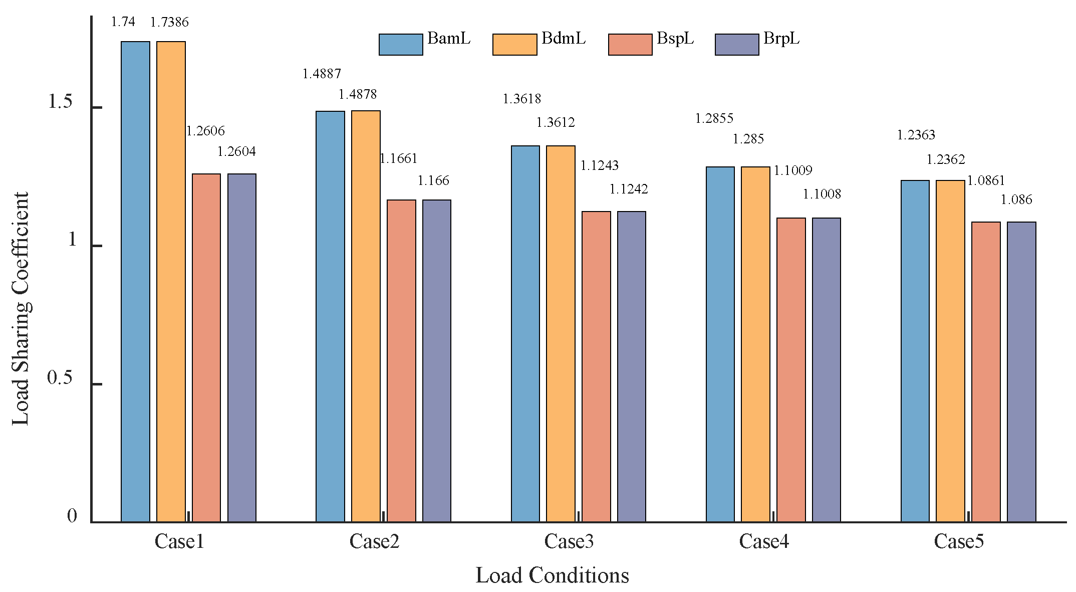
Figure 26.
Comparison of the dynamic LSCs of the transmission system under the different input torques.
From Figure 24 and Figure 25, it can be observed that the LSCs exhibited a sinusoidal-like variation pattern, fluctuating approximately every 18 meshing cycles. As the torque increased, the average values and magnitudes of the fluctuations of the LSCs exhibited a decrease. This is consistent with earlier observation that the smaller meshing forces were more susceptible to error-induced fluctuations. Figure 26 shows that with an increasing torque, the mean value of the LSC decreased from around 1.74 to around 1.23 for the fixed-axes PGT and from around 1.26 to around 1.08 for the differential PGT.
5. Model Validation
After analyzing the operating principles of the transmission system and the motion relationships among its components, all parts were treated as rigid bodies in the ADAMS dynamic simulation. All rotating components were constrained as revolute joints, and contact pairs were added between meshing gears.
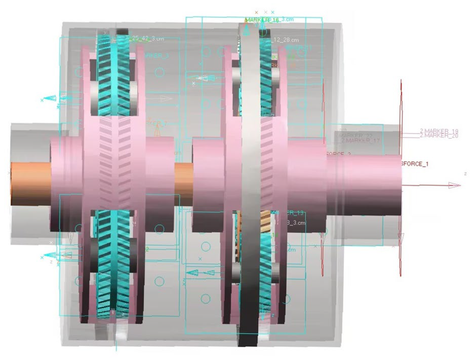
To validate the results of this study, a comparison was made between the meshing forces obtained from the ADAMS dynamic simulation and those obtained from the dynamic model. After analyzing the operating principles of the transmission system and the motion relationships among its components, all components were treated as rigid bodies in the ADAMS dynamic simulation. All rotating components were constrained as revolute joints, and contact pairs were added between meshing gears. A driving torque was applied to the sun gear, aL, while a load torque was applied to the ring gear, rR, and the carrier, h. The operating conditions were consistent with those in Section 4.1, and the constraints of the transmission system are illustrated in Figure 27.

Figure 27.
Constraints of the transmission system in the ADAMS dynamic simulation.
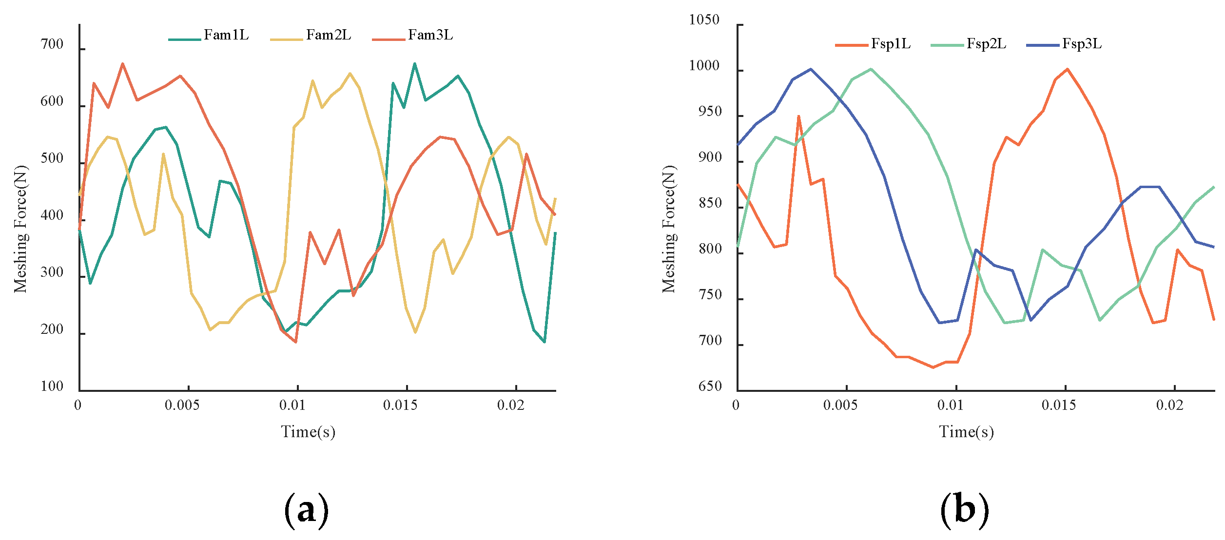
The simulation duration was set to 0.0218 s. Taking the meshing forces between the sun gear and planet gears on the left side of both the fixed-axes PGT and the differential PGT as examples, the meshing force curves were obtained, which are shown in Figure 28.
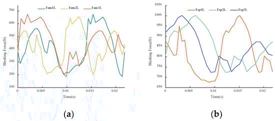
Figure 28.
Meshing force curves obtained from the ADAMS dynamic simulation: (a) left external meshing forces of the fixed axes PGT; (b) left external meshing forces of the differential PGT.
By comparing Figure 28a with Figure 7a and Figure 28b with Figure 8a, it can be observed that the meshing force curves obtained from the ADAMS dynamic simulation are generally consistent with those calculated by the model in terms of the numerical values and trend variations. Within the allowable range of error, this validates the reliability of the theoretical calculations.
6. Conclusions
A comprehensive dynamic model of the coaxial counter-rotating planetary transmission system is constructed. The model incorporated TMS, transmission errors, and external excitations. The primary objective of the investigation was to conduct an analysis of the meshing forces, displacements of the planet gears, and the performance of the load distribution in the transmission system.
Firstly, considering the translational and torsional vibrations of each component, a dynamic model of the coaxial counter-rotating planetary transmission system was established using the concentrated mass method. The dynamic equations of each component were derived based on the relative displacements between gear teeth.
Secondly, the dynamic meshing forces, planet gear displacements, and load-sharing characteristics of the coaxial counter-rotating planetary transmission system were investigated. The meshing forces acting on both sides exhibited significant similarities. When considering the external excitations, the variations in the meshing force curves became more pronounced. The radial displacements of the planet gears in the differential PGT were greater than that in the fixed-axes PGT. With an increasing input torque, the average displacements of planet gears in all directions tended to increase. The differential PGT, transmitting higher power, demonstrated a better load-sharing performance compared to the fixed-axes PGT.
In summary, this study explored the dynamic responses of the coaxial counter-rotating planetary transmission system under different operating conditions. It is noted that while the quantitative results presented are specific to the system studied, the qualitative findings are generally applicable to coaxial counter-rotating planetary transmission systems. Although the model established by the concentrated mass method may lack the accuracy of a finite element analysis, its computational efficiency is high, and the results are also close to reality. When performing strength, fatigue, reliability analysis, or parameter optimization for coaxial counter-rotating planetary transmission systems, this method can be utilized to quickly obtain data, such as meshing forces, vibration displacements, and load-sharing coefficients, serving as the basis for further work. Mechanical system designers can also use the main findings of this study as general guidelines for designing coaxial counter-rotating planetary transmission systems.
Additionally, we recognize the importance of analytical methods in system analysis and optimization. In the future, we plan to combine numerical methods with analytical methods, based on simplified assumptions, to simplify and extend the model developed in this study and to obtain exact solutions and optimization results under certain conditions. This approach not only reduces computational complexity but also provides a theoretical foundation for further optimization. We will continue to explore these directions in future research to enhance and refine the study of the dynamic characteristics of transmission systems.
Author Contributions
Conceptualization, Z.Y. and Z.C.; methodology, Z.Y.; software, J.Q.; validation, Y.L., M.D., S.M. and G.Y.; formal analysis, Z.Y.; investigation, Z.Y.; resources, Y.L.; data curation, M.D.; writing—original draft preparation, Z.Y.; writing—review and editing, Z.Y.; visualization, S.M.; supervision, G.Y.; project administration, G.Y.; funding acquisition, G.Y. All authors have read and agreed to the published version of the manuscript.
Funding
This research was funded by the Heilongjiang Key R&D Project (grant number: GA21D004), Heilongjiang Major Scientific and Technological Achievements Transformation Project (grant number: CG21B010), and Harbin University of Technology Scientific Research Initiation Fund Project (grant number: FRFCU5710052921).
Institutional Review Board Statement
Not applicable.
Informed Consent Statement
Not applicable.
Data Availability Statement
The data presented in this study are available upon request from the corresponding author. The data are not publicly available due to laboratory regulations.
Conflicts of Interest
The authors declare no conflicts of interest.
References
- Boguski, B.; Kahraman, A. An experimental study on the motion transmission error of planetary gear sets. Comput. Methods. Appl. Mech. Engrg. 2015, 283, 956–970. [Google Scholar]
- Shen, Z.; Qiao, B.; Yang, L.; Luo, W.; Yang, Z.; Chen, X. Fault mechanism and dynamic modeling of planetary gear with gear wear. Mech. Mach. Theory 2021, 155, 104098. [Google Scholar] [CrossRef]
- Xu, H.; Ren, H.; Qin, D. Dynamic characteristics of the planetary gear system with rolling bearing. Multibody Syst. Dyn. 2023, 59, 171–191. [Google Scholar] [CrossRef]
- Gu, X.; Velex, P. A dynamic model to study the influence of planet position errors in planetary gears. J. Sound Vib. 2012, 331, 4554–4574. [Google Scholar] [CrossRef]
- Gu, X.; Velex, P. On the dynamic simulation of eccentricity errors in planetary gears. Mech. Mach. Theory 2013, 61, 14–29. [Google Scholar] [CrossRef]
- Guo, Y.; Keller, J.; Parker, R.G. Nonlinear dynamics and stability of wind turbine planetary gear sets under gravity effects. Eur. J. Mech. A/Solids. 2014, 47, 45–57. [Google Scholar] [CrossRef]
- Huangfu, Y.F.; Dong, X.J.; Chen, K.K.; Li, Z.; Peng, Z. An insight into the pass effect of the planet gear from an elastodynamics perspective. Sci. China Technol. Sci. 2023, 66, 2415–2431. [Google Scholar] [CrossRef]
- Han, H.; Ma, H.; Tian, H.; Peng, Z.; Zhu, J.; Li, Z. Sideband analysis of cracked planetary gear train considering output shaft radial assembly error. Mech. Syst. Signal Process 2023, 200, 110618. [Google Scholar] [CrossRef]
- Wang, Y.; Liao, Y.; Xu, H. Effects of multi-excitation on vibration characteristics of planetary gear system. Alex. Eng. J. 2022, 61, 10593–10602. [Google Scholar] [CrossRef]
- Liu, C.; Yang, C.; Zhao, Y.; Luo, J.; Chen, X. Dynamic modeling and analysis of high-speed flexible planetary gear transmission systems. Alex. Eng. J. 2023, 80, 444–464. [Google Scholar] [CrossRef]
- Liu, J.; Li, X.; Xia, M. A dynamic model for the planetary bearings in a double planetary gear set. Mech. Syst. Signal Process 2023, 194, 110257. [Google Scholar] [CrossRef]
- Fyler, D.C.; Inalpolat, M. A dynamic model for double-planet planetary gearsets. J. Vib. Acoust. 2016, 138, 021006. [Google Scholar] [CrossRef]
- Guo, H.; Zhang, J.; Yu, H. Robust optimisation of dynamic and NVH characteristics for compound power-split hybrid transmission. Proc. Inst. Mech. Eng. K J. Multi-Body Dyn. 2019, 233, 817–826. [Google Scholar] [CrossRef]
- Tung, L.C.; Chan, Y.J. A time-variant dynamic model for compound epicyclic–cycloidal reducers. Mech. Mach. Theory 2023, 179, 105095. [Google Scholar] [CrossRef]
- Zhang, H.; Shen, X. A dynamic tooth wear prediction model for reflecting “two-sides” coupling relation between tooth wear accumulation and load sharing behavior in compound planetary gear set. Proc. Inst. Mech. Eng. C J. Mech. Eng. Sci. 2020, 234, 1746–1763. [Google Scholar] [CrossRef]
- Yang, L.; Yuan, B.; Gong, J.; Qin, M.; Liu, G. Dynamic modelling and vibration characteristics of a marine compound gear transmission system. Proc. Inst. Mech. Eng. K J. Multi-Body Dyn. 2023, 237, 261–278. [Google Scholar] [CrossRef]
- Li, W.; Li, Z. Dynamic analysis of a multi-stage gear system considering the coupling between mesh phasing angle and coaxial teeth ratio. Nonlinear Dyn. 2023, 111, 19855–19878. [Google Scholar] [CrossRef]
- Zhang, D.; Zhu, R.; Fu, B.; Tan, W. Modal properties of contra-rotating encased differential gear train used in coaxial helicopter. J. Vib. Eng. Technol. 2020, 8, 799–814. [Google Scholar] [CrossRef]
- Ryali, L.; Talbot, D. A dynamic gear load distribution model for epicyclic gear sets with a structurally compliant planet carrier. Mech. Mach. Theory 2023, 181, 105225. [Google Scholar] [CrossRef]
- Lai, J.; Liu, Y.; Xu, X.; Li, H.; Xu, J.; Wang, S.; Guo, W. Dynamic modeling and analysis of Ravigneaux planetary gear set with unloaded floating ring gear. Mech. Mach. Theory 2022, 170, 104696. [Google Scholar] [CrossRef]
- Wang, D.; Zhao, Y.; Ren, J.; Yu, S. Dynamic characteristics of the ring gear structure of two-stage plastic planetary reducers. J. Braz. Soc. Mech. Sci. Eng. 2023, 45, 474. [Google Scholar] [CrossRef]
- Cui, T.; Li, Y.; Zan, C.; Chen, Y. Dynamic modeling and analysis of nonlinear compound planetary system. Machines 2022, 10, 31. [Google Scholar] [CrossRef]
- Zhang, J.; Guo, H.; Yu, H.; Zhang, T. Numerical and experimental investigation on nonlinear dynamic characteristics of planetary gear train. J. Theor. Appl. Mech. 2020, 58, 1009–1022. [Google Scholar] [CrossRef]
- Peneva, M.; Radkova, K.; Troha, S.; Karaivanov, D. On the using of two-carrier planetary gear trains with two compound and four external shafts as change-gears. MATEC Web Conf. 2022, 366, 01007. [Google Scholar] [CrossRef]
- Shuai, M.; Ting, Z.; Guo-Guang, J.; Xiao-Lin, C.; Han-Jun, G. Analytical investigation on load sharing characteristics of herringbone planetary gear train with flexible support and floating sun gear. Mech. Mach. Theory 2020, 144, 103670. [Google Scholar] [CrossRef]


Disclaimer/Publisher’s Note: The statements, opinions and data contained in all publications are solely those of the individual author(s) and contributor(s) and not of MDPI and/or the editor(s). MDPI and/or the editor(s) disclaim responsibility for any injury to people or property resulting from any ideas, methods, instructions or products referred to in the content. |
© 2024 by the authors. Licensee MDPI, Basel, Switzerland. This article is an open access article distributed under the terms and conditions of the Creative Commons Attribution (CC BY) license (https://creativecommons.org/licenses/by/4.0/).