Article

Geometrical and Mechanical Modeling of Polymeric Multi-Ply Yarns

1
Department of Civil and Environmental Engineering, Politecnico di Milano, 20133 Milano, Italy
2
R&D Materials, Reinforcements Group, Pirelli Tyre SpA, 20126 Milano, Italy
*
Author to whom correspondence should be addressed.
Appl. Sci. 2024, 14(11), 4597; https://doi.org/10.3390/app14114597
Submission received: 30 April 2024 / Revised: 23 May 2024 / Accepted: 23 May 2024 / Published: 27 May 2024

Abstract

:
This work aims to describe and predict the complex mechanical behavior of polymeric cords used as reinforcements in tires. Starting from the observed microstructure of the cords and from macroscopic experimental tests performed on single-ply yarns, a comprehensive geometric and mechanical model is developed. The real geometry of the cord is replaced by an equivalent three-dimensional continuum of a cylindrical shape, with a properly defined non-isotropic inelastic constitutive behavior. The three-dimensional viscoelastic and viscoplastic material model developed by the authors for rayon fibers is employed for this purpose. The actual directions of filaments inside the cord are computed by an analytical model, accounting for the twist in the yarns and in the filaments inside each yarn. Such directions, relevant to points of the cord cross-section, are then averaged along the pitch of the cord to obtain mean directions which represent the virtual reinforcement directions to be used in the equivalent cylindrical-shaped model. This analysis strategy is implemented in a finite element procedure. For rayon cords, the developed simulation tool (fed with appropriate parameters) gives numerical results that compare well with the corresponding experimental results. This approach could be effectively utilized in the analysis of cord-reinforced rubber composites.

1. Introduction

Twisted polymeric multi-ply yarns, also called cords, are increasingly used as reinforcements embedded in rubber compounds to form the composite layers that make up the structure of pneumatic tires [1].
Different polymeric cord materials as well as cord constructions can be employed as tire reinforcements, and many experimental investigations have been conducted over the years to explore the mechanical behavior of the various cord types. In [2], the viscoelastic properties of rayon, nylon and PET cords are studied under different temperature and humidity conditions, and considering different geometric structures (number of plies, twist levels) of the reinforcements. Tests on nylon/PET hybrid cords [3] and on aramid/nylon hybrid cords [4] have been also carried out and discussed. Experimental studies on the tensile behavior of aramid and polyamide cords are reported in [5]. Cyclic tests on nylon66 cords are described in detail in [6]. Test results on rayon greige and dipped cords are described later on in this work; they have recently been obtained within an experimental campaign that complements the one reported in [7,8].
As for the mechanical modeling of cords, intensive research has been conducted on this topic for many years. Various approaches with different levels of sophistication have been proposed. The cord modeling presents many difficulties related to the manifestation of geometrical and material non-linearities, and to the lack of precise information about the initial geometrical arrangements of the fibers. For this reason, in some of the approaches proposed for the modeling of cord–rubber composites, cords are represented in a simplified way without considering their actual filament-based twisted structure. This is exemplified for instance in [9] and in [10] where 3D FE analyses of fiber-reinforced composites are developed, with cords represented by rebar layers containing Gauss points at which the cord material, assumed in a uniaxial stress state, follows a hyperelastic law.
Other more complex approaches for the simulation of composites in finite strains have been developed more recently, in which the twisted fiber geometry of the reinforcements is explicitly considered together with advanced constitutive modeling for both the elastomer matrix and the cord material. A representative study of this type is [11] in which a preliminary FE simulation is performed to obtain a realistic initial geometry of the cord filaments and an elasto-plastic cord behavior is assumed. In [12], a flax–fiber/epoxy composite is analyzed and an anisotropic model for fibers is developed.
In [13], the present authors, in the framework of the thermodynamics of irreversible processes [14], developed a new transversely isotropic viscoelastic–viscoplastic constitutive law intended to model fibrous materials. The model was applied to describe the mechanical behavior of single-ply yarns, replacing their real geometry with an equivalent three-dimensional continuum of cylindrical shape. The material direction of transverse isotropy was fixed considering the filaments arranged as concentric helices, with a local tangent unit vector a . The non-linearity of the uniaxial tensile force–strain response of the yarn was then attributed to the combined effect of twist and of the viscoplastic behavior of the filament material. This model, at difference from the hyperelastic constitutive laws (e.g., the well known Yeoh’s and Marlow’s ones [15,16]), allows prediction of the experimental cyclic behavior with permanent strains as well as the effect of twist.
The purpose of the present work is to develop a model able to predict the complex inelastic behavior of multi-ply yarns accounting for the fiber orientation. To this end, we extend the above approach to multi-ply yarns by developing a proper strategy to define an equivalent virtual fiber orientation at each point of the cord, to fix the material direction of transverse isotropy. Figure 1 schematically shows the definition of material directions in a balanced rayon cord composed of two yarns and the equivalent representation through a continuum cylinder with anisotropic properties. The blue and red lines refer to fibers belonging to the two yarns.
The paper is organized as follows. Section 2 first introduces the model employed to describe the fiber direction inside a multi-ply yarn and the approach here proposed to define a mean direction in each point of a homogenized equivalent solid. Then, the model formulated in [13] for rayon filaments is summarized and extended to include isotropic hardening and different elastic behavior in tension and compression. In Section 3, the model parameters are first identified on the basis of experimental results obtained in tension tests on untwisted and twisted yarns; then, the model and the proposed approach are validated by simulating uniaxial tension test on two-ply cords. The effect of dipping is also effectively simulated. Section 4 contains a critical discussion of the obtained results and concludes the paper.

2. Materials and Methods

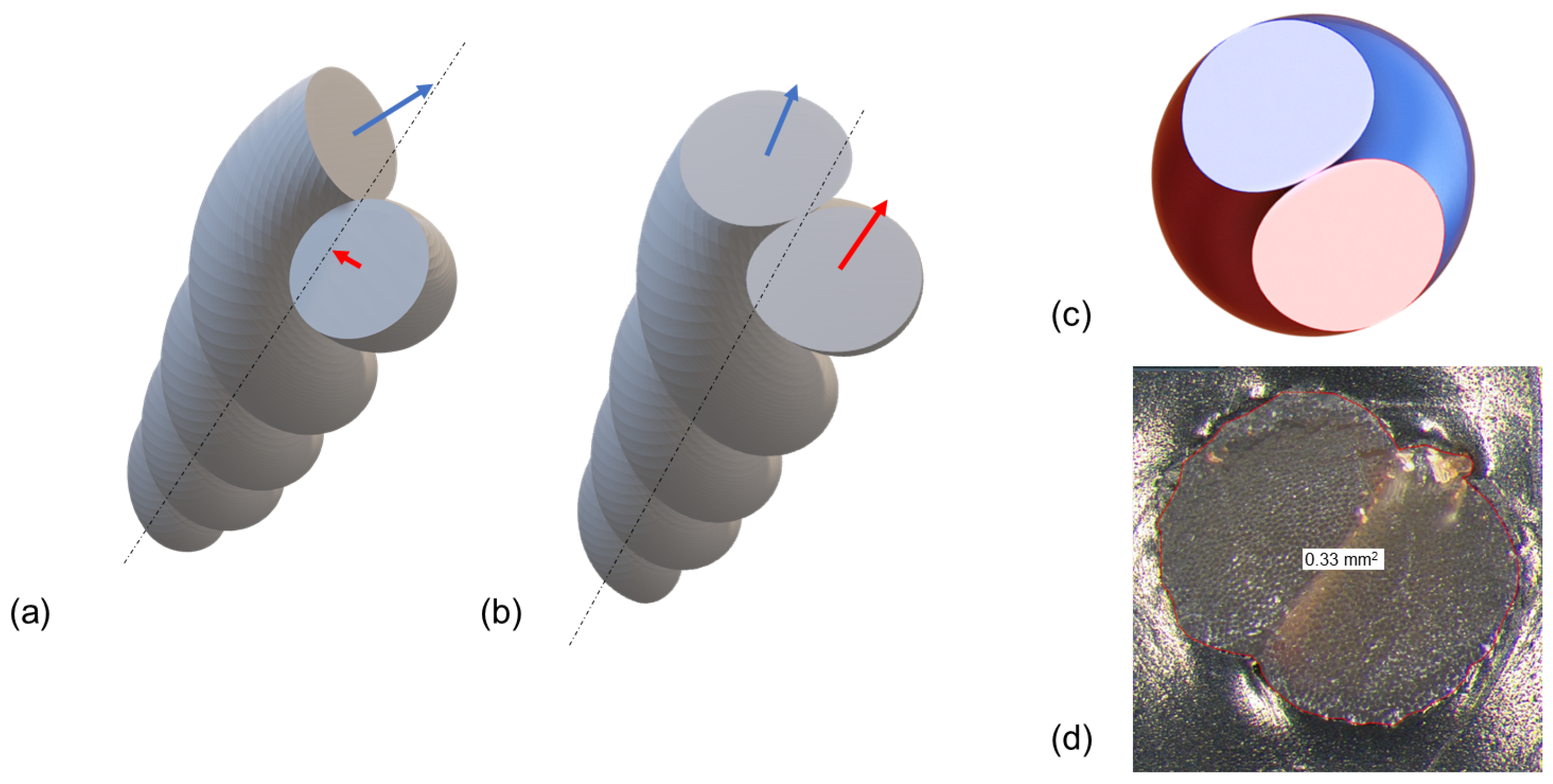
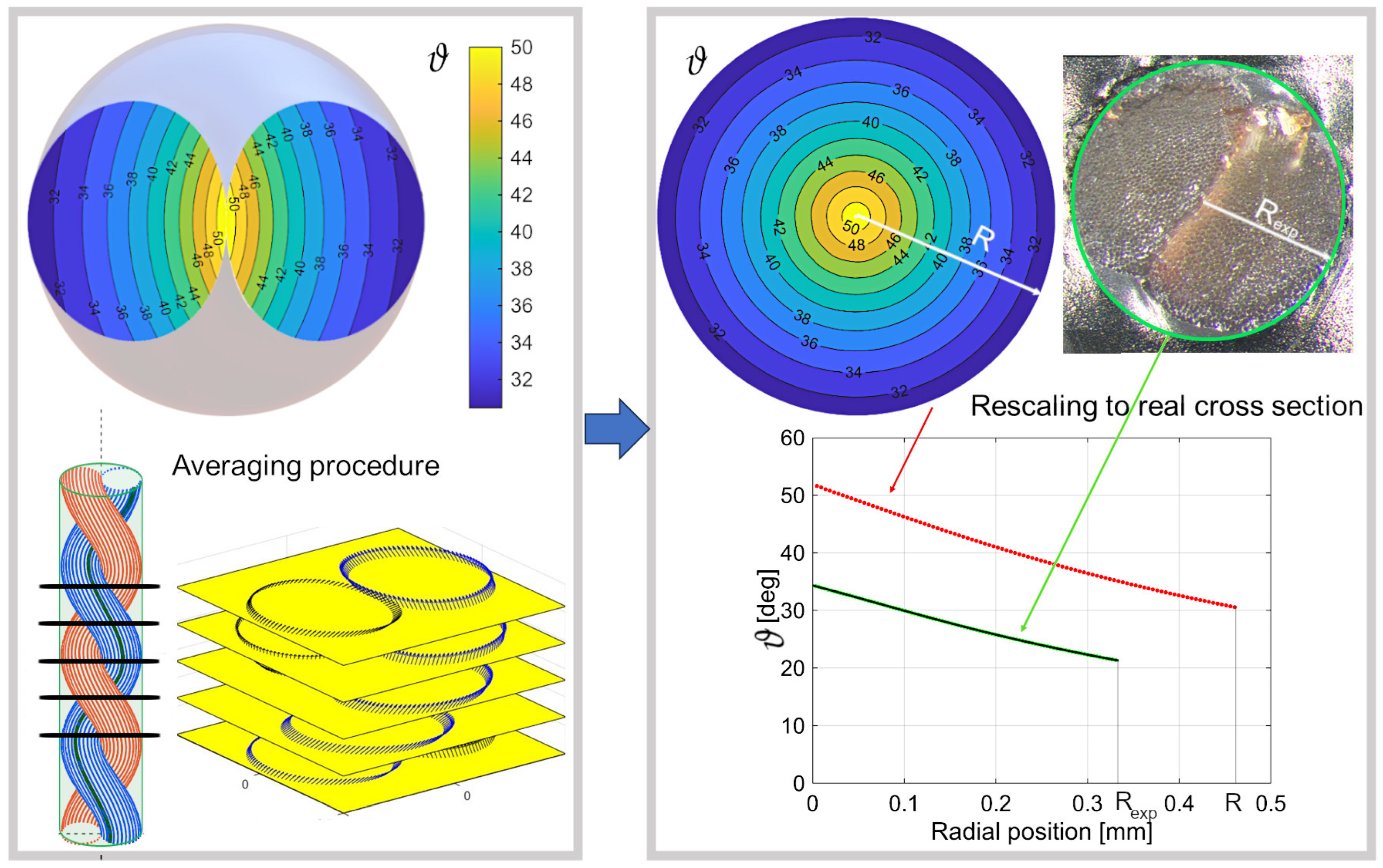
2.1. Geometrical Model of Multi-Ply Yarns

The mechanical behavior of twisted multi-ply yarns (also referred to as cords) is strongly dependent on the local orientation of fibers, i.e., on the angle each fiber forms with the axis of the cord. This angle depends on the twist n of the single-ply yarns and on the twist N of the yarns to obtain the cord.
The experimental determination of the real trajectories of fibers is difficult and would require ad hoc microtomography measurements, as in [17], which are not available for the cords considered in this work.
Therefore, we here follow the theoretical formulation developed in [18] considering that the individual filaments in the cord follow a “doubly wound” helix. With reference to Figure 2a, we define an orthogonal reference frame with the cord axis aligned with x 3 and the cord section in the plane x 1 x 2 . The axis of each yarn composing the cord forms an ideal helix of radius b and twist N around the cord axis as represented by the dashed line in Figure 2a. The helix angle Θ of the yarn axis is related to the cord twist N by
tan Θ = 2 π N b .
The filaments inside the yarn are, in turn, wound around the yarn axis with relative inclination linearly depending on their distance ρ from the yarn axis (see blue line in Figure 2a). Before cording, the single yarn radius is R y and, thus, the helix angle δ of the outmost fiber is related to the yarn twist n by
tan δ = 2 π n R y .
In [18], a parameter p depending on the two twists ( n , N ) and defining the construction of the cord is introduced. If the cord twist is small, this parameter can be approximated as p = n / N and in that case the most common construction, i.e., the balanced one, corresponds to p = 1 . In general, a more complex expression of p must be considered
p = 2 π n 1 b sin Θ
where 1 and are the non-dimensional lengths of the yarn axis before and after cording. Following the development in [18], for the case of a two-ply cord, they read
1 = 2 R y 2 4 π 2 n 2 ( 1 + R y 2 4 π 2 n 2 1 )
= 1 sin 2 Θ cos 2 Θ ( 2 + 1 R y 2 π n sin Θ cos Θ ) + 2 1 + sin 2 Θ cos 2 Θ + 1 R y 2 π n sin Θ cos Θ
Note that in the original work, is derived as the solution of a second-order equation and, hence, two expressions are given; however, one can show that the only physical solution leading to a positive is that given in Equation (5).
Figure 2b shows the variation in p with the twist in a balanced two-ply cord for two different yarn radii: the difference with the approximate value p = n / N = 1 increases with twist and yarn radius.
It should be remarked that, even though in recent literature the value p = n / N = 1 is assumed for balanced cords without discussion, the error can be significant and such a value does not correspond to the original theory [18].
Let us consider a fiber identified by the distance ρ from the yarn axis and let the angle ϕ , measured with respect to the principal plane of curvature of the yarn axis, define the position. The angle ϑ between the cord axis and the tangent to a fiber at that point, as computed in [18,19], reads
ϑ ( ρ , ϕ ) = arctan b 2 + ( p 2 + cos 2 Θ ) ρ 2 sin 2 ϕ + ( 1 + p 2 cos 2 Θ ) ρ 2 cos 2 ϕ + 2 b p ( 1 + p cos Θ ) cos ϕ + 2 p cos Θ ρ 2 b cot Θ p sin Θ ρ cos ϕ .
For a two-ply cord, b coincides with the yarn radius R y . The envelope of all the fibers of the yarns defines the geometry of the cord according to Treloar’s theory. Such idealized geometry is shown in Figure 3. The arrows define the normal to the right cross-sections of the yarns in Figure 3a and to the sections of the yarns along a plane perpendicular to the cord axis in Figure 3b. Due to the curvature of the yarns’ axes, a yarn cut with a plane orthogonal to the cord axis does not give rise to an ellipse (see Figure 3c). The shape of the idealized cord section is in qualitative agreement with the real one shown in Figure 3d.
The value of the fiber inclination ϑ obtained through Equation (6) on the cross-section of a two-ply cord is shown in Figure 4 (top-left). The variation in ϑ indicates that the single fibers in the cords are not helices but curves with varying inclination angles along a single pitch. Furthermore, the inclination increases as they approach the cord axis. We then compute the mean value of ϑ over a pitch by considering the rotation of the cross-sections along the cord axis (see Figure 4 bottom-left). The obtained mean value is hence defined on the circle of radius R obtained by rotating the two yarn sections. This mean value turns out to be axial-symmetric ϑ = ϑ ( r ) , 0 r R (see Figure 4 top-right), as in the case of a single yarn with the model of coaxial helices. However, differently from that case, here, the most inclined fibers are near the center of the cord. This is in qualitative agreement with the tomographic measurements reported in [17]. Furthermore, by taking the mean value of the other components of the unit vector a , one obtains that the mean inclination of the fibers follows that of concentric helices in the homogenized cylinder of radius R which envelops the two yarns.
Finally, the experimental area of the cord, which is of course smaller than the circle of radius R = 2 R y , must be considered and a rescaling of the ϑ ( r ) must be performed accordingly. Knowing the actual value A e x p = 0.33 mm2 of the cross-section area, the rescaling is performed approximating the real cross-section by a circle of radius R e x p = A e x p / π and considering that the transformation preserves the length of fibers. The final radial distribution of the mean inclination angle to be used in the analyses hence reads
ϑ * ( r * ) = arcsin ( sin ( ϑ ( r ) ) r * r ) , r * = r R e x p R .
ϑ ( r ) and ϑ * ( r * ) are shown in Figure 4 (bottom-right) by the red and green curves, respectively.

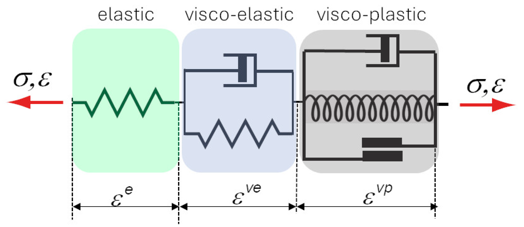
2.2. Anisotropic Viscoelastic–Viscoplastic Model

The transversal isotropic elasto-viscoplastic model developed in [13] is here assumed. Isotropic hardening is also included in the present work. Figure 5 shows schematically the assumption of strain additivity between elastic, viscoelastic and viscoplastic contributions.
The governing equations of the model read
σ = C : ( ε ε v e ε v p )
χ = h γ
X = H α
X n = H n α n
ε ˙ v e = Ξ 1 : ( σ C ˜ : ε v e )
ε ˙ v p = φ η sign ( ( σ X X n ) : ( a a ) ) ( a a )
γ ˙ = φ η
α ˙ = ε ˙ v p
α ˙ n = ε ˙ v p φ η B H n X n
φ = | ( σ X X n ) : ( a a ) | σ y χ
Equations (8)–(11) express the linear state laws relating the static variables (stress σ , static internal variables of isotropic hardening χ , and of linear and non-linear kinematic hardening X and X n ) to the conjugate kinematic ones (elastic strain ε e = ε ε v e ε v p , kinematic internal variables of isotropic hardening γ , and of linear and non-linear kinematic hardening α and α n ).
In Equation (8), C is the elastic stiffness of the transversely isotropic material:
C = λ I I + 2 μ P I + α ( a a I + I a a ) + 2 ( μ L μ P ) A + β a a a a
where a is the vector defining the fiber direction, I is the second-order unit tensor, I is the fourth-order unit tensor and A is a fourth-order tensor whose components are given by the following:
A i j k l = 1 2 ( a k a i δ j l + a i a l δ j k + a j a k δ i l + a j a l δ i k ) .
The stiffness matrix depends on five material parameters: μ L , μ P are the shear moduli, respectively, along the fiber direction a (index L) and in the plane of isotropy (orthogonal to a , index P), and λ , α and β are three material constants that can be derived from the more usual engineering elastic constants E L , E P , ν P and ν P L , as shown in [13]. The material parameter h governs the isotropic hardening, assumed linear for simplicity, while H and H n define the linear and non-linear kinematic hardening.
Equation (12) expresses the evolution law of the viscoelastic strain ε v e having assumed linear viscoelasticity in the Voigt form, with C ˜ having the same form as C , but with five different material parameters. Even though in principle one can identify all five parameters independently, to reduce the number of parameters, we here assume proportionality between the two elasticity tensors
C ˜ = c ˜ C .
Similarly, Ξ is a fourth-order tensor, depending on five retardation times (cp. [13]). Here, a single retardation time is considered for simplicity, hence assuming
Ξ = θ ˜ c ˜ C .
Equations (13)–(16) express the evolution laws for the viscoplastic variables. All of them evolve together and are proportional to the positive part φ of the yield function φ ; η is a positive viscosity parameter. The yield function depends on the projection of the over-stress in the fiber direction. Further details are given in [13].
Even though the filaments are twisted together, they are easily subject to instability phenomena when compressed. This leads to a very low effective stiffness in compression. To account for the different behavior when the fibers are subject to tension or compression, we develop in this work a “piecewise” linear formulation of the model in the sense specified in [20]. We consider that a material point is in a “state of tension” when the elastic strain along the fiber direction is positive, while it is in a “state of compression” when the elastic strain along the fiber is negative. Accordingly, the elastic stiffness C defined by relation (18) must be piecewise constant, depending on the sign of the elastic strain along the fibers. The elastic strain space is thus subdivided into two sub-domains by an interface that contains the origin. A jump for some of the elastic moduli is then considered. The values of the elastic constants for tension and compression will be denoted by λ + , α + , β + , μ L + , μ P + and λ , α , β , μ L , μ P , respectively.
We assume the material to preserve its symmetries in both “tensile” and “compressive” states. Additionally, to enforce continuous differentiability of the stress–strain law, the interface must be a linear function of the elastic strain (note that global convexity of the elastic potential and global invertibility of the stress–strain law are also automatically enforced by our model) (see [20] for further details). Consequently, defining a scalar-valued tensor function g ( ε e ) , given by a linear combination of the linear invariants I 1 : = tr { ε e } and I 2 : = tr { ( a a ) · ε e } , the interface can be expressed by the condition:
g ( ε e ) : = γ 1 I 1 + γ 2 I 2 = 0 ,
where γ 1 and γ 2 are two scalars defining the orientation of the interface. Finally, exploiting again the continuity of the stress function, the following conditions on the jumps of the material parameters apply:
λ + λ = J γ 1 2 , α + α = J γ 1 γ 2 , β + β = J γ 2 2 , μ L + = μ L , μ P + = μ P ,
where J is a parameter defining the jump. From (23), one can recognize that the material constants μ L and μ P cannot jump. This is the proper setting to model the linear elastic response of a bimodular transversely isotropic material.
In our case, we select γ 1 = 0 and γ 2 = 1 in the above relations (22) and (23). The states of tension and compression are thus defined as follows:
I 2 0 : tension I 2 < 0 : compression

3. Results

All experimental results used in this work have been obtained in a recent extensive experimental campaign on rayon yarns and cords performed in the laboratories of Indorama Ventures Mobility Cremona SpA. To limit uncertainties related to the raw material and laboratory conditions, all specimens were directly prepared and conditioned in the laboratory starting from the same rayon filaments in the form of untwisted bundles, here called Y0, with a linear density of 1840 dtex. From that material, twisted yarns with 480 twists per meter (here called Y48) have been fabricated and from the latter balanced two-ply cords (here called C2) have been obtained. In tire production, the cords are subject to a dipping process to increase adhesion between the reinforcement cords and the rubber matrix. Also, dipped cords (here called DC2) have been tested. All tests were performed in a climatic chamber at 65% RH and 20 °C after 24 h’ conditioning of the material.

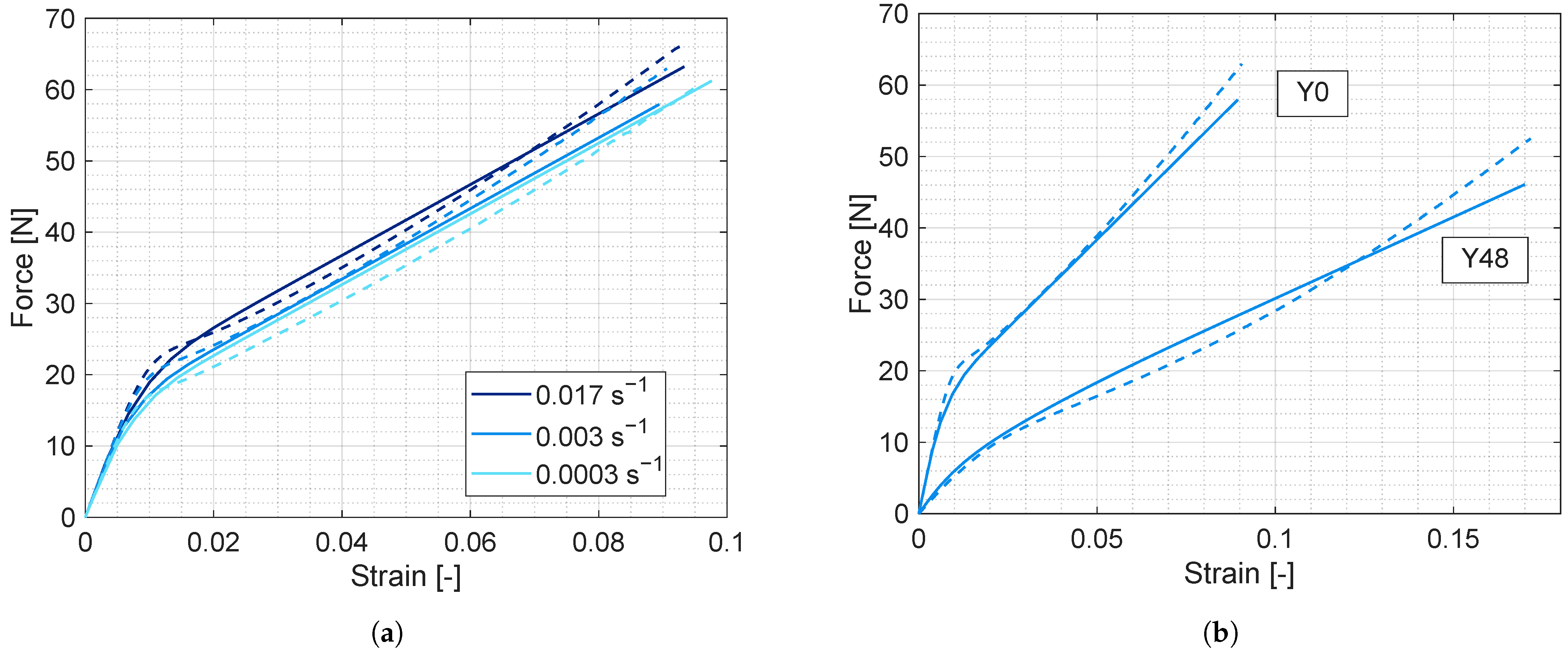
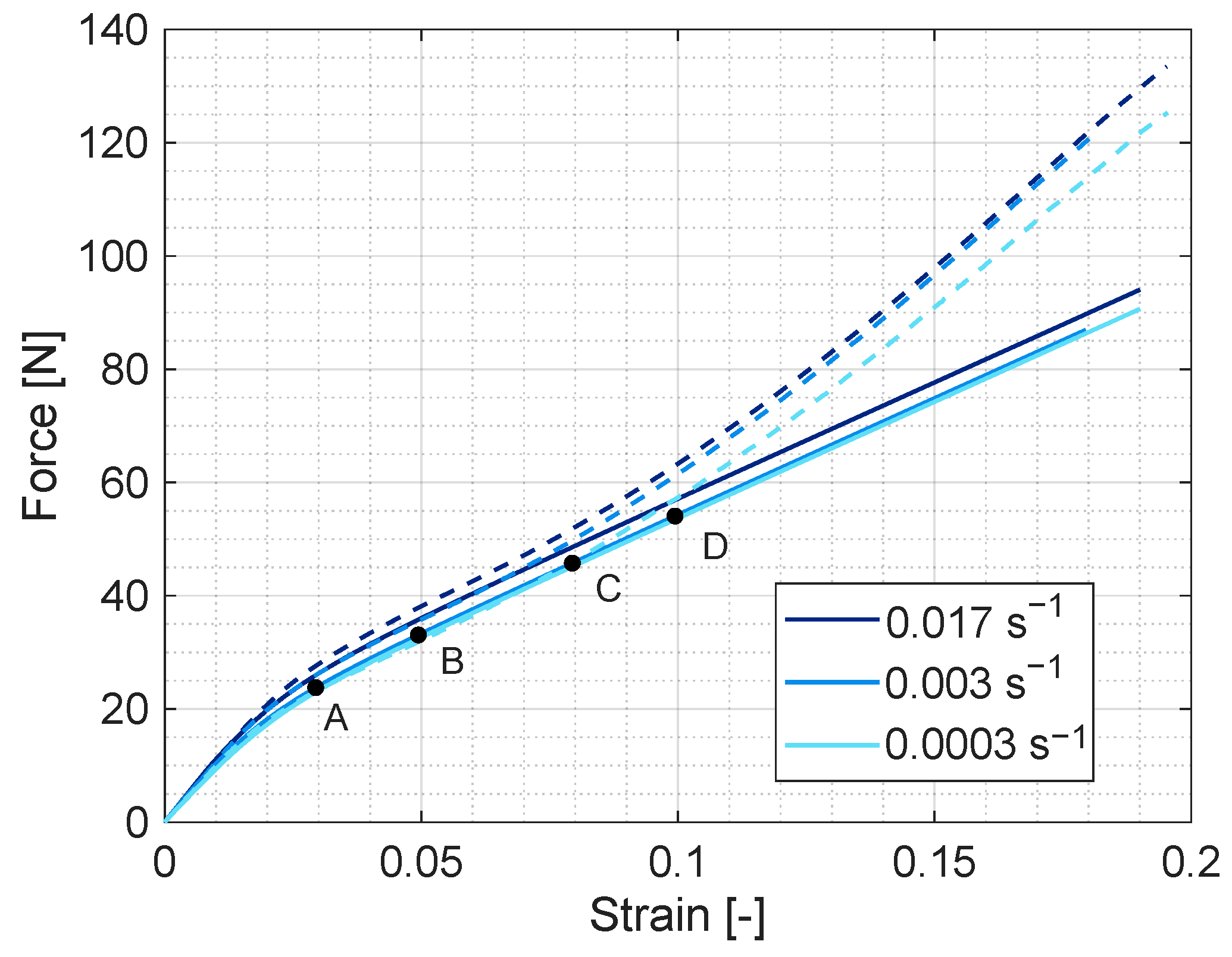
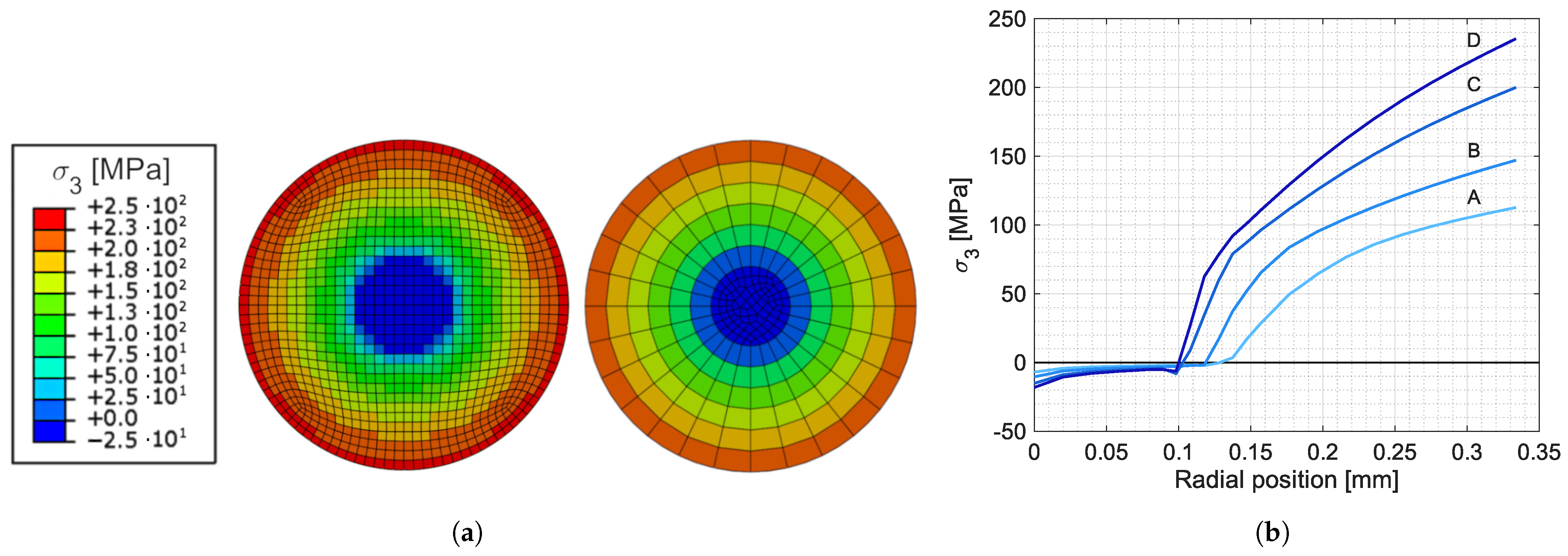
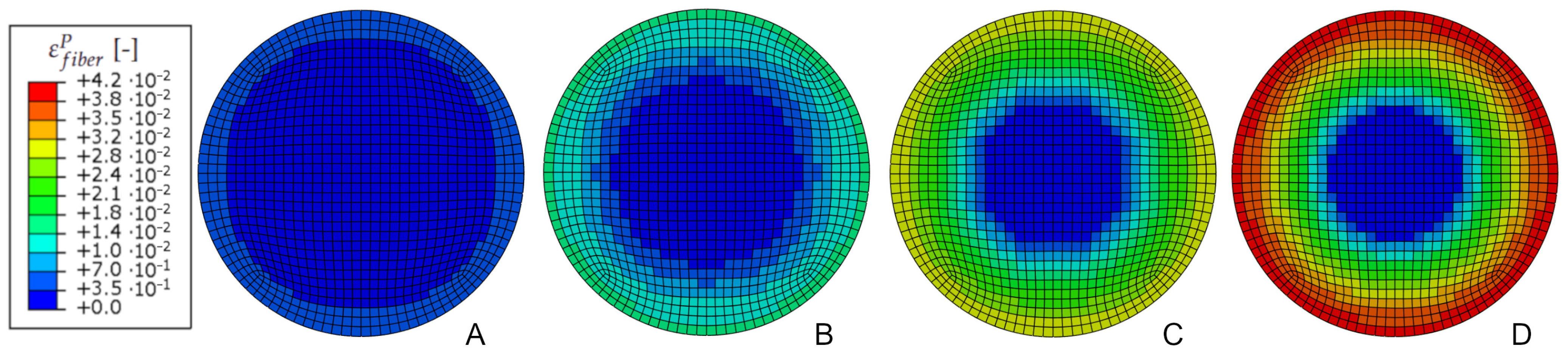
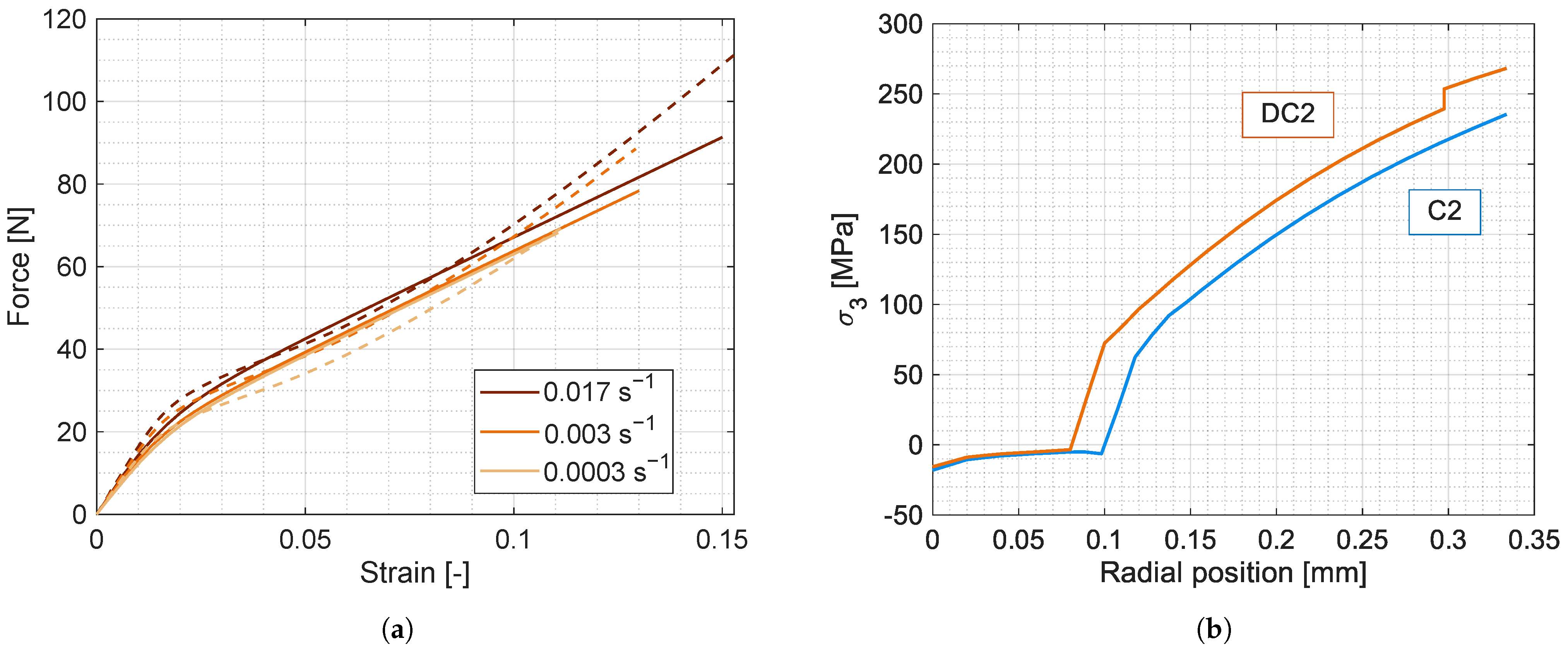
3.1. Model Calibration on Uniaxial Tensile Tests on Yarns

First, the model parameters are identified on the basis of the experimental data of tensile tests performed on untwisted yarns Y0 at different strain rates and on twisted yarns Y48 at a strain rate of 0.003 s−1. While for Y0 all fibers have the same direction, aligned with the yarn axis, for Y48 one has to consider the variation of fiber direction with the radial position. We here make use of the coaxial helix model, as in [13], and, accordingly, we define the axis at transversal isotropy at each point of the equivalent cylinder used in the numerical simulations. The identified material parameters are reported in Table 1, while Figure 6a,b show the experimental curves (dashed lines) together with the model predictions after parameter identification (solid lines).
In tension tests on yarns, the elastic strain in the fiber directions at any point is positive. Therefore, only elastic constants in tension (index +) are identified. Actually, in view of the choice of the interface made in the present work (Equation (24), E L is the only variable that has different values in tension and compression so that only β has a jump across the interface as required by (23). The value of E L cannot be identified from the above tests. We hence use the ratio E L / E L + reported in the literature [21] to set the value of E L .

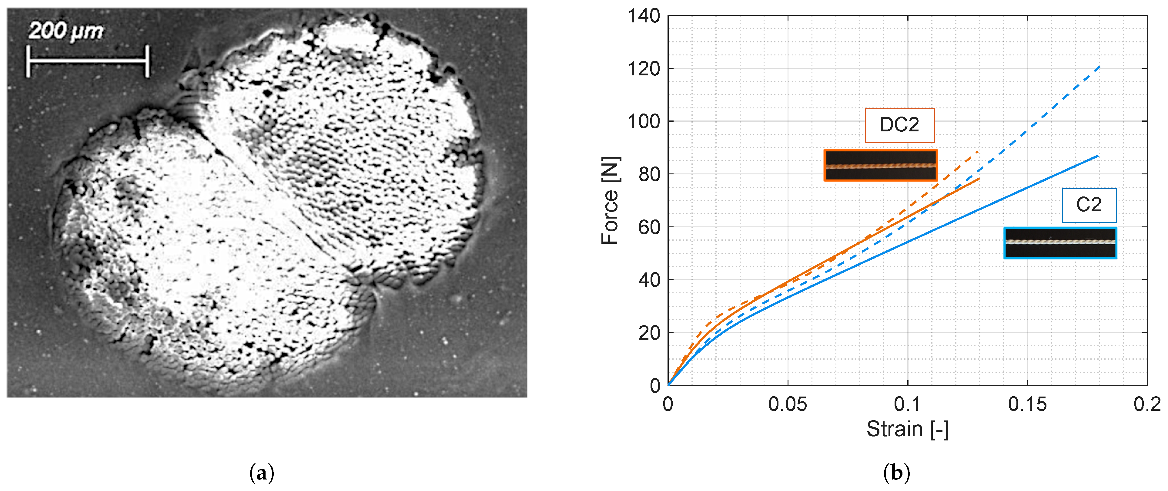
3.2. Tensile Tests on Two-Ply Greige and Dipped Cords

To simulate the behavior of cords, we first compute the distribution of the mean fiber inclination on an equivalent cylinder, following the procedure described in Section 2.1. This mean inclination is then assigned to each Gauss point of the mesh of the equivalent cylinder employed in numerical analyses. The material parameters previously identified using results on single-ply yarns (as in Table 1) are adopted.
Figure 7 shows the comparison of experimental (dashed lines) and numerical (solid lines) results in terms of global force vs strain curves for uniaxial tensile tests conducted at different strain rates. A good agreement is observed for strain below 0.1. The model is able to predict the correct stiffness of the cord both in the initial linear elastic part and in the following non-linear elasto-plastic one. For very large strains, the experimental curves show a significant locking effect due to the variation in fiber inclination occurring at large imposed cord elongation which cannot be predicted in the small strain frame adopted in our modeling.
Figure 8a shows the contour plot of the axial stress on the cross-section for ε = 0.1 obtained with an axial-symmetric coarse mesh and a structured refined mesh. One can observe a good agreement between the results obtained with the two meshes. It is worth noting that a small central region of the cord is subject to compressive stresses. This counter-intuitive effect is the result of the fiber inclination, which is higher in the central part of the cord than in the external one. The variation of the axial stress along the radius for different imposed strains (marked by dots in Figure 7) is shown in Figure 8b. The effect of the reduced stiffness of the fibers in compression, which limits the compressive stress value, is visible. The boundary between the compression and the tension regions evolves during the cord stretching due to the progressive inception of plasticity (from the external layers to the internal ones). This progressive development of plastic strain can be seen in Figure 9 which shows the contour plots of the plastic strain in the fiber direction at different imposed strains marked by the letters A, B, C and D in Figure 7.
The effect of dipping on the uniaxial mechanical response of cords has been also considered. During the dipping process, the adhesive material penetrates the external layers of fibers for a thickness of two or three filaments, visible in the microscopic image of Figure 10a as darker filaments. This treatment increases the stiffness of the cord and reduces the failure strain. Figure 10b compares the experimental uniaxial response of greige (in blue, dashed) and dipped (in orange, dashed) for a test at ε ˙ = 0.003 s 1 .
To simulate the effect of dipping we consider enhanced material properties in the external part of a cylinder, in a layer of 36 µm thickness, in agreement with the microscopy image in Figure 10a. In particular, the properties defining the stiffness in the plane transversal to the fiber have been increased: E P was changed to 1500 MPa, ν P to 0.3 and μ L to 320 MPa. Figure 11a shows a comparison between the numerical prediction thus obtained (solid lines) and the experimental results (dashed lines) in terms of force versus strain for tension tests at different strain rates. A good agreement is observed. The model is able to describe the different behavior of greige and dipped cords, as shown in Figure 10b.
Figure 11b shows the axial stress distribution inside greige and dipped cords. The presence of the adhesive increases the stiffness of the external layer, modifying the axial stress distribution and inducing its discontinuity.

4. Discussion

In this work, we have formulated a new approach for the simulation of the inelastic behavior of polymeric greige and dipped multi-ply yarns. The model has here been applied to rayon cords, but the same model, with proper parameter identification, could also be used for other polymeric cords, such has those made of PET or nylon.
The model is fully three-dimensional and accounts for permanent viscoplastic strains and for the different behavior in tension and compression. Hence, it can be used in three-dimensional analyses of rubber reinforced composites in different loading conditions such as monotonic and cyclic bending.
The model here developed also allows the estimation of the local distribution of stresses and strains which crucially depends on the fiber inclination and hence on the construction of the cord. Therefore, the present contribution opens the way to an optimization of the cord construction to minimize, e.g., the peaks of stress inside the reinforcement.
The proposed approach for the simulation of the mechanical behavior of twisted multi-ply yarns proves effective for a qualitative prediction of global force–strain response at different imposed strain rates. The quantitative agreement with the experimental results is very good for imposed cord axial strain up to 10%. For higher levels of strain, the model should be enhanced by considering the re-alignment of the fibers with the imposed strain. This extension will be pursued in coming researches.
Further research is also needed to include the effects of thermal cycles: this is of paramount importance to interpret the behavior of cords during tire construction and operational conditions.

Author Contributions

Conceptualization, C.C. and G.N.; methodology, C.C., M.M. and G.N.; software, M.M. and L.P.d.C.; validation, M.M. and L.P.d.C.; data curation, P.C., M.M. and L.P.d.C.; writing, C.C. and G.N.; supervision, C.C. and G.N.; project administration, P.C. and C.C. All authors have read and agreed to the published version of the manuscript.

Funding

This work has been carried out in the framework of the Joint Research Platform between Politecnico di Milano and Pirelli Tyre SpA.

Institutional Review Board Statement

Not applicable.

Informed Consent Statement

Not applicable.

Data Availability Statement

Data is contained within the article.

Acknowledgments

The authors wish to acknowledge Angelo Anelli of Indorama Ventures Mobility Cremona SpA for his continuous support during the experimental tests.

Conflicts of Interest

Paola Caracino is employed by Pirelli Tyre SpA. The remaining authors declare that the research was conducted in the absence of any commercial or financial relationships that could be construed as a potential conflict of interest.

Abbreviations

The following abbreviations are used in this manuscript:
Y0Untwisted yarn
Y48Yarn with 480 turns per meter
C2Cord made of two yarns Y48
DC2Dipped cord C2

References

  1. Rodgers, B. Tire Engineering: An Introduction, 1st ed.; CRC Press: Boca Raton, FL, USA, 2020. [Google Scholar] [CrossRef]
  2. Willett, P.R. Viscoelastic Properties of Tire Cords. J. Appl. Polym. Sci. 1975, 19, 2005–2014. [Google Scholar] [CrossRef]
  3. Aytaç, A.; Yilmaz, B.; Deniz, V. Nylon 66/Polyester Hybrid Cords: 1. Design and Investigation of Properties. Fibers Polym. 2011, 12, 252–257. [Google Scholar] [CrossRef]
  4. Yilmaz, B. Aramid-nylon 6.6 hybrid cords and investigation of their properties. Rubber Chem. Technol. 2012, 85, 180–194. [Google Scholar] [CrossRef]
  5. Bogusz, P.; Miedzińska, D.; Wieczorek, M. Experimental Investigation of the Tensile Behavior of Selected Tire Cords Using Novel Testing Equipment. Materials 2022, 15, 4163. [Google Scholar] [CrossRef] [PubMed]
  6. Krmela, J.; Michna, M.; Růžička, Z.; Krmelová, V.; Artyukhov, A. Cyclic Testing of Polymer Composites and Textile Cords for Tires. Polymers 2023, 15, 2358. [Google Scholar] [CrossRef] [PubMed]
  7. Caracino, P.; Agresti, S.; Pires da Costa, L.; Novati, G.; Comi, C. The nonlinear behaviour of cords to be used in rayon-rubber composites. In Constitutive Models for Rubber XII; Marano, C., Briatico Vangosa, F., Andena, L., Frassine, R., Eds.; CRC Press: London, UK, 2022; pp. 472–476. [Google Scholar] [CrossRef]
  8. Pires da Costa, L.; Novati, G.; Caracino, P.; Comi, C.; Agresti, S. Tensile behaviour of rayon cords in different conditions. Mater. Res. Proc. 2023, 26, 133–1388. [Google Scholar] [CrossRef]
  9. Meschke, G.; Helnwein, P. Computational Mechanics Large-strain 3D-analysis of fibre-reinforced composites using rebar elements: Hyperelastic formulations for cords. Comput. Mech. 1994, 13, 241–254. [Google Scholar] [CrossRef]
  10. Korunović, N.; Fragassa, C.; Marinković, D.; Vitković, N.; Trajanović, M. Performance evaluation of cord material models applied to structural analysis of tires. Compos. Struct. 2019, 224, 111006. [Google Scholar] [CrossRef]
  11. Weiser, S.; Lehmann, T.; Landgraf, R.; Goldberg, N.; Donner, H.; Ihlemann, J. Experimental and numerical analysis of cord–elastomer composites. J. Rubber Res. 2021, 24, 211–225. [Google Scholar] [CrossRef]
  12. Bedzra, R.; Reese, S.; Simon, J.W. Hierarchical multi-scale modelling of flax fibre/epoxy composite by means of general anisotropic viscoelastic-viscoplastic constitutive models: Part I—Micromechanical model. Int. J. Solids Struct. 2020, 202, 58–74. [Google Scholar] [CrossRef]
  13. Moscatelli, M.; Pires da Costa, L.; Caracino, P.; Agresti, S.; Novati, G.; Comi, C. Elasto-viscoplastic model for rayon yarns. Meccanica 2024, 1–18. [Google Scholar] [CrossRef]
  14. Lemaitre, J.; Chaboche, J.L. Mechanics of Solid Materials; Cambridge University Press: Cambridge, UK, 1990; Volume 1, pp. 1–462. [Google Scholar] [CrossRef]
  15. Yeoh, O.H. Characterization of elastic properties of carbon-black-filled rubber vulcanizates. Rubber Chem. Technol. 1990, 63, 792–805. [Google Scholar] [CrossRef]
  16. Marlow, R.; Busfield, J.; Muhr, A. A general first-invariant hyperelastic constitutive model. In Proceedings of the 3rd European Conference on Constitutive Models for Rubber, London, UK, 15–17 September 2003; pp. 157–160. [Google Scholar]
  17. Sibellas, A.; Adrien, J.; Durville, D.; Maire, E. Experimental study of the fiber orientations in single and multi-ply continuous filament yarns. J. Text. Inst. 2020, 111, 646–659. [Google Scholar] [CrossRef]
  18. Treloar, L. The geometry of multi-ply yarns. J. Text. Inst. Trans. 1956, 47, T348–T368. [Google Scholar] [CrossRef]
  19. Jeon, B.S.; Kim, Y.J. Orientation Density Function of Ply yarn. Text. Res. J. 2010, 80, 1550–1556. [Google Scholar] [CrossRef]
  20. Curnier, A.; He, Q.C.; Zysset, P. Conewise linear elastic materials. J. Elast. 1995, 37, 1–38. [Google Scholar] [CrossRef]
  21. Bert, C.W. Models for Fibrous Composites with Different Properties in Tension and Compression. J. Eng. Mater. Technol. 1977, 99, 344–349. [Google Scholar] [CrossRef]
Figure 1. (a) Microscopic image of a 2-ply rayon cord (linear density of 1840 dtex and 480 × 480 twists per meter), (b) schematic view of the fibers of the two yarns in blue and red, with the definition of the fiber direction a and (c) cord equivalent representation through a homogeneous anisotropic cylinder.
Applsci 14 04597 g001
Figure 2. (a) Definition of trajectories of yarn axis and of an internal fiber, and geometric parameters; (b) twist ratio p versus twist in balanced two-ply cords.
Applsci 14 04597 g002
Figure 3. Two-ply cord: (a) perspective view of the Treloar’s cord model with right cross-sections of the two yarns, (b) perspective view with sections of yarns along a plane perpendicular to the cord axis, (c) sections of yarns in a plane perpendicular to the cord axis, (d) microscopy of the actual rayon cord section showing a two-lobed shape with a straight interface between two yarns.
Applsci 14 04597 g003
Figure 4. A 480 × 480 two-ply cord: procedure to define mean fiber inclination. Left panel: angle ϑ on the ideal cross-section of the cord, following [18], and scheme of averaging along the pitch; Right panel: resulting mean angle ϑ across the circular cross-section of radius R and rescaling procedure to obtain an estimate of its distribution across the real section of radius R e x p .
Applsci 14 04597 g004
Figure 5. Scheme of the assumed constitutive model: elastic, viscoelastic (Voigt type) and viscoplastic (Bingham-type with non-linear hardening) elements connected in series.
Applsci 14 04597 g005
Figure 6. Uniaxial tensile test of yarns in humid conditions, comparison between experimental data (dashed lines) and numerical results (solid lines): (a) untwisted yarn Y0 at strain rates of 0.017 s−1, 0.003 s−1 and 0.0003 s−1; (b) yarns Y0 and Y48 at strain rates of 0.003 s−1.
Applsci 14 04597 g006
Figure 7. Uniaxial tensile test of greige cords C2, comparison between experimental data (dashed lines) and numerical results (solid lines) at strain rates of 0.017 s 1 , 0.003 s 1 and 0.0003 s 1 .
Applsci 14 04597 g007
Figure 8. (a) Axial stress distribution on the cross-section of cord C2 corresponding to ε = 0.1 , point D in Figure 7 (tension test at ε ˙ = 0.003 s 1 ) with refined and coarse mesh; (b) axial stress versus radial position at different strain levels, points A–D in Figure 7, obtained with the refined mesh.
Applsci 14 04597 g008
Figure 9. Evolution of the plastic strain in the fiber direction in tension test of cord C2 at ε ˙ = 0.003 s 1 : contour plots at strain levels of points A, B, C and D in Figure 7.
Applsci 14 04597 g009
Figure 10. (a) Microscopy image of the cross-section of dipped cord DC2 inside rubber matrix; (b) uniaxial tensile test on greige and dipped cords, C2 and DC2, at a strain rate of 0.003 s 1 : experimental data (dashed lines) and numerical results (solid lines).
Applsci 14 04597 g010
Figure 11. (a) Uniaxial tensile test of dipped cords DC2 at different strain rates ( ε ˙ = 0.017 s 1 , 0.003 s 1 and 0.0003 s 1 ), experimental data (dashed lines) and numerical results (solid lines); (b) computed axial stress versus radial position, in greige and dipped cords.
Applsci 14 04597 g011
Table 1. Material model parameters for rayon in humid conditions.
E P [MPa] E L + [MPa] E L [MPa] ν P [-] ν L P [-] μ L [MPa] c ˜ [-]
17014,50048.300104.00
θ ˜ [s] σ y [MPa] H [MPa] H n [MPa]h [MPa]B [-] η [s MPa]
2.5060270040,000120010002000
Disclaimer/Publisher’s Note: The statements, opinions and data contained in all publications are solely those of the individual author(s) and contributor(s) and not of MDPI and/or the editor(s). MDPI and/or the editor(s) disclaim responsibility for any injury to people or property resulting from any ideas, methods, instructions or products referred to in the content.

