Article

Optical Power Limiter for Charged-Coupled Devices Protection Based on Dye-Doped Nematic Liquid Crystals

by
Bartłomiej Wojciech Klus
,
Michał Kwaśny
,
Mirosław Andrzej Karpierz
and
Urszula Anna Laudyn
*
Faculty of Physics, Warsaw University of Technology, Koszykowa 75, 00-662 Warsaw, Poland
*
Author to whom correspondence should be addressed.
Appl. Sci. 2024, 14(11), 4682; https://doi.org/10.3390/app14114682
Submission received: 24 April 2024 / Revised: 25 May 2024 / Accepted: 28 May 2024 / Published: 29 May 2024
(This article belongs to the Section Optics and Lasers)

Abstract

:

Featured Application

Protect photodetectors and charged-coupled devices from malfunction and light-induced damage caused by dazzling by intense light beams.

Abstract

This paper develops an optical power limiter (OPL) utilizing dye-doped nematic liquid crystals (NLCs) in a twisted nematic configuration designed to protect charged-coupled devices from intense light damage. The device harnesses the intrinsic optical properties of NLCs, enhanced by dye doping, to control light transmission without external electric fields. Placed between two crossed polarizers, the NLC cell exploits both reorientational and thermal nonlinearities to reduce the activation thresholds and enhance responsiveness to fluctuating light intensities. The experiments employ a continuous-wave green laser, chosen for its peak interference in the visual field and alignment with CCD camera sensitivities, emphasizing the practical relevance of the OPL in the military and aviation sectors. The results indicate that integrating plastic polarizers and strategically adjusting thermal nonlinearity significantly lowers the operational threshold of the limiter, effectively counteracting high-intensity light exposure while allowing safe light levels. This approach offers effective CCD protection and demonstrates the potential for broad wavelength applications. The developed NLC-based OPL represents a significant advancement in dynamic light management technologies, promising extensive industrial applications.

1. Introduction

The progress of compact and cost-effective laser sources has accelerated the development of optical limiters that reduce the intensity of harmful laser beams, which can cause permanent damage to optical sensors or dazzling by high-intensity lighting. Dazzling refers here to visual conditions that can reduce the visibility of objects owing to an inappropriate brightness distribution or extreme brightness contrast in space or time. Various approaches have been proposed in the literature for laser protection and shielding [1,2]. Concepts that can be broadly classified into three categories: static, active, and self-activating protection systems. Static protection systems, such as fixed line filters, provide high attenuation levels against incident lasers but have limitations, including a restricted working wavelength range and applicability only to lasers with known wavelengths. On the other hand, active systems [3,4,5,6,7,8], including optical shutters, have disadvantages like slow response times, increased device complexity, and requiring an external trigger signal to activate the protection, which typically necessitates a laser warning device. Self-activating systems are emerging as a promising yet challenging technology for smart laser protection, automatically activating when the incident laser intensity exceeds a certain threshold, leading to a decrease in optical transmittance [8,9]. The self-activating laser protection systems can activate above a certain threshold and can be defined as generally limiting the output power to a fixed and low-power output value (Figure 1a) or limiting the output power to a higher level but still safe level—below the damage threshold value (Figure 1b). Nonlinear laser radiation limiters offer a more advantageous solution compared to, e.g., wavelength-selective interference filters, as they demonstrate a decrease in transmission with an increase in the power of incident irradiation, thereby ensuring superior performance.
These systems automatically activate when the incident laser intensity exceeds a certain threshold, decreasing optical transmittance. Self-activating devices integrate sensing, processing, and actuating functions, allowing for simple and efficient operation without the need for cross-communication between modules. Self-activating devices can modulate incident laser intensity using all-optical switches or power limiters. All-optical switches become opaque above a certain threshold, while power limiters maintain constant output intensity above the threshold. Research efforts have been focused on developing self-activating protection systems utilizing materials exhibiting nonlinear phenomena like absorption, refraction, scattering, phase transitions induced by light, two-photon absorbtion, or optically induced space charge fields that significantly increase nonlinearity in dye-doped nematic liquid crystals [8,10,11,12]. The specific mechanisms of these nonlinearities vary depending on the materials and techniques employed. It should be noted that multiple nonlinear processes are frequently implicated in a particular device. Various materials and methods have been investigated for the development of efficient optical power limiters, including semiconductors, liquids, and solid-state materials [13,14,15,16,17,18,19,20,21,22,23,24,25,26,27,28]. However, a significant challenge for practical application is the diverse time scales of laser sources, as materials that are effective at one time scale may prove ineffective at others. For example, phthalocyanines (Pcs) or porphyrins carbon-based nanomaterials are mainly operational in the nanosecond timeframe [18,19,20,29,30,31]. In contrast, laser-induced polarization switching has been explored in dye-doped nematic liquid crystals (LCs) for passive all-optical switching at the microsecond time scale and beyond. The aforementioned materials and techniques diverge based on the scope of the intensities at which the impact of limiting the intensity of the transmitted beam is observed. Furthermore, these methods differ in terms of their response times and the extent to which the solution can be implemented.
Liquid crystals are widely recognized as a fascinating class of responsive soft materials that hold a unique position between isotropic liquids and crystalline solids [7,32,33,34,35,36]. Typical nematic liquid crystals (NLCs) exhibit broad spectral sensitivity (UV–mid-IR) and significant birefringence (Δn = ne − no ≈ 0.1–0.5) [37]. They possess both the fluidity of liquids and the ordered structure of solids at various levels, resulting in a diverse range of phases dependent on their components’ level of orientational order. These mesophases have gained much attention in both practical applications and fundamental research. Furthermore, numerous intriguing nonlinear optical phenomena have been observed in different liquid crystalline materials [37,38,39], demonstrating their unique order, dynamics, and optical properties, making them promising candidates for intelligent self-activating optical limiters [12,33,40,41,42]. The extensive availability of diverse liquid crystal compounds, coupled with the well-established technology for manufacturing NLC-based devices, presents an opportunity for these materials to occupy a market niche in specific applications for the protection of optoelectronic devices, such as CCD arrays and photodetectors.
Of particular interest are the all-optical switching phenomena observed in LCs, which have continuously captured attention due to their potential applications in integrated photonic circuits and optical limiting devices [41,43,44]. The primary aspect crucial for these applications is the induction of birefringence through optical means. Investigations have demonstrated that dye-doped nematic LCs achieve low-threshold polarization switching and optical limiting for continuous-wave and microsecond lasers [43]. Subsequent analysis has attributed this phenomenon to the modification of the order parameter induced by laser beam heating [45]. The current state of the art in optical power limiters based on liquid crystals includes research on liquid crystal optical fibers, switchable contact lenses, laser damage resistance of liquid crystal devices, and plasmonic metasurfaces for hydrogen detection. These studies underscore the ongoing efforts to improve the performance and capabilities of optical power limiters using liquid crystal technologies. Recent studies have demonstrated that oligothiophene-doped liquid crystals can function as low-threshold optical limiters with the added benefit of deformability, allowing for their application in a wide range of shapes and configurations, including those required for CCD protection [41]. The application of an electric field to these LC-based optical limiters significantly decreases their optical limiting threshold, enhancing their protective capabilities, which is crucial for adapting the optical limiter to different sensitivity levels of CCDs.
In this paper, we present a method that utilizes dye-doped liquid crystals in a twisted nematic cell configuration to develop an efficient optical power limiter for the protection of charged-coupled devices (CCDs) against damage and dazzling. This approach capitalizes on the intrinsic optical properties of nematic liquid crystals, which are enhanced by selective dye doping, to modulate light transmission without requiring external electric fields, as is customary in conventional systems. The primary mechanism of our optical limiter is based on the optical properties facilitated by the unique alignment of nematic molecules within a twisted configuration. We take advantage of the high reorientational response of NLC molecules combined with strongly enhanced thermal effect. To enhance the thermal response of NLC molecules, we dope a host NLC with dye having a strong absorption at λ = 532 nm. Moreover, by incorporating absorbing plastic sheet polarizers, we harness the thermal nonlinearity mechanisms and reduce the activation threshold of the limiter, enabling protection against both high (approximately 1 W) and low (less than 200 mW) light intensities.

2. Materials and Methods

The developed solution is based on the nematic liquid crystal (NLC) cell in a twisted nematic (TN) [37,38] configuration placed between two crossed polarizers, as schematically shown in Figure 1c. A layer of NLC exhibits the so-called twisted nematic texture due to mechanical unidirectional rubbing of the NLC cell substrates, which are coated with a thin ZLI 2650 (Mecrk, Darmstadt, Germany) polyimide layer. We used the standard rubbing process to create the right conditions for anchoring the NLC molecules inside the NLC cells. First, we applied an alignment polyimide layer onto glass substrates using a spin-coating technique. Then, we preheated the substrates at 100 °C on a hot plate for 15 min to remove the solvent, followed by baking them in an oven at 230 °C for 2 h. After that, we rubbed the substrates using a rubbing machine we designed and manufactured in-house. The machine had a 30 mm diameter roller covered with a rubbing cloth, rotating at 400 rpm. The rubbed substrates were moved under the roller at a constant speed of 100 mm/min. For the manual cell assembly, we used a photocurable NOA68 adhesive and glass spacers (microspheres or microrods) that were sprayed over one of the substrate surfaces prior to assembly. The density of spacer deposition was approximately a few pieces per square millimeter. The final thickness of the cells was verified by interferometric technique (in the case of thin cells) or by direct gap measurement under the simple optical imaging system (CCD camera combined with a microscope objective).
The orientation director of one substrate is turned by 90° compared to another substrate, causing a 90° twist in the alignment of liquid crystal (LC) molecules—as schematically sketched in Figure 1d. The LC cell with the TN LC is positioned between two polarizers that are perpendicular to each other. The first polarizer is aligned with the long axis of the molecules on the adjacent glass plate. Once the incident light passes through the polarizer, it enters the LC layer and aligns its polarization according to the twisted molecular orientation of LCs, resulting in a 90° rotation towards the orthogonal direction. At the exit plane of the LC cell, the polarization of the incident light becomes parallel to the analyzer’s transmission axis, allowing the maximum amount of light to pass through the device. In traditional electro-optical systems, light transmission is typically controlled by an applied field across the cell electrodes using the electrically controlled birefringence effect. This effect essentially reorients the director axis to align the liquid crystals (LCs) perpendicular to the glass substrates, causing the transmission to decrease significantly when viewed through crossed polarizers. In an all-optical switching system designed for potential smart CCD protection, the incident intensity would self-attenuate through the reorientation of the director axis or the induced disorder in the order parameter. At low intensities, full transmission is possible, but higher laser intensity would be blocked or attenuated due to the laser-induced untwist of the NLC director axis or the changes of the order parameter, thus inhibiting the polarization rotation process. This means that the output’s light polarisation would no longer match the second polarizer. The result would be a sharp decrease in transmission at the output.
As a light source, we used a Millenia Spectra-Physics continuous-wave (CW) laser with continuously adjustable power from 0 to 3.5 W, a wavelength of λ = 532 nm, and a beam diameter of about 2 mm. The choice of green light was based on data showing that green lasers, compared to other wavelengths, cause the most substantial interference in the visual field, significantly impacting visual perception and leading to distraction and transient visual effects [1,46,47]. This characteristic makes the green light particularly relevant for applications where minimizing such disruptions is crucial, including military and aviation industries where pilot safety is paramount. Furthermore, the peak sensitivity of CCD cameras in the green region of the spectrum makes them susceptible to potential damage or interference from green lasers, which our optical limiter aims to prevent. By demonstrating the effectiveness of our device under green light conditions, we emphasize its potential for protecting sensitive optical components in diverse operational circumstances. However, due to the high transparency of NLC over a wide spectrum range, the results presented here can easily be scaled to other wavelengths.
The research study was conducted in several stages to investigate the underlying mechanisms of optical power limiting with nematic liquid crystal (NLC) materials. In the first stage, undoped NLC was used to study pure reorientational nonlinearity, which was essential in achieving power limitation. In the next stage, the NLC was precisely doped with a selected dye that allowed us to exploit both reorientational and thermal nonlinearities. The interplay between these nonlinear effects improved the efficiency and responsiveness of the power-limiting process. Finally, plastic polarizers were used to take advantage of the pure thermal nonlinearity of the NLC material, which played a crucial role in optimizing the device’s performance for applications requiring a robust response to varying optical intensities. Each phase of the study built upon the previous findings, providing a comprehensive understanding of the dynamic interactions within the NLC-based optical limiter.
The nonlinear transmission experiments were performed in a setup according to the scheme shown in Figure 1c. The TN NLC cell was placed between two crossed polarizers (Glan–Taylor calcite polarizers). The first polarizer, i.e., the polarization direction of the input laser beam, was parallel to the rubbed direction of the incident glass substrate of the TN NLC cell. According to the Mauguin theorem, the transmitted light will be rotated 90°; therefore, the transmission through the analyzer is expected to be at maximum. The reference and transmitted beams were measured simultaneously by two identical detectors.
Figure 1e shows experimental results for typical (undoped NLC) TN cells with thicknesses of 12 μm (circles), 50 μm (diamonds), and 75 μm (triangles), for a [-4-(trans-4′-exylcyclohexyl)isothiocyanatobenzene] (6CHBT) NLC [48,49]. Illumination of the optical system with a beam of intensity below the threshold value results in a fixed level of light transmission T, which depends mainly on the specific absorption of the NLC and decreases with the cell thickness. The operation principle of the proposed NLC optical power limiter system is based on reorientational nonlinearity. It is known that for homogenous planar or TN-textured NLC subjected to an external electric field directed perpendicular to the director (or parallel to the TN twist helix axis), there is a threshold voltage below which the internal elasticity of the liquid crystal exceeds the electric forces such that the system remains undeformed from its initial configuration [50]. This effect is known as a Freederick’s transition or an optical Freederick’s transition when the external field is caused by an intense light beam propagating through an NLC layer [51]. When the threshold power value is exceeded, the reorientation of the molecules begins, simply untwisting the NLC director axis, thus diminishing the birefringence ( Δ n ) experienced by the polarized light and inhibiting the polarization rotation process through the NLC cell, which is now not fully aligned with the optical axis of the analyzer. This causes attenuation in transmitted light and the whole system’s transmission to decline as the optical power increases. The transmission characteristics as a function of the transmitted beam power show that the threshold beam power for the thinnest cell (12 μm) is greater than 3 W (approx. > 190 W/cm2 for experimental beamwidth). The threshold powers for cells with a 50 μm and 75 μm thickness are approximately Pth = 1.4 W and Pth = 0.95 W, respectively. These values are not suitable for safeguarding CCD cameras from harm or glare; nonetheless, they illustrate the overall working principle of the proposed liquid crystal laser beam power limiter.
To overcome this limitation, we exploit the simultaneous impact of thermal nonlinearity, which is the other significant nonlinearity of liquid crystals that substantially amplifies the rate of change of the transmission drop above the threshold power. The thermal effects associated with molecular reorientation are related to the absorption of light by the NLC medium, resulting in an increase in temperature. This leads, among other things, to a decrease in the order parameter and a more significant disruption of the spatial arrangement of the molecules within the NLC cell as well as changes in refractive indices of the NLC [7,35,38]. These thermal-induced modifications directly reduce the birefringence experienced by the polarized beam. This process is similar to the untwisting of the director axis caused by the reorientation effect, further diminishing the NLC’s ability to effectively modulate the light polarization. In this way, high enough power laser exposure causes multiple refractive index changes (birefringence changes) in the NLC layer through mechanisms such as director axis reorientation and modifications to the order parameter due to temperature increases. As a consequence, the exiting light’s polarization significantly differs from its initial state, and the overall transmission decreases. At sufficiently high powers, these effects can result in a state where the birefringence is negligible, causing the sample to appear nearly isotropic. The relationship between the refractive indices and the light intensity reveals a direct correlation between the two. Since the refractive indices are temperature-sensitive, and the temperature depends on laser intensity, the refractive indices are also intensity-dependent: n e = n e ( I ) , n o = n _ o ( I ) , in this way the birefringence is dependent on the optical intensity I: Δ n = Δ n ( I ) . We can write Δ n ( I ) as Δ n I = Δ n n 2 I in terms of the nonlinear coefficient n 2 = Δ n / I I S O , where I I S O is the light intensity needed to drive the NLC into the isotropic state when the birefringence vanishes.
Our research has shown that adjusting the order parameter via thermal buildup is a more effective strategy for reducing birefringence than merely relying on the optical (reorientational) untwisting of the director axis. In order to enhance these thermal effects, we have incorporated dye-doped nematics into the device design. These dyes increase light absorption, which accelerates changes in the order parameter due to thermal effects, resulting in a more effective reduction in birefringence across a range of laser intensities. The magnitude of n2 is dependent on the dye concentration: higher concentration gives lower IISO and, therefore, higher n2. The benefit of this solution is that, for sufficiently absorbent NLC media, the twisted nematic structure is perturbed by illumination with a sufficiently dense light beam at a significantly lower threshold power (compared to pure NLC). Although there is an inevitable loss of transmission in the NLC system, this cost can be easily offset at the data-processing level using devices such as CCD cameras and photodetectors.
To enhance the thermal nonlinear response, we deployed a Sudan Blue II (SBII) absorption dye, which purely enhances the thermal nonlinear response [52,53,54,55]. The absorption peak of SBII is localized at λ = 604 nm and significantly enhanced absorption spreads also to the λ = 532 nm wavelength, as presented in Figure 1f; the absorption spectra of 6CHBT NLC doped with a dye of different weight concentrations are 0.1%, 0.2%, and 1.0%—light to dark blue lines, respectively.
To verify the repeatability of our experimental results, measurements were conducted on six distinct cells, with each cell subjected to beam exposure in eight different dye-doped areas to assess variations in threshold power values. This methodology thoroughly evaluated the consistency across multiple samples and conditions, emphasizing the robustness of the observed optical limiting effects. The light and dark blue lines in Figure 1f represent the average T value for cells of 12 μm and 30 μm thicknesses, respectively. We observed significantly lower threshold powers for TN cells filled with a dye-doped 6CHBT (1% SBII w/w), as shown in Figure 1g. The black dots indicate experimental data, while the shaded regions represent a standard deviation of the mean value. The narrow range of the area corresponding to the deviation from the mean value indicates the high repeatability of the results in various cells. Consequently, the use of a dye-doped liquid crystal led to a considerable reduction in the threshold power Pth to roughly 300 mW and 160 mW for the 12 μm and 30 μm NLC layer widths, respectively. Notably, the difference in the transmission level for the 6CHBT NLC with increased absorption level compared to the pure nematic, for the same cell thickness, does not exceed 10%. This suggests that this type of solution could prove beneficial in effectively safeguarding photodetectors and CCDs.

3. Results

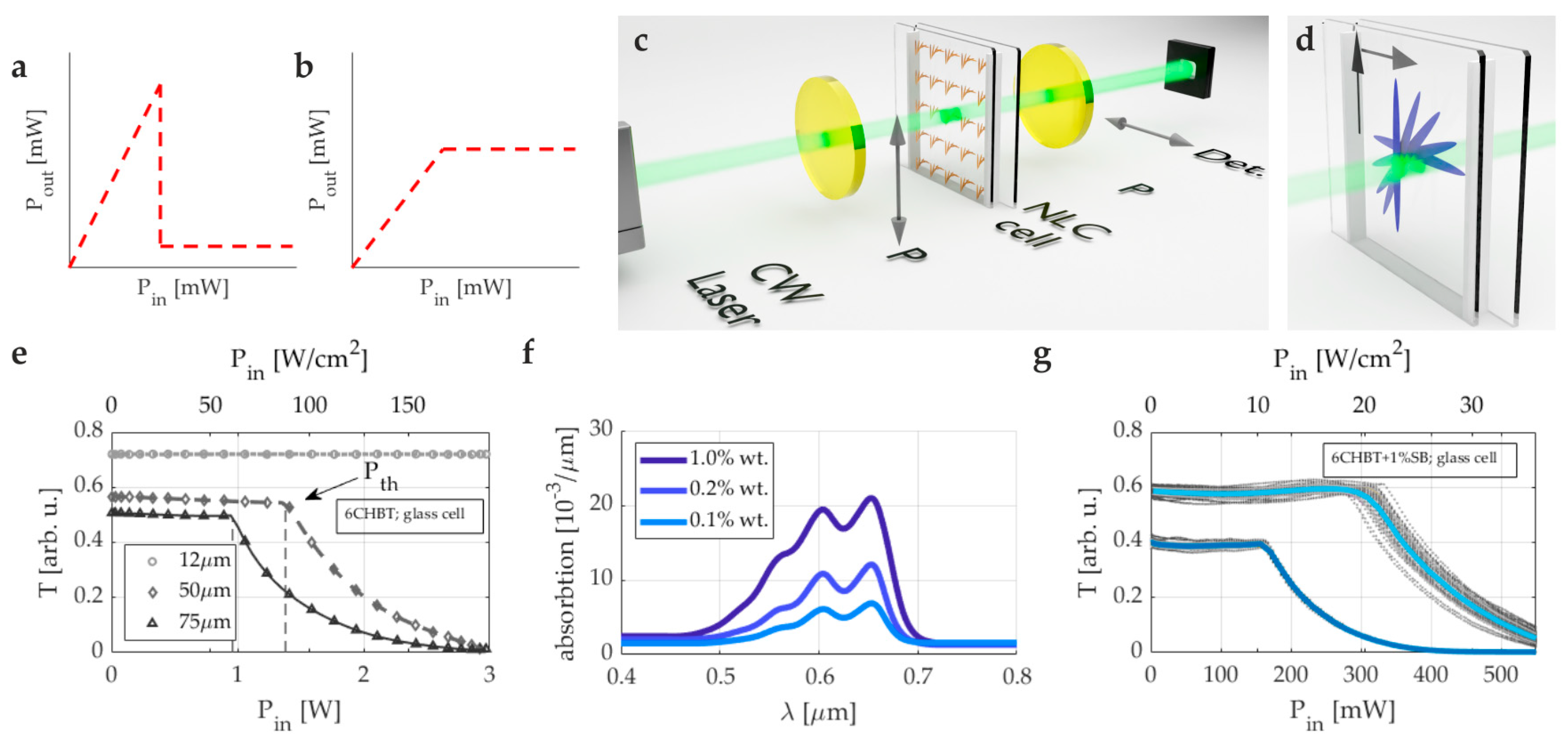
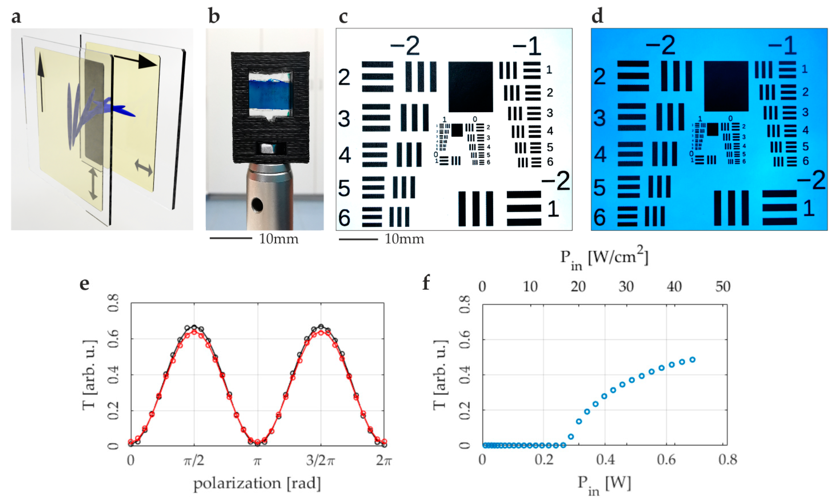
3.1. The Liquid Crystal Cells with Integrated Thin-Film Polarizers

Based on the results presented thus far, demonstrating that thermal effects significantly lower the threshold power, in this section, we propose the implementation of a TN LC cell with integrated plastic polarizers. The film polarizers were used as the boundary layer for the liquid crystal film and were glued to the inner surfaces of the realized NLC cell. This configuration enhances the efficiency of the optical power limiter by further reducing the threshold power necessary for operation. Figure 2a illustrates the arrangement of the NLC cell with the integrated thin-film polarizers in a crossed configuration, aligning the molecular orientation with the optical axes of the polarizers. This strategic integration ensures optimal polarization control, which is critical for the effective modulation of light transmission through the device.
Film polarizers are made of soft plastic, which allows for a simple scratching of the surface using mechanical methods to form an alignment layer for liquid crystal on the polarizer’s surface. For the practical realization of the rubbing process, we used a typical process necessary for creating an alignment layer on glass substrates coated with polyimide. Film polarizers are designed to polarize low-power light beams linearly and can be easily adjusted to custom dimensions to fit the specified cell sizes. The polarizing material is designed and optimized for use within the 500 nm ÷ 700 nm wavelength range, providing an extinction ratio of over 1000:1. To control the thickness of the NLC cells, we used glass spacers (microspheres or microrods) sprayed over the polarizer’s surface prior to the final assembly of the two substrates. The density of spacer deposition was approximately a few pieces per square millimeter. In the absence of liquid crystal within the cell, a darkened image is observed due to a crossed polarizer arrangement. When filled with NLC media, the image becomes brighter, similar to using an external polarizer setup, as shown in Figure 1c. The practical realization of the 12 um liquid crystal cell integrated with thin-film polarizers as in Figure 2a, filled with 6CHBT NLC + 1% SBII w/w, housed in a plastic holder, is shown in Figure 2b. The size of the liquid crystal area is 7 mm × 7 mm.
Since the foil-type polarizers may slightly diffuse the transmitted beam, we first check the imaging quality when such an NLC optical power limiter is combined with an imaging system. The configuration setup was established using a typical CCD camera (DCU223C, Thorlabs), an imaging objective, and an analyzed NLC cell placed in front of the imaging objective. To evaluate the results, we utilized the 1951 USAF resolution test target that was imaged with a CCD camera and objective under white light illumination, as presented in Figure 2c. The same scene was photographed under the same conditions with an additional NLC device (6CHBT NLC + 1% SBII w/w, TN-cell with integrated foil polarizers, thickness equal to 12 μm) placed between the objective and a photographed resolution test, as can be seen in Figure 2d. The overall image remained clearly visible without any noticeable loss in quality. The blue color results from the absorption spectrum of the SBII dye, in our opinion, does not pose a problem as the color balance can be corrected through software during the image processing stage. The entire field of view appeared uniformly bright, with minor deviations in the center-right (brighter) and upper-left (darker) parts. These slight variations in brightness may be attributed to the inhomogeneity of the thickness of the liquid crystal layer, possibly due to the unevenness of the film polarizers’ thickness.
To verify the accuracy of the NLC cell with integrated film polarizers, we also performed transmission measurements, shown in Figure 2e, for a typical TN-textured NLC thick cell (50 μm width and 6CHBT NLC, represented by red circles) placed between crossed dichroic economy film polarizers (of similar quality to film polarizers integrated into a complex TN cell) and for an analogous cell of the same texture and thickness with internal integrated film polarizers (black circles). Both datasets align closely with theoretical projections (represented by solid lines derived from a Mallus formula), demonstrating complete obscuring of the transmitted linearly polarized beam when the initial polarization is perpendicular to the first polarizer’s optical axis. The attenuation observed in the analyzed NLC structures containing pure 6CHBT NLC primarily arises from the transmission characteristics of the polarizer material, with the transmission level at 532 nm wavelength slightly exceeding 80% for a single polarizer. Consequently, the maximum transmission of a dual polarizer in a parallel arrangement is limited to approximately 65%.
One of the last issues requiring attention was the power range of plastic polarizers without incurring damage. To investigate this, we illuminated the single-foil polarizer with a beam of approximately 2 mm width and linear polarization orthogonal to its optical axis and monitored the power of the beam at the output. Under ideal conditions, the transmission should be zero; damage is indicated by any transmission above zero. As can be seen in Figure 2f, the polarizer works properly up to a power of about 240 mW, at which point the transmission rapidly goes above zero. Therefore, a liquid crystal power limiter can handle up to 200 mW at 2 mm diameter, corresponding to a radiation intensity of 13 W/cm2.

3.2. The Performance of Liquid Crystal Optical Power Limiter with Integrated Thin-Film Polarizers

In further developing our optical power limiter that employs both pure and dye-doped NLC, we have optimized the device’s functionality by directly incorporating plastic polarizers with the twisted nematic NLC cell. This modification has streamlined the device’s overall structure, obviating the need for external polarizers. Plastic polarizers were selected due to their thermal conductivity, which is essential to the device’s performance. We have already demonstrated that dye-doped NLC can effectively lower the polarization switching threshold and enhance optical limiting by modulating the order parameter through laser-induced heating. As previously stated, the heating causes a reduction in birefringence, which nearly disappears with high laser exposure. This inhibits the polarization rotation process and decreases transmission. The key benefit of using plastic polarizers is their ability to cause a faster and more significant temperature change within the NLC layer. This change directly influences the liquid crystals’ refractive properties by further reducing birefringence in response to optical intensity. Consequently, the threshold power required for effective optical limiting is substantially lowered, making the device more efficient and responsive in practical applications. A polarizer that absorbs light and has varying thermal conductivities and damage thresholds may be chosen to optimize the trade-off between switching power and/or switching time, depending on the application’s specific requirements.
The TN NLC cells with two internal, crossed plastic film polarizers were prepared, and their transmission characteristics were checked for 12 μm and 30 μm thick cells in pure 6CHBT NLC and 6CHBT doped with 1% w/w of SBII dye. The experimental results are summarized in Figure 3. For the pure 6CHBT NLC (Figure 3a), we observed that the threshold power for the 12 μm and 30 μm TN cells was significantly lower than for typical glass cells, as the transmission characteristics dropped rapidly at powers of about 155 mW and 80 mW, respectively. For the doped NLC with an increased value of linear absorption (Figure 3b), we observed a further reduction in the threshold power, depending on the cell thickness. The NLC optical power limiter activated at 80 mW and 40 mW, which was observed for the cells with a thickness of 12 μm (black circles) and 30 μm (brown squares). The absorbent dopant, combined with additional cell insulation in the form of plastic polarizers, significantly reduced the threshold power. However, this came at the expense of increased attenuation of the optical power limiter in the power range below the activation value. Compared to pure NLC, the transmission of dye-doped NLC cells with foil film polarizers was reduced by approximately 25% for the 12 μm cell and about 40% for the 30 μm cell. However, software compensation could offset the lower transmission level after adequately configuring the final NLC optical limiter device.
The experimental results for the performance of the investigated NLC optical power limiters with foil polarizers at different ambient temperatures were determined for cells of a thickness of 12 μm and 30 μm. The transmission characteristics are illustrated in Figure 3c and Figure 3d, respectively. According to the collected data, the threshold power exhibits a considerable decrease with an increase in temperature, which aligns with the theoretical concept of order parameter modification. This phenomenon is further enhanced by the birefringence modification resulting from thermal effects. The findings revealed in Figure 3 indicate a trade-off between transmittance and the Pth value.

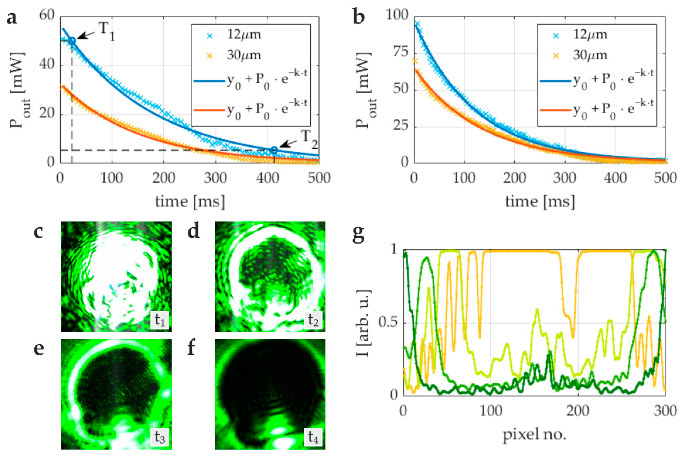
3.3. Turn-On Time and Response Time

The effectiveness of the proposed device is greatly dependent on its response time, a key factor that holds significant importance in the context of limiting optical radiation exposure to levels safe for shielded devices. To measure the response time, we used an experimental setup depicted in Figure 1c, with a photodiode and an oscilloscope to evaluate the temporal switching behavior. The measurements were performed for the 6CHBT NLC doped with 1% SBII w/w and NLC cells of 12 μm and 30 μm thickness with integrated foil film polarizers. As a light source, we used a polarized CW laser beam (aligned with the optical axis of the initial polarizer of the NLC power limiter) at a wavelength of λ = 532 nm and a diameter of roughly 2 mm. The dynamic response of the optical system to laser powers of 100 mW and 200 mW is illustrated in Figure 4a and Figure 4b, respectively. These plots depict the decay of the transmitted power, adhering to an exponential model P 0 · exp k t + y 0 , where P0 [mW], k [1/ms], and y0 [mW] are fit coefficients.
We identified two critical parameters that characterize the temporal behavior of the proposed device: (1) the turn-on time, defined as the duration until a 10% reduction in transmitted power is observed; (2) the response time, defined as the period until a 90% reduction in transmittance is achieved, denoted as T1 and T2, respectively, as shown in Figure 4a. These response times, summarized in Table 1, characterize the capability of the device to quickly mitigate excessive optical radiation and ensure the protection of sensitive components.
The turn-on time of the NLC optical power limiter, regardless of the optical beam power and cell thickness, is typically in the range of tens of milliseconds, while the response time is in the range of hundreds of milliseconds. This may be sufficient for certain applications.
Figure 4c–f show the images of the laser beam directed straight onto a CCD camera and illustrate the impact of the NLC optical power limiter positioned in front of the imaging objective at different time points: t1 ≈ 0 ms, t2 = 67 ms, t3 = 200 ms, and t4 = 470 ms, with a constant exposure time. Initially, the central area of the image in Figure 4c is highly overexposed, and as time progresses, with the beam getting more attenuated, the central part of the image darkens completely, as demonstrated in Figure 4d–f. The normalized intensities along the x-axis, at the mid-height of the images, corresponding to the images in Figure 4c–f, at successive timeframes t1, t2, t3, and t4, are plotted in Figure 4g, represented by solid lines ranging from orange to dark green.

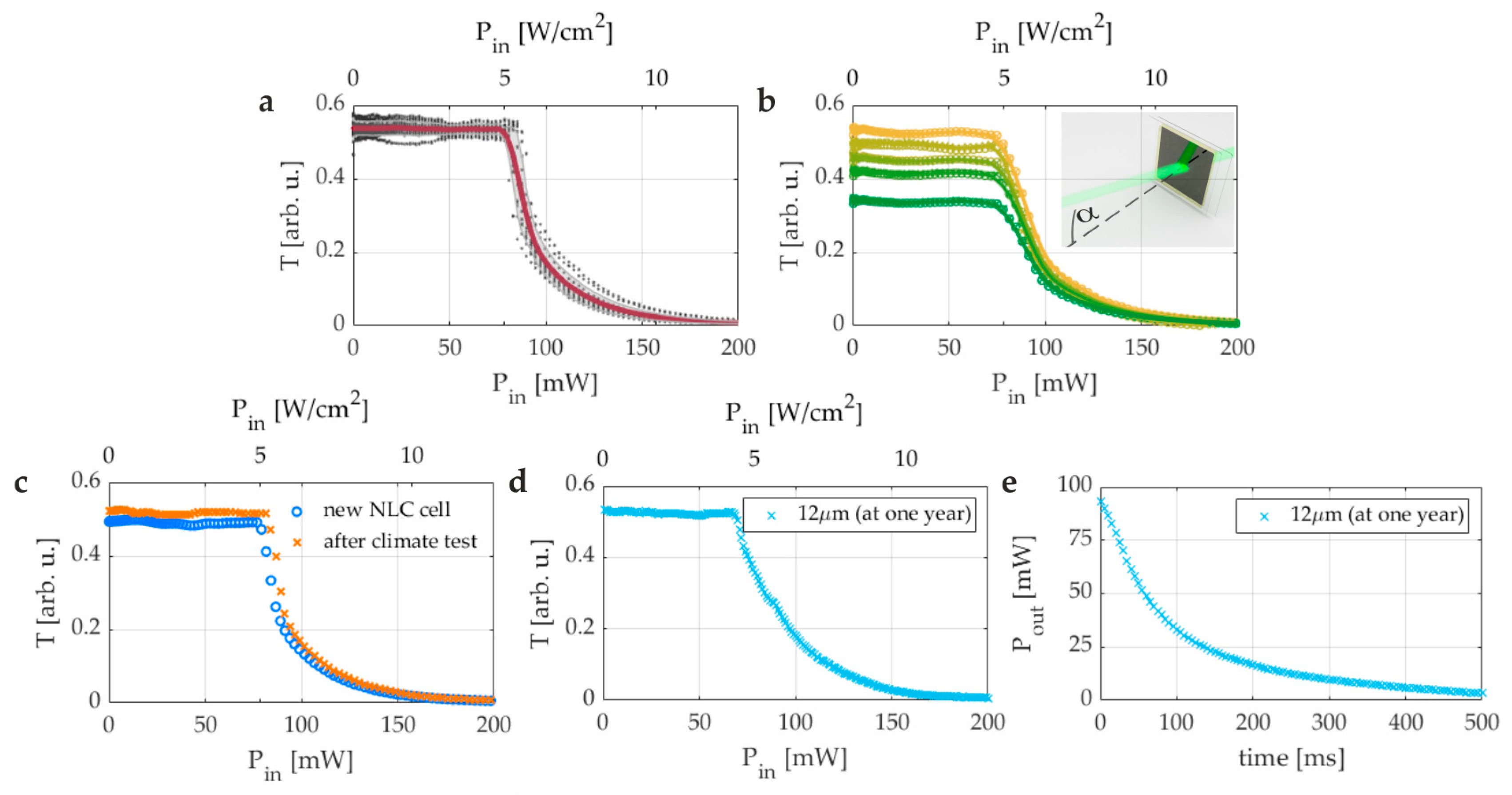
3.4. Repeatability, Field of View, and Climate Tests

In order to thoroughly assess the repeatability, reliability, and stability of the suggested optical power limiter for optoelectronic devices (e.g., photodetectors and/or digital cameras), a set of 24 nematic liquid crystal (NLC) cells with a twisted nematic (TN) configuration and internal plastic polarizers arranged in a crossed alignment were prepared. Each cell had a uniform thickness of 12 µm. Measurements were performed for 6CHBT NLC doped with 1% SBII w/w. The results depicted in Figure 5a exhibit high reproducibility in optical performance. Transmittance measurements performed on the entire series show excellent repeatability, with the mean transmittance value (below the threshold power) at the level of 54% with a notably low standard deviation of under 2% throughout a power range of 0 to 200 mW. These results confirm the device’s consistency and emphasize the effectiveness of the proposed NLC TN configuration in providing reliable protection across various samples.
To determine the effectiveness of the proposed optical power limiter, it is important to test its ability to function well at various angles of the laser beam. We conducted tests to evaluate the angular tolerance of the device by measuring light transmittance at different angles of incidence. This helped us determine the sensitivity of the device to the angle of incidence of the laser beam. The main results obtained and the definition of the angle of incidence (AOI) of the beam are shown in Figure 5b. The successive data sets correspond to the AOI of α = 0°, α = 10°, α = 20°, α = 25°, and α = 30°, yellow to green markers in Figure 5b, respectively. In this experiment, a liquid crystal cell was analyzed by exposing it to a light beam at different angles of incidence (AOIs). The beam was first directed at a normal incidence angle, represented by α = 0°, and the average transmittance for the beam power below the threshold value was approximately 55%. This study showed that the threshold power levels remained constant across all angles tested, confirming the device’s stable performance. However, we noted some variations in the transmission coefficient: it remained within 45% to 55% for AOIs between 0° and 20°, then decreased to approximately 35% at an AOI of 30°. Nevertheless, the results of this study demonstrate the device’s ability to maintain optimal performance under various operational conditions, a critical factor for its usefulness in situations where laser beams may not always be directed at a perpendicular angle.
In order to investigate how high temperature affects the NLC power limiter’s performance, we placed the NLC cell (which included foil polarizers and 6CHBT NLC + 1% SBII w/w) in a climate chamber with simulated environmental conditions for one hour. The temperature was increased to +70 °C, while the humidity was maintained at 50%. After completing the cycle, the sample was removed from the climate chamber and tested for its transmittance characteristics (Figure 5c). In the same way, we also tested the effect of a low temperature (−5 °C) and high and low humidity (10% and 80%, at room temperature), and the obtained results were close to the one presented in Figure 5c (for a high temperature). The condition tests indicate that any variations in the parameters are noticeable up to 30 min after the sample is taken out of the climate chamber. After that, the operating parameters of the NLC device stabilize and remain consistent with the initial level. This suggests that there is no significant impact on the OPL parameters due to changes in temperature over time. The devices were re-evaluated over the course of a year to confirm long-term functionality and durability, indicating that the OPL maintains its original performance. Figure 5d shows the light transmission versus the optical power (intensity) of the incident beam on the OPL (12 μm cell thickness, 6CHBT NLC + 1% SBII w/w), re-measured after a period of more than one year, which almost perfectly matches the characteristic of freshly fabricated NLC cells shown in Figure 5e. It is essential to ensure that the liquid-crystal cells are adequately sealed in order to prevent the NLC medium from degrading over time. No aggregation of SBII dye molecules has been observed over an extended period. The NLC cells maintain a consistent blue color due to the absorption spectrum of Sudan Blue II.
During the final phase of our research, we conducted a crucial experiment to demonstrate the practical value of our NLC TN optical power limiter, which features integrated plastic polarizers. The experiment was designed to simulate real-world scenarios and evaluate the performance of the device under these conditions. The experimental setup is shown in Figure 6a,b, and it aimed to replicate the actual usage conditions of the device. For this experiment, a CCD camera equipped with an objective lens was utilized to image an object featuring a central aperture, allowing a laser beam to pass through and strike the camera directly at normal incidence. This setup is illustrated in Figure 6c with auto-exposure settings capturing the direct impact of the beam on the camera.
A continuous-wave (CW) laser with a wavelength of 532 nm and power output of 200 mW served as the light source, combined with our designed NLC optical power limiter, which includes internal foil polarizers and dye-doped NLC (6CHBT + 1% SBII w/w). Initially, without the protective device, the intense laser exposure led to significant overexposure in the captured images (Figure 6d), causing the camera to malfunction or even be permanently damaged. However, with the optical power limiter in place, the images showed only partial saturation at the center while maintaining excellent visibility around the periphery. The successive images in Figure 6e–g, taken at t1 < 30 ms, t2 = 67 ms, and t3 = 350 ms, document the progressive improvement in the visibility of the object. At the time t3, which exceeds the device’s response time, the center of the image displayed a minimal oversaturated spot, with the majority of the field remaining clear and detailed.
This test effectively demonstrates the capability of the proposed NLC TN-based optical power limiter to provide substantial protection for CCD cameras against high-intensity laser beams. This confirms its operational efficacy in scenarios that closely resemble potential real-life applications.

4. Conclusions

The development of the dye-doped nematic liquid crystal (NLC) optical power limiter (OPL) presented in this study marks a significant advancement in protective technologies for CCDs against high-intensity light exposure. This innovative approach, employing a twisted nematic cell configuration with integrated polarizers, capitalizes on the synergistic effects of reorientational and thermal nonlinearities inherent in NLCs. The results unequivocally demonstrate that the device is effective in modulating the transmission of intense light and efficient in its responsiveness across different light intensities, particularly in the visible spectrum, where CCD cameras are most vulnerable. A pivotal finding of our investigation is the ability of the NLC-based OPL to operate without external electric fields, a common requirement in traditional electro-optical systems. This feature significantly simplifies the system architecture, reducing potential failure and maintenance points, thus enhancing reliability and durability in demanding operational environments such as military and aviation applications. Using green light in our experiments further aligns this study with real-world applications, where the peak sensitivity of CCDs to this wavelength amplifies the risk of damage and operational disruption.
Moreover, the successful integration of absorbing plastic sheet polarizers not only contributed to a substantial reduction in the threshold power necessary for activation but also proved critical in fine-tuning the device’s optical properties to achieve optimal performance. This aspect of our research underscores the potential for scaling the technology to accommodate a range of wavelengths, suggesting broader applications beyond those demonstrated. In a linear regime (low input intensities), we observe the transmission in a range from 30% to 60%. Using an unfocused laser beam, the switch-off power is as low as 60 mW ÷ 120 mW depending on the NLC material and dye, which is at least one tenth of the value for the undoped TN sample without absorbing polarizers. The response time of the proposed structure is about several tens of milliseconds, while the turn-on time is less than 20 milliseconds. The optical structure demonstrated operates without the need for an external power source and effectively protects the CCDs from the intense optical beam in an angle of incidence range as wide as ±30°. Furthermore, the long-term operational reliability of the proposed NLC optical power limiters has been verified over a period of one year. This has revealed that the operational properties are in excellent agreement with the freshly prepared NLC samples. The current technology for NLC-based optical devices, such as LCD displays, is well established and offers numerous advantages for implementing the proposed solution. It is also pertinent to highlight that despite the perception that liquid crystal mixtures—a chemical cocktail comprising several organic compounds—may be hazardous, extensive studies conducted by Merck have demonstrated otherwise [56,57]. Liquid crystals found in LCDs, including those that may be utilised in NLC OPL, are non-hazardous and do not present an unreasonable risk to human health or the environment.
To conclude, the dye-doped NLC OPL developed through this study represents a transformative step forward in optical limiting technologies. By leveraging the unique properties of liquid crystals, enhanced through selective dye doping and innovative design, this solution offers a promising pathway to protecting sensitive optical components against the ever-increasing threat posed by intense light sources. The potential for extensive applications of this technology is vast, with future research exploring its integration into a more comprehensive array of optical systems, potentially expanding its applicability across various sectors reliant on sensitive imaging equipment.

Author Contributions

B.W.K.: methodology, conceptualization, experimental investigation, data curation, validation; M.K.: methodology, experimental investigation, data curation, sample preparation, writing—original draft; M.A.K.: conceptualization, methodology, supervision, funding acquisition; U.A.L.: conceptualization, methodology, experimental investigation, validation, supervision, writing—review and editing. All authors have read and agreed to the published version of the manuscript.

Funding

This research was funded by The National Centre for Research and Development, grant number DOB-1-6/1/PS/2014.

Institutional Review Board Statement

Not applicable.

Informed Consent Statement

Not applicable.

Data Availability Statement

The raw data supporting the conclusions of this article will be made available by the authors on request.

Conflicts of Interest

The authors declare no conflicts of interest.

References

  1. Svensson, S.; Björkert, S.; Kariis, H.; Lopes, C. Countering Laser Pointer Threats to Road Safety. In Optics and Photonics for Counterterrorism and Crime Fighting II; Lewis, C., Owen, G.P., Eds.; SPIE: Stockholm, Sweden, 2006; p. 640207. [Google Scholar]
  2. Webb, C.; Jones, J.D.C. (Eds.) Handbook of Laser Technology and Applications; CRC Press: Boca Raton, FL, USA, 2020; ISBN 978-1-4822-4077-1. [Google Scholar]
  3. Peng, F.; Lee, Y.-H.; Luo, Z.; Wu, S.-T. Low Voltage Blue Phase Liquid Crystal for Spatial Light Modulators. Opt. Lett. 2015, 40, 5097. [Google Scholar] [CrossRef] [PubMed]
  4. Ritt, G.; Eberle, B. Sensor Protection against Laser Dazzling; Huckridge, D.A., Ebert, R.R., Eds.; SPIE: Toulouse, France, 2010; p. 783404. [Google Scholar]
  5. Savage, N. Digital Spatial Light Modulators. Nat. Photon. 2009, 3, 170–172. [Google Scholar] [CrossRef]
  6. Xie, H.; Wang, L.; Wang, H.; Zou, C.; Wang, M.; Wang, B.; Chen, Z.; Zhang, L.; Zhang, X.; Yang, Z.; et al. Electrically Tunable Properties of Wideband-Absorptive and Reflection-Selective Films Based on Multi-Dichroic Dye-Doped Cholesteric Liquid Crystals. Liq. Cryst. 2015, 42, 1698–1705. [Google Scholar] [CrossRef]
  7. Yang, D.-K.; Wu, S.-T. Fundamentals of Liquid Crystal Devices; Wiley SID Series in Display Technology; John Wiley: Chichester, UK; Hoboken, NJ, USA, 2006; ISBN 978-0-470-01542-1. [Google Scholar]
  8. Dini, D.; Calvete, M.J.F.; Hanack, M. Nonlinear Optical Materials for the Smart Filtering of Optical Radiation. Chem. Rev. 2016, 116, 13043–13233. [Google Scholar] [CrossRef]
  9. Tutt, L.W.; Boggess, T.F. A Review of Optical Limiting Mechanisms and Devices Using Organics, Fullerenes, Semiconductors and Other Materials. Prog. Quantum Electron. 1993, 17, 299–338. [Google Scholar] [CrossRef]
  10. He, G.S.; Lin, T.-C.; Prasad, P.N.; Cho, C.-C.; Yu, L.-J. Optical Power Limiting and Stabilization Using a Two-Photon Absorbing Neat Liquid Crystal in Isotropic Phase. Appl. Phys. Lett. 2003, 82, 4717–4719. [Google Scholar] [CrossRef]
  11. Wang, J.; Blau, W.J. Inorganic and Hybrid Nanostructures for Optical Limiting. J. Opt. A Pure Appl. Opt. 2009, 11, 024001. [Google Scholar] [CrossRef]
  12. Khoo, I.C.; Wood, M.; Shih, M.Y.; Chen, P. Extremely Nonlinear Photosensitive Liquid Crystals for Image Sensing and Sensor Protection. Opt. Express 1999, 4, 432–442. [Google Scholar] [CrossRef]
  13. Morel, Y.; Irimia, A.; Najechalski, P.; Kervella, Y.; Stephan, O.; Baldeck, P.L.; Andraud, C. Two-Photon Absorption and Optical Power Limiting of Bifluorene Molecule. J. Chem. Phys. 2001, 114, 5391–5396. [Google Scholar] [CrossRef]
  14. Li, C.; Yang, K.; Feng, Y.; Su, X.; Yang, J.; Jin, X.; Shui, M.; Wang, Y.; Zhang, X.; Song, Y.; et al. Investigation of Two-Photon Absorption Induced Excited State Absorption in a Fluorenyl-Based Chromophore. J. Phys. Chem. B 2009, 113, 15730–15733. [Google Scholar] [CrossRef] [PubMed]
  15. Sun, Y.-P.; Riggs, J.E.; Henbest, K.B.; Martin, R.B. Nanomaterials as Optical Limiters. J. Nonlinear Optic. Phys. Mat. 2000, 9, 481–503. [Google Scholar] [CrossRef]
  16. Zhou, G.; Wong, W.; Lin, Z.; Ye, C. White Metallopolyynes for Optical Limiting/Transparency Trade-off Optimization. Angew. Chem. Int. Ed. 2006, 45, 6189–6193. [Google Scholar] [CrossRef] [PubMed]
  17. Zhou, G.-J.; Wong, W.-Y. Organometallic Acetylides of PtII, AuI and HgII as New Generation Optical Power Limiting Materials. Chem. Soc. Rev. 2011, 40, 2541–2566. [Google Scholar] [CrossRef] [PubMed]
  18. O’Flaherty, S.M.; Hold, S.V.; Cook, M.J.; Torres, T.; Chen, Y.; Hanack, M.; Blau, W.J. Molecular Engineering of Peripherally And Axially Modified Phthalocyanines for Optical Limiting and Nonlinear Optics. Adv. Mater. 2003, 15, 19–32. [Google Scholar] [CrossRef]
  19. Senge, M.O.; Fazekas, M.; Notaras, E.G.A.; Blau, W.J.; Zawadzka, M.; Locos, O.B.; Ni Mhuircheartaigh, E.M. Nonlinear Optical Properties of Porphyrins. Adv. Mater. 2007, 19, 2737–2774. [Google Scholar] [CrossRef]
  20. Bao, Q.; Zhang, H.; Wang, Y.; Ni, Z.; Yan, Y.; Shen, Z.X.; Loh, K.P.; Tang, D.Y. Atomic-Layer Graphene as a Saturable Absorber for Ultrafast Pulsed Lasers. Adv. Funct. Mater. 2009, 19, 3077–3083. [Google Scholar] [CrossRef]
  21. Chen, Y.; Lin, Y.; Liu, Y.; Doyle, J.; He, N.; Zhuang, X.; Bai, J.; Blau, W.J. Carbon Nanotube-Based Functional Materials for Optical Limiting. J. Nanosci. Nanotechnol. 2007, 7, 1268–1283. [Google Scholar] [CrossRef] [PubMed]
  22. Qian, H.; Li, S.; Li, Y.; Chen, C.-F.; Chen, W.; Bopp, S.E.; Lee, Y.U.; Xiong, W.; Liu, Z. Nanoscale Optical Pulse Limiter Enabled by Refractory Metallic Quantum Wells. Sci. Adv. 2020, 6, eaay3456. [Google Scholar] [CrossRef]
  23. Li, C.; Peng, X.; Liu, M.; Song, M.; Li, D. Optical Limiting Property of Gold Nanorods/Silicone Hybrid Materials to Tunable Laser. J. Lumin. 2016, 177, 88–92. [Google Scholar] [CrossRef]
  24. Li, C.; Liu, M.; Yan, L.; Liu, N.; Li, D.; Liu, J.; Wang, X. Silver Nanoparticles/Polydimethylsiloxane Hybrid Materials and Their Optical Limiting Property. J. Lumin. 2017, 190, 1–5. [Google Scholar] [CrossRef]
  25. Varma, S.J.; Kumar, J.; Liu, Y.; Layne, K.; Wu, J.; Liang, C.; Nakanishi, Y.; Aliyan, A.; Yang, W.; Ajayan, P.M.; et al. 2D TiS2 Layers: A Superior Nonlinear Optical Limiting Material. Adv. Opt. Mater. 2017, 5, 1700713. [Google Scholar] [CrossRef]
  26. Guo, Z.; Du, F.; Ren, D.; Chen, Y.; Zheng, J.; Liu, Z.; Tian, J. Covalently Porphyrin-Functionalized Single-Walled Carbon Nanotubes: A Novel Photoactive and Optical Limiting Donor–Acceptor Nanohybrid. J. Mater. Chem. 2006, 16, 3021–3030. [Google Scholar] [CrossRef]
  27. Vivas, M.G.; De Boni, L.; Cooper, T.M.; Mendonca, C.R. Interpreting Strong Two-Photon Absorption of PE3 Platinum Acetylide Complex: Double Resonance and Excited State Absorption. ACS Photonics 2014, 1, 106–113. [Google Scholar] [CrossRef]
  28. Vivas, M.G.; De Boni, L.; Cooper, T.M.; Mendonca, C.R. Understanding the Two-Photon Absorption Spectrum of PE2 Platinum Acetylide Complex. J. Phys. Chem. A 2014, 118, 5608–5613. [Google Scholar] [CrossRef] [PubMed]
  29. De La Torre, G.; Vázquez, P.; Agulló-López, F.; Torres, T. Role of Structural Factors in the Nonlinear Optical Properties of Phthalocyanines and Related Compounds. Chem. Rev. 2004, 104, 3723–3750. [Google Scholar] [CrossRef] [PubMed]
  30. Limosani, F.; Tessore, F.; Di Carlo, G.; Forni, A.; Tagliatesta, P. Nonlinear Optical Properties of Porphyrin, Fullerene and Ferrocene Hybrid Materials. Materials 2021, 14, 4404. [Google Scholar] [CrossRef]
  31. Blau, W.J.; Byrne, H.J.; Cardin, D.J.; Dennis, T.J.; Hare, J.P.; Kroto, H.W.; Taylor, R.; Walton, D.R.M. Large Infrared Nonlinear Optical Response of C 60. Phys. Rev. Lett. 1991, 67, 1423–1425. [Google Scholar] [CrossRef]
  32. Wang, L.; Li, Q. Stimuli-Directing Self-Organized 3D Liquid-Crystalline Nanostructures: From Materials Design to Photonic Applications. Adv. Funct. Mater. 2016, 26, 10–28. [Google Scholar] [CrossRef]
  33. Muševič, I. Integrated and Topological Liquid Crystal Photonics. Liq. Cryst. 2014, 41, 418–429. [Google Scholar] [CrossRef]
  34. Johnson, R.V.; Tanguay, A.R. Optical Beam Propagation in Anisotropic Media. In Proceedings of the Annual Meeting Optical Society of America; Optica Publishing Group, Washington, DC, USA, 14–18 October 1985; Optica Publishing Group: Washington, DC, USA, 1985. paper FS1. [Google Scholar]
  35. Li, Q. (Ed.) Liquid Crystals Beyond Displays: Chemistry, Physics, and Applications, 1st ed.; Wiley: Hoboken, NJ, USA, 2012; ISBN 978-1-118-07861-7. [Google Scholar]
  36. Schadt, M. Nematic Liquid Crystals and Twisted-Nematic LCDs. Liq. Cryst. 2015, 42, 646–652. [Google Scholar] [CrossRef]
  37. Khoo, I.C. Nonlinear Optics of Liquid Crystalline Materials. Phys. Rep. 2009, 471, 221–267. [Google Scholar] [CrossRef]
  38. Khoo, I.-C.; Wu, S.-T. Optics and Nonlinear Optics of Liquid Crystals; Series in Nonlinear Optics; World Scientific: Singapore, 1993; ISBN 978-981-02-0935-3. [Google Scholar]
  39. Khoo, I.C. Nonlinear Optics, Active Plasmonics and Metamaterials with Liquid Crystals. Prog. Quantum Electron. 2014, 38, 77–117. [Google Scholar] [CrossRef]
  40. Wang, L. Self-Activating Liquid Crystal Devices for Smart Laser Protection. Liq. Cryst. 2016, 43, 2062–2078. [Google Scholar] [CrossRef]
  41. Usui, K.; Matsumoto, K.; Katayama, E.; Akamatsu, N.; Shishido, A. A Deformable Low-Threshold Optical Limiter with Oligothiophene-Doped Liquid Crystals. ACS Appl. Mater. Interfaces 2021, 13, 23049–23056. [Google Scholar] [CrossRef]
  42. Zhang, R.; Zhang, Z.; Han, J.; Yang, L.; Li, J.; Song, Z.; Wang, T.; Zhu, J. Advanced Liquid Crystal-Based Switchable Optical Devices for Light Protection Applications: Principles and Strategies. Light Sci. Appl. 2023, 12, 11. [Google Scholar] [CrossRef] [PubMed]
  43. Khoo, I.C.; Park, J.-H.; Liou, J. All-Optical Switching of Continuous Wave, Microsecond Lasers with a Dye-Doped Nematic Liquid Crystal. Appl. Phys. Lett. 2007, 90, 151107. [Google Scholar] [CrossRef]
  44. Sheng, C.; Norwood, R.A.; Wang, J.; Thomas, J.; Steeves, D.; Kimball, B.; Peyghambarian, N. Nonlinear Optical Transmission of Lead Phthalocyanine-Doped Nematic Liquid Crystal Composites for Multiscale Nonlinear Switching from Nanosecond to Continuous Wave. Appl. Opt. 2009, 48, 2731–2734. [Google Scholar] [CrossRef]
  45. Khoo, I.-C.; Park, J.-H.; Liou, J.D. Theory and Experimental Studies of All-Optical Transmission Switching in a Twist-Alignment Dye-Doped Nematic Liquid Crystal. J. Opt. Soc. Am. B 2008, 25, 1931–1937. [Google Scholar] [CrossRef]
  46. Thomas, R.J.; Rockwell, B.A.; Marshall, W.J.; Aldrich, R.C.; Zimmerman, S.A.; Rockwell, R.J. A Procedure for Laser Hazard Classification under the Z136.1-2000 American National Standard for Safe Use of Lasers. J. Laser Appl. 2002, 14, 57–66. [Google Scholar] [CrossRef]
  47. Thomas, R.J.; Rockwell, B.A.; Marshall, W.J.; Aldrich, R.C.; Zimmerman, S.A.; Rockwell, R.J. A Procedure for Multiple-Pulse Maximum Permissible Exposure Determination under the Z136.1-2000 American National Standard for Safe Use of Lasers. J. Laser Appl. 2001, 13, 134–140. [Google Scholar] [CrossRef]
  48. Dabrowski, R.; Dziaduszek, J.; Szczuciński, T. Mesomorphic Characteristics of Some New Homologous Series with the Isothiocyanato Terminal Group. Mol. Cryst. Liq. Cryst. 1985, 124, 241–257. [Google Scholar] [CrossRef]
  49. Dabrowski, R.; Dziaduszek, J.; Szczucinskl, T. 4-/Trans-4′-n-Alkylcyclohezxyl/Isothiocyanatobenzenes a New Class of Low-Melting Stable Nematics. Mol. Cryst. Liq. Cryst. 1984, 102, 155–160. [Google Scholar] [CrossRef]
  50. Self, R.H.; Please, C.P.; Sluckin, T.J. Deformation of Nematic Liquid Crystals in an Electric Field. Eur. J. Appl. Math. 2002, 13, 1–23. [Google Scholar] [CrossRef]
  51. Durbin, S.D.; Arakelian, S.M.; Shen, Y.R. Optical-Field-Induced Birefringence and Freedericksz Transition in a Nematic Liquid Crystal. Phys. Rev. Lett. 1981, 47, 1411–1414. [Google Scholar] [CrossRef]
  52. Alberucci, A.; Laudyn, U.A.; Piccardi, A.; Kwasny, M.; Klus, B.; Karpierz, M.A.; Assanto, G. Nonlinear Continuous-Wave Optical Propagation in Nematic Liquid Crystals: Interplay between Reorientational and Thermal Effects. Phys. Rev. E 2017, 96, 012703. [Google Scholar] [CrossRef] [PubMed]
  53. Unsal, Y.E.; Tuzen, M.; Soylak, M. Spectrophotometric Determination of Sudan Blue II in Environmental Samples after Dispersive Liquid-Liquid Microextraction. Quím. Nova 2014, 37, 1128–1131. [Google Scholar] [CrossRef]
  54. Kwaśny, M.; Klus, B.W.; Laudyn, U.A. Dual Role of Beam Polarization and Power in Nematic Liquid Crystals: A Comprehensive Study of TE- and TM-Beam Interactions. Materials 2024, 17, 999. [Google Scholar] [CrossRef]
  55. Kwaśny, M.; Ostromęcka, I.; Klus, B.W.; Laudyn, U.A. Interplay of Reorientational and Thermal Solitons: Unveiling the Dynamic Coexistence and Enhanced Nonlinear Response in Nematic Liquid Crystals. Opt. Mater. Express 2023, 13, 2071–2082. [Google Scholar] [CrossRef]
  56. Chen, J.; Cranton, W.; Fihn, M. (Eds.) Handbook of Visual Display Technology; Springer Reference; Springer: Berlin, Germany, 2012; ISBN 978-3-540-79566-7. [Google Scholar]
  57. Martin, R.; Simon-Hettich, B.; Becker, W. New EU Legislation (WEEE) Compliant Recovery Processes for LCDs. IDW 04 Proc of the 11th IDW: 583-586. Available online: http://www.lcdtvassociation.org/images/Proceeding_New_EU_Legislation_WEEE_Compliant_Recovery_Processes_for_LCDs-Merck_September_2008n.pdf (accessed on 22 May 2024).
Figure 1. The principle of the operation of self-activating laser protection systems: (a) an attenuator/optical switch; (b) a power limiter; (c,d) a sketch of the setup and the geometry of TN-textured NLC cell intended for the experimental investigation of NLC optical power limiters: (from left to right) continuous-wave laser (λ = 532 nm), polarizer (P, 0°), twisted nematic NLC cell, polarizer (P, 90°), detector/CCD camera. (e) Light transmission as a function of the beam power for a TN-textured 6CHBT NLC with a thickness of 12 μm (triangles), 50 μm (diamonds), and 75 μm (circles)—dark to light gray lines, respectively, according to the configuration shown in (c), serve as a visual guide for the eye. (f) A plot of Sudan Blue II absorption versus wavelength for different dye concentrations (w/w): 0.1%, 0.2%, and 1.0% (light to dark blue lines, respectively). (g) Light transmittance as a function of the input beam power for a TN-textured 6CHBT NLC doped with 1% w/w of Sudan Blue II dye: an average value plotted for NLC cells of a thickness 12 μm and 30 μm—light and dark blue lines, respectively. The black dots indicate experimental data for six analyzed cells in 8 different areas, and the shaded regions represent a standard deviation of the mean value.
Applsci 14 04682 g001
Figure 2. (a) The sketch of TN NLC cell with internal foil film polarizers in crossed configuration. The rubbing direction is the same as the optical axis of each polarizer (indicated by the double and single arrows, respectively); (b) The realization of the liquid crystal cell with a thickness of 12 μm integrated with thin-film polarizers as in (a) filled with 6CHBT NLC + 1% SBII w/w, housed in a plastic holder; (c) The 1951 USAF resolution test target imaged with a CCD camera illuminated with white light, and (d) the same target imaged with a CCD camera with an NLC optical power limiter (b) placed in front of the camera lens; (e) Light transmission (λ = 532 nm, P < 1 mW, linear polarization) for TN NLC cells (of a thickness equal 12 μm) filled with 6CHBT NLC + 1% SBII w/w plotted as a function of the polarization angle: experimental results for a typical cell (red circles) and for a cell with integrated film polarizers (black circles) compared to theoretical values (solid lines); (f) Characterization of the durability of thin-film foil polarizers: transmission as a function of the beam power (beam width about 2 mm). The light polarization was perpendicular to the optical axis of a polarizer under test.
Applsci 14 04682 g002
Figure 3. Light transmission as a function of beam power (intensity) at the output of a TN-textured nematic liquid crystal cell with internal film polarizers: experimentally obtained values for (a) pure 6CHBT NLC and cells of 12 μm (black circles) and 30 μm (brown squares) thickness; (b) Corresponding plot to (a) for 6CHBT doped with 1% by weight Sudan Blue II; (c,d) Light transmission obtained at different ambient temperatures: 20 °C, 30 °C, and 40 °C (blue, purple, and red circles) as a function of the beam power: data obtained for TN-textured NLC cells filled with 6CHBT doped with 1% by weight of Sudan Blue II, internal film polarizers and a thickness of (c) 12 μm and (d) 30 μm, analyzed in (b).
Applsci 14 04682 g003
Figure 4. Transmission characteristics of the analyzed TN cells (6CHBT doped with 1% by weight Sudan Blue II) showing the turn-on time T1 and the response time T2 related to the beam of a λ = 532 nm, a diameter 2 mm, and optical power of (a) P = 100 mW; (b) P = 200 mW. The blue and orange markers represent the transmitted power values from the moment the analyzed sample was exposed to laser radiation (at normal incidence), recorded for NLC cells of a thickness of 12 μm (blue crosses) and 30 μm (orange crosses). Solid lines represent the best-fit exponential curves (fit coefficients y0 [mW], P0 [mW], k [1/ms]: (a) 12 μm: y0 = −0.12, P0 = 55.2, k = 0.0056; 30 μm: y0 = 0.21, P0 = 31.7, k = 0.0067; (b) 12 μm: y0 = 0.95, P0 = 94.3, k = 0.0082; 30 μm: y0 = 0.64, P0 = 63.5, k = 0.0076); (cf) The images captured by the CCD camera blinded by the P = 200 mW light beam of a λ = 532 nm, width 2 mm, passing through the NLC optical power limiter. Presented in different timeframes: t1 ≈ 0 ms, t2 = 67 ms, t3 = 200 ms, t4 = 470 ms. The resolution of the images is 300 × 300 pixels; (g) Normalized intensities (x-cut, in the mid-height of images) plotted from images (cf), orange to dark green solid lines, respectively.
Applsci 14 04682 g004
Figure 5. Repeatability and durability tests for the TN cells (6CHBT doped with 1% of SBII w/w, for a cell of thickness d = 12 μm, the light beam of a wavelength λ = 532 nm and a width of about 2 mm): (a) the normalized transmission acquired for 24 samples (black dots) and the average value (brown solid line), plotted as a function of the optical power of a light beam. The gray area indicates the standard deviation of the mean value; (b) Transmission as a function of the angle of incidence of the beam on a liquid crystal cell. The inset shows the geometry of the experimental measurements. Plotted for α = 0°, α = 10°, α = 20°, α = 25°, and α = 30°, yellow to green markers; (c) Effect of the high-temperature conditions on the performance of an NLC optical power limiter. Transmission for a: “freshly fabricated” NLC cell (blue circles) and the same cell kept for 1 h in a climatic chamber (temperature +70 °C, the humidity 50%), measured about 30 min after removing the sample from the climate chamber; (d) Light transmission as a function of beam power (intensity) and (e) transmission versus time characteristics related to the beam of a λ = 532 nm, a diameter of 2 mm, and an optical power of P = 200 mW, re-measured after over one year.
Applsci 14 04682 g005
Figure 6. (a,b) The proposed arrangement of the CCD camera and the NLC power limiter; (c) The object viewed by the camera, with the aperture in the central part of the image (marked by a dotted line), according to the configuration in (a); (d) The image obtained by the CCD camera (fully saturated) when the CCD matrix is directly illuminated with a beam of about 2 mm width, λ = 532 nm, and power of P = 200 mW; (eg) images of the object taken by a CCD camera combined with a liquid crystal optical power limiter, recorded at different moments from beam exposition: t1 < 30 ms, t2 = 67 ms, and t3 = 350 ms.
Applsci 14 04682 g006
Table 1. Response times of nematic liquid crystals optical power limiters with integrated foil film polarizers (NLC: 6CHBT doped with 1% w/w of SBII dye).
Cell ThicknessPin = 100 mWPin = 200 mW
12 μmT1 = 18 ms; T2 = 410 msT1 = 12 ms; T2 = 300 ms
30 μmT1 = 19 ms; T2 = 335 msT1 = 15 ms; T2 = 320 ms
Disclaimer/Publisher’s Note: The statements, opinions and data contained in all publications are solely those of the individual author(s) and contributor(s) and not of MDPI and/or the editor(s). MDPI and/or the editor(s) disclaim responsibility for any injury to people or property resulting from any ideas, methods, instructions or products referred to in the content.

