Article

Practical Test on the Operation of the Three-Phase Induction Motor under Single-Phasing Fault

1
Department of Electrical and Computer Engineering, Faculty of Engineering and Technology, Birzeit University, Birzeit 9730000, Palestine
2
Department of Engineering, Palestine Ahliya University, Bethlehem P1520468, Palestine
3
Department of Mechanical and Mechatronics Engineering, Faculty of Engineering and Technology, Birzeit University, Birzeit 9730000, Palestine
*
Author to whom correspondence should be addressed.
Appl. Sci. 2024, 14(11), 4690; https://doi.org/10.3390/app14114690
Submission received: 19 April 2024 / Revised: 24 May 2024 / Accepted: 25 May 2024 / Published: 29 May 2024
(This article belongs to the Special Issue Fault Diagnosis and Detection of Machinery)

Abstract

:
Single-phasing is a common problem in the three-phase electrical grid. Despite the fact that the fault occurs in one phasing, the three-phase load is affected, and therefore the load is typically turned off. The three-phase induction motor is the most commonly used in the industry; therefore, this research investigates the behavior of the three-phase induction motor under a single-phasing fault. The main aim of this paper is to answer the question, should the three-phase induction motor be turned off under a single-phasing fault? The problem is investigated theoretically and compared with practical tests to explore the parameters of the induction motor (current, stator temperature, and vibration) that are affected under healthy and single-phasing fault conditions. A practical test machine is built to test the motor behavior under single-phasing faults, where the practical experiment results are compared to those of the simulations. Despite the common recommendation under single-phasing fault is to turn off the induction motors, the preliminary results of this study show that turning off an induction motor under single-phasing can be avoided under certain operating conditions with a simple protection scheme, which is useful in some practical situations.

1. Introduction

Three-phase induction motors are widely used in industrial applications due to their low cost, robustness against faults, ease of maintenance, high performance, and high reliability. The robustness of the induction motor makes it the first choice in industrial applications; therefore, out of all the motors used, more than 80% of these motors are induction motors [1]. Despite the high reliability of induction motors, the operating conditions may expose the machine to different fault conditions. These faults may cause industrial production losses if the machine is shut down.
The three-phase induction motor is powered by a three-phase supply; when one of the three phases fails, the condition is known as single-phasing. As a result, single phasing is one of the motor supply’s unbalanced cases. It occurs when one of the three lines is opened due to the following: an equipment failure of the supply system, a downed line, the blown fuse of the utility system, or due to a short circuit in one phase [2]. If the motor continues to operate under single-phasing, higher currents flow through the other lines, the stator temperature increases, and the mechanical vibrations of the motor are also increased.
Once a single-phasing fault occurs while the motor is running, the motor continues to run due to the torque generated by the other two phases, and this torque is produced on demand by the load. As a result, more current flows through the other two lines and more heat is generated in the stator winding resulting in serious damage to the electric motor itself. If a single-phasing fault already perseveres in the supply line, the three-phase induction motor will not start.
A review of the literature reveals various analyses and concerns about electrical faults in induction motors (open-phase, voltage unbalance, overvoltage, and phase short-circuit). The work in [3,4,5,6,7] investigated the effects of voltage imbalance on the torque and current of an induction motor. The research in [8] presented an experimental study on reducing the power rating of an induction motor under different voltage unbalanced conditions and comparing it to the National Electrical Manufacturers Association (NEMA) standard. Other studies focused on the protection of induction motors from single-phasing faults [9]. Two protection methods are presented, the first using traditional electric convertors and the second using AC to DC converters and the Peripheral Interface Controller (PIC). The authors of [10,11] highlighted the motor operation under different load conditions under the single-phasing fault, which could result in severe winding overheating. As a result, considerable attention has been paid to the installation of motor protection devices. The authors discussed the operation of an induction motor under unbalanced voltage and mechanical overload in [12,13]. Overcurrent was the basis for the proposed protection scheme. The single-phasing fault with different fault tolerant control (FTC) algorithms has been reviewed in [14,15,16,17,18,19,20,21]. In [14], the authors proposed a method based on a simple open-switch fault monitoring system that uses a reference voltage vector analysis in the stationary α-β coordinates for failure detection. The authors in [15] proposed a post-fault control strategy for wye-connected three-phase induction motor drives during a single open-phase fault. The proposed direct rotor field-oriented control system is derived from the conventional vector control system with minor modifications. In [16], a vector control strategy based on indirect rotor field-oriented control for star-connected three-phase induction motor drives under open-phase fault using balanced and unbalanced transformation matrices is proposed. The researchers in [17] proposed a method that enables the control of a three-phase IM in the presence of an open-phase failure in one of its phases without the need for control structure changes to the conventional field-oriented control algorithm. The proposed drive system significantly reduces the speed and torque pulsations caused by an open-phase fault in the stator windings. The researchers in [18] presented an investigation of the field-oriented control performance of star-connected three-phase induction motor drives with an open-phase fault. The control system enables it to work in healthy and faulty conditions without requiring any modifications to the conventional control structure, but only in the control parameters. The work in [19] proposed a fault-tolerant model-based torque control strategy for a three-phase permanent magnet synchronous motor with an inter-turn winding short circuit. The cascaded control scheme comprises a continuous control set with a model-predictive control and a subordinate PI controller. The authors in [20] focused on establishing a practical and useful framework for tuning the PI controllers of each direct torque control with a space vector modulation loop applied to a three-phase induction motor.
The recent research on the single-phasing problem concentrates on FTC methods against this problem. In [21], a simple fault-tolerant control method for single-phasing induction motor drives was proposed based on a PI controller. The proposed technique proves the stability of the motor’s operation at low speeds and low torque ripples. In [22], the authors provide an FTC drive system that can be used for the sensorless speed-controlled Y-connected three-phase induction motor during both normal and single-phasing conditions. In [23], the research is focused on fault detection based on the comparison between predicted and actual values of stator currents. In the proposed FTC method, an asymmetrical current transformation is used for stator current components, and the conventional symmetrical voltage transformation is employed for stator voltage components.
It is important to mention here that most of the recent publications on single-phasing fault present algorithms and techniques for fault-tolerant control on three-phase induction motors under single-phasing fault, ignoring the effect of the rising stator winding temperature and ignoring the main recommendation under this fault, which is to turn off the three-phase induction motor. This recommendation is crucial for preventing motor damage and ensuring safety.
This study attempts to answer the question: should the three-phase induction motor be turned off under the single-phasing fault? To do this, the single-phasing fault of the induction motor is presented and investigated theoretically and practically through the following:
  • Analysis of the single-phasing fault and derivation of the electrical model of the three-phase induction motor.
  • Verification of the results obtained under different load conditions.
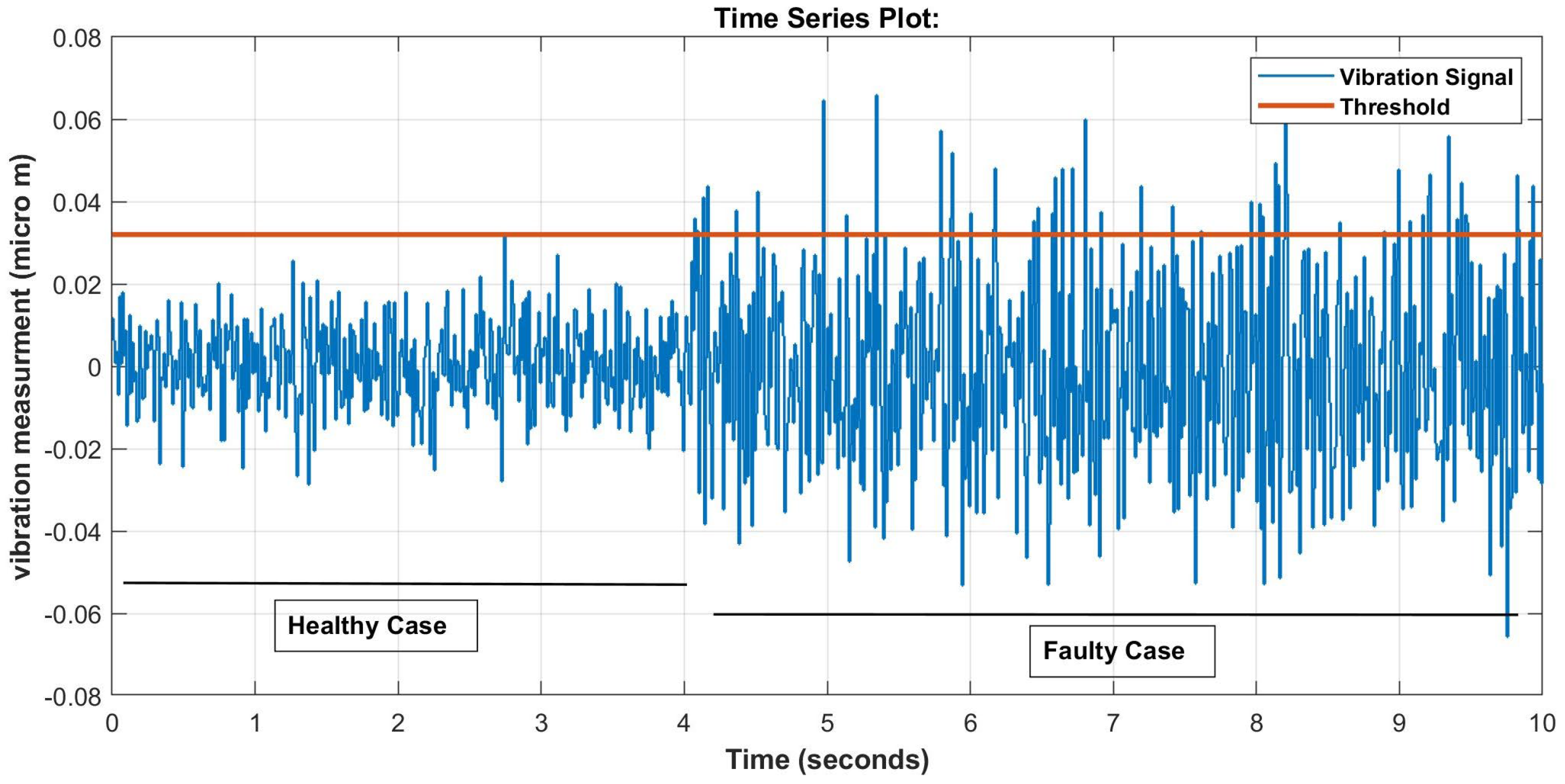
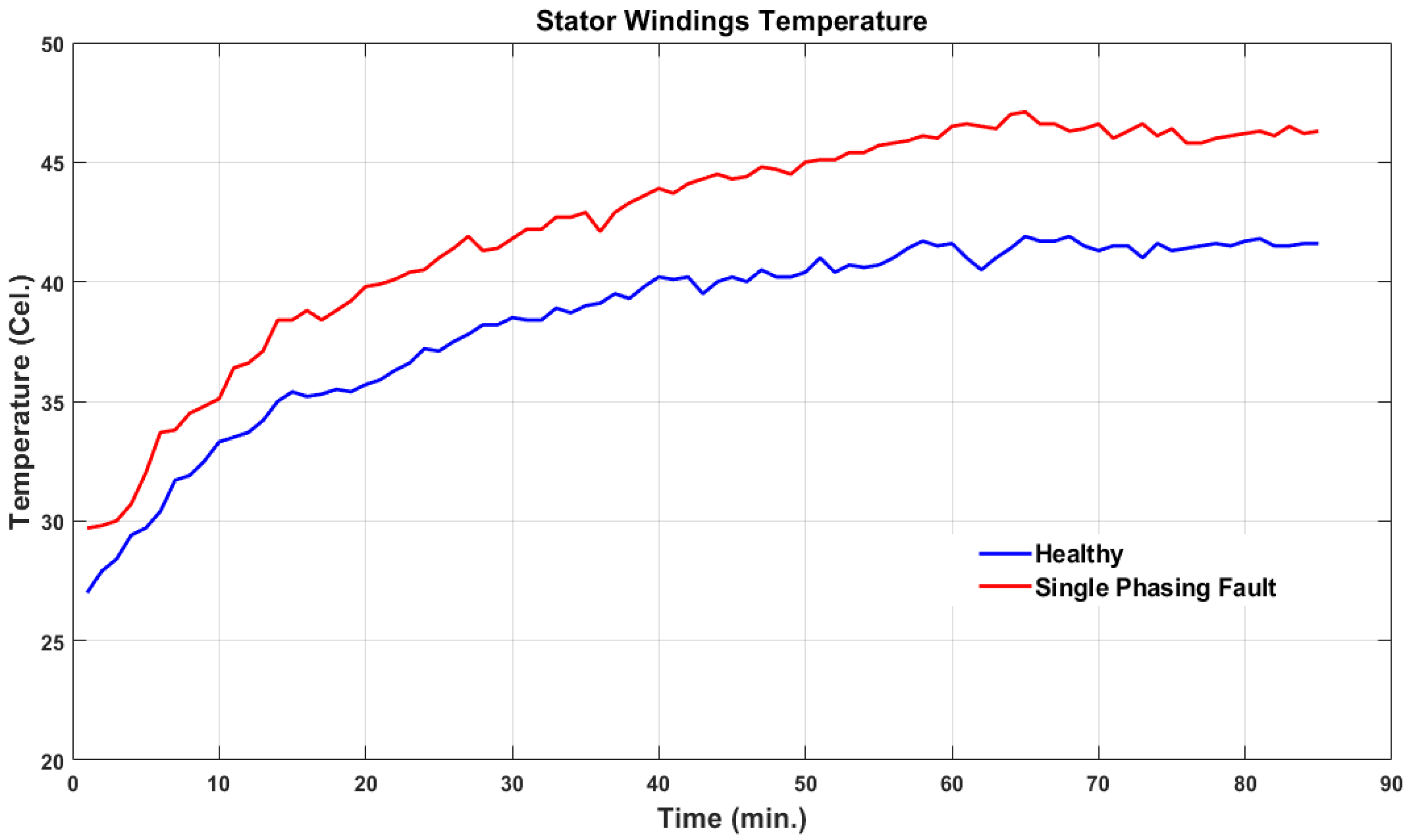
  • Measure the stator winding temperatures and motor vibration.
  • Conduct extensive experiments on a three-phase induction motor to determine the most effective protection settings.
The main contribution of this paper is to investigate the operation of a three-phase induction motor under a single-phasing fault and make new or innovative recommendations for the operation of a three-phase induction motor under this fault.
The paper is organized as follows: after the introduction in Section 1, Section 2 presents the theoretical analysis of single-phasing faults, and proposes the basic idea of this research. Section 3 contains practice tests and theoretical calculations of the three-phase induction motor under various load conditions as well as the simulation results. Section 4 presents the proposed motor protection scheme. Section 5 discusses the obtained results and gives recommendations for motor operation. Section 6 contains the conclusion.

2. Preliminaries and Basic Idea

The analysis of single-phasing faults is essential to this research; therefore, the basic theoretical equations are given in the following subsection.

2.1. Circuit Analysis Single—Phasing Fault

When one of the three phases is opened, as shown in Figure 1, single phasing occurs. In electrical analysis, sequence components are typically used to analyze unbalanced conditions [2]. The terminal voltages are resolved into positive, negative, and zero sequence components. As a result, the phase voltages at the three-phase induction motor’s terminals are given in matrix form, as shown in Equation (1).
V a n V b n V c n = 1 1 1 1 a 2 a 1 a a 2 V a 0 V a 1 V a 2   ;   a = 1 120 ° a 2 = 1 240 °
where V an ,   V bn ,   V cn are line to neutral voltages, and Va 0 , Va 1 , Va 2 are the phase voltage (zero, positive, negative) sequences, respectively. Rewriting Equation (1) using the symmetrical sequence components as follows,
V a 0 V a 1 V a 2 = 1 3 1 1 1 1 a a 2 1 a 2 a V a n V b n V c n ;   a = 1 120 ° a 2 = 1 240 °
For a single-phasing fault in Line-a, the line currents must satisfy the following:
I a = 0 ,   and   I c = I b
Therefore, the matrix form of the symmetrical sequence components of the phase-a currents becomes the following:
I a 0 I a 1 I a 2 = 1 3 1 1 1 1 a a 2 1 a 2 a 0     I b I b = 1 3 0 a a 2 I b a 2 a I b = 0 j 1 3 I b j 1 3 I b   ; a = 1 120 ° a 2 = 1 240 °
where I a ,   I b ,   I c are the three-phase currents and Ia 0 , Ia 1 , Ia 2 are the phase current (zero, positive, negative) sequences, respectively. Equation (4) shows that the zero-sequence current will not flow through a faulty phase, and I a 1 = I a 2 . As a result of the analysis in Figure 2, the input voltages of the positive and negative sequences under single-phasing conditions (5) and (6) can be calculated.
In Figure 2, the sequence input voltages are given by the following:
V i n = V a 1 V a 2        
V a 1 = 1 3 ( V a n + a V b n + a 2 V c n )
    V a 2 = 1 3 ( V a n + a 2 V b n + a V c n )    
    V i n = 1 3 ( V a n V a n + a a 2 V b n + a 2 a V c n )        
V i n = j V b c 3
where Vin is the input voltage. Equation (6) depicts a direct relationship between the induction motor’s input voltage and the actual line-to-line voltage of the electric grid.
Based on Figure 2, the sequence currents Ia1 and Ia2 can be found as follows [2]:
Z eq , i = Rs + jXs + Rr / s + jXr jXm +   Rr / s + jXr
where i = 1, 2 for positive and negative sequences, respectively.
The stator sequence currents are as follows:
I s , 1 = V i n Z e q , 1   + Z e q , 2     ,         I s , 2   = I s , 1   ,             I s , 0 = 0  
And the rotor sequence currents are as follows:
  I r , i = I s , 1 ×   j X m j   X m + Rr / s + jXr  

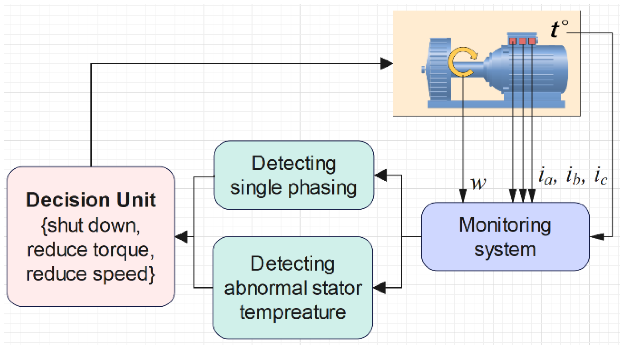
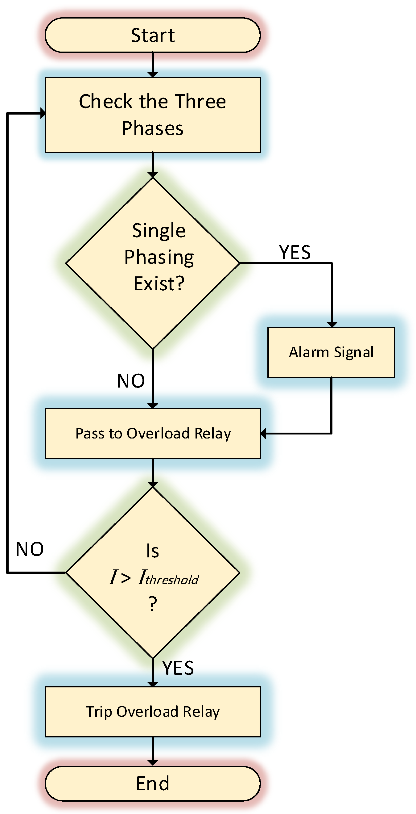
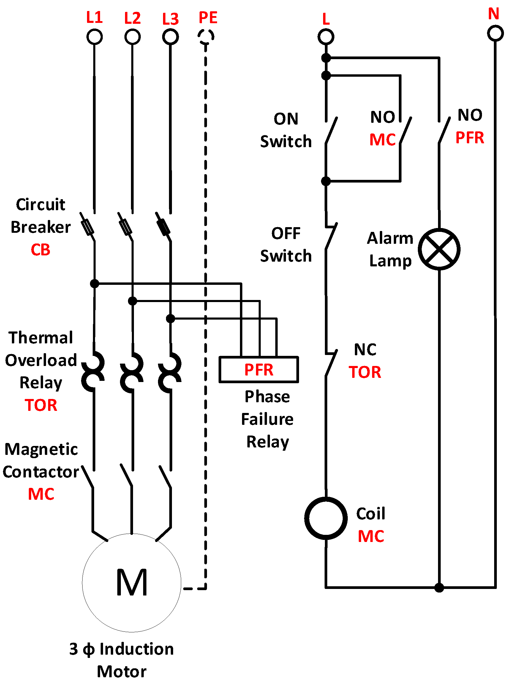
2.2. Proposed Scheme
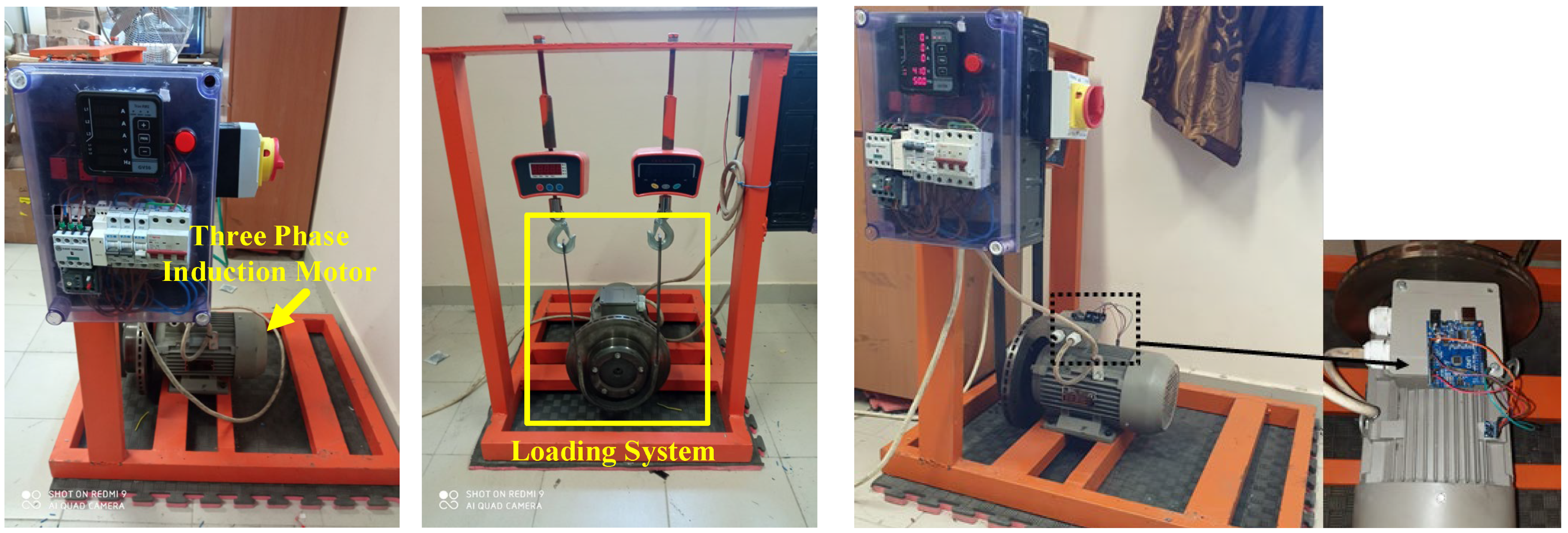
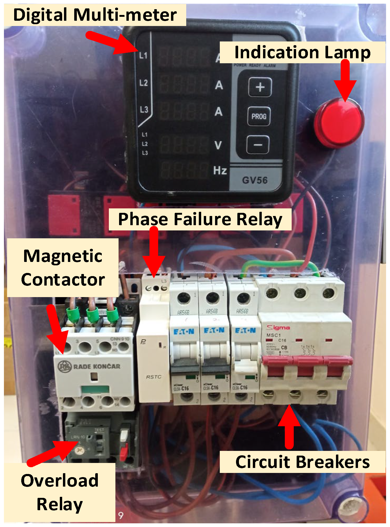
The main idea of this research is to follow the motor’s status through its operation and try to keep it working unless there is a real threat to the motor. Figure 3 shows the basic idea of this study for monitoring the three-phase induction motor by measuring its currents, stator winding temperature, vibration, and speed. Based on these measurements, a single-phasing fault can be detected as a faulty operation. In parallel with detecting single phasing, the proposed monitoring scheme can also detect any abnormal increase in winding temperature. The previous measurements are considered vital signs of the motor, and based on them, a decision unit or drive circuit decides the best action for the motor without harming it, as well as its continuity of operation, such as reducing its speed or reducing the load applied to the motor (if it is possible), or shutting down the motor if its continuity of operation will affect its lifetime or if it will probably damage it. The proposed monitoring scheme provides a reliable and efficient method for maintaining the optimal operation of motors in various industrial applications.

3. Practical Test

A practical test is performed on the motor to determine the equivalent parameters in order to simulate the three-phase operation under the single-phasing fault. Table 1 shows the rated values of the motor under consideration. The motor’s ambient temperature is 40 °C. NEMA specifies 130 °C for the insulation material of a class B induction motor. Figure 4 shows the practical test equipment, which includes a three-phase squirrel cage induction motor with braking load, a power supply, ammeters, voltmeters, and a Compact Fluke PTi120 Pocket Thermal Camera. The loading mechanism in the test benchmark is designed to be based on the friction between a vehicle drum and a vehicle brake. The accelerometer sensor (MPU6050 Module with Arduino, Electronic Cats, Aguascalientes, Mexico) is used to register the vibration on the motor.
To determine the induction motor parameters, the following tests were performed [24,25,26,27]; the results are summarized in Table 2.

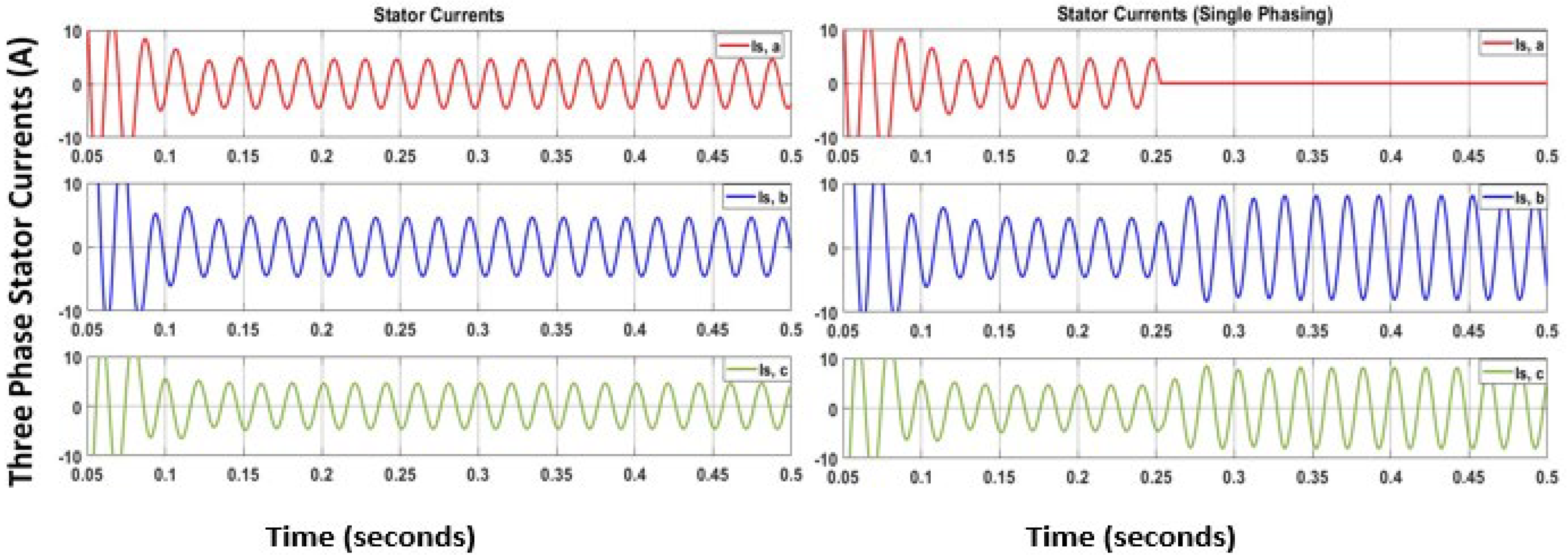
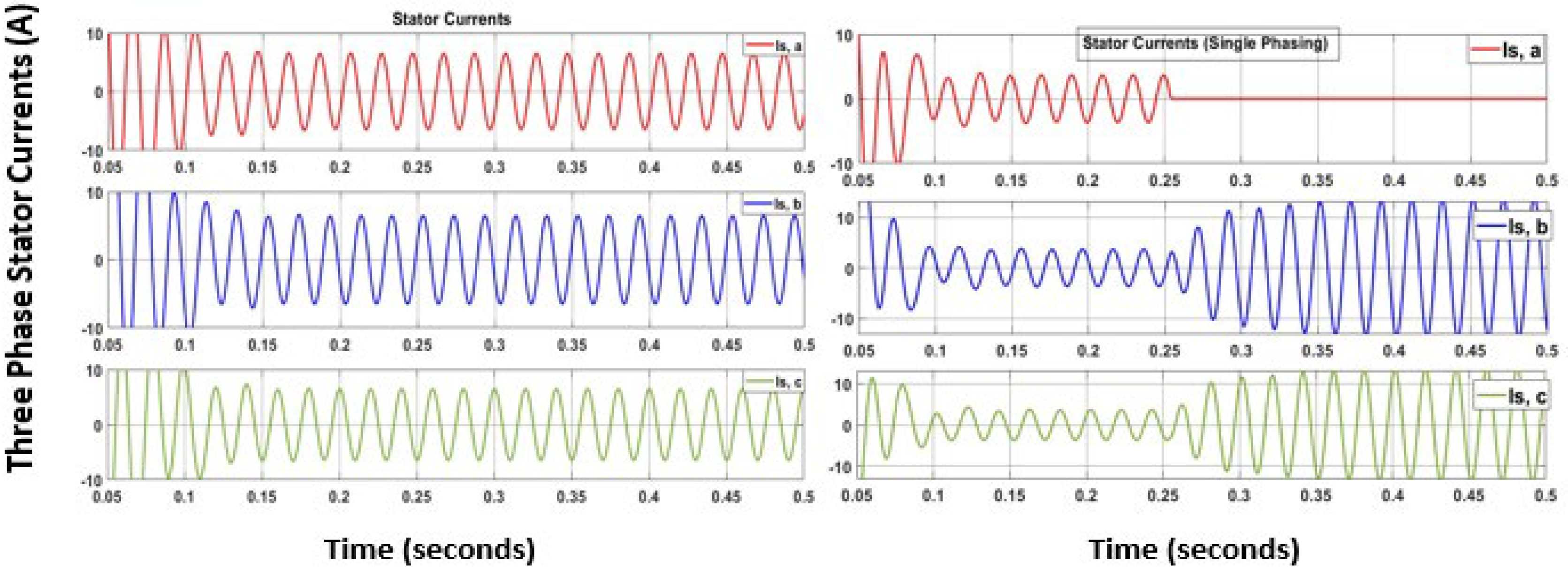
Theoretical Calculation and Simulation Results

In this subsection, the motor current calculation under normal operation conditions for a Y-connected induction motor has the following parameters per phase referred to the stator, which were found by the tests. The following basic equations are used:
η s y n = 120 P · f e
s = η s y n η m η s y n
where η s y n , η m , and s are the synchronous motor speed, motor speed, and the slip, respectively. The rotor current is calculated by the following:
I r = V ϕ R 1 + R 2 s + j ( X 1 + X 2 )
where V ϕ ,   R 1 , R 2 , X 1 , and X 2 are the phase voltage, stator resistance, rotor reflected resistance, stator reactance, and rotor reflected reactance, respectively.
The stator current is given by the following:
I s = I r + I m
I m = V ϕ / j X m            
where Im and Xm are the motor excitation current and motor excitation reactance, respectively.
To answer whether it is possible to avoid turning off the induction motor during a single-phasing fault, Matlab/Simulink (https://www.mathworks.com/products/simulink.html accessed on 20 May 2024) was used to simulate the motor model under healthy and faulty conditions. The motor model that has been implemented in Simulink is a general model [28] to compromise between simplicity and accuracy of the results since the scope of this research is practical implementation and applications. The following loading scenarios were considered: light load, half load, and full load, which indicate the load percentage of the rated current. Table 3 displays the motor speed and current values in the healthy case and single phasing (faulty) on phase-a for various torque values. These measurements were taken from the real set of the three-phase induction motor shown in Figure 4.
Table 4 shows closed results of the practical, theoretical, and simulation experiments using Matlab/Simulink for motor currents. In practice, we discovered that the motor speed decreased in a single phasing with the same load values.
Figure 5, Figure 6 and Figure 7 show the Matlab simulation results of the stator currents at healthy and single-phase fault conditions under light loading (30% of the rated value), half load, and full load, respectively.
The practical tests show a noticeable change in motor vibration and sound. The recorded result of motor vibration is shown in Figure 8 when it operated under healthy operation [0–4] seconds, and under single-phasing fault [4–10] seconds. Therefore, a fault detection hypothesis can be applied to detect the occurrence of a fault if the vibration signal exceeds the threshold value. A simple form of threshold can be calculated based on the peak value of the vibration signal under fault-free operation, i.e.,
J t h , p e a k   = s u p f a u l t f r e e   v t    
Based on the threshold value, the following hypothesis can be used to detect the faults.
v t >   J t h , p e a k             = = > a l a r m ,   f a u l t   i s   d e t e c t e d
v t         J t h , p e a k             = = > n o   a l a r m ,   f a u l t f r e e    
where, v(t) is the vibration measurement signal, and Jth, peak is the peak threshold value which is equal to 0.032.

4. Operation Un44. Single Phasing—Protection Scheme

The proposed protection scheme is quite simple and practical and aims to protect the motor from high current and its bad effect on the stator windings. In this scheme, the threshold current is specified through various practical tests in the lab to determine this value, keeping in mind the continuity of motor operation without harming it. The threshold current is also adjusted periodically to account for any changes in the motor’s operating conditions.
The results of Table 3 show that a single-phasing fault will cause an increase in motor stator current. The protection scheme is designed based on the flowchart shown in Figure 9. The components of this protection are collected from commercial products like circuit breakers (CB), thermal overload relay (TOR), magnetic contactors (MC), phase failure relays (PFR), digital multifunctional meters, and the indication lamp. Figure 10 depicts the proposed protection scheme against single phasing, and Figure 11 shows the practical implementation of the protection system.
In the normal case, there is no failure in the phases, and if the current is within the limited value, the motor will continue in its operation. In the case of single phasing, the indication lamp will be activated, and the motor will continue in its operation unless the stator current exceeds the threshold value. If the motor current exceeds the threshold current, the overload relay trips and stops the motor operation.

5. Discussion

Figure 5, Figure 6 and Figure 7 and Table 3 and Table 4 show an increase in current magnitude under single-phasing with decreasing motor speed. Figure 12, Figure 13 and Figure 14 show the simulation results of the motor speed change under healthy (0–1 s) and single phasing (starting at t = 1 s) for light, half, and full load. The simulation results demonstrate the impact of single phasing on motor performance under different load conditions. These results of speed variation are very close to the practical measurement in Table 3. The close correlation between the simulated speed variation and practical measurements validates the model’s accuracy. In addition to speed, the variation in electromagnetic torque highlights the potential for increased vibration during single-phasing events, emphasizing the importance of monitoring and addressing these issues in motor operations.
Figure 8 shows an increase in motor vibration with increasing load. Figure 15 and Figure 16 show the increase in stator winding temperature under single-phasing faults. The experimental results show that during single phasing, the current in the open phase is zero while it rises in the other phases, as shown in Table 3. Figure 15 shows the normal rise of stator winding temperature under healthy and faulty conditions at light load, and it shows that the average temperature rise is approximately constant.
To explore the distribution of heat in the motor, an infrared special camera (Compact Fluke PTi120 Pocket Thermal Camera) is used. Figure 16 shows the infrared thermal image of the stator windings, where there is a significant increase in temperature under faulty conditions compared with the healthy one in the light load case. The temperature difference in the stator windings is from (40 °C) at light load in healthy conditions to (49 °C) at fault conditions. This increase in temperature indicates a potential issue with the stator windings that may need to be addressed to prevent further damage or failure. Monitoring and analyzing these temperature differences can help in early detection of faults and maintenance planning for the motor.
To answer the paper’s question, “Should a three-phase induction motor be turned off during a single-phasing fault?”, the practical measurement considered for motor operation for long time operation under the single-phasing fault (around 85 min) under the light load revealed that the currents did not exceed the operation limits and a temperature increase of only 9 °C. This test is repeated several times, and the data are measured for long operation periods with the same behavior as shown in Figure 15.
It should be noted here that the rise in the stator current under the single-phasing fault is around 4.3 A, as seen in Table 3. If the value of the stator current exceeds the threshold value, the motor will trip and shut down. In contrast, if the value of the stator current does not exceed the threshold value, the motor will continue to operate under the light load.
The rise in the current under the light load under faulty conditions is still within permissible values; therefore, the proposed protection system will allow the motor to continue its operation. However, in half load and full load conditions, the increase in stator winding temperatures and currents will be significant enough to exceed the threshold value and activate the protection system, as shown in the preceding section. This ensures that the motor is safeguarded against overheating and damage.

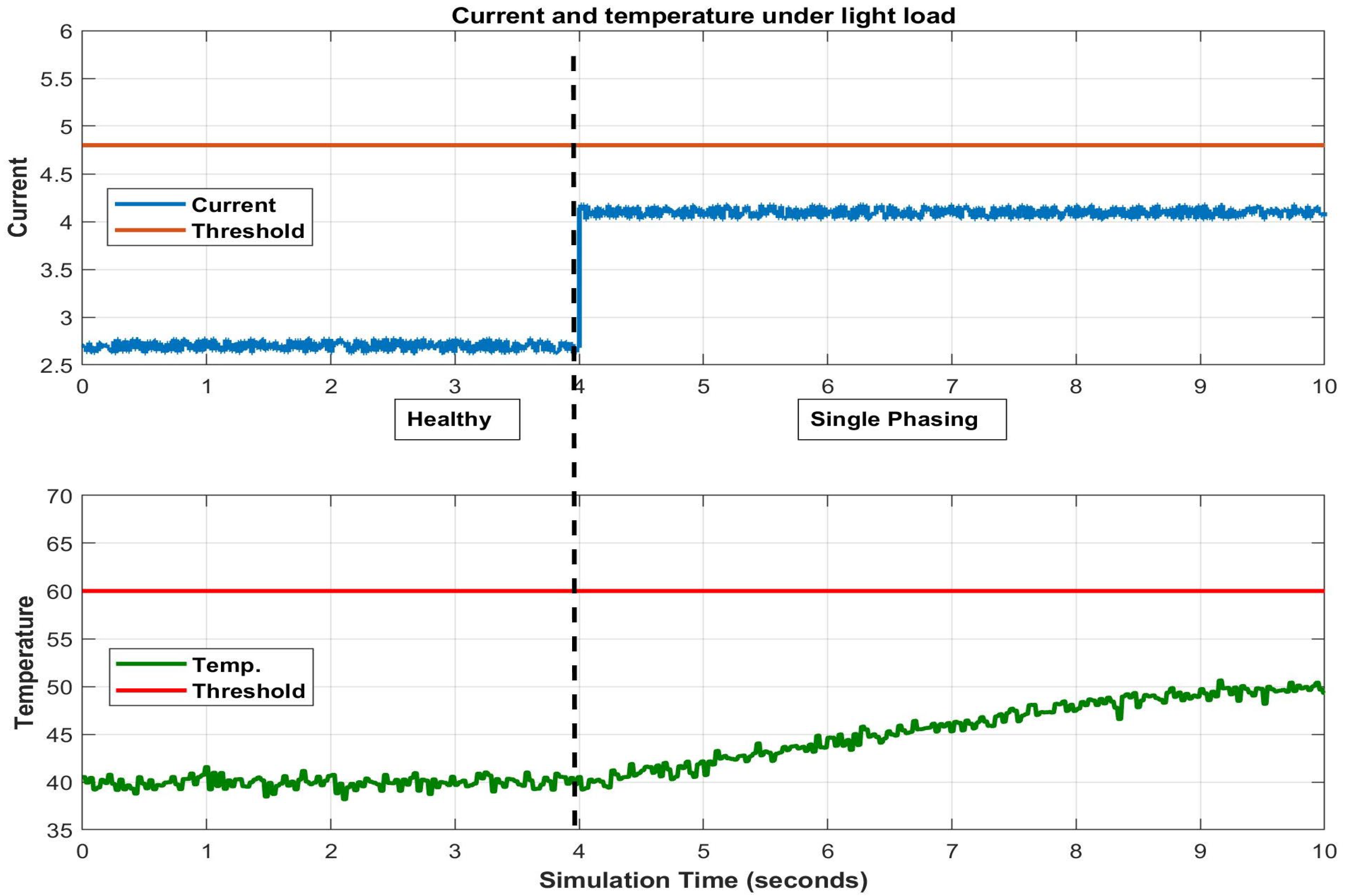
Motor Operation with Fault Detection

The proposed fault-tolerant operation of the induction motor under the single-phasing fault is to monitor the vital signs (temperature and current) of induction motors and to control the operation of the motor based on the online reading of these signals.
The simulation results in Figure 17 and Figure 18 illustrate the main idea of the proposed idea of this research. Figure 17 shows that even if a single-phasing fault occurs at Section 4, the motor will continue operating because the current and the temperature do not exceed their limit values. However, Figure 18 shows that under the half load condition, the motor exceeds the threshold value and therefore should be shut down.
By continuously monitoring the temperature and current of the motor, any abnormalities can be detected quickly, and the operation can be adjusted accordingly to prevent further damage. This proactive approach allows the motor to continue running smoothly even in the event of a single-phasing fault, ensuring that production processes are not disrupted. Additionally, the real-time monitoring of these vital signs can provide valuable data for predictive maintenance, helping to extend the lifespan of the motor and minimize downtime.

6. Conclusions

The induction motor’s single-phasing fault is presented and illustrated theoretically and practically through practical tests, theoretical calculations, and simulation. Single phasing reduced the motor speed while increasing the currents in the other phases under certain loading conditions. To ensure that the motor currents in the experimental settings do not exceed the permissible limits, a protection scheme was introduced and implemented.
It is important to note the following:
  • The proposed protection scheme is practical, and a fault-tolerant control scheme can be used to make the three-phase induction motor run more reliably and safely under the single-phasing fault.
  • It has been discovered that the stator winding temperature should be considered in any advanced research on motor operation during single phasing.
The preliminary findings of this study (based on extensive experimental and practical tests) indicate that the three-phase induction motor could continue to operate safely at 30% of full load under a single-phasing fault, which can be advantageous in induction motor applications such as cooling systems, ventilation, and maybe some elevator applications. Overall, these findings have the potential to significantly impact industries that rely on three-phase induction motors for critical operations. This level of resilience to single-phasing faults could save companies time and money by avoiding unexpected downtime and maintenance costs.
The vibration signal shown in Figure 8 and the temperature signal shown in Figure 12 are collected in healthy and faulty conditions. These data could be used for further research on fault detection based on artificial intelligence (AI). We plan to develop a machine learning algorithm that accurately detects faults based on these signals.

Author Contributions

Conceptualization, A.A. (Ali Abdo); Methodology, A.A. (Ali Abdo) and R.M.; Software, J.S.; Validation, H.S.; Formal analysis, J.S. and A.A. (Ahmed Abdou); Investigation, J.S., A.A. (Ahmed Abdou) and R.M.; Data curation, H.S.; Writing—original draft, A.A. (Ali Abdo); Writing—review & editing, A.A. (Ahmed Abdou), H.S. and R.M. All authors have read and agreed to the published version of the manuscript.

Funding

This work was supported in part by the Research Committee, Birzeit University.

Data Availability Statement

Data is contained within the article.

Conflicts of Interest

The authors declare no conflicts of interest.

Nomenclature

V a n , V b n , V c n Line to neutral voltages I r Motor rotor current
I a , I b , I c Three phase current I m Motor excitation current
I a 0 , I a 1 , I a 2 Sequence currents (zero, positive, negative, respectively) η s y n Synchronous motor speed (rpm)
V a 0 , V a 1 , V a 2 Sequence voltages (zero, positive, negative, respectively) J t h , p e a k   Peak threshold value
R 1 Motor stator resistance η m Motor speed (rpm)
R 2 Motor-reflected rotor resistance V ϕ Motor Phase Voltage
X 1 Motor stator reactance f e Electrical frequency (50 Hz)
X 2 Motor-reflected rotor reactance P Motor number of poles
X m Motor excitation reactanceHHealthy condition
I s Motor stator currentFFaulty condition (single phasing)
v t Vibration measured signal

References

  1. Chen, W.-K. Fortune Business Insight, Induction Motor Market Size, Share & Industry Analysis, by Type (Single Phase, Three Phase) by Application (Residential, Industrial, Commercial, Transportation, Others) and Regional Forecast; Report Id: Fbi101639, 2021; Linear Networks and Systems (Book Style); Wadsworth: Belmont, CA, USA, 1993; pp. 123–135. [Google Scholar]
  2. Kersting, W. Causes and Effects of Single-Phasing Induction Motors. IEEE Trans. Ind. Appl. 2005, 41, 1499–1505. [Google Scholar] [CrossRef]
  3. Guasch-Pesquer, L.; Youb, L.; González-Molina, F.; Zeppa-Durigutti, E.-R. Effects of Voltage Unbalance on Torque and Current of the Induction Motors. In Proceedings of the 2012 13th International Conference on Optimization of Electrical and Electronic Equipment (OP-TIM), Brasov, Romania, 24–26 May 2012; pp. 647–652. [Google Scholar] [CrossRef]
  4. Dash, R.N.; Sahu, S.; Panigrahi, C.K. Effect and Analysis of Unbalanced Voltage on Induction Motor Torque. In Proceedings of the 2018 International Conference on Recent Innovations in Electrical, Electronics & Communication Engineering (ICRIEECE), Bhubaneswar, India, 27–28 July 2018; pp. 2698–2703. [Google Scholar] [CrossRef]
  5. Siddique, J.A.; Yadava, G.S.; Singh, B. Effects of Voltage Unbalance on Induction Motors. In Proceedings of the Conference Record of the 2004 IEEE International Symposium on Electrical Insulation, Indianapolis, IN, USA, 19–22 September 2004; pp. 26–29. [Google Scholar] [CrossRef]
  6. Dekhandji, F.Z.; Refoufi, L.; Bentarzi, H. Quantitative Assessment of Three Phase Supply Voltage Unbalance Effects on Induction Motors. Int. J. Syst. Assur. Eng. Manag. 2015, 8, 393–406. [Google Scholar] [CrossRef]
  7. Sudasinghe, P.; Perera, S.; Commins, P.; Moscrop, J.; Jayatunga, U.; Wadduwage, P. Rediscovering the Derating Mechanisms for Three-Phase Induction Motors Operating Under Supply Voltage Unbalance. In Proceedings of the 2020 19th International Conference on Harmonics and Quality of Power (ICHQP), Dubai, United Arab Emirates, 6–7 July 2020; pp. 1–6. [Google Scholar] [CrossRef]
  8. Quispe, E.C.; López-Fernández, X.M.; Mendes, A.M.S.; Marques Cardoso, A.J.; Palacios, J.A. Experimental Study of the Effect of Positive Sequence Voltage on the Derating of Induction Motors Under Voltage Unbalance. In Proceedings of the 2011 IEEE Inter-national Electric Machines & Drives Conference (IEMDC), Niagara Falls, ON, Canada, 15–18 May 2011; pp. 908–912. [Google Scholar] [CrossRef]
  9. Ogbuka, C.U.; Bassey, O. Protection Method Against Induction Motor Single-Phasing Fault. Int. J. Innov. Technol. Explor. Eng. (IJITEE) 2014, 4, 61–65. [Google Scholar]
  10. Giceva, I.Z.; Sarac, V.J.; Gelev, S.A.; Cingoski, V.T. Single Phasing of Three Phase Induction Motors Under Various Load Conditions. In Proceedings of the 2018 23rd International Scientific-Professional Conference on Information Technology (It), Zabljak, Montenegro, 19–24 February 2018; pp. 1–4. [Google Scholar] [CrossRef]
  11. Duarte, S.X.; Kagan, N. A Power-Quality Index to Assess the Impact of Voltage Harmonic Distortions and Unbalanced to Three-Phase Induction Motors. IEEE Trans. Power Deliv. 2010, 25, 1846–1854. [Google Scholar] [CrossRef]
  12. Gonzalez-Cordoba, J.L.; Osornio-Rios, R.A.; Granados-Lieberman, D.; Romero-Troncoso, R.D.J.; Valtierra-Rodriguez, M. Thermal-Impact-Based Protection of Induction Motors Under Voltage Unbalance Conditions. IEEE Trans. Energy Convers. 2018, 33, 1748–1756. [Google Scholar] [CrossRef]
  13. Sudha, M.; Anbalagan, P. A Novel Protecting Method for Induction Motor Against Faults Due to Voltage Unbalance and Single Phasing. In Proceedings of the IECON 2007—33rd Annual Conference of the IEEE Industrial Electronics Society, Taipei, Taiwan, 5–8 November 2007; pp. 1144–1148. [Google Scholar] [CrossRef]
  14. Sobanski, P.; Orlowska-Kowalska, T. Faults Diagnosis and Control in a Low-Cost Fault-Tolerant Induction Motor Drive System. Math. Comput. Simul. 2017, 131, 217–233. [Google Scholar] [CrossRef]
  15. Abbasi, H.; Ghanbari, M.; Ebrahimi, R.; Jannati, M. Post-Fault Operation Strategy for Single Open-Phase Fault in Three-Phase Induction Motor Drives. IET Power Electron. 2022, 15, 1174–1188. [Google Scholar] [CrossRef]
  16. Abbasi, H.; Ghanbari, M.; Ebrahimi, R.; Jannati, M. IRFOC of Induction Motor Drives Under Open-Phase Fault Using Balanced and Unbalanced Transformation Matrices. IEEE Trans. Ind. Electron. 2020, 68, 9160–9173. [Google Scholar] [CrossRef]
  17. Jannati, M.; Idris, N.R.N.; Aziz, M.J.A. Performance Evaluation of the Field-Oriented Control of Star-Connected 3-Phase Induction Motor Drives Under Stator Winding Open-Circuit Faults. J. Power Electron. 2016, 16, 982–993. [Google Scholar] [CrossRef]
  18. Jannati, M.; Monadi, A.; Idris, N.R.N.; Abdul Aziz, M.J. Experimental Evaluation of FOC of 3-Phase IM Under Open-Phase Fault. Int. J. Electron. 2017, 104, 1675–1688. [Google Scholar] [CrossRef]
  19. Forstner, G.; Kugi, A.; Kemmetmüller, W. Fault-Tolerant Torque Control of a Three-Phase Permanent Magnet Synchronous Motor with Inter-Turn Winding Short Circuit. Control. Eng. Pr. 2021, 113, 104846. [Google Scholar] [CrossRef]
  20. Costa, B.L.G.; Graciola, C.L.; Angélico, B.A.; Goedtel, A.; Castoldi, M.F.; Andrade Pereira, W.C. A Practical Framework for Tuning Dtc-Svm Drive of Three-Phase Induction Motors. Control. Eng. Pr. 2019, 88, 119–127. [Google Scholar] [CrossRef]
  21. Saffar, E.; Ghanbari, M.; Ebrahimi, R.; Jannati, M. A Simple Fault-Tolerant Control Method for Open-Phase Three-Phase Induction Motor Drives. Control. Eng. Pract. 2023, 136, 105525. [Google Scholar] [CrossRef]
  22. Nikpayam, M.; Ghanbari, M.; Esmaeli, A.; Jannati, M. Fault-tolerant control of Y-connected three-phase induction motor drives without speed measurement. Measurement 2020, 149, 106993. [Google Scholar] [CrossRef]
  23. Saffar, E.; Ghanbari, M.; Ebrahimi, R. Single open-phase fault detection and tolerant control for wye-connected three-phase induction machine drives. Int. J. Circuit Theory Appl. 2024. [Google Scholar] [CrossRef]
  24. Klempner, G.; Kerszenbaum, I. Principles of Operation of Synchronous Machines. In Handbook of Large Turbo-Generator Operation and Maintenance; IEEE: Piscataway, NJ, USA, 2018; pp. 1–52. [Google Scholar] [CrossRef]
  25. Anderson, P.M.; Henville, C.; Rifaat, R.; Johnson, B.; Meliopoulos, S. Motor Protection. In Power System Protection; IEEE: Piscataway, NJ, USA, 2022; pp. 805–860. [Google Scholar] [CrossRef]
  26. Joe, H.C.; Juan, J. Sanchez-Gasca Load and Induction Motor Models. In Power System Modeling, Computation, and Control; IEEE: Piscataway, NJ, USA, 2020; pp. 295–325. [Google Scholar] [CrossRef]
  27. Rahmatullah, R.; OYMAN SERTELLER, N.F.; TOPUZ, V. Modeling and Simulation of Faulty Induction Motor in DQ Reference Frame Using MATLAB/SIMULINK with MATLAB/GUIDE for Educational Purpose. Int. J. Educ. Inf. Technol. 2023, 17, 7–20. [Google Scholar] [CrossRef]
  28. Chapman, S.J. Electric Machinery Fundamentals, 5th ed.; Mcgraw-Hill: New York, NY, USA, 2012. [Google Scholar]
Figure 1. Single phasing in three-phase induction motor.
Applsci 14 04690 g001
Figure 2. Positive and negative sequence network for single phasing.
Applsci 14 04690 g002
Figure 3. Proposed method of monitoring three-phase induction motor.
Applsci 14 04690 g003
Figure 4. Benchmark test in the lab.
Applsci 14 04690 g004
Figure 5. Healthy and faulty stator currents at light load.
Applsci 14 04690 g005
Figure 6. Healthy and faulty stator currents at half load.
Applsci 14 04690 g006
Figure 7. Healthy and faulty stator currents at full load.
Applsci 14 04690 g007
Figure 8. Motor vibration under healthy and faulty cases with a threshold value.
Applsci 14 04690 g008
Figure 9. The flowchart of the protection scheme.
Applsci 14 04690 g009
Figure 10. Proposed protection scheme against single-phasing fault.
Applsci 14 04690 g010
Figure 11. Experimental work for the prototype design.
Applsci 14 04690 g011
Figure 12. Speed and electromagnetic torque under healthy (0 to 1 s) and single phasing (1 to 2 s) operations under the light load.
Applsci 14 04690 g012
Figure 13. Speed and electromagnetic torque under healthy (0 to 1 s) and single phasing (1 to 2 s) operations under the half load.
Applsci 14 04690 g013
Figure 14. Speed and electromagnetic torque under healthy (0 to 1 s) and single phasing (1 to 2 s) operations under the full load.
Applsci 14 04690 g014
Figure 15. Stator windings temperature under light load (healthy and faulty conditions).
Applsci 14 04690 g015
Figure 16. Infrared thermal image of the stator windings under light load (healthy and faulty conditions).
Applsci 14 04690 g016
Figure 17. Current and temperature under healthy and single-phasing fault for the light load.
Applsci 14 04690 g017
Figure 18. Current and temperature under healthy and single-phasing fault for the half load.
Applsci 14 04690 g018
Table 1. Motor nameplate values.
MotorThree-Phase Squirrel Cage Induction Motor
Power Factor0.81
Power2.2 kW
Frequency50 Hz
Rated Voltage Δ/Y230/400 V
Rated Current Δ/Y8.4/4.8 A
Weight19.8 kg
Rated Speed1420 rpm
Ambient Temp. 40 °C
ClassB
Table 2. Motor tests and parameters.
TestParameters
DC test R 1 Y = V D C 2 I D C = 31.6 2 4.6 = 3.44    
No-load test V L / 3 I L X 1 + X m 414 / 3 2.7                         =   88.53   Ω
Blocked rotor test R 1 = 3.44   Ω     R 2 = 4.13   Ω
X 1 = 2.36   Ω       X 2 = 2.36   Ω       X m = 86.17   Ω
The abbreviations of the parameters are given in the nomenclature at the end of the paper.
Table 3. Healthy and faulty (single phasing) results under different load conditions.
TestLight LoadHalf LoadFull Load
HFHFHF
Speed [rpm]149714971440140514101330
Ia [A]2.703.704.40
Ib [A]2.74.13.774.49.2
Ic [A]2.74.13.774.49.2
H: healthy; F: faulty.
Table 4. Validation of the output results under different load conditions.
Testmotor current under
healthy case [a]
motor current under
single phasing [a]
Light load torquePractical2.74.1
Theoretical2.684.25
Simulation2.64.27
Half load torquePractical3.77.0
Theoretical3.56.4
Simulation3.246.4
Full load torquePractical4.49.2
Theoretical4.39.07
Simulation4.69.09
Disclaimer/Publisher’s Note: The statements, opinions and data contained in all publications are solely those of the individual author(s) and contributor(s) and not of MDPI and/or the editor(s). MDPI and/or the editor(s) disclaim responsibility for any injury to people or property resulting from any ideas, methods, instructions or products referred to in the content.

