Article

Region-Selective Corrosion for the Fabrication of Tilted Microfiber Bragg Gratings: A Candidate for the Monitoring of Buildings’ Health

1
School of Architecture, Chang’an University, Xi’an 710061, China
2
College of Information Science and Engineering, Northeastern University, Shenyang 110819, China
*
Author to whom correspondence should be addressed.
Appl. Sci. 2024, 14(11), 4707; https://doi.org/10.3390/app14114707
Submission received: 23 April 2024 / Revised: 28 May 2024 / Accepted: 28 May 2024 / Published: 30 May 2024
(This article belongs to the Special Issue Recent Trends in Fiber Optic Sensor: Technology and Applications)

Abstract

:
Optical fiber gratings can be appropriately packaged and integrated for the real-time monitoring of the structural health of buildings or composite-material films. In this work, a tilted fiber Bragg grating at the micron scale was proposed, designed, and optimized via simulation model analysis using OptiFDTD software. The effects of the grating inclination, grating period, and grating length on the transmission spectrum of the tilted microfiber Bragg grating (TMFBG) were studied. The transmission spectrum’s responses to different refractive indices were simulated and compared. A TFBG was uniformly etched with hydrofluoric acid based on the chemical etching method, and several TMFBGs with different diameters were prepared. The refractive index-sensing characteristics of the TMFBGs with different structures were studied. It was found that the sensitivity of the etched TFBG was greatly improved from 0.964 nm/RIU to 6.368 nm/RIU for the higher-order cladding mode, and from 0.294 nm/RIU to 2.353 nm/RIU for the lower-order cladding mode, being approximately six times and eight times higher, respectively.

1. Introduction

Microfibers have a diameter of dozens of microns or even several hundred nanometers [1], as well as some outstanding properties, such as high transmission efficiency (>90%), low noise (0.2–0.5dB), and small signal loss (<1 dB/m) [2,3,4]. By combining microfiber and fiber Bragg grating (FBG) technologies, a microfiber Bragg grating (MFBG) can be developed to detect physical qualities (such as temperature [5], stress [6], pressure [7], etc.) with high sensitivity and can be applied in structural health monitoring [8], medical diagnosis [9], biosensing [10], environmental monitoring [7], etc.
MFBGs are prepared by reducing the diameters of common FBGs to the micron- or even nanometer level using methods such as chemical corrosion and taper pulling [5,11]. Conventional FBGs are insensitive to the external environment because all of the light signals are tightly confined near the fiber core [12], so the FBGs cannot detect a refractive index outside the fiber structure. If the cladding diameter of the FBG is reduced to tens of microns or nanometers, a strong evanescent field will be launched and transmitted along the core’s surface [13,14], where the change in the refractive index in the external environment can be monitored in a timely manner. Based on this mechanism, FBGs can be used for the detection of the refractive index. MFBGs combine the evanescent field characteristics of microfibers with the wavelength selection characteristics of traditional FBGs. The evanescent field characteristics of microfibers can effectively enhance the refractive index sensitivity of FBGs [15] and offer the ability to perform wavelength selection [16].
MFBGs have higher sensitivity or accuracy regarding the refractive index and stress than ordinary FBGs [10,17,18]. Ran used a 193 nm excimer laser to fabricate MFBGs [19]. They presented the Bragg gratings in microfibers with different diameters and studied their refractive index-sensing characteristics. The smaller diameters of the MFBGs made them more sensitive to changes in the external environment [20].
Compared to other types of FBGs, a tilted FBG (TFBG) has a unique structure in which its grating plane has a certain angle with respect to the axial direction of the optical fiber [21]. Therefore, in addition to the characteristics of FBGs, TFBGs have their own unique advantages [22]. Some optical fiber sensors have been developed by reducing the cladding diameter of the TFBG. Kameyama et al. studied the influence of the fiber core and cladding diameter of TFBGs on the simultaneous measurement of the liquid refractive index and temperature [23]. In order to improve the measurement accuracy, it is necessary to balance the diameters of the fiber core and cladding. Tomyshev analyzed the influence of the cladding diameter on the sensing accuracy of a TFBG using the spectral envelope method [24]. The results showed that the sensor’s accuracy will decrease with a decrease in the fiber cladding diameter, but the extinction ratio of the spectrum will increase.
The motive of this study is to design and demonstrate a tilted microfiber Bragg grating (TMFBG) with a uniform diameter distribution along the fiber. In previous works, in order to obtain a microstructural TFBG, the material was completely immersed in hydrofluoric acid. The obtained TMFBG is a biconical structure with a long conical transition region and two tapering regions on both ends. It is difficult to accurately analyze its optical properties and sensing performance. At the same time, there is no theoretical simulation model for reference. In this study, the theoretical model of a TMFBG was constructed with OptiFDTD, and the influence of its structural parameters on the spectral characteristics was studied. Based on the capillary protection (as a sacrificial layer) method, the selective corrosion of the TFBG region was realized, and a TMFBG with a uniform outer diameter was obtained.

2. Materials and Methods

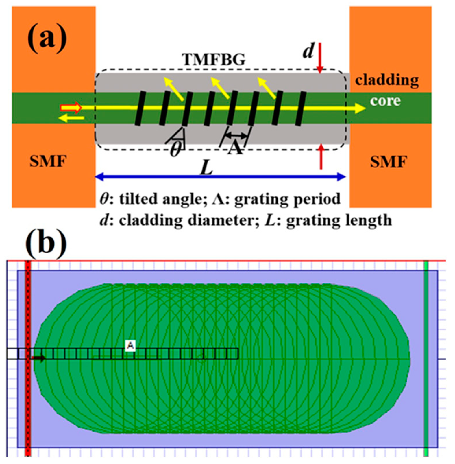
2.1. Simulation Model and TMFBG Structures

The structural parameters of the TMFBG mainly included the grating length (L), grating tilt angle (θ), grating period (Λ), cladding diameter (d), and refractive index modulation depth. The schematic is illustrated in Figure 1a. By changing the structural parameters of the TMFBG, the transmission spectrum could be changed, in addition to its regularity. The variation in the transmission spectrum mainly refers to the central wavelength, bandwidth, and transmittance.
The simulation model of the TMFBG was established utilizing OptiFDTD 8.0 software, as shown in Figure 1b. The length of the entire grating part was set to 20 μm. The main parameters of the model included the following: the refractive index of the fiber core was 1.46; the diameter of the fiber core was 8 μm; the refractive index of the cladding was 1.45; the microfiber diameter was 9 μm; the ambient refractive index was 1; and the working wavelength was centered at 1.55 μm.

2.2. Sensing Theory

Usually, a change in the external refractive index will affect the period of the fiber grating and the effective refractive index of the fiber core, which will further exert an impact on the transmission spectrum. In general, the sensitivity of the ambient refractive index can be obtained by calculating the intensity or phase change of the transmission spectrum. The cladding mode of the TFBG is directly related to the refractive index of the external environment; meanwhile, the core mode is not sensitive to changes in the ambient refractive index.
In a single-mode fiber, the angle between the grid surface and the core axial direction enhances the coupling effect between the forward-transmitted core mode and the backward-transmitted cladding mode, and it reduces the inter-coupling process with the backward-transmitted core mode.
The phase matching conditions are [25]
λ B = 2 n 0 Λ cos θ = 2 n 0 Λ g
λ i = n 0 + n i Λ cos θ
where Λ is the grid period along the fiber core direction; Λg is the grid spacing in the parallel direction; θ is the inclination angle of the gate surface; n0 is the effective refractive index of the fiber core; and ni is the effective refractive index of the i-th cladding mode.
In general, the response of the core refractive index to the external environment is extremely small, and it can be set as zero. According to the phase matching condition, it is concluded that a change in the ambient refractive index will shift the wavelength of the cladding mode. Therefore, the ambient refractive index can be detected by detecting the wavelength change of the cladding mode.

3. Results and Discussion

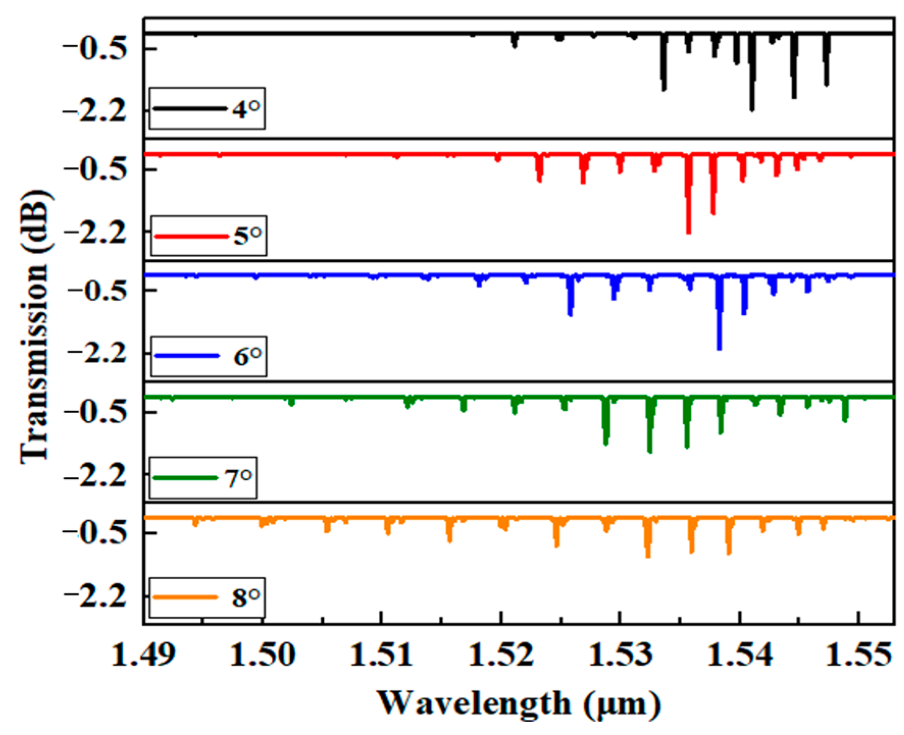
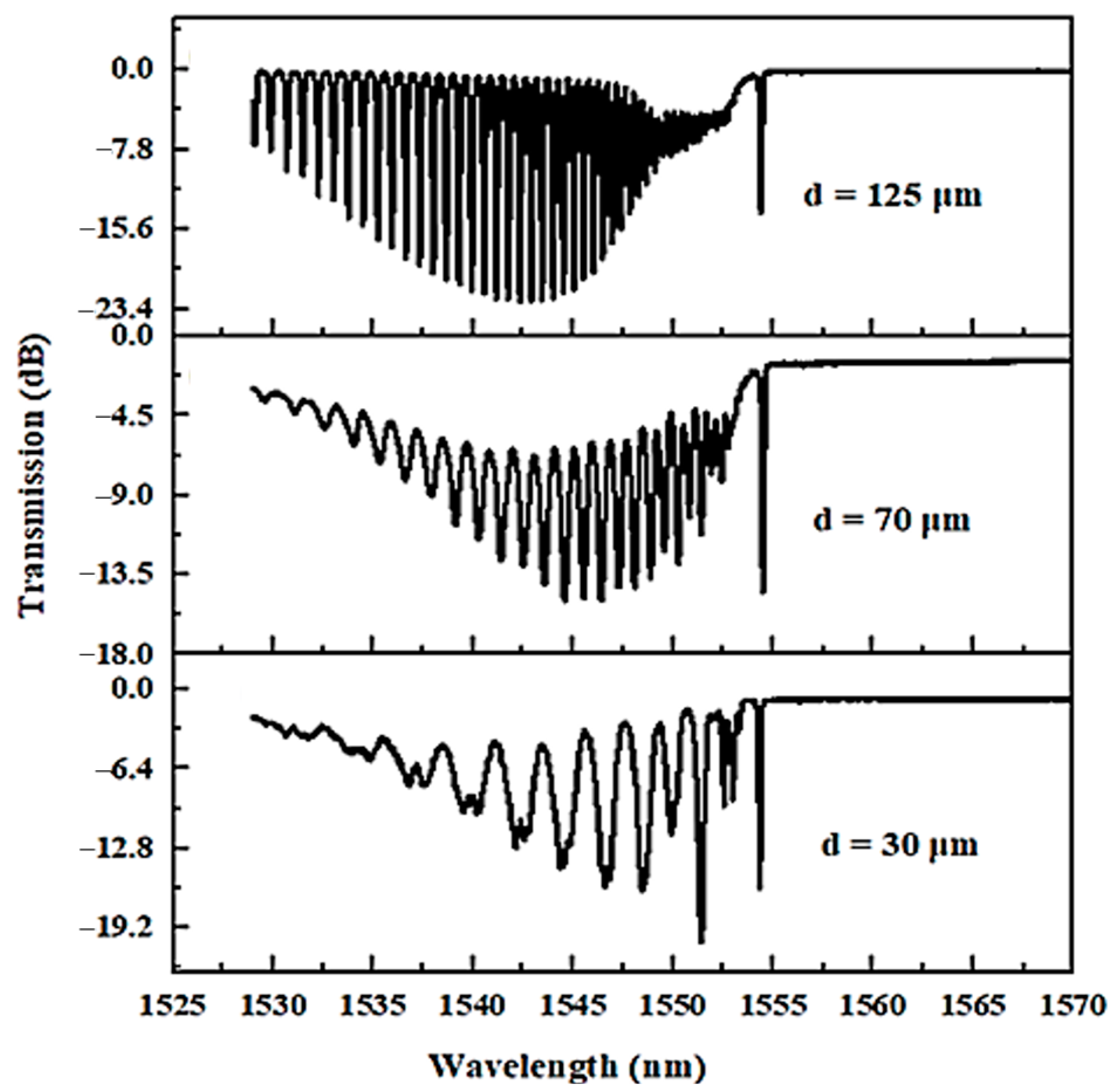
3.1. Structural Parameters and Transmission Spectrum

The structural parameters will determine the spectrum parameters of the TMFBG, namely, its intensity, bandwidth, and central wavelength. Using the OptiGrating 8.0 simulation software of the OptiWave Company (Ottawa, ON, Canada), the transmission spectrum was studied to optimize the tilt angle, grating length, grating period, and refractive index modulation depth of the TMFBG. When the inclination angles of the TMFBG were 4°, 5°, 6°, 7°, and 8°, the transmission spectra were as shown in Figure 2. In the simulation model, the external environment was a cylindrical boundary coaxial with the optical fiber, with a radius of 100 μm and a refractive index of 1.33. The grating period was 0.53 μm; the grating length was 10,000 μm; and the modulation depth was 0.0001. The grating inclination changed from 4°, 5°, 6°, and 7° to 8°.
In the transmission spectra of the TMFBG, the core mode at the right side has the longest wavelength value and transmits inside the fiber core. When the light signals escape out from the fiber core, they will transmit in the cladding layer of optical fiber in the higher-ordered modes and be named cladding modes. The number of cladding modes increases with the increasing grating inclination. Because the coupling between the core modes becomes weaker as the angle increases, the coupling between the forward transmitted core mode and the backward transmitted cladding mode is enhanced, which produces more cladding modes [26]. Comparing the results for the 4° and 8° tilt angles, in addition to the increasing number of cladding modes, there is also the disappearance of the low-order cladding modes. As the angle decreases, more energy from the forward core modes is coupled to the radiation mode. In addition to the cladding mode, the transmission depth of the core mode also decreases with the increase in the tilt angle. A greater tilt angle mainly affects the grating visibility, and it ultimately affects the transmission power. Therefore, with an increase in the grating inclination, the visibility of the grating becomes lower, and the transmission depth becomes smaller. The simulation results clearly describe the relationship between the grating inclination and the transmission spectrum of the TMFBG.
In Figure 3, the grating periods of the TMFBG are, respectively, 0.526 μm, 0.528 μm, 0.530 μm, 0.532 μm, and 0.534 μm. The corresponding transmission spectra are compared. Here, the grating inclination is fixed at 4°. As the grating period gradually increases from 0.526 μm to 0.534 μm, the wavelengths of the core mode and the cladding mode in the transmission spectrum are red-shifted as a whole.
The transmission depths of the core mode and the cladding mode scarcely change. Therefore, when keeping the other morphological parameters unchanged, the grating period has a linear dependence on the wavelength location. The change in the grating period only affects the position of the resonant peak for each order of the grating, with no effect on the transmission intensity.
When the grating length is, respectively, set to 10 mm, 20 mm, 30 mm, 40 mm, and 50 mm, the transmission spectrum of the TMFBG is shown in Figure 4. The grating inclination, the grating period, and the modulation depth are 4°, 0.53 μm, and 0.0001, respectively. With the increase in the grating length from 10 mm to 50 mm, the transmission depth of the resonant dips for the core mode and cladding modes increases continuously. It is seen that the transmission power of the core mode (at the wavelength of ~1.547 μm) increases by 18 dB (from −2 dB to −20 dB). When the grating length increases, the transmission spectrum does not shift, and the number of modes propagating in the grating is not affected. Therefore, when the resonant dip intensity is weakened with the decrease in the tilt angle, it can be appropriately compensated for by increasing the grating length.
In Figure 5, which compares the transmission spectrum changes of the TMFBG, the grating refractive index modulation depth is set to 0.0001, 0.0002, 0.0003, 0.0004, and 0.0005, respectively.
The wavelength positions of all modes are maintained. However, as the modulation depth increases from 0.0001 to 0.0005, the transmission depth gradually increases. When the modulation depth is 0.0001, the maximum transmission power is approximately −2 dB. When it increases to 0.0005, the transmission depth increases significantly, with a maximum power of approximately −30 dB. Therefore, it is concluded that an increase in the refractive index modulation depth will also change the transmission depth of the core mode and the cladding mode, but it will not change their wavelength positions.

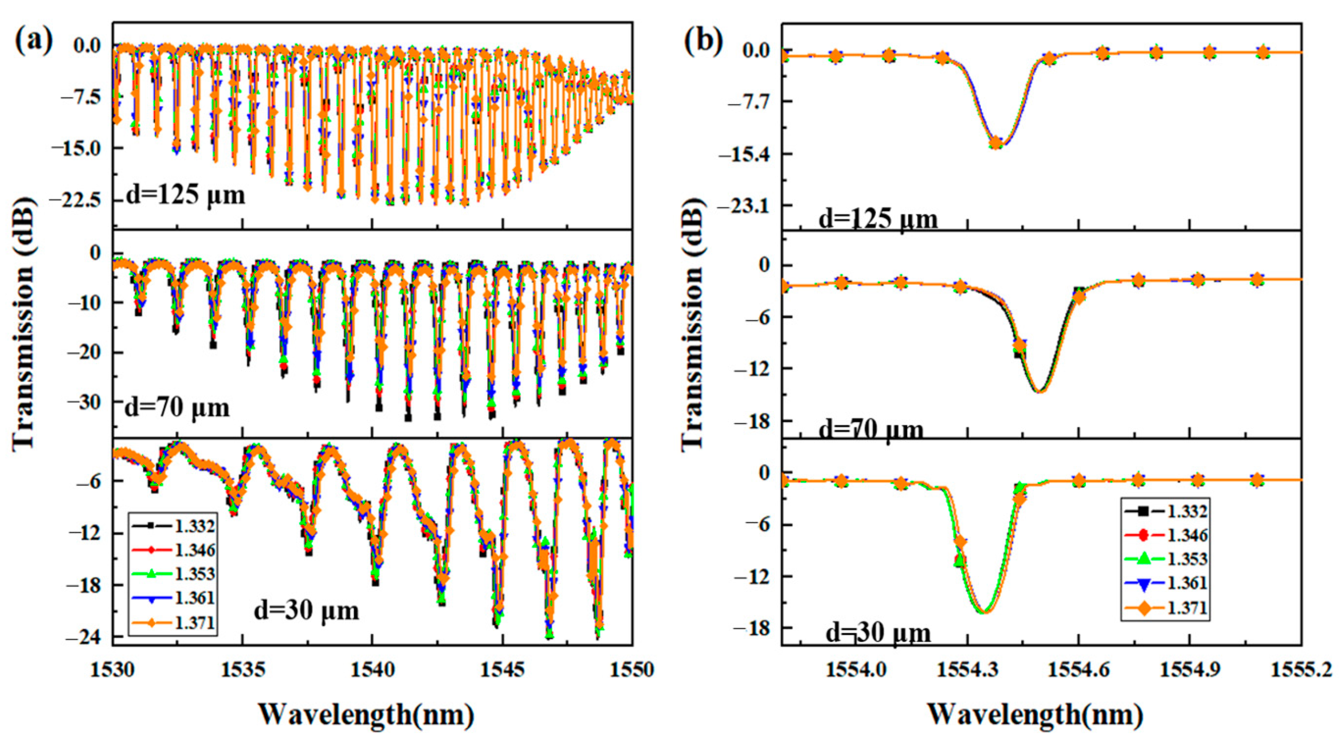
3.2. Sensing Performance Simulation

The tilt angle, grating period, grating length, and refractive index modulation depth are the most important structural parameters for a TMFBG. When the structural parameters change, the optical properties of the TMFBG will also change. The sensing model of the TMFBG is established using OptiFDTD 8.0 to study the influence of the cladding radius from the perspective of the energy distribution. In addition, the OptiGrating simulation module of the OptiWave 8.0 series software is used to study the transmission spectral response of the TMFBG under different refractive indices.
Figure 6 shows the simulation results regarding the refractive index sensing characteristics of the TMFBG when the refractive index of the external environment is changed from 1.34, 1.36, 1.38, and 1.40 to 1.42. The grating period is set to 0.53 μm. The tilt angle of the grating is 4°, and the modulation depth is 0.0001. When the ambient refractive index increases from 1.34 to 1.42, the cladding modes decrease gradually, and the high-order cladding modes disappear. This is because, as the ambient refractive index increases and gradually approaches the effective refractive index of the cladding, the higher-order cladding modes will leak into the external environment. When the ambient refractive index increases, the core mode of the TMFBG remains constant due to its wavelength location. This is consistent with mode coupling theory and the sensing characteristics of the TFBG structure. The core mode is insensitive to the change in the external refractive index, while the cladding mode is sensitive.
As shown in Figure 6b, when the ambient refractive index increases from 1.34 to 1.42, the cutoff wavelength is red-shifted. In practical applications, the refractive index can be detected by calibrating the drift value of the cutoff wavelength. When the refractive index ranges from 1.34 to 1.42, the cutoff wavelength shift of the TMFBG with the cladding diameter of 20 μm is ~40 nm. The refractive index sensitivity can be calculated as Δλ/Δn ≈ 5 nm/RIU.
The influence of various structural parameters of the TMFBG on the transmission spectra was studied and calculated using OptiGrating. It was seen that as the tilt angle of the TMFBG gradually increases, the core mode couples into radiation mode; the transmission depth of the core mode decreases; and the number of cladding modes increases. When the grating period of the TMFBG gradually increases, the resonance peaks will shift towards to the longer wavelengths, without any impact on the transmission intensity. As the length of the TMFBG gradually increases, the transmission depth of both core mode and cladding mode continuously strengthens. When the depth of refractive index modulation increases, it only affects the resonant depth of the TMFBG, without affecting the wavelength position. Simulation study of the sensing characteristics of the TMFBG on the refractive index indicates that as the refractive index increases, the core mode is unchanged, while the higher-order cladding mode continuously disappears. By calibrating the location of the cutoff wavelength, refractive index detection can be achieved. The spectra quality and sensing performance are determined by the structural parameters. To obtain a bigger signal-to-noise ratio or deeper resonance dips, it is needed for using a smaller grating inclination, the bigger refractive index modulation depth or the longer grating length. These three parameters do not need to be met simultaneously and can be appropriately balanced based on processing conditions. While the central wavelength is determined by the grating period. The refractive index sensing can be realized by tracing the locations of cutoff wavelength. Furthermore, the sensing sensitivity can be greatly improved by reducing the cladding diameter.

3.3. Fabrication and Sensing Experiment of Uniformly Etched TMFBG

3.3.1. Uniformly Etched TMFBG

The main parameters of the TFBG used in this study are as follows: the central wavelength is 1544 nm; the grating length is 10 mm; and the grating inclination is 8° (TFBG8-10, purchased from Shandong NuoGuang Photoelectric Technology Co., Ltd., Jinan, China). The TFBG is processed in a fume hood using the hydrofluoric acid chemical etching technique. The non-grating region of the TFBG is inserted into the quartz capillary and then fixed to the inner walls of the plastic vessels to ensure its structural stability, free from equipment vibration or fluid disturbances. Then, hydrofluoric acid with a volume concentration of 30% is dropped into the plastic container. To ensure a stable etching process, the dropped hydrofluoric acid must cover the entire grating area; meanwhile, a layer of liquid paraffin is used to cover the hydrofluoric acid to prevent its volatilization. The etched TMFBG is repeatedly washed with deionized water and dried to clear away any extra hydrofluoric acid.
Figure 7 compares the transmission spectra of the TFBG before etching and the etched TMFBG with the diameters of 70 μm and 30 μm. When the cladding thickness is thick enough (70 μm), the complete cladding mode envelope and high-quality transmission spectrum can be observed. At the same time, the core mode does not change, because the cladding is much thicker than the fiber core, inside which most of the energy is still strictly confined. The core mode is not yet affected by the decrease in the cladding thickness. When the diameter of the TMFBG becomes smaller, more energy from the cladding mode will be coupled to the external environment, resulting in a significant decrease in the number of cladding modes (30 μm).

3.3.2. Refractive Index-Sensing Characteristics

NaCl solutions with different concentrations (5%, 10%, 15%, 20%, 25%) were prepared by dissolving solid NaCl into distilled water. The corresponding refractive indices were determined (to be 1.332, 1.346, 1.353, 1.361, and 1.371, respectively) with an Abbe refractometer. The different concentrations of NaCl solutions were kept at room temperature for two hours to avoid the influence of temperature changes on the experiment. The refractive index measurement system is composed of an amplified spontaneous emission (ASE, working wavelength: 1525–1610 nm) and an optical spectrum analyzer (OSA). Three sizes of TMFBG structures, obtained after uniform etching, are studied at room temperature. After each measurement, the TMFBG structure is repeatedly cleaned with alcohol and dried to prevent the interference of the residual solution on the grating surface. The transmission spectra of the TMFBGs with different diameters in solutions with different refractive indices are recorded and compared in Figure 7.
As shown in Figure 8a, as the refractive index increases from 1.332 to 1.371, the resonance dip wavelength of the cladding mode increases. The wavelength shift of the TMFBG with a diameter of 30 μm is more obvious than that of the 70 μm and 125 μm TMFBGs. In addition to the wavelength shift, the resonant depth of the cladding modes also changes with the refractive index. When the refractive index continues to increase, the smaller-diameter etched TMFBG exhibits a greater wavelength shift and a smaller transmission depth for the cladding mode. As shown in Figure 8b, there are three core modes whose wavelength does not drift with the change in the refractive index. The transmission intensity of the core mode also does not change. The experimental results reveal that the core mode is insensitive to changes in the external refractive index, while the cladding mode shows the opposite effect.
The refractive index-sensing characteristic curves of the uniformly etched TMFBGs with the diameters of 125 μm (unetched), 70 μm, and 30 μm are shown in Figure 8. For the higher-order cladding mode at 1538 nm, when the diameter increases from 125 μm to 30 μm, the sensitivity is improved from 0.964 nm/RIU to 6.368 nm/RIU, as shown in Figure 9a. A smaller diameter corresponds to higher sensitivity. Compared with the raw TFBG, the refractive index sensitivity is increased more than six times. As shown in Figure 9b, the sensitivity of the low-order cladding mode at 1546 nm is low, and the sensitivity of the untreated TFBG is only 0.294 nm/RIU. When the cladding diameter is reduced to 30 μm, this sensitivity is increased to 2.353 nm/RIU, being approximately eight times higher. For the low-order cladding mode, the reduction in the cladding diameter has a more obvious effect in terms of improving the sensitivity. The binding ability of the optical fiber to the high-order cladding mode is weaker than that of the core mode, so the sensitivity of the low-order cladding mode is far lower than that of the high-order cladding mode. However, for both the low-order and high-order cladding modes, the decrease in the cladding diameter will improve their sensitivity to the refractive index change. High-sensitivity refractive index sensing can be achieved by measuring the wavelength shift of the higher-order cladding mode in the cladding mode.
In order to promote the proposed TMFBG sensor for monitoring building structural health and biological objects, the TMFBG can be encapsulated in flexible polymer materials with a large elasto-optic coefficient. The structural stress will directly affect the polymer encapsulation layer, leading to a change in its refractive index. In order to overcome the interference from the environmental random factors, such as temperature and humidity, two TMFBGs can be cascaded similar to traditional FBG pairs to achieve the simultaneous measurement for different physical qualities, including temperature, humidity, and stress. The cross-sensitivity among the different parameters can be effectively eliminated by demodulating the contributions of the different parameters to the refractive index sensitivity of the whole TMFBG sensing system.

4. Conclusions

The influence of the structural parameters of the TMFBG on its transmission spectrum was studied and calculated using OptiGrating. The tilt angle, grating length, and refractive index modulation depth will exert an impact on the transmission depth of the core modes and the number of cladding modes, while the grating period can determine the central wavelength of the light modes. The refractive index sensing can be completed by tracing the locations of the cutoff wavelength. The sensitivity of the TMFBG with the cladding diameter of 20 μm was calculated to be 5 nm/RIU. The uniformly etched TMFBG with the cladding diameters of 30 μm and 70 μm have been prepared by the capillary protecting method. The refractive index sensing performance of the prepared TMFBGs has been experimentally demonstrated. The refractive index sensitivities for the unetched TFBG and etched TMFBG with the diameter of 30 μm were compared. When the diameter increases from 125 μm to 30 μm, the sensitivity was improved from 0.964 nm/RIU to 6.368 nm/RIU for the higher-order cladding mode and from 0.294 nm/RIU to 2.353 nm/RIU for the lower-order cladding mode.

Author Contributions

Formal analysis, funding acquisition, methodology, investigation, and writing—original draft preparation, Y.Q.; conceptualization, writing—review and editing, supervision, and project administration, J.L. All authors have read and agreed to the published version of the manuscript.

Funding

This research was funded by Chang’an University, grant number 220241240091.

Institutional Review Board Statement

Not applicable.

Data Availability Statement

The raw data supporting the conclusions of this article will be made available by the authors on request.

Acknowledgments

In the Funding section, the project is titled, “The design and construction of renovation for old residential areas in Pingtan District”.

Conflicts of Interest

The authors declare no conflicts of interest.

References

  1. Lou, J.Y.; Wang, Y.P.; Tong, L.M. Microfiber Optical Sensors: A Review. Sensors 2014, 14, 5823–5844. [Google Scholar] [CrossRef] [PubMed]
  2. Hwang, I.K.; Kim, S.K.; Yang, J.K.; Kim, S.H.; Lee, S.H.; Lee, Y.H. Curved-microfiber photon coupling for photonic crystal light emitter. Appl. Phys. Lett. 2005, 87, 131107. [Google Scholar] [CrossRef]
  3. Sulaiman, A.; Harun, S.W.; Ahmad, H. Ring microfiber coupler erbium-doped fiber laser analysis. Chin. Opt. Lett. 2014, 12, 021403. [Google Scholar] [CrossRef]
  4. Vienne, G.; Li, Y.H.; Tong, L.M. Microfiber resonator in polymer matrix. IEICE Trans. Electron. 2007, E90c, 415–421. [Google Scholar] [CrossRef]
  5. Zhang, Q.; Zhu, T.; Zhang, J.D.; Chiang, K.S. Micro-Fiber-Based FBG Sensor for Simultaneous Measurement of Vibration and Temperature. IEEE Photonics Technol. Lett. 2013, 25, 1751–1753. [Google Scholar] [CrossRef]
  6. Yue, X.; Lu, R.Y.; Yang, Q.C.; Song, E.L.; Jiang, H.C.; Ran, Y.; Guan, B.O. Flexible Wearable Optical Sensor Based on Optical Microfiber Bragg Grating. J. Light. Technol. 2023, 41, 1858–1864. [Google Scholar] [CrossRef]
  7. Kou, J.L.; Ding, M.; Feng, J.; Lu, Y.Q.; Xu, F.; Brambilla, G. Microfiber-Based Bragg Gratings for Sensing Applications: A Review. Sensors 2012, 12, 8861–8876. [Google Scholar] [CrossRef] [PubMed]
  8. Her, S.C.; Chung, S.C. Dynamic Responses Measured by Optical Fiber Sensor for Structural Health Monitoring. Appl. Sci. 2019, 9, 2956. [Google Scholar] [CrossRef]
  9. Cao, S.F.; Chen, R.P.; Yang, Q.C.; He, X.; Chiavaioli, F.; Ran, Y.; Guan, B.O. Point-of-care diagnosis of pre-eclampsia based on microfiber Bragg grating biosensor. Biosens. Bioelectron. 2024, 249, 116014. [Google Scholar] [CrossRef]
  10. Wang, G.G.; Shum, P.P.; Ho, H.P.; Yu, X.; Hu, D.J.J.; Cui, Y.; Tong, L.M.; Lin, C.L. Modeling and analysis of localized biosensing and index sensing by introducing effective phase shift in microfiber Bragg grating (μFBG). Opt. Express 2011, 19, 8930–8938. [Google Scholar] [CrossRef]
  11. Ismaeel, R.; Lee, T.; Ding, M.; Belal, M.; Brambilla, G. Optical microfiber passive components. Laser Photonics Rev. 2013, 7, 350–384. [Google Scholar] [CrossRef]
  12. Yan, Z.Y.; Wang, J.J.; Wang, C.Y.; Yu, R.W.; Shi, L.; Xiao, L.M. Optical microfibers integrated with evanescent field triggered self-growing polymer nanofilms. Opt. Express 2022, 30, 18044–18053. [Google Scholar] [CrossRef] [PubMed]
  13. Zhang, Y.X.; Pu, S.L.; Li, Y.X.; Hao, Z.J.; Li, D.H.; Yan, S.K.; Yuan, M.; Zhang, C.C. Magnetic Field and Temperature Dual-Parameter Sensor Based on Nonadiabatic Tapered Microfiber Cascaded With FBG. IEEE Access 2022, 10, 15478–15486. [Google Scholar] [CrossRef]
  14. Zhang, Y.; Lin, B.; Tjin, S.C.; Zhang, H.; Wang, G.H.; Shum, P.; Zhang, X.L. Refractive index sensing based on higher-order mode reflection of a microfiber Bragg grating. Opt. Express 2010, 18, 26345–26350. [Google Scholar] [CrossRef] [PubMed]
  15. Liao, C.R.; Yang, K.M.; Wang, J.; Bai, Z.Y.; Gan, Z.S.; Wang, Y.P. Helical Microfiber Bragg Grating Printed by Femtosecond Laser for Refractive Index Sensing. IEEE Photonics Technol. Lett. 2019, 31, 971–974. [Google Scholar] [CrossRef]
  16. Li, L.J.; Jia, C.Y.; Xu, T.Z.; Ma, Q.; Sun, J.H. High stability microfiber Sagnac loop liquid refractive index sensor with FBG mode selecting. J. Instrum. 2022, 17, P11029. [Google Scholar] [CrossRef]
  17. Zhi, Y.Y.; Li, X.; Li, Y.P.; Li, J.; Guan, B.O. Superstructure microfiber grating characterized by temperature, strain, and refractive index sensing. Opt. Express 2020, 28, 8853–8861. [Google Scholar] [CrossRef] [PubMed]
  18. Ahmed, F.; Jun, M.B.G. Microfiber Bragg Grating Sandwiched Between Standard Optical Fibers for Enhanced Temperature Sensing. IEEE Photonics Technol. Lett. 2016, 28, 685–688. [Google Scholar] [CrossRef]
  19. Ran, Y.; Jin, L.; Tan, Y.N.; Sun, L.P.; Li, J.; Guan, B.O. High-Efficiency Ultraviolet Inscription of Bragg Gratings in Microfibers. IEEE Photonics J. 2012, 4, 181–186. [Google Scholar] [CrossRef]
  20. Riza, M.A.; Go, Y.I.; Harun, S.W.; Maier, R.R.J. FBG Sensors for Environmental and Biochemical Applications-A Review. IEEE Sens. J. 2020, 20, 7614–7627. [Google Scholar] [CrossRef]
  21. Singh, Y.; Raghuwanshi, S.K.; Prakash, O.; Saini, P.K. Design and development of tilted fiber Bragg grating (TFBG) chemical sensor with regression analysis of grating parameters for sensitivity optimization. Opt. Quant. Electron. 2021, 53, 664. [Google Scholar] [CrossRef]
  22. Qi, J. A comparison study of the sensing characteristics of FBG and TFBG. Sensor Rev. 2013, 33, 68–79. [Google Scholar] [CrossRef]
  23. Kameyama, A.; Katto, M.; Yokotani, A. Influence of the cladding diameter of optical fiber on the simultaneous measurement of the refractive index and temperature of liquids using tilted fiber Bragg grating. Jpn. J. Appl. Phys. 2016, 55, 068003. [Google Scholar] [CrossRef]
  24. Tomyshev, K.; Dolzhenko, E.I.; Butov, O.V. Correlation between optical fibre diameter and characteristics of tilted fibre Bragg grating-assisted sensors. Quantum Electron. 2021, 51, 1113–1117. [Google Scholar] [CrossRef]
  25. Yang, H.; Li, X.W.; Lei, M.; Ouyang, H.; Li, Y.L. TFBG Side Modes and Fresnel Reflection-Based Sensing System for Solution Concentration Measurement. IEEE Sens. J. 2023, 23, 6901–6909. [Google Scholar] [CrossRef]
  26. Korganbayev, S.; Sypabekova, M.; Amantayeva, A.; González-Vila, A.; Caucheteur, C.; Saccomandi, P.; Tosi, D. Optimization of Cladding Diameter for Refractive Index Sensing in Tilted Fiber Bragg Gratings. Sensors 2022, 22, 2259. [Google Scholar] [CrossRef]
Figure 1. Schematic of TMFBG structure: (a) detailed parameters and (b) FDTD simulation model.
Applsci 14 04707 g001
Figure 2. Transmission spectrum of TMFBG with grating inclinations of 4°, 5°, 6°, 7°, and 8°, respectively.
Applsci 14 04707 g002
Figure 3. Transmission spectrum of TMFBG at grating periods of 0.526 μm, 0.528 μm, 0.530 μm, 0.532 μm, and 0.534 μm.
Applsci 14 04707 g003
Figure 4. Transmission spectrum of TMFBG with grating lengths of 10 mm, 20 mm, 30 mm, 40 mm, and 50 mm, respectively.
Applsci 14 04707 g004
Figure 5. Transmission spectrum of TMFBG with grating refractive index modulation depths of 0.0001, 0.0002, 0.0003, 0.0004, and 0.0005, respectively.
Applsci 14 04707 g005
Figure 6. Simulation of refractive index sensing characteristics. (a) Transmission spectra of TMFBG and (b) the cutoff wavelength under different ambient refractive indices.
Applsci 14 04707 g006
Figure 7. Transmission spectra of TMFBGs with different cladding diameters.
Applsci 14 04707 g007
Figure 8. Transmission spectra of uniformly etched TMFBGs with different sizes, including their (a) local cladding mode and (b) core mode.
Applsci 14 04707 g008
Figure 9. Refractive index-sensing characteristic curve of uniformly etched TMFBGs with different diameters, showing (a) high-order cladding mode and (b) low-order cladding mode.
Applsci 14 04707 g009
Disclaimer/Publisher’s Note: The statements, opinions and data contained in all publications are solely those of the individual author(s) and contributor(s) and not of MDPI and/or the editor(s). MDPI and/or the editor(s) disclaim responsibility for any injury to people or property resulting from any ideas, methods, instructions or products referred to in the content.

