Article

Impact Wear Behavior of the Valve Cone Surface after Plasma Alloying Treatment

1
Weichai Power Co., Ltd., Weifang 261061, China
2
State Key Laboratory of Engine and Powertrain System, Weifang 261061, China
3
College of Materials Science and Technology, Nanjing University of Aeronautics and Astronautics, Nanjing 211106, China
4
National Engineering Research Center of Near-Net-Shape Forming for Metallic Materials, South China University of Technology, Guangzhou 510640, China
*
Author to whom correspondence should be addressed.
Appl. Sci. 2024, 14(11), 4811; https://doi.org/10.3390/app14114811
Submission received: 11 March 2024 / Revised: 20 May 2024 / Accepted: 28 May 2024 / Published: 2 June 2024
(This article belongs to the Section Surface Sciences and Technology)

Abstract

:
Valves are prone to wear under harsh environments, such as high temperatures and reciprocating impacts, which has become one of the most severe factors reducing the service life of engines. As a lightweight ceramic, CrN is considered an excellent protective material with high-temperature strength and resistance to wear. In this study, a CrN coating was applied onto the valve cone surface via double-layer glow plasma surface metallurgy technology. The formation process, microstructure, phase composition, hardness, and adhesion strength were analyzed in detail. Impact wear tests were conducted on the valve using a bench test device. The SEM and EDS results showed that the CrN coating evolved from an island-like form to a dense, cell-shaped surface structure. The thickness of the coating was approximately 46 μm and could be divided into a deposition layer and a diffusion layer, from the outer to the inner sections. The presence of element gradients within the diffusion layer proved that the coating and substrate were metallurgically bonded. The adhesion strength of the CrN coating measured via scratch method was as high as 72 N. The average Vickers hardness of the valve cone surface increased from 377.1 HV0.5 to 903.1 HV0.5 following the plasma alloying treatment. After 2 million impacts at 12,000 N and 650 °C, adhesive wear emerged as the primary wear mode of the CrN coating, with an average wear depth of 42.93 μm and a wear amount of 23.49 mg. Meanwhile, the valve substrate exhibited a mixed wear mode of adhesive wear and abrasive wear, with an average wear depth of 118.23 μm and a wear amount of 92.66 mg, being 63.7% and 74.6% higher than those of the coating. Thus, the CrN coating showed excellent impact wear resistance, which contributed to the enhancement of the service life of the valve in harsh environments.

1. Introduction

Valves are crucial components in engines, designed to open and close in a timely manner through the valve mechanism, thus ensuring the control of exhaust emissions in the cylinder [1]. However, due to the large amount of heat released by the combustion of fuel in a thermal engine, this heat cannot be quickly transferred outward, exposing valves to high-temperature conditions exceeding 600 °C. During the operation of the valve, reciprocating collisions between the cone surface and the valve seat occur. These significant impact forces result in severe wear of the cone surface, thereby reducing the service life of the valve [2,3]. The service condition, macroscopic structure, and impact wear failure of a valve are shown in Figure 1.
In recent years, the escalating demand for engine performance has promoted industrial progress, whereby valve wear and failure have increasingly became a crucial issue. In this respect, research focusing on valve protection has gained prominence [4,5]. It has been shown that the valve-seat friction pair endures harsh and complex conditions upon operation. Valves are prone to wear because of high load impact and high-temperature gas erosion, directly affecting the performance of the engine [2]. Forsberg et al. [6] pointed out that the repeated elastoplastic deformation of the valve will increase the dislocation density on the surface of the material under the impact of a high-frequency seating force. Moreover, the wear of the valve-seat friction pair will be aggravated in high-temperature and corrosive environments. Mufti et al. [7] have found that the two main factors affecting the performance of the valve train are friction and wear. Among them, energy loss caused by friction accounts for 10–20% of the engine output, and wear is the main cause of valve train failure.
Addressing the impact wear of valves, which initiates from the surface, entails the application of surface strengthening technologies. Preparing coatings with a favorable combination of properties on the surface of the valve represents an effective method to avoid the direct contact between the seat ring, the high-temperature gas, and the valve [8,9]. As a binary material, CrN has been widely applied in the field of surface protection. The atoms in CrN crystals are arranged in an interstitial phase face-centered cubic structure, ensuring excellent mechanical properties [10,11]. Chaochao et al. [12] prepared a CrN coating with a hardness of 18.84 GPa and Young’s modulus of 255.41 GPa on the surface of a metal valve seat via multi-arc ion plating technology. After surface strengthening, the friction coefficient and width and depth of wear scars were effectively reduced, improving the wear resistance of the valve seat significantly. Bobzin et al. [13] produced TiHFN/CrN nano-multilayer films and CrN composite multilayer films on the mold by means of DC magnetron sputtering technology. The results showed that the wear resistance of the mold was increased and the punching pressure was reduced during the forming process, thereby improving the service life of the mold. Atapour et al. [14] have established that a nitriding layer, formed at a temperature of 550 °C and comprising CrN, Fe4N, and Fe2-3N, can significantly enhance the wear resistance of valve materials. However, the studies on the impact wear behavior of CrN coatings at high temperatures are still scarce.
Double glow plasma surface metallurgy technology (referred to as “double glow technology”) represents a new type of surface strengthening method, with the technical principle shown in Figure 2. In this technology, argon atoms are excited and ionized under low-vacuum and high-energy conditions, decomposing into argon plasma and free electrons. In the presence of an electric field, argon plasma bombards the low-potential Cr target material, resulting in the continuous ejection of Cr atoms in the valve cone surface. The gradual heating of the valve cone surface under bombardment, in turn, increases the concentration of surface vacancy defects. Cr atoms further diffuse inward through these defects and penetrate the interior of the valve cone, forming a high-strength metallurgical bond between the coating and the valve. When the temperature reaches 500 °C, nitrogen is introduced into the furnace and easily diffuses into the valve, ensuring metal nitridation [15]. During the experiment, the temperature control was maintained through the circulation of cooling water to prevent excessive furnace temperatures from altering the phase structure of the valve, which could potentially affect the surface modification.
Double glow technology has been widely applied in industrial fields to improve the wear resistance, corrosion resistance, fatigue resistance, and high-temperature oxidation of metal materials [16,17,18]. In this study, the CrN coating was prepared using double glow technology to improve the impact wear resistance of the valve cone surface at high temperatures. By optimizing the process parameters, the uniform deposition and the appropriate thickness of the coating along with the absence of significant defects therein were achieved. The adhesion strength of the CrN coating was assessed via scratch method to characterize the peel resistance of metallurgical bonding under the high-load impact. The surface strengthening effect of the CrN coating was evaluated through microhardness and impact wear tests.

2. Experimental Procedure

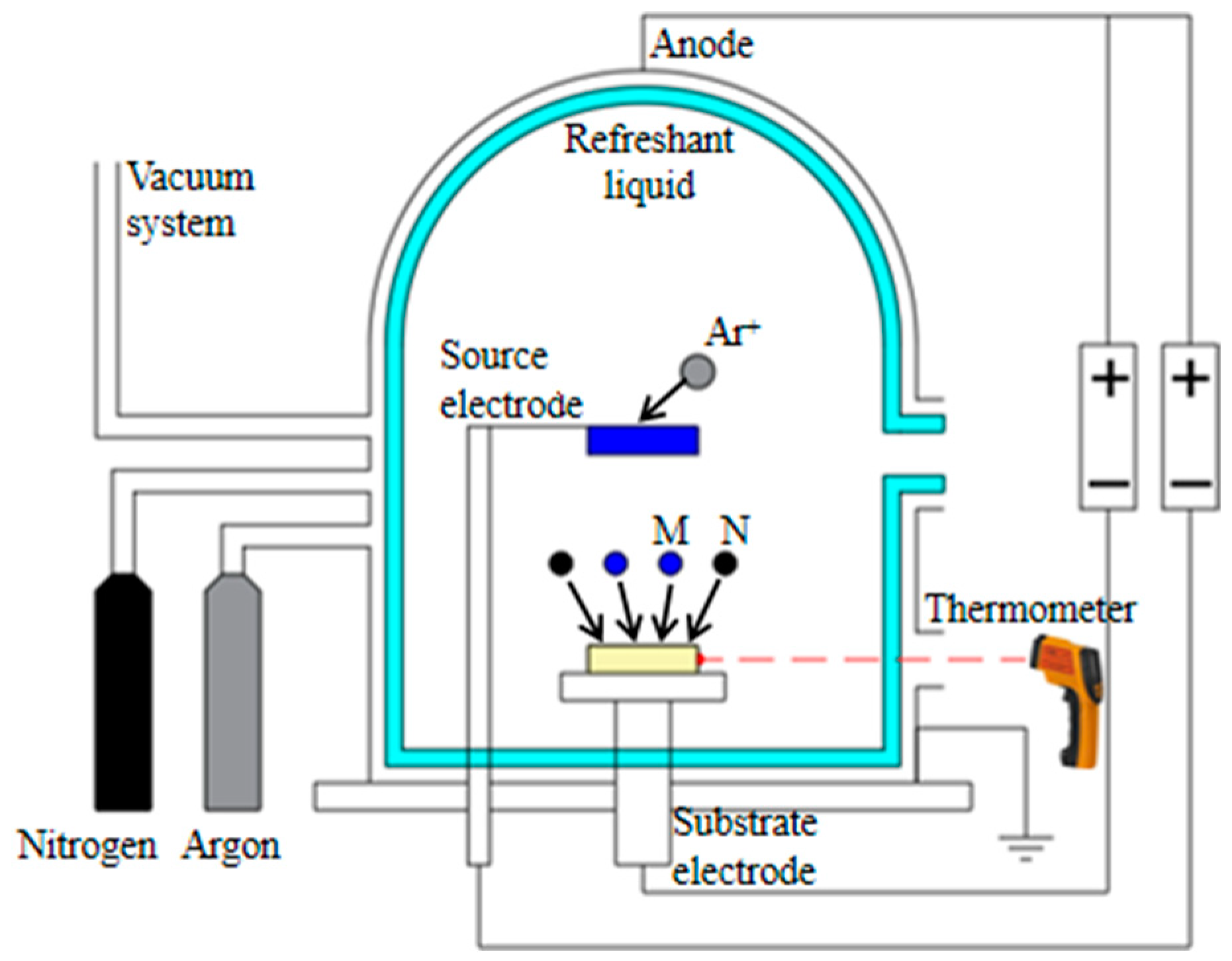
2.1. Preparation of CrN Coating

In this study, the CrN coating was produced as follows. The raw material for the experiment was NCF3015 valve alloy (Weichai Power Co., Ltd., Weifang, Shandong Province, China) with high international market recognition (the composition of the material is shown in Table 1) [19]. The shape and geometry parameters of the valve are given in Figure 3. The purity of the Cr target material was 99.95%. The valve underwent surface polishing treatment and was then immersed in a 70% industrial ethanol solution for 15 min ultrasonic cleaning to remove surface pollutants. After drying, it was placed in a plasma surface metallurgy furnace.
The preparation of the CrN coating involved the following steps. First, the mechanical pump was switched on to reduce the pressure to 0.1 Pa. Then, a pure argon gas was fed at a flow rate of 100 sccm, and the air pressure was stabilized at 32 Pa by adjusting the pumping rate of the mechanical pump. After that, a pulse negative bias of −800 V and −500 V was applied between the Cr target (source) and the substrate sample (cathode) with the anode, respectively, at a pulse frequency of 40 kHz. The source current was stabilized within 1.25 A by regulating the duty cycle of the bipolar power supply. The cathodic current was kept stable within 2.25 A. The electronic infrared thermometer was afterward used to monitor the furnace temperature. Once the furnace temperature reached 500 °C, argon and nitrogen gases were introduced at flow rates of 70 sccm and 30 sccm, respectively, by tuning the bipolar pulse voltage. The source current was stabilized within 1 A by adjusting the bipolar pulse voltage, and the cathode current was maintained at 1.6 A for 3 h after the nitrogen was supplied.

2.2. Microstructure Characterization Testing

The Scios2 scanning electron microscope (SEM) was used to capture the microscopic morphology of the coating surface and cross-section. The EDS detector equipped with a two-beam FIB system was employed for element scanning.

2.3. Microhardness and Adhesion Testing

The microhardness of the coating was assessed using a HVS-1000 microhardness tester (Bangyi Precision Measuring Instrument Co., Ltd., Shanghai, China) with a regular pyramid indenter with an angle of 136°. A load of 50 g was applied for 15 s. Five points on the surface of the sample were randomly selected, ensuring that the diagonal length of the indentation at the test points was sufficient for differentiation to reduce testing errors. After unloading, the hardness of the five points was automatically calculated by measuring the diagonal size of the indentation as follows:
H V = 0.102 × 2 F sin α 2 d 2
where HV represents the microhardness (HV0.5), F represents the loading load (N), α = 136°, and d is the average diagonal length of the indentation (mm).
A WS-2005 automatic scratch tester was employed to determine the adhesion strength of the CrN coating using a diamond indenter with a 120° cone shape and a top radius of 0.2 mm. During the measurement, the indenter was applied perpendicular to the surface of the coating, and the pressure on the indenter was gradually increased until the coating peeled off. The sample was driven by a spiral apparatus and slid slowly along a straight line relative to the indenter. The pressure at which the coating peeled off was assumed to be a critical load Lc, which reflected the peeling resistance of the coating and was used to characterize the adhesion strength between the coating and the substrate. During the loading process, the acoustic signals generated upon scratching were collected by the sensor and amplified by the PC to obtain their variation with pressure. The testing temperature was set at 25 °C and the loading rate was 10 N/min.

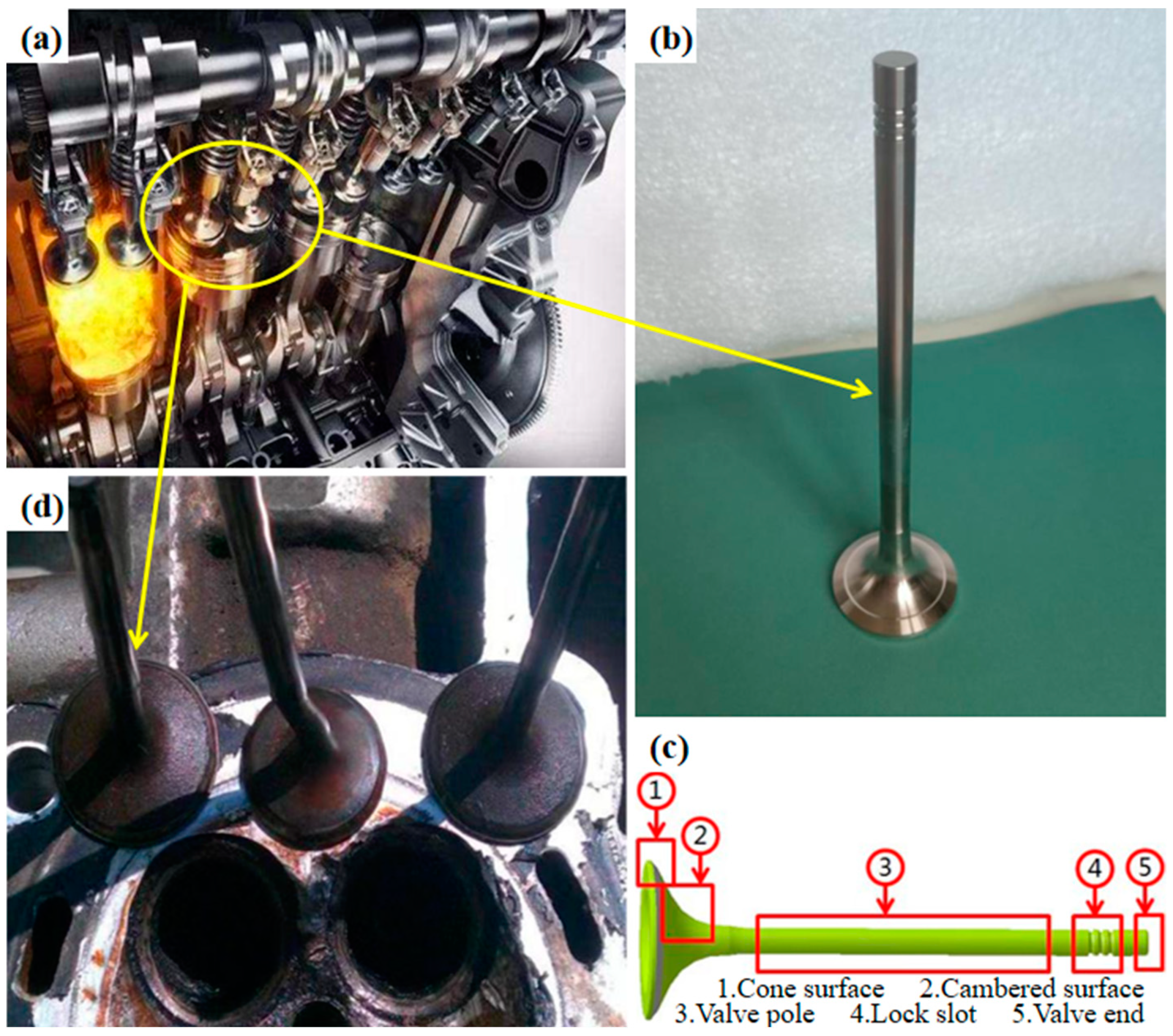
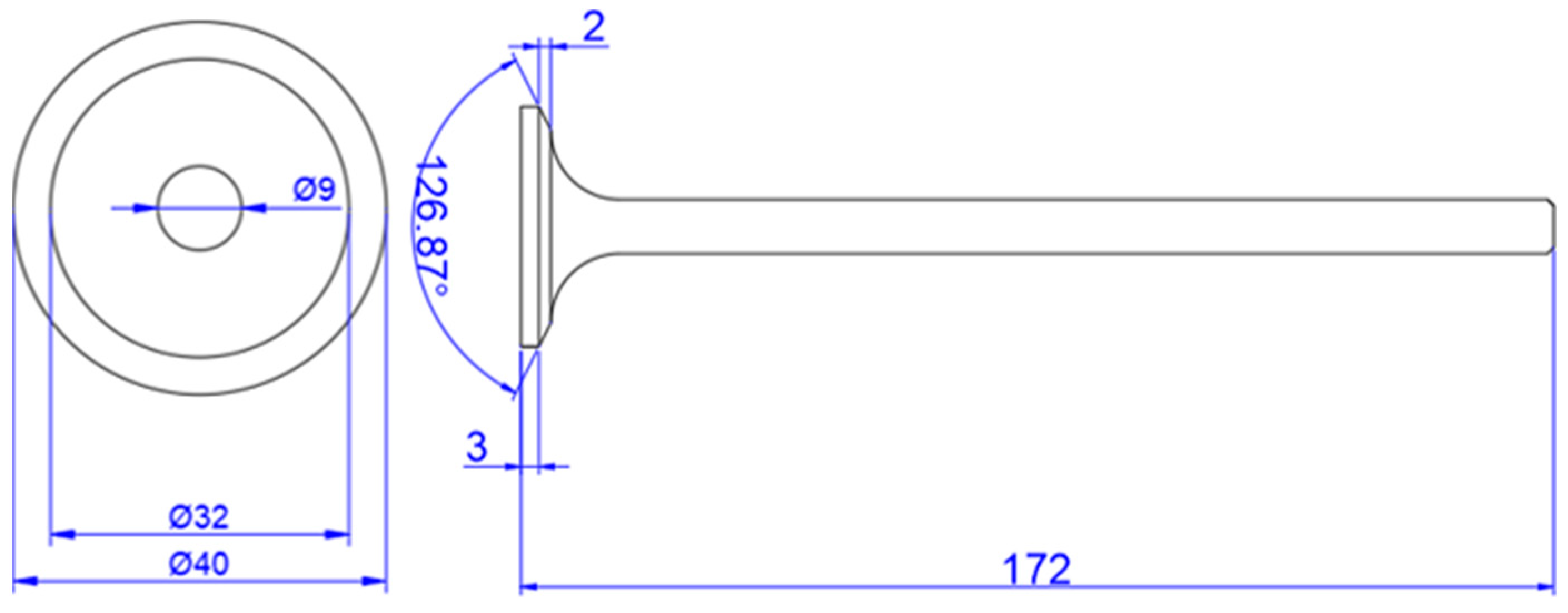
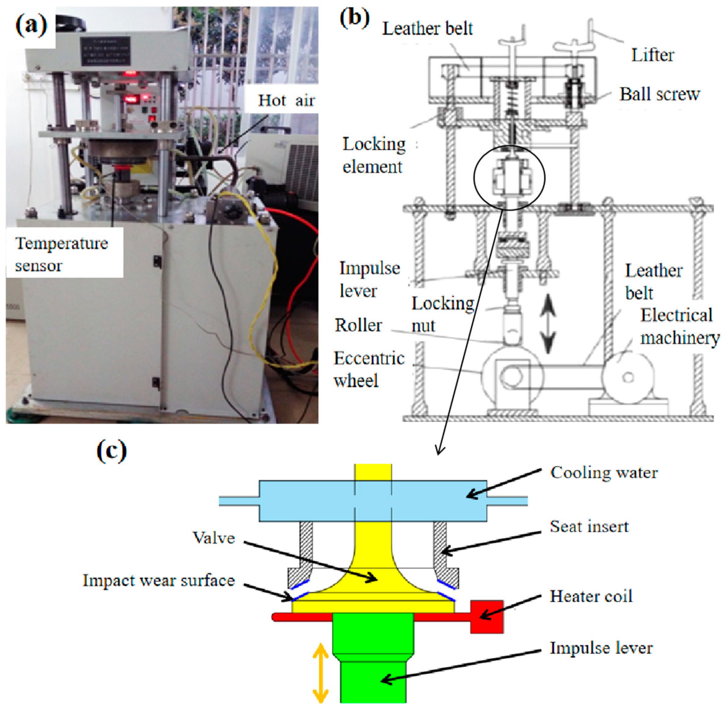
2.4. Impact Wear Testing

The impact wear test was conducted using a self-designed valve-seat impact test bench device. The equipment and its operation principle are illustrated in Figure 4. The test bench could fully simulate the actual working environment of a valve-seat friction pair, offering a simple structure, high reliability, and easy disassembly and assembly. After applying mechanically the impact force, the valve was driven up and down by the motor to realize the impact between the seat ring and the valve cone surface. When the center point of the eccentric wheel was in its lowest position, the valve was open, and the eccentric wheel turned over at a certain angle, causing the impact rod to lift the valve and impact the seat at a certain speed. Then, the closing state of the valve simulated the gas pressure after the valve was seated. Once the eccentric wheel rotated to the low position again, the valve opened under a spring force and entered the next cycle. The test parameters based on the actual working environment of the valve are shown in Table 2 [20]: temperature of 650 °C, load of 12,000 N, impact frequency of 10 Hz, and impact frequency of 2 million times. The wear mechanism was analyzed by comparing the abrasion morphology, contour, and wear amount of the valve before and after the coating preparation.

3. Results and Discussion

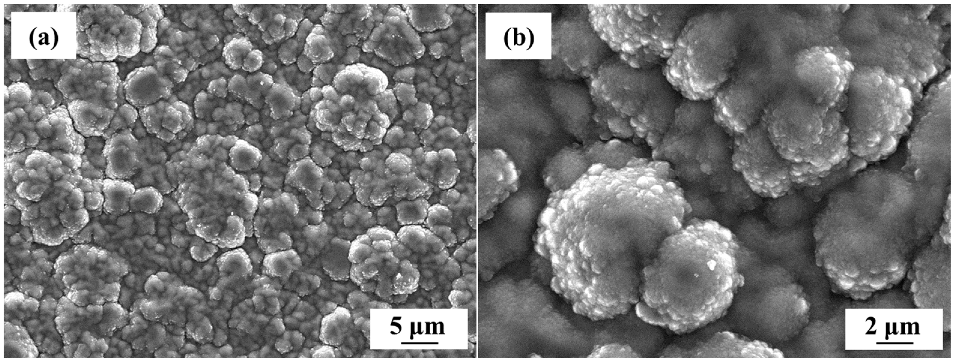
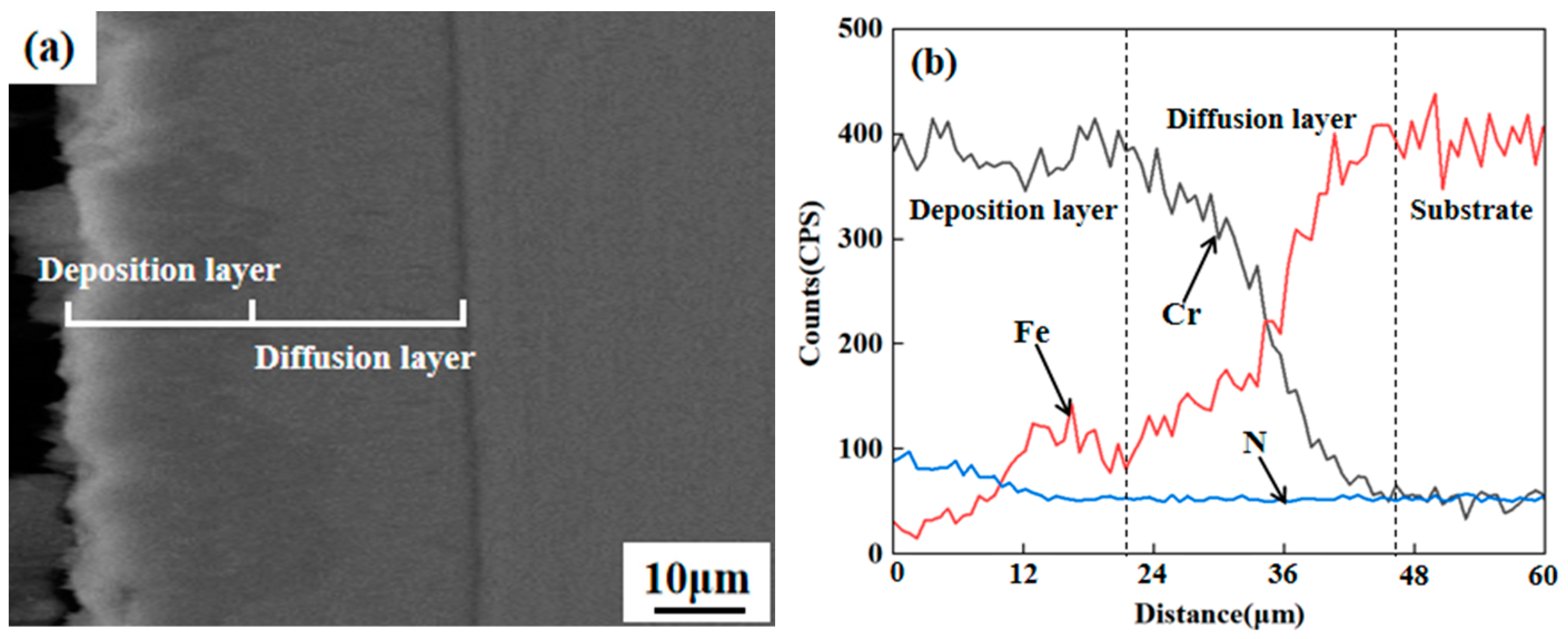
3.1. Microstructural Characterization

The surface microscopic morphology of the CrN coating is shown in Figure 5. The cell bulge structure on the surface indicates that the coating has grown in an island manner. According to Figure 5a, the coating grew evenly without cracks, pores, or any other defects. The initial cell particle diameter ranges from 1 to 5 μm and is evenly distributed on the surface of the sample, contributing to the fine crystal reinforcement effect. As shown in Figure 5b, after nucleation on the surface of the coating, the core surface grew through the atomic diffusion, forming a cell tissue with smaller particles and incorporating the new precipitation phase as the core.
The cross-sectional microscopic morphology and composition distributions of the CrN coating are shown in Figure 6. As can be seen from Figure 6a, the coating possesses a smooth and dense structure with a thickness of about 46 mm, without cracks or hole defects. It can be divided into deposition and diffusion layers from the outside to the inside. The outer surface of the deposition layer shows fluctuations within 1 μm due to the cell bulge structure. There are signs of layered accumulation and growth from the middle position of the deposition layer to the outer surface. A component transition exists between the diffusion and deposition layers, where the lattice distortion is significant because of the boundary phenomenon. Based on its location, the boundary has an irregular wave shape, and the thickness of the deposition layer is approximately 21 μm. The boundary between the diffusion layer and the substrate is uniform, forming a high-strength metallurgical bond, which effectively improves the service stability of the valve under high-temperature conditions [21]. As shown in Figure 6b, the diffraction intensity of chromium in the deposition layer fluctuates normally, while that of nitrogen gradually decreases from 100 CPS, indicating that chromium atoms were evenly deposited on the coating, while the diffusion of nitrogen atoms into the coating gradually decreased. In the diffusion layer, the diffraction intensity of chromium decreases, while that of iron shows a gradual increase, creating a transition layer between the deposition layer and the substrate. The integration of the CrN coating with the valve substrate through metallurgical methods reduces the thermal expansion coefficient difference and the degree of lattice distortion, thereby preventing large-amplitude cracking under high-temperature conditions.

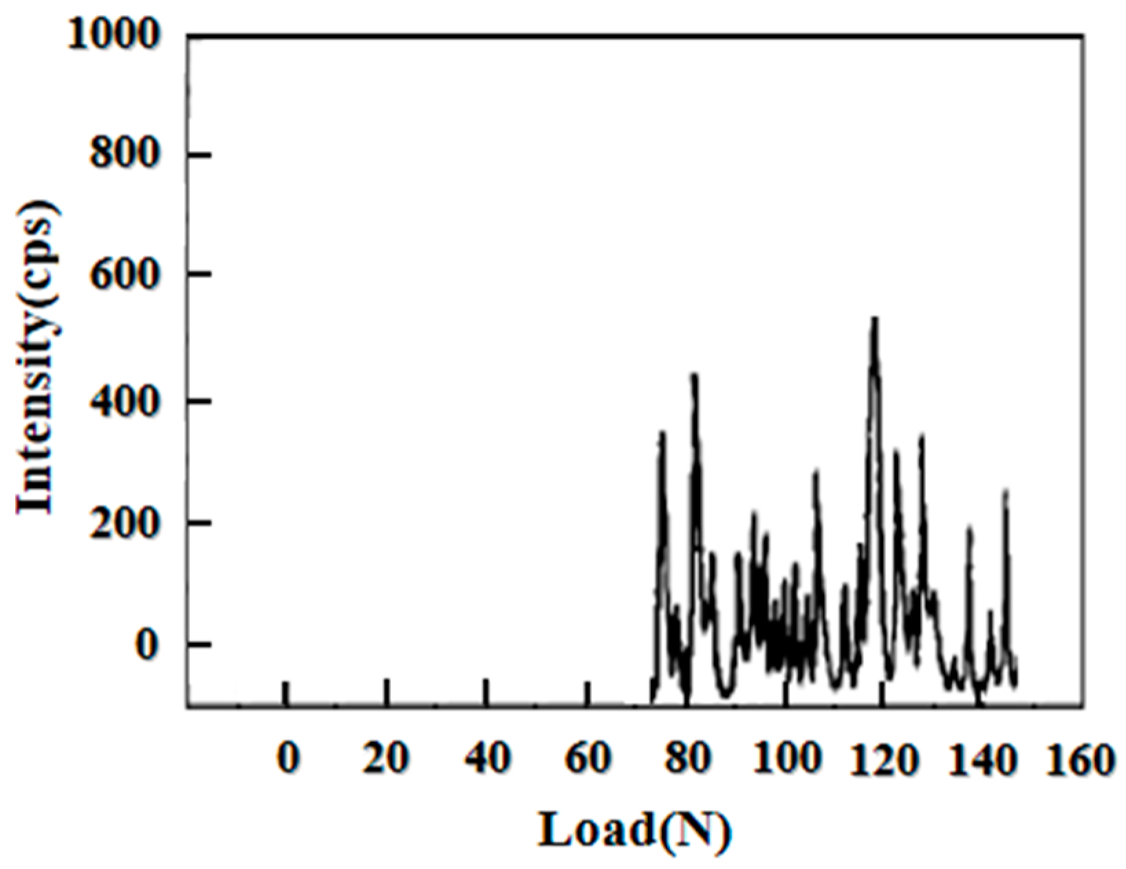
3.2. Microhardness and Adhesion

The hardness test results are summarized in Table 3. According to the data, the average surface hardness of the valve substrate is 377.1 HV0.5, while that of the CrN coating reaches 903.1 HV0.5. This significant increase (by approximately 2.4 times) can be attributed to the fact that chromium as a transition metal element can form an interstitial phase crystal structure with highly electronegative non-metallic nitrogen. In this structure, the chromium atoms are organized into a face-centered cubic configuration, and the nitrogen atoms are mainly arranged in the gaps within the octahedron, resulting in strong atomic bonding and, consequently, high hardness [22].
The adhesion test results are presented in Figure 7. At the initial stage of testing, the scratch depth was shallow, and the indenter slid smoothly on the coating surface without generating any acoustic signals. Once the load increased to 72 N, the coating underwent local rupture, and acoustic signals were generated, indicating that the Lc value of the coating was approximately 72 N. With a further increase in the load, the acoustic signals fluctuated continuously in the form of peaks, demonstrating the constant cracking and peeling off of the CrN coating.

3.3. Impact Wear

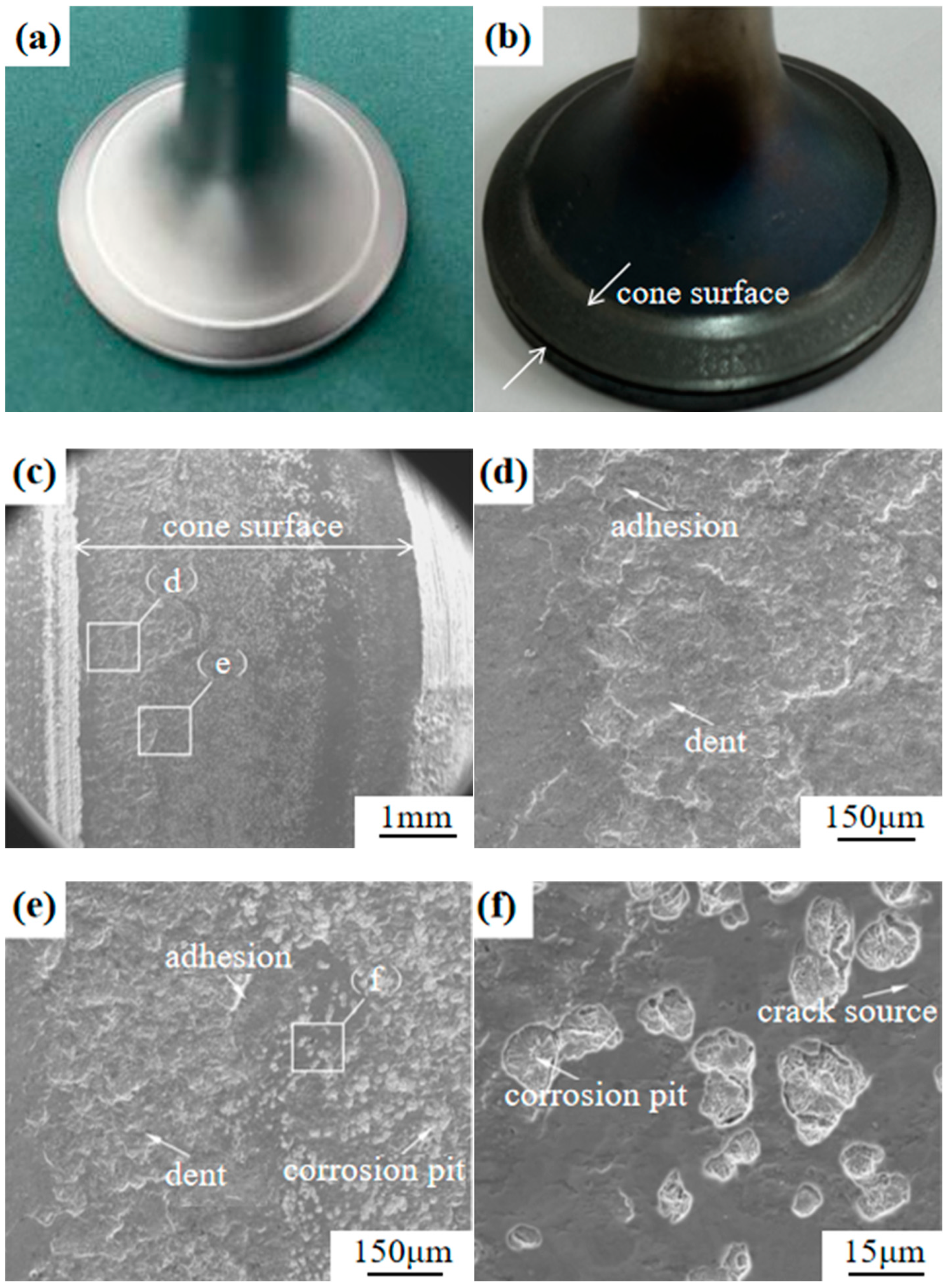
3.3.1. Wear Morphology

The macroscopic morphology of the valve substrate before and after wear is shown in Figure 8a,b, and its microscopic morphology is depicted in Figure 8c–f. Initially, the valve surface exhibits a metallic luster after machining, characterized by minimal roughness and a conical area mirroring a polished surface. Following the impact wear, the valve loses its original luster whereby the neck turns dark blue and the conical surface becomes black brown. This alteration occurs due to the high-temperature oxidation throughout the testing, altering the material’s structure and composition [23]. Figure 8c displays the flat wear surface of the substrate, with significant adhesion in the area near the neck of the substrate. Figure 8d–f reveal extensive grinding and adhesion on the surface alongside furrows and cracks. These phenomena result from the repeated high-load impacts inducing internal defects and microcracks. These cracks extend, connecting to the valve surface and leading to the material peel-off under the axial force, which causes adhesion between the valve and seat surfaces. After grinding, debris transform into hard particles at high temperatures, creating furrows on the surface of the substrate [24].
The macroscopic and microscopic morphologies of the CrN coating before and after wear are shown in Figure 9a,b and Figure 9c–f, respectively. The roughness of the coating is higher than that of the valve substrate, presenting a slightly frosted appearance. As depicted in Figure 9c, the valve cone remains relatively smooth without notable gullies or fluctuations, yet it is covered with a large area of peeling pits, and there are adhesive characteristics in the area near the valve neck. Figure 9d–f indicate that these peeling pits are primarily round or oval and are small in size. This is attributed to the discontinuous contact of the surface during the prolonged high-temperature impact tests. Consequently, when the surface load and stress cycle reach a certain threshold, fatigue phenomena emerge on the contact surfaces of the valve or seat, leading to material cracks and peel-off, which subsequently induces the formation of abrasive chips [25].

3.3.2. Wear Amount

The wear surfaces of the valve substrate and CrN coating were scanned within a range of 0–270° at a step of 90° using a laser level. The contours of four wear surfaces were measured as depicted in Figure 10. Two horizontal lines denote the average depth of the contour before and after the test, with the difference representing the average wear depth. Figure 8a–d illustrate the valve profile before and after the contact between the valve base and its counterpart, while Figure 10e–h show the valve profile before and after the contact between the CrN coating and the seat pair. As can be seen from Figure 10, the contour curve before the test comprises two sections: a rapidly rising oblique contour and a horizontal contour. The horizontal contour corresponds to the cone area in contact with the seat, and the oblique contour is ascribed to the neck transition area of the valve, in which wear predominantly occurs. Initially, the horizontal contour of the valve substrate appears neat with minimal fluctuation, indicating low surface roughness; conversely, the horizontal contour of the CrN coating exhibits slight fluctuations, reflecting the microscopic surface morphology, which is consistent with the island growth regularity of the coating. During the test, the valve is subjected to the impact load from the spring and the burst pressure in the cylinder, leading to severe plastic deformation and radial flow. The acceleration of the circulating seat generates a shock load on the valve cone, causing periodic shear stress and contact stress, which leads to the wear and the notable increase in roughness of the valve surface. The wear depth of the valve substrate first increases and then gradually decreases, with the depth of the contour line significantly increasing after the test, which suggests a slow and stable deepening of the CrN wear depth of the coating below that of the valve substrate. This indicates the high hardness and good wear resistance of the coating [26].
Before and after the test, the valve neck was completely immersed in absolute ethanol, and an ultrasonic cleaning machine was used to remove oil and impurities from the surface. After drying, the mass of the valve was determined using an electronic analytical balance to calculate the difference in mass before and after the test, thus determining the wear amount. The depth and amount of wear marks are listed in Table 4. According to the data, the wear depth was similar at the four positions of the CrN coating, with the maximum difference of 15 μm, indicating that the valve was evenly stressed during the bench impact wear test. After 2 million shocks, the average wear depth and the wear amount of the coating sample were 42.93 μm and 23.49 mg, respectively, i.e., 63.7% and 74.6% lower than those of the valve substrate (118.23 μm and 92.66 mg, respectively), demonstrating the effective protection provided by the CrN coating.

4. Conclusions

Using double glow technology, highly resistant CrN coatings were prepared on the NCF3015 valve surface, enhancing the service stability of the latter. The surface microstructure was characterized via scanning electron microscopy (SEM) and energy dispersive spectroscopy (EDS). The microhardness was examined using a Vickers hardness tester. The adhesion strength was assessed by the scratching method. The impact wear behavior of the valve was studied by means of a bench test device. Based on the findings, the following conclusions can be drawn.
(1) Under the set experimental parameters, the CrN coating develops in an island-like formation, achieving a thickness of approximately 46 μm. The metal Cr shows a gradient distribution in the diffusion layer and forms a high-strength metallurgical bond with the substrate, exhibiting an adhesion of approximately 72 N.
(2) The average surface hardness of the CrN coating reaches 903.1 HV0.5, exceeding the hardness of the valve substrate by approximately 2.4 times. This is mainly attributed to the interstitial phase structure of CrN with a face-centered cubic configuration. The high hardness also enhances the impact resistance of the CrN coating.
(3) After exposure to a temperature of 650 °C under a load of 12,000 N over 2 million shocks, the CrN coating and its seat primarily exhibit adhesive wear along with local fatigue peel, whereas the wear mechanism between the valve substrate and its seat involves both adhesive and abrasive wear mechanisms. The average wear depth and wear amount of CrN coating are found to be 42.93 μm and 23.49 mg, respectively, being 63.7% and 74.6% lower than those of the substrate (118.23 μm and 92.66 mg, respectively).

Author Contributions

Conceptualization, C.L., Y.Y. and D.W.; methodology, M.L. and P.Z.; software, C.L. and M.L.; validation, C.L., D.W. and P.Z.; formal analysis, Y.Y.; investigation, C.L., D.W. and S.Q.; resources, C.L. and S.Q.; data curation, M.L.; writing—original draft preparation, C.L., Y.Y. and M.L.; writing—review and editing, C.L., D.W. and P.Z.; visualization, D.W.; supervision, C.L.; project administration, C.L. All authors have read and agreed to the published version of the manuscript.

Funding

This project was supported by the Natural Science Foundation for Excellent Young Scientists of Jiangsu Province, China (Grant No. BK20180068), and Fundamental Research Funds for the Central Universities, China (Grant No. NT2022019), Open Project Funding for State Key Laboratory of Engine and Powertrain System, China (Grant No. skleps-sq-2023-080).

Data Availability Statement

The data presented in this study are available in the article.

Acknowledgments

The equipment for this project was supported by Plasma Surface Engineering Laboratory.

Conflicts of Interest

Authors Changzeng Luo and Yajun Yao were employed by the company Weichai Power Co., Ltd. The remaining authors declare that the research was conducted in the absence of any commercial or financial relationships that could be construed as a potential conflict of interest.

References

  1. Chun, K.-J.; Kin, J.H.; Hong, J.S. A study of exhaust valve and seat insert wear depending on cycle numbers. Wear 2007, 263, 1147–1157. [Google Scholar] [CrossRef]
  2. Slatter, T.; Taylor, H.; Lewis, R.; King, P. The influence of laser hardening on wear in the valve and valve seat contact. Wear 2009, 267, 797–806. [Google Scholar] [CrossRef]
  3. Singh, H.; Jain, P.K. A comparative study of precision finishing of rebuild engine valve faces using micro-grinding and ECH. J. Remanuf. 2015, 5, 6. [Google Scholar] [CrossRef]
  4. Liu, S.-Y.; Hu, J.-D.; Wang, H.-Y.; Guo, Z.-X.; Yu, C.; Chumakov, A.N.; Bosak, A. A study on microstructures and properties of P/M valve seats of hot forging by laser irradiation. Opt. Laser Technol. 2007, 39, 758–762. [Google Scholar] [CrossRef]
  5. Salgado, L.; Jesus Filho, E.S.; Jesus, E.R.B.; Rossi, J.L.; Santos, J.A.; Colosio, M.A. Mechanical and microstructural characterisation of P/M high-speed steel valve seat inserts. Mater. Sci. Forum 2003, 416–418, 312–316. [Google Scholar] [CrossRef]
  6. Forsberg, P.; Gustasson, F.; Hollman, P.; Jacobson, S. Comparison and analysis of protective tribofilms found on heavy duty exhaust valves from field service and made in a test rig. Wear 2013, 302, 1351–1359. [Google Scholar] [CrossRef]
  7. Mufti, R.A.; Jefferies, A. Novel method of measuring tappet rotation and the effect of lubricant rheology. Tribol. Int. 2008, 41, 1039–1048. [Google Scholar] [CrossRef]
  8. Motahari-Nezhad, M.; Mazidi, M.S. An Adaptive Neuro-Fuzzy Inference System (ANFIS) model for prediction of thermal contact conductance between exhaust valve and its seat. Appl. Therm. Eng. 2016, 105, 613–621. [Google Scholar] [CrossRef]
  9. Fujiki, A.; Oyanagi, M.; Miyazawa, T.; Fujitsuka, H.; Kawata, H. Tougher valve seats use two hard particles but no cobalt. Met. Powder Rep. 2005, 60, 20–22. [Google Scholar] [CrossRef]
  10. Yao, S.-H.; Su, Y.-L. The tribological potential of CrN and Cr(C, N) deposited by multi-arc PVD process. Wear 1997, 212, 85–94. [Google Scholar] [CrossRef]
  11. Wang, D.; Lin, S.-S.; Yang, Z.; Yin, Z.-F.; Ye, F.-X.; Gao, X.-Y.; Qiao, Y.-P.; Xue, Y.-N.; Yang, H.-Z.; Zhou, K.-S. Failure mechanisms of CrN and CrAlN coatings for solid particle erosion resistance. Vacuum 2022, 204, 111–113. [Google Scholar] [CrossRef]
  12. Ji, C.-C.; Guo, Q.-Q.; Li, J.-P.; Guo, Y.-C.; Yang, Z.; Yang, W.; Xu, D.-P.; Yang, B. Microstructure and properties of CrN coating via multi-arc ion plating on the valve seat material surface. J. Alloys Compd. 2022, 891, 161966. [Google Scholar] [CrossRef]
  13. Bobzin, K.; Bagcivan, N.; Immich, P.; Warnke, C.; Klocke, F.; Zeppenfeld, C.; Mattfeld, P. Advancement of a nanolaminated TiHfN/CrN PVD tool coating by a nano-structured CrN top layer in interaction with a biodegradable lubricant for green metal forming. Surf. Coat. Technol. 2009, 203, 3184–3188. [Google Scholar] [CrossRef]
  14. Atapour, M.; Ashrafizadeh, F. Tribology and cyclic oxidation behavior of plasma nitrided valve steel. Surf. Coat. Technol. 2008, 202, 4922–4929. [Google Scholar] [CrossRef]
  15. Xu, Z.; Liu, X.; Zhang, P.; Zhang, Y.; Zhang, G.; He, Z. Double glow plasma surface alloying and plasma nitriding. Surf. Coat. Technol. 2007, 201, 4822–4825. [Google Scholar] [CrossRef]
  16. Zhang, P.; Xu, Z.; Zhang, G.; He, Z. Surface plasma chromized burn-resistant titanium alloy. Surf. Coat. Technol. 2007, 201, 4884–4887. [Google Scholar] [CrossRef]
  17. Wei, D.-B.; Li, F.-K.; Li, S.-Q.; Chen, X.-H.; Ding, F.; Zhang, P.-Z.; Wang, Z.-Z. A New Plasma Surface Alloying to Improve the Wear Resistance of the Metallic Card Clothing. Appl. Sci. 2019, 9, 1849. [Google Scholar] [CrossRef]
  18. Chen, Z.; Wu, W.; Cong, X. Oxidation resistance coatings of Ir-Zr and Ir by double glow plasma. J. Mater. Sci. Technol. 2014, 30, 268–274. [Google Scholar] [CrossRef]
  19. Hawryluk, M.; Lachowicz, M.; Janik, M.; Ziemba, J.; Gronostajski, Z. Preliminary studies of increasing the durability of forging tools subjected to various variants of surface treatment used in the hot die forging process of producing valve forgings. Eng. Fail. Anal. 2023, 143, 106886. [Google Scholar] [CrossRef]
  20. Qu, S.-G.; Li, J.-H.; Li, D.-A.; Sun, P.-F.; Li, X.-Q.; Sun, G.; Luo, C.-Z. Exploring the impact and mechanism of hardfacing STL12 on impact wear performance at high temperature and heavy load. Surf. Coat. Technol. 2024, 477, 130385. [Google Scholar] [CrossRef]
  21. Li, Z.; Liu, C.-H.; Chen, Q.-S.; Yang, J.-J.; Liu, J.-M.; Yang, H.-Y.; Zhang, W.; Zhang, R.-Q.; He, L.-X.; Long, J.-P.; et al. Microstructure, high-temperature corrosion and steam oxidation properties of Cr/CrN multilayer coatings prepared by magnetron sputtering. Corros. Sci. 2021, 191, 109–115. [Google Scholar] [CrossRef]
  22. Mayrhofer, P.H.; Rovere, F.; Moser, M.; Strondl, C.; Tietema, R. Thermally induced transitions of CrN thin films. Scr. Mater. 2007, 57, 249–252. [Google Scholar] [CrossRef]
  23. Straffelini, G.; Trabucco, D.; Molinari, A. Oxidative wear of heat-treated steels. Wear 2001, 250, 485–491. [Google Scholar] [CrossRef]
  24. Fox-Robinovich, G.S.; Ymomoto, K.; Veldhuis, S.C.; KovalevA, I.; Dosbaeva, G.K. Tribological adaptability of TiAlCrN PVD coatings under high performance dry machining conditions. Surf. Coat. Technol. 2015, 200, 1804–1813. [Google Scholar] [CrossRef]
  25. Rahman, M.M.; Jiang, Z.-T.; Zhou, Z.-F.; Xie, Z.-H.; Yin, C.-Y.; Kabir, H.; Haque, M.M.; Amri, A.; Mondinos, N.; Altarawneh, M. Effects of annealing temperatures on the morphological, mechanical, surface chemical bonding, and solar selectivity properties of sputtered TiAlSiN thin films. J. Alloys and Compd. 2016, 671, 254–266. [Google Scholar] [CrossRef]
  26. Gore, G.J.; Gates, J.D. Effect of hardness on three very different forms of wear. Wear 1997, 203–204, 544–563. [Google Scholar] [CrossRef]
Figure 1. (a) Service condition, (b,c) macroscopic structure, and (d) impact wear failure of a valve.
Applsci 14 04811 g001
Figure 2. Schematic diagram of the double glow technology.
Applsci 14 04811 g002
Figure 3. Shape and geometry parameters of the valve.
Applsci 14 04811 g003
Figure 4. Bench test device diagram. (a) Platform equipment, (b,c) working principle of bench equipment.
Applsci 14 04811 g004
Figure 5. Surface topography of the CrN coating at (a) 2000×, and (b) 5000× magnification.
Applsci 14 04811 g005
Figure 6. Section of CrN coating. (a) Section morphology; (b) element distribution.
Applsci 14 04811 g006
Figure 7. Acoustic signals of CrN coating.
Applsci 14 04811 g007
Figure 8. Wear morphology of the valve substrate. (a) before wear; (b) after wear; (c) microscopic morphology of cone surface; (d,e) enlarged area in Figure 8c; (f) enlarged area in Figure 8e.
Applsci 14 04811 g008
Figure 9. Wear morphology of CrN coating. (a) before wear; (b) after wear; (c) microscopic morphology of cone surface; (d,e) enlarged area in Figure 8c; (f) enlarged area in Figure 8e.
Applsci 14 04811 g009
Figure 10. Wear contour morphology. (ad) Valve substrate; (eh) CrN coating.
Applsci 14 04811 g010aApplsci 14 04811 g010b
Table 1. NCF3015 valve alloy composition.
ElementNiCrTiAlSiMnMoNbCuCElse
wt/%30–33.513.5–15.52.3–2.91.6–2.20–0.50–0.50.4–10.4–0.90–0.50–0.08Little
Table 2. Test equipment parameters.
TemperatureLoadImpact FrequencyStroke Length
650 °C12,000 N10 HZ0–20 mm
Table 3. Hardness test results of samples (HV0.5).
Point 1Point 2Point 3Point 4Point 5Average
Substrate371.4378.6380.3369.5385.7377.1
CrN914.6922.0879.1905.3894.7903.1
Table 4. Depth and amount of wear marks.
0°/μm90°/μm180°/μm270°/μmAverage/μmWear Amount/mg
Valve substrate119.88114.82116.67121.53118.2392.66
CrN coating49.8243.4143.6334.8642.9323.49
Disclaimer/Publisher’s Note: The statements, opinions and data contained in all publications are solely those of the individual author(s) and contributor(s) and not of MDPI and/or the editor(s). MDPI and/or the editor(s) disclaim responsibility for any injury to people or property resulting from any ideas, methods, instructions or products referred to in the content.

