Abstract
Autonomous underwater vehicles (AUVs) commonly use screw propellers to move in a water environment. However, compared to the propeller-driven AUV, bio-inspired AUVs feature a higher energy efficiency, longer lifespan (due to a lack of cavitation), and better eco-friendliness (due to lower noise, a lack of vibrations, and a weaker wake). To generate propulsion, the design of fish robots—viewed as a special case of a bio-inspired AUV—comprise multiple actuated joints. Underactuated joints have also been adopted in bio-inspired AUVs, primarily for the purpose of achieving a simpler design and more realistic and biologically plausible locomotion. In our work, we propose a limitedly underactuated posterior (tail) joint of a fish robot with the intention of achieving a higher swimming speed and better energy efficiency of the robot. The limited underactuation is achieved by allowing the joint to move freely but only within a limited angular range. The experimental results verified that, for relatively small angular ranges, the limitedly underactuated joint is superior to both fully actuated and fully underactuated joints in that it results in faster and more energy-efficient locomotion of the fish robot.
1. Introduction
By understanding how vortices impact fluid dynamics [1], fishes have developed a swimming propulsion system that tends to be at least two times more energy efficient than autonomous underwater vehicles (AUVs) driven by screw propellers [2]. Inspired by such knowledge and by the strive of the world for energy-efficient new technologies, many researchers have introduced the idea of AUVs that mimic the propulsion of fishes as an alternative to the “canonical” propeller-driven AUV. This approach, known as bio-memetic or bionic autonomous underwater vehicles (BAUVs), supposes that such systems can potentially reach the same performance as natural biological systems (e.g., fishes) [3,4,5,6,7,8]. However, because biological systems are very complex and have been “tuned” by natural evolution over millions of years, there is a need for the optimization of their man-engineered counterparts to reach similar levels of performance and realism. Such optimization can be performed by optimizing the control [3,9] or morphology (or both) of the robot [10,11].
Fish robots lack any propeller(s); instead, their propulsion is generated solely by the undulation of their body. To facilitate such an undulation, the body of the robot should be divided into segments, connected via hinge joints, with the latter being actuated by servo motors [5,10].
As a case study, we adopted an in-house-built two-joint fish robot (thereafter referred to as a fishbot). In the previous research on the bot, we optimized the control parameters—amplitudes of harmonic oscillations of both joints, frequency of oscillation, and the phase shift between the two oscillations—of the robot via genetic algorithms. In addition, we addressed the most significant drawback of genetic algorithms (and evolutionary computing in general)—the significant runtime of evolution—by slashing the runtime of the most time-consuming phase of the evolution—the fitness trials [3,12,13]. However, in all of our previous efforts, we focused on a fully actuated robot, as an eventual underactuation was beyond the scope of our research. Unlike actuated joints, underactuated joints are not actuated by servo motors and are fully free to move depending on the environmental conditions.
Conversely, in our current work, we intend to explore the possibility of optimizing the performance (e.g., speed, and energy efficiency) of the robot by enhancing its morphology (rather than control) and, specifically, by adopting a limited underactuated posterior (tail) joint as a special case of underactuation.
The primary inspiration of our research is fueled by our understanding of the dynamics of fish undulation. We assume that, during a single undulation, the thrust is mainly generated by the movement of the posterior segment (tail fin) of the bot. Moreover, such generation occurs during the initial phase of the undulation while, in the remaining undulation, the fin inflicts a certain amount of hydrodynamic drag as it moves against the flow of the surrounding water. Based on such decomposition of the undulation into thrusting and braking phases, we speculate that a limited underactuation of the posterior (tail) joint would enhance the effect of the thrusting phase while, at the same time, it would also diminish the effect of braking. We introduce the notion of limited underactuation for the (posterior) joint that is allowed to move freely, but only within a limited angular range. Such a joint could be seen as a specific case—yet with different characteristics—of a flexing tail fin [14].
To the best of our knowledge, we are not aware of any previous research dedicated to the enhancement of the performance of fish robots via underactuation. Indeed, full underactuation has been proposed so far solely for the sake of simplicity, realism, and biological plausibility [5,9]. Underactuated joints seem to be the solution for environment-dependent joints; however, compared to fully actuated joints, these kinds of joints do not yield a better thrust and do not result in a faster speed and (or) better energy efficiency of the bot.
The remainder of this paper is structured as follows. In the next section, we elaborate on the proposed concept of limited underactuation and why we believe it should have a positive effect on the speed and energy efficiency of the robot. In the same section, we introduce the experimental setup. In Section 3, we present the experimental results that verify the beneficial effect of limited underactuation of the speed and energy efficiency of the fishbot. In Section 4, we discuss some limitations of the proposed approach. Section 5 draws a conclusion.
2. Materials and Methods
2.1. The Fishbot Design
In our research, we adopt an in-house-built two-joint fishbot that mimics the rainbow trout fish (Oncorhynchus mykiss) in nature [3]. The robot comprises three (anterior, posterior, and tail) segments, connected via two (anterior and posterior, originally—fully actuated) hinge joints as illustrated in Figure 1. Its locomotion is based on a propulsion system that uses undulations of the tail and posterior segments of the fish.
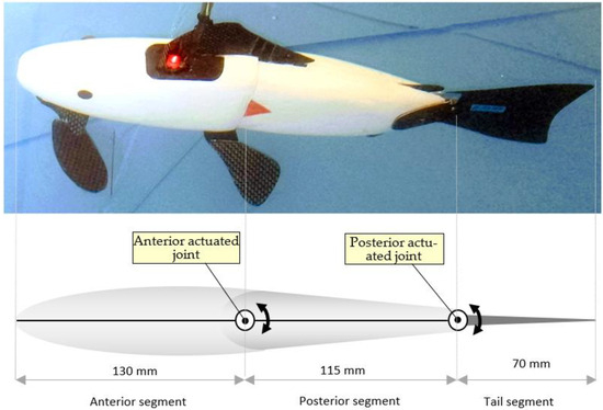
Figure 1.
Fishbot submerged in water (top) and its simplified overview (bottom).
The actuated joints are being undulated by servo motors. Each motor is governed by a sinusoidal control signal (generated by the controller—“central pattern generator”) that sets the instant angle of the actuated joint with a sampling interval of 20 ms. We consider the sinusoidal (harmonic) patterns of control signals because these patterns are a good approximation of the patterns observed in natural fishes [15]. Moreover, such harmonic oscillations result in low accelerations and low jerk of the angular movements of the joints, which favorably affect the wear-and-tear of the servo motors and the mechanical components of the bot.
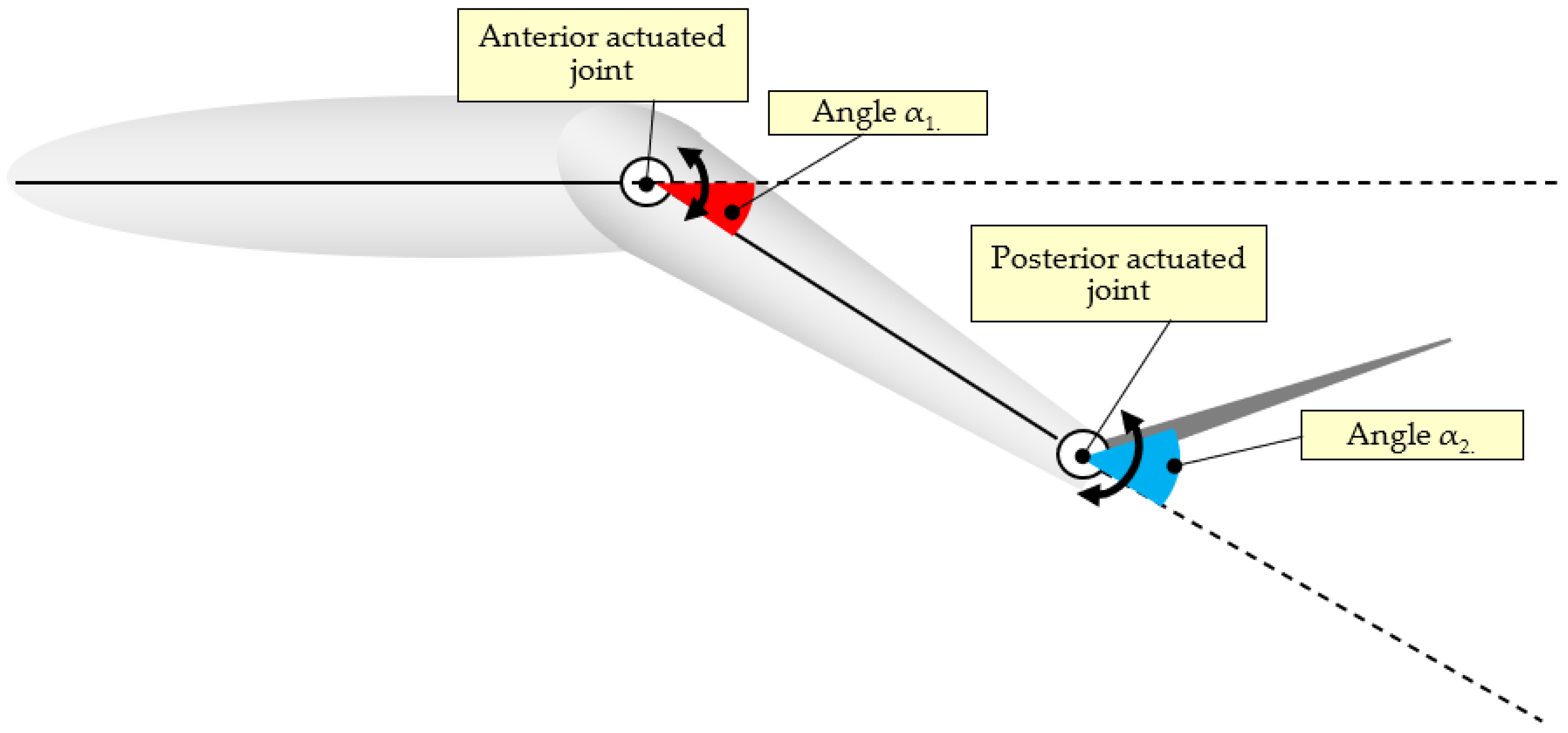
The anterior joint angle is denoted as the angle value α1 while the posterior one is denoted as α2 (Figure 2). Angles depending on the sinusoidal signal can be expressed using Equations (1) and (2), where f is the frequency of undulation, A1 is the angular amplitude of the anterior joint, A2 is the angular amplitude of the posterior joint, and β is the phase shift between the two signals α1 and α2.
α1(t) = A1 × sin(2 × π × f × t)
α2(t) = A2 × sin(2 × π × f × t + β)
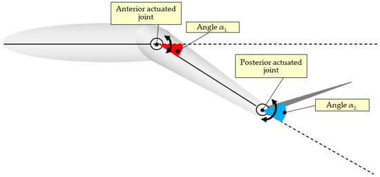
Figure 2.
Angles α1 and α2 of the fully actuated anterior and posterior joints of the fishbot.
In the previous work on the fully actuated fishbot, we used genetic algorithms to evolve the optimal values of the four parameters of undulation A1, A2, f, and β that result in the fastest speed of locomotion [3,13]. In the current research, we use the evolved optimal values of these parameters, as well as the resulting speed of locomotion (and associated energy efficiency) of the fully actuated robot for a comparative analysis of the experimental results.
2.2. Undulation Analysis
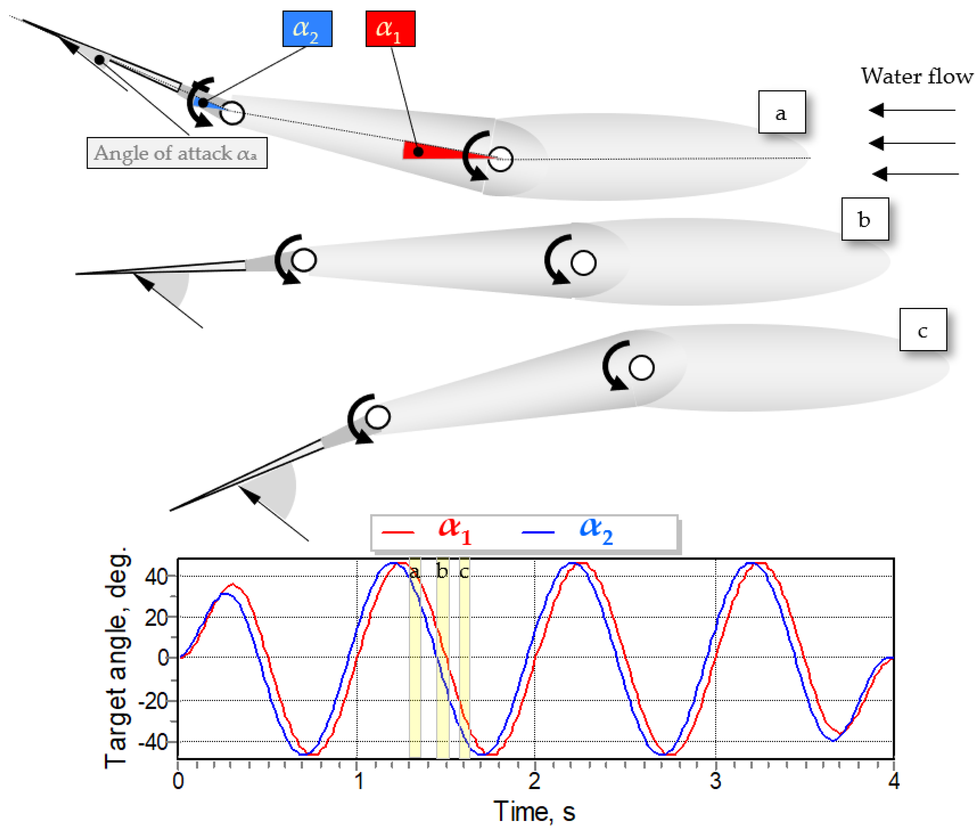
The swimming propulsion of the fishbot is produced by undulations that are provided by two actuated joints. As illustrated in Figure 3, a single undulation can be split into three different phases as follows [16]: beginning (Figure 3a), middle (Figure 3b), and ending (Figure 3c).

Figure 3.
Phases of undulation of fully actuated fishbot. α1, α2, and αa denote the angular deviation of the two joints and the angle of attack of the tail fin, respectively. Notice that the angle of attack is relatively small at the beginning of undulation and then gradually increases to values that are higher than the critical value (typically about 15°). Steps a, b and c represent different position of the fishbot body during a single phase of undulation.
According to the dynamic lift theory of fish locomotion, when the undulation begins (Figure 3a), the moving tail fin—due to the certain angle relative to the direction of the water flow (i.e., an angle of attack)—produces a lift (thrust) L by pushing the water in the same backward direction as the water flow [17]:
where CL is the coefficient of the lift of the fin, ρ is the density of the fluid (water), U is the velocity of the fin, and A is the planform area of the fin. For symmetrical hydrofoils, such as the tail fin of fishes, CL can be approximated as follows:
where αa is the angle of attack of the fluid.
L = CL(1/2) ρU2A
CL ≈ 2παa
However, the above Equation (4) holds only for small values (up to the critical value of about 15°) of αa. At values of αa that are higher than the critical one, a stall occurs, i.e., a separation of the turbulent flow behind the fin, resulting in an abrupt reduction in the lift and a significant increase in the hydrodynamic drag. From the second phase (Figure 3b,c), in which the fin moves in a blunt angle relative to the water flow, the tail fin stalls and would not be able to produce any thrust. Moreover, the tail fin moves in an opposite direction to the water flow (Figure 3c). This would result in a high-pressure build-up at the front part of the tail fin (i.e., “lower” part of the hydrofoil), and a low-pressure area behind the fin (the “upper” part of the hydrofoil). Such a pressure difference would result in turbulent fluid flow between the front and rear parts of the fin, resulting in flow separation and, ultimately, in hydrodynamic pressure (form) drag D that can be expressed as follows [17]:
where CD is the coefficient of drag, ρ is the density of the fluid (water), U is the velocity of the fin, and A is the planform area of the fin. The inflicted hydrodynamic drag would result in an undesired braking effect. The overall propulsion force would depend on the difference between the thrust and braking forces generated by the above-mentioned phases of undulation [18,19]. Consequently, enhancing the thrust or (and) diminishing the braking associated with these phases of undulation might result in a favorable overall increase in the propulsion thrust. We shall elaborate in the next subsection on how the proposed limited underactuation could achieve such an overall increase in the thrust.
D = CD(1/2) ρU2A
For simplicity, we assume that the water flow is both (i) laminar and (ii) in a direction parallel to the longitudinal axis of the anterior segment of the bot. In reality (e.g., due to the Coanda effect, vortices, etc.), this might not be exactly the case. Also, we consider the pressure drag only, ignoring the second component of the overall hydrodynamic drag—the skin friction drags. We assume that the value of the latter is negligible due to the streamlined body of the fishbot and the smooth surface of its fairings. Nevertheless, we assume that these simplifications do not significantly compromise the fidelity of the proposed approach.
2.3. The Concept of Limited Underactuation
Unlike actuated joints, underactuated joints do not use any actuators (servomotors). This kind of joint can be compared to a completely loose (free) joint that will move according to the environmental forces exerted on it. Our approach consists of implementing a new joint on the fishbot tail segment in order to reduce the hydrodynamic drag during the above-mentioned braking phase of undulation (Figure 3c). Also, because the underactuated joint is an environment-dependent one, its implementation may prevent the tail fin from being opposed to the direction of water flow. However, even if complete looseness might result in lower hydrodynamic drag during the braking phase of undulation (Figure 3c), it would also result in lower thrust in the initial phase of undulation (Figure 3a).
From this standpoint, we hypothesize that a joint with limited freeness may allow both (i) a reduction in drag during braking and (ii) the production of enough thrust during thrusting to possibly favorably shift the balance of these two phases, yielding an overall increase in the propulsion force. Therefore, we have designed a “limited underactuated” tail joint that is allowed to move freely but only within a limited angular range. The angular limiter defines the maximum angle of underactuation δ (Figure 4 and Figure 5) that could be achieved by the joint while moving depending on the environmental conditions. Moreover, the angle δ could be manually adjusted for the purpose of investigating its optimal value from the viewpoint of achieving a maximum speed or maximum energy efficiency of locomotion. However, it is fixed during undulation.
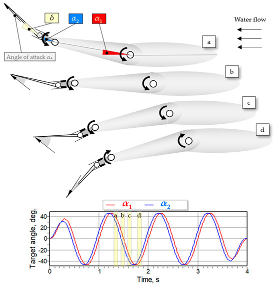
Figure 4.
Phases of undulation of fishbot featuring a limitedly underactuated posterior joint. α1, α2, αa, and δ denote the angular deviation of the two joints, the angle of attack of the tail fin, and the maximum angle of the limited underactuation, respectively. The phases of undulation feature reduced values of the angle of attack compared to the analogical phases of undulation of the fully actuated fishbot (Figure 3). Step d represent the gesture and position of the fishbot body when a new phase of undulation is starting.
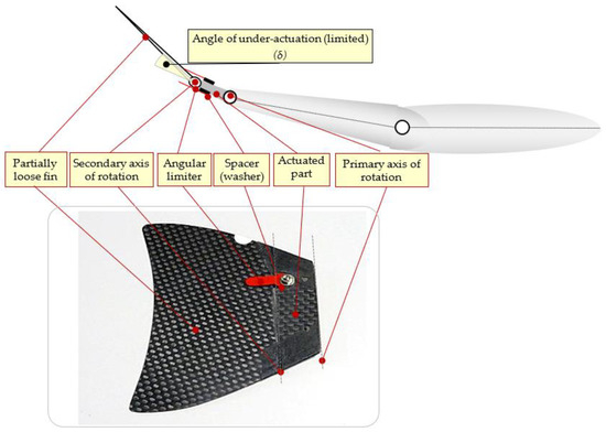
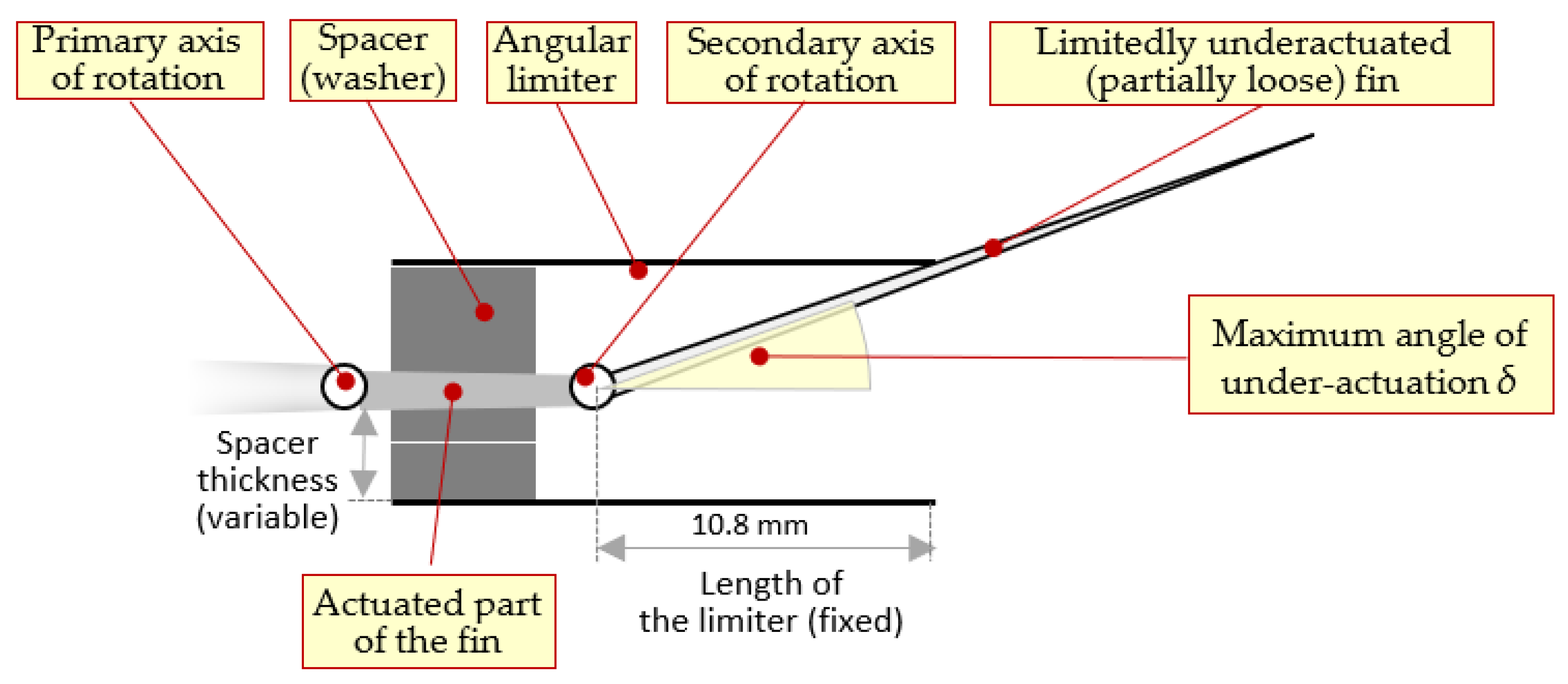
Figure 5.
Implementation of the limited underactuated tail fin of the fishbot.
We can compare the behavior of the tail fin featuring the proposed limited underactuated joint (Figure 4) with that of the canonical fully actuated one (Figure 3). The main concern that we intend to address is the unwanted hydrodynamic drag during the braking phase (Figure 3c and Figure 4c) caused by the stall of the fin due to the higher angles of attack of the latter. Regarding the expected behavior of a single undulation with a limited underactuated joint (Figure 4c), the braking phase is associated with an orientation of the tail fin mainly along the water flow (and, consequently, with an overall reduction in the angle of attack), which we expect to result in a reduction in the hydrodynamic pressure drag. As undulation has the same period for both analyses, we can conclude that the lower angle of attack would result in both (i) a delayed (during the thrust phase of the undulation as illustrated in Figure 4a,b) and (ii) shorter and less severe (during the braking phase, as shown in Figure 4c) stall of the tail fin. However, because, compared to the fully actuated joint, the reduced angle of attack due to the limited underactuation—according to Equation (4)—might also reduce the effectiveness of the thrusting phase of undulation (Figure 3a and Figure 4a), we are unsure about whether (depending on the angle of underactuation δ) the limited actuation would result in increased net propulsion.
2.4. Implementation of the Limited Underactuated Joint
We decided to split the tail fin into two parts. The first one is a solid part that is linked to the fish body via a fully actuated joint (Figure 5). This joint rotates around the primary axis of rotation, as undulated by the rear servo motor. The second joint is implemented to join the solid tail fin part with the partially loose part of the fin. The partially loose fin will be loose within the angles of rotations defined by the angular limit δ and would rotate as a fully actuated joint when the angle of rotation reaches δ. The second axis on which the limited underactuated joint would have an impact will be called the secondary axis of rotation. The area of the underactuated part of the tail fin is significantly larger than that of the fully actuated one.
The adjusting of the maximum angle of underactuation δ is accomplished by changeable spacers (washers, featuring different thicknesses) under the screw that attaches the angular limiter to the fully actuated part of the fin, as illustrated in Figure 5 and Figure 6. Knowing the thickness of the spacers and the length of the limiter, we can calculate the maximum angle of underactuation δ as follows:
where, in our implementation, the length of the limiter is 10.8 mm and the spacer thickness varies and could be set to 0.4 mm, 0.8 mm, 1.2 mm, 1.6 mm, and 2.0 mm, resulting in the maximum angle of underactuation δ of 2.1°, 4.2°, 6.3°, 8.4°, and 10.5°, respectively.
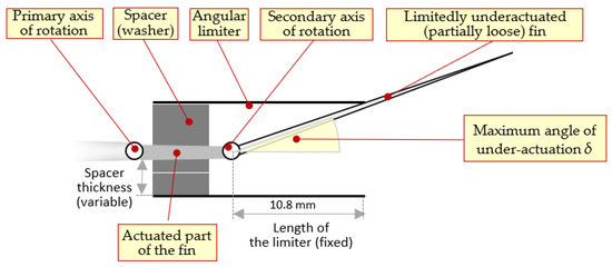
Figure 6.
Implementation of angular limiter of the limited underactuated joint of the tail fin.
The kinematic diagram of the fishbot with a limited underactuated joint of the tail fin is shown in Figure 7.

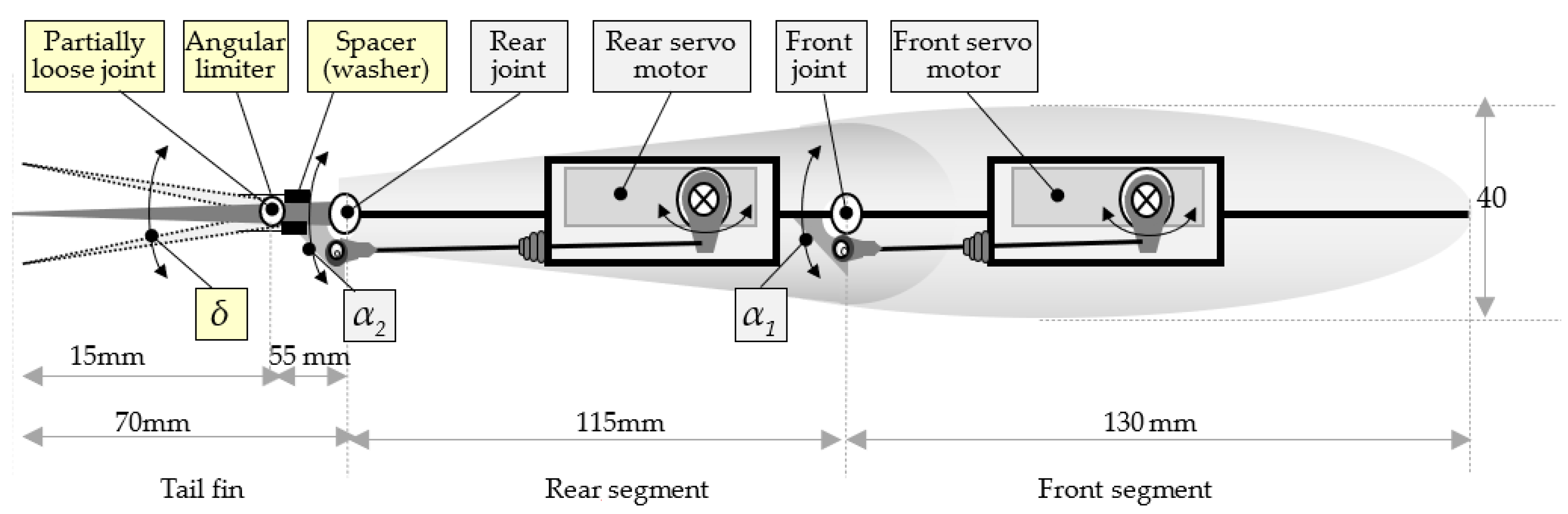
Figure 7.
Kinematic diagram of the fishbot with a limited underactuated joint of the tail fin.
3. Experimental Results
3.1. Experimental Setup
To investigate the effect of the underactuated tail on both the speed of locomotion and energy efficiency of the fishbot, we conducted experiments with different degrees of underactuation, i.e., with different values of the maximum angle of underactuation δ. The experimental process with the setup value of the maximum angle of underactuation consists of running four runs (to account for the effect of environmental noise) of the fish robot with a different frequency (parameter f in Equations (1) and (2)) at the maximum amplitude of undulation of both servo motors (i.e., parameters A1 and A2 in Equations (1) and (2) are set to 45°) and no phase shift between the undulations of both servo motors (i.e., the parameter β in Equation (2) is set to 0). We have verified in our previous research that these values of amplitudes and the phase shift do indeed result in the maximum speed and energy efficiency of the robot [3,12,13]. We have tested five different frequencies ranging from 0.4 Hz to 2.0 Hz with a discretization step of 0.4 Hz. The maximum frequency of oscillation is set to a value that is close to but does not exceed the technical specification of the maximum angular speed (600°/s) of the servo motors. The maximum angular velocity ωMAX that servo motors sustain during the undulation could be obtained from the maximum value of the derivative of the turning angles of undulation, as expressed in Equations (1) and (2):
ωmax = 2 × π × f × A
For f = 2.0 Hz and A = 45°, we obtain ωmax = 565°/s, which is well within the technical specification of the servo motors, with a safety margin (to 600°/s) of about 6%.
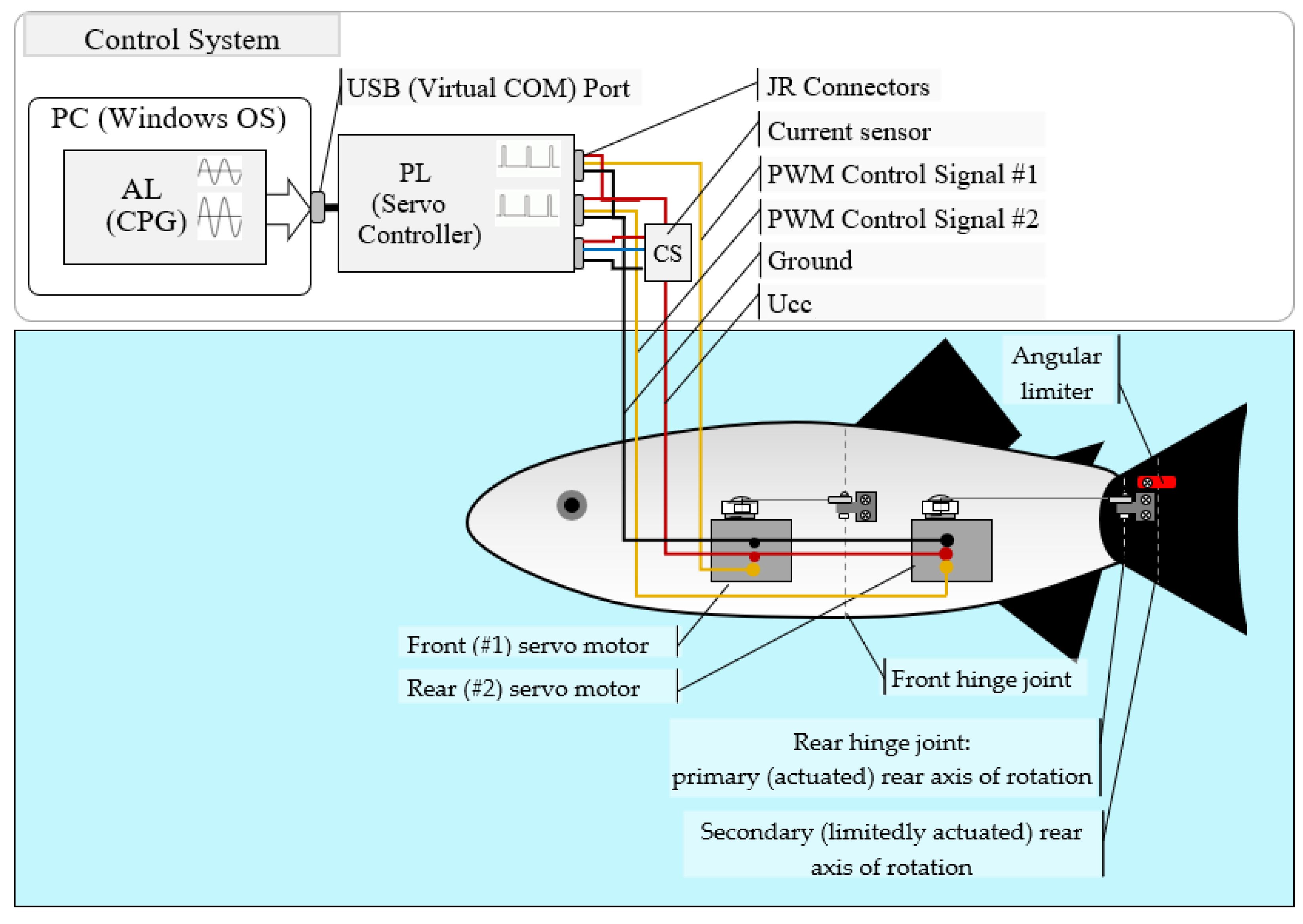
The results of the four runs are aggregated based on the calculated mean of the achieved performances (e.g., speed and energy efficiency). The experimental system comprises the (i) fishbot (ii) and its control system, as illustrated in Figure 8.
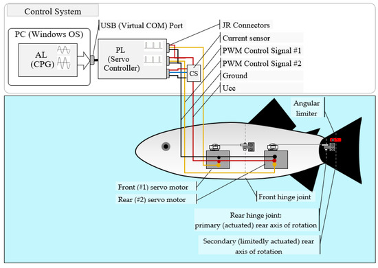
Figure 8.
Fishbot and its control system. The abbreviations AL, PL, CPG, CS, and PWM denote the abstract layer, physical layer, central pattern generator, current sensor, and pulse-width modulation, respectively.
The control system consists of an abstract layer (AL) that generates the control signals with a sampling interval of 20 ms according to Equations (1) and (2), and a physical layer (PL) that converts the instant values of the turning angles of the servo motors to pulse-width-modulated (PWM) signals that govern the instant angular positions of the motors. Also, we connected a current sensor (CS) serially to the power supply (Ucc = 5 V) line of the robot in order to estimate the electrical power consumption of the robot during the trials. For hardware implementation of the PL and CS, we used Micro Maestro 6-Channel USB Servo Controller and ACS724 (both produced by Pololu Robotics and Electronics), respectively [20,21].
In addition to the fishbot and its control system, the experimental setup also involves an optical tracker, which uses a video feed from an overhead camera to track the fishbot (via a bright red LED mounted on the latter) and estimate the instant speed (as the Euclidean distance between the consecutive positions of the robot, divided into precisely measured time intervals between these positions) of the robot during the 5 s trial. The maximum value of the instant speed is assumed to be the actual steady-state swimming speed of the fishbot. The details of the experimental setup are elaborated in [3].
3.2. Maximum Speed of Locomotion
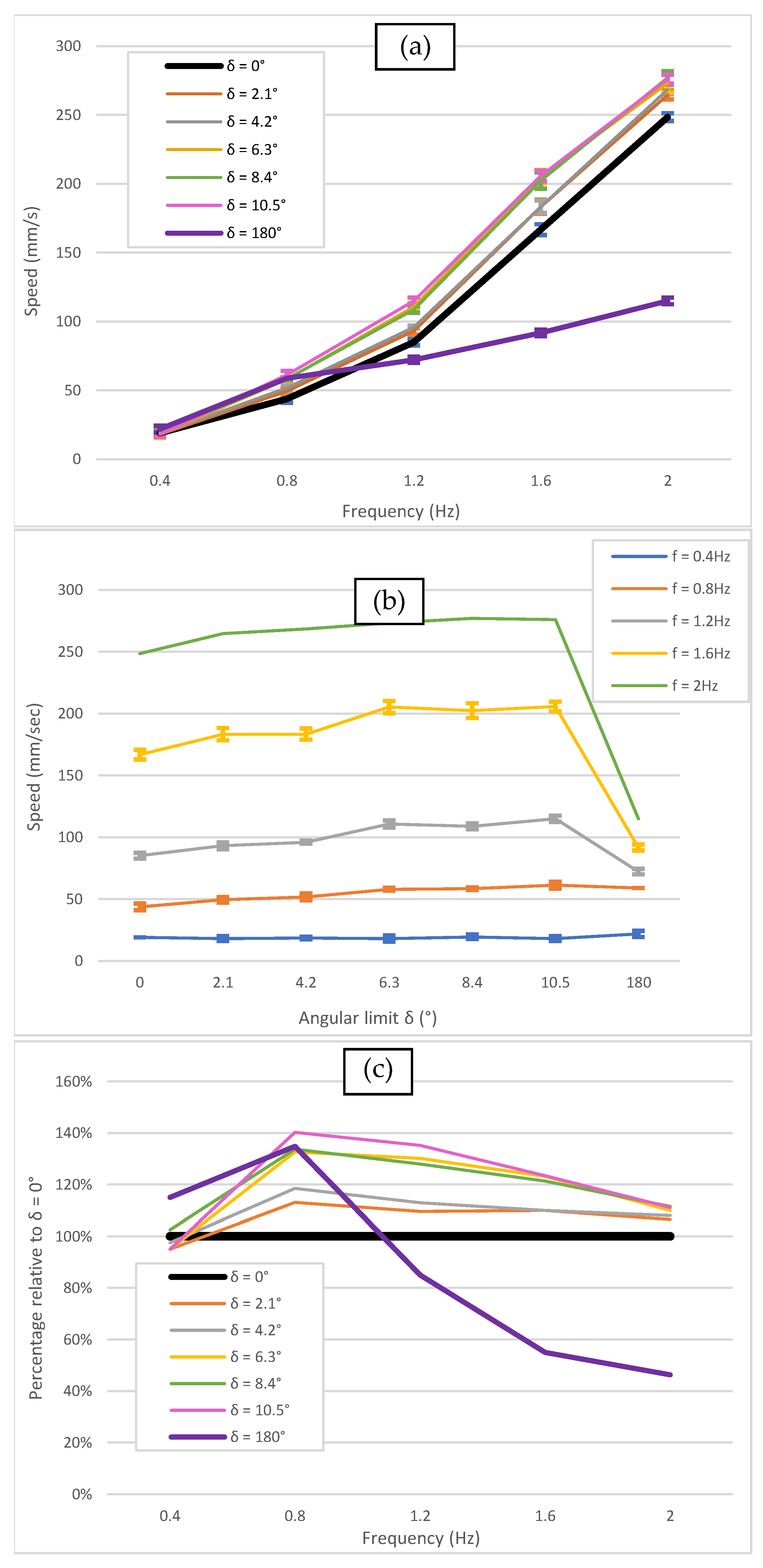
Figure 9 depicts the speed of locomotion as a function of the frequency of oscillations f and angular limit of underactuation δ. As illustrated in Figure 8 and Figure 9c, for the maximum angles of underactuation δ equal to 2.1°, 4.2°, 6.3°, 8.4°, and 10.5° (corresponding to using one, two, three, four, and five washers, each 0.4 mm thick), the maximum speed is higher than that of the fully actuated joint (i.e., δ = 0). This observation confirms the hypothesis that the limited underactuation might have a favorable effect on the speed of the robot. We assume that the achieved reduction in the hydrodynamic drag during the braking phase of undulation (Figure 4c) overcompensates for the expected reduction in effectiveness of the thrusting phase of undulation (Figure 4a). Moreover, we can notice that the higher frequency of oscillation results in a higher maximum speed regardless of the maximum angle of limited underactuation (Figure 9b). Compared to the fully actuated joint, the maximum speedup of limited underactuation is achieved for a relatively low frequency of oscillation—around 0.8 Hz—as illustrated in Figure 9c. The maximum speedup of 1.4 times is achieved for the maximum angle of limited underactuation δ = 10.5°.
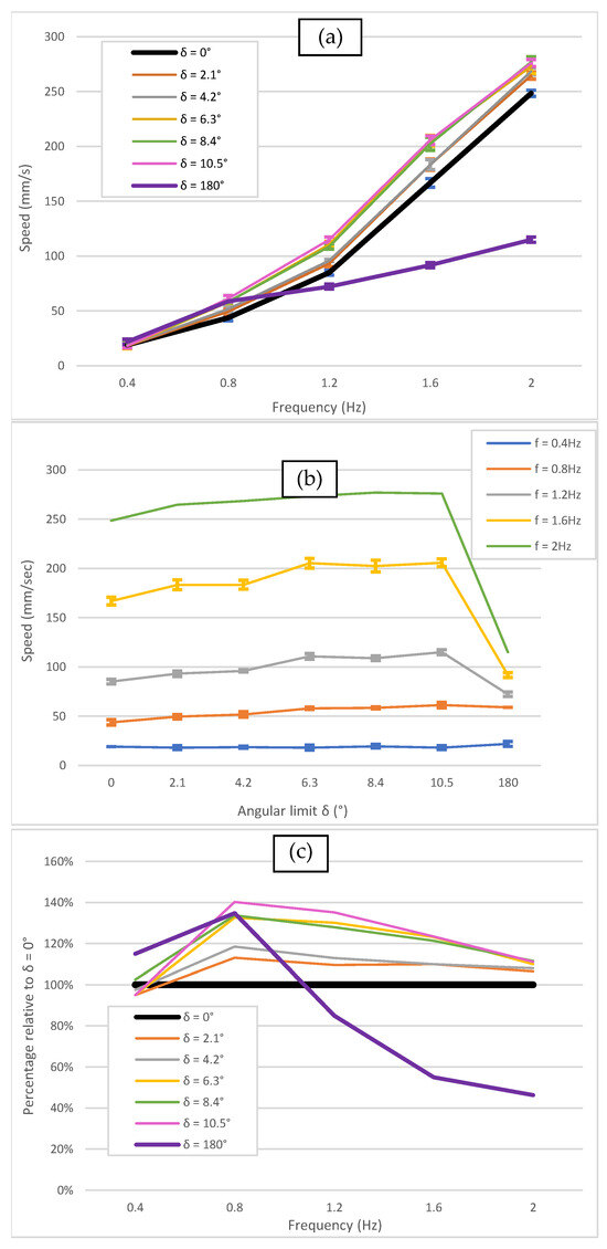
Figure 9.
Maximum speed of the fishbot during the trial as a function of the frequency of oscillations f (a) and maximum angle of the limited underactuation δ (b), and in relation to the speed of the robot featuring a fully actuated (δ = 0°) joint of the tail fin (c).
Also, as Figure 9c illustrates, the fully underactuated joint (δ = 180°) is somehow superior to the fully actuated one (δ = 0°) for lower frequencies of oscillations (up to 1.2 Hz). However, as the frequency increases, the speed of the robot featuring a fully underactuated joint deteriorates rapidly and becomes inferior to both fully underactuated and limited underactuated robots.
As the frequency of oscillation increases, the limited underactuation also has a favorable effect on the maximum speed of the robot. As depicted in Figure 9c, however, this effect is not as profound as the one observed at the lower frequencies of oscillation.
3.3. Energy Efficiency of Locomotion
As a second metric, the energy efficiency EE corresponds to the distance D that the fishbot can swim autonomously with a given energy (e.g., stored in its batteries) EB:
EE = D/EB
Equation (8) can be rewritten as
and
where T, V, IAVR, and Ucc in Equation (9) denote the time that the robot would eventually travel before it completely exhausts the available energy, swimming speed (obtained from the optical tracker, as elaborated in the previous Section 3.2), average electrical current consumed by the robot during the trial (obtained from the current sensor connected serially to the power supply line of the robot, as illustrated in Figure 8), and constant power supply voltage (5 V), respectively. In our experiments, we obtained the energy efficiency according to Equation (10) as the ratio of the speed of locomotion to the electrical power consumed by the robot during the trial.
EE = (V × T)/(IAVR × UCC × T)
EE = V/(IAVR × UCC)
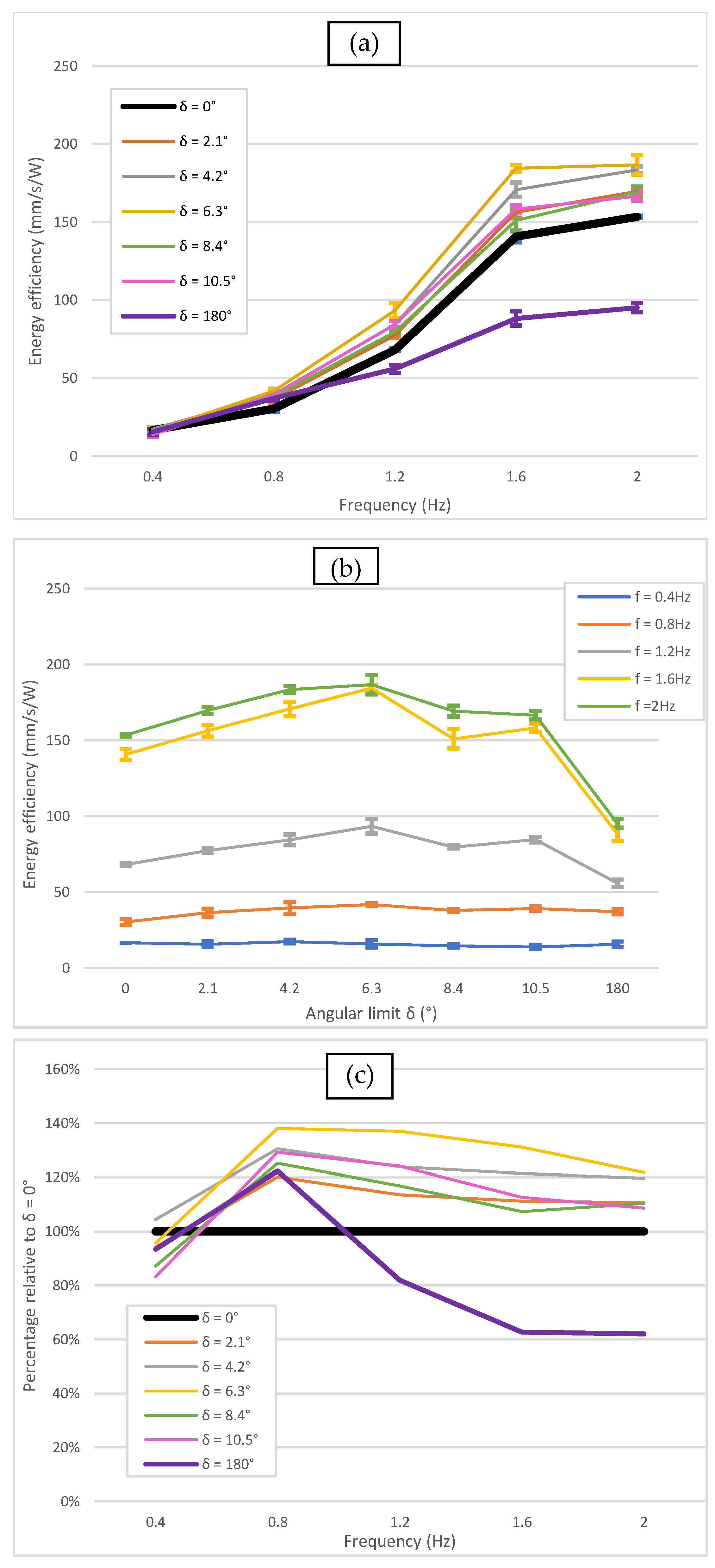
As shown in Figure 10, similar to the results obtained for the maximum speed of locomotion, compared to the fully actuated robot, the limited underactuation results in improved energy efficiency. As Figure 10c depicts, compared to the fully actuated robot, a maximum increase in energy efficiency of about 1.37 times is achieved for the maximum angle of underactuation δ = 6.3° at a frequency of oscillation of 0.8 Hz. For the whole range of tested frequencies, however, and for all tested values of the maximum angle of underactuation δ, the fishbot featuring a limited underactuated fin is superior (in terms of its energy efficiency) to that with the fully actuated joint (Figure 10a,b).
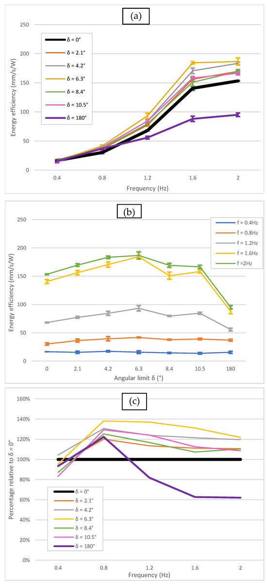
Figure 10.
Energy efficiency of the fishbot as a function of the frequency of oscillations f (a) and maximum angle of the limited underactuation δ (b), and in relation to the speed of the robot featuring a fully actuated (δ = 0°) joint of the tail fin (c).
Analogous to the results obtained for the maximum speed of the robot, as Figure 10c illustrates, the fully underactuated joint (δ = 180°) is somehow superior to the fully actuated one (δ = 0°) for lower frequencies of oscillations (up to 1 Hz). As the frequency increases, however, the energy efficiency of the robot featuring a fully underactuated joint deteriorates sharply and becomes inferior to both fully underactuated and limited underactuated robots.
4. Discussion
Compared to both fully actuated and fully underactuated, the limited underactuated tail joint yields a favorable performance (e.g., speed and energy efficiency of locomotion) of the fishbot. However, the effect of the limited underactuated joint is profound at lower frequencies of oscillations and tends to somehow diminish as the frequency increases. In order not to exceed the technical specifications of the angular speed of servo motors (600°/s, as detailed in Section 3.1), we could not experiment with higher frequencies of oscillations. However, from the data visualized in Figure 9 and Figure 10, we may suppose that there is a threshold frequency at which the limited underactuated tail joint will no longer be performant regardless of the angle of the underactuation.
Within the whole range of frequencies, the behavior of the performance increases with the increase in the maximum angle of underactuation δ for values of up to 10.5°. However, for δ = 180° (fully underactuated joint), the performance decreases sharply, suggesting that, beyond the advantage of providing naturally plausible undulatory gaits of the fishbot, underactuation might not necessarily result in a better speed and (or) energy efficiency of the robot. We could conclude that a limited underactuated joint is superior to both fully actuated and fully underactuated ones in terms of the speed and energy efficiency of locomotion.
As Figure 8 suggests, the optimal angle of underactuation that results in maximum speed is different depending on the frequency of undulation. At higher frequencies, a lower angle of limited underactuation should be used to reach optimal performance. This phenomenon could be the result of complex forces applied to the limited underactuation joint. Consequently, the optimal performance of the fish robot should be represented as a function of both the frequency of undulation f and the maximum angle of limited underactuation δ.
And, finally, it should be noted that the optimal angle of underactuation that results in the maximum speed is different from that of the maximum energy efficiency (δ = 10.5° and δ = 6.3°, respectively). The drawback of the proposed implementation of the limited underactuation via an angular limiter implies that it could not be adjusted in real time. This might suggest the feasibility of considering in the future a different implementation of the angular limiter that would allow the robot to adjust the degree of underactuation “on the fly” depending on the task (maximum speed or maximum energy efficiency) that it is currently facing.
5. Conclusions
In our research, we intended to explore the possibility of optimizing the performance (e.g., speed and energy efficiency) of the fishbot by enhancing its morphology (rather than control) and, specifically, by adopting a limited underactuated posterior (tail) joint as a special case of underactuation. The experimental results suggest that, compared to the fully actuated and fully underactuated fishbot, the robot featuring a limited underactuated joint has a superior performance. In our future research, we are planning to consider an implementation of the angular limiter of underactuation that allows for an adjustment in real time.
Author Contributions
Project administration, conceptualization, methodology, software, and resources: I.T.; Investigation: Y.H.; Validation: Y.H., I.T. and T.K.; Interpretation of results: Y.H., I.T. and T.K.; Visualization: Y.H. and I.T.; Writing: original draft preparation: Y.H.; Writing: review and editing: Y.H., I.T. and T.K.; Supervision: I.T. and T.K. All authors have read and agreed to the published version of the manuscript.
Funding
This research received no external funding.
Institutional Review Board Statement
Not applicable.
Informed Consent Statement
Not applicable.
Data Availability Statement
Data available upon a request (to Y.H.).
Conflicts of Interest
The authors declare no conflict of interest.
References
- Fish, F. Swimming Strategies for Energy Economy. In Fish Locomotion. An Eco-Ethological Perspective; CRC Press: Boca Raton, FL, USA, 2010. [Google Scholar] [CrossRef]
- Babu Mannam, N.P.; Alam, M.M.; Krishnankutty, P. Review of biomimetic flexible flapping foil propulsion systems on different planetary bodies. Results Eng. 2020, 8, 100183. [Google Scholar] [CrossRef]
- Tanev, I. Fish Robot: Design, Control and Evolution of Undulatory Swimming Gaits. Technical Report. July 2021. 33p. Available online: http://isd-si.doshisha.ac.jp/itanev/TR/TR_20210716_Fishbot.pdf (accessed on 2 October 2023).
- Vo, T.Q.; Kim, H.S.; Lee, B.R. Smooth gait optimization of a fish robot using the genetic-hill climbing algorithm. Robotica 2012, 30, 257–278. [Google Scholar] [CrossRef]
- Roper, D. Energy Based Control System Designs for Underactuated Robot Fish Propulsion. Ph.D. Thesis, University of Plymouth, Plymouth, UK, 2013. [Google Scholar] [CrossRef]
- Wang, W.; Guo, J.; Wang, Z.; Xie, G. Neural controller for swimming modes and gait transition on an ostraciiform fish robot. In Proceedings of the 2013 IEEE/ASME International Conference on Advanced Intelligent Mechatronics, Wollongong, NSW, Australia, 9–12 July 2013; IEEE: Piscataway, NJ, USA, 2013; pp. 1564–1569. [Google Scholar] [CrossRef]
- Wang, W.; Gu, D.; Xie, G. Autonomous Optimization of Swimming Gait in a Fish Robot With Multiple Onboard Sensors. IEEE Trans. Syst. Man Cybern. Syst. 2019, 49, 891–903. [Google Scholar] [CrossRef]
- Zhu, J.; White, C.; Wainwright, D.K.; Di Santo, V.; Lauder, G.V.; Bart-Smith, H. Tuna robotics: A high-frequency experimental platform exploring the performance space of swimming fishes. Sci. Robot. 2019, 4, eaax4615. [Google Scholar] [CrossRef]
- Iida, F.; Pfeifer, R.; Seyfarth, A. AI in Locomotion: Challenges and Perspectives of Underactuated Robots. In 50 Years of Artificial Intelligence: Essays Dedicated to the 50th Anniversary of Artificial Intelligence; Lungarella, M., Iida, F., Bongard, J., Pfeifer, R., Eds.; Lecture Notes in Computer Science; Springer: Berlin/Heidelberg, Germany, 2007; pp. 134–143. [Google Scholar] [CrossRef]
- Romano, D.; Wahi, A.; Miraglia, M.; Stefanini, C. Development of a Novel Underactuated Robotic Fish with Magnetic Transmission System. Machines 2022, 10, 755. [Google Scholar] [CrossRef]
- Takada, Y.; Nakanishi, Y.; Araki, R.; Nonogaki, M.; Wakisaka, T. Effect of Material and Thickness about Tail Fins on Propulsive Performance of a Small Fish Robot. J. Aero Aqua Bio-Mech. 2010, 1, 51–56. [Google Scholar] [CrossRef]
- Sancho, M.A.; Tanev, I.; Shimohara, K. Fitness Lookup Table Reduces the Runtime of Evolution of Swimming Gaits of Fish Robot. In Proceedings of the 28th Symposium on Artificial Life and Robotics (AROB-ISBC-SWARM 2023), Beppu, Japan, 25–27 January 2023; p. 6. [Google Scholar]
- Komoto, T.; Tanev, I.; Shimohara, K. Evolving the Thrust of Undulatory Swimming Gaits of Fish Robot. In Proceedings of the 27th Symposium on Artificial Life and Robotics (AROB-ISBC-SWARM 2022), Beppu, Japan, 25–27 January 2022; p. 6. [Google Scholar]
- Quinn, D. To Swim like a Tuna, Robotic Fish Need to Change How Stiff Their Tails Are in Real Time. The Conversation. Available online: http://theconversation.com/to-swim-like-a-tuna-robotic-fish-need-to-change-how-stiff-their-tails-are-in-real-time-168046 (accessed on 8 February 2024).
- Čech, M.; Jarolím, O.; Kubecka, J.; Vašek, M.; Peterka, J.; Matěna, J. Sinusoidal Swimming in Fishes: Using Hydroacoustics, Underwater Camera and Direct Sampling Techniques to Understand Peculiar Fish Behavior. October 2010. Available online: https://www.researchgate.net/profile/Martin-Cech-3/publication/337244260_Sinusoidal_swimming_in_fishes_using_hydroacoustics_underwater_camera_and_direct_sampling_techniques_to_understand_peculiar_fish_behavior/links/5dcd22fe299bf1b74b3f6c0f/Sinusoidal-swimming-in-fishes-using-hydroacoustics-underwater-camera-and-direct-sampling-techniques-to-understand-peculiar-fish-behavior.pdf (accessed on 16 May 2024). [CrossRef]
- Bale, R.; Shirgaonkar, A.A.; Neveln, I.D.; Bhalla, A.P.; MacIver, M.A.; Patankar, N.A. Separability of Drag and Thrust in Undulatory Animals and Machines. Sci. Rep. 2014, 4, 7329. [Google Scholar] [CrossRef] [PubMed]
- Arakeri, J.H. Fluid Mechanics of Fish Swimming: Lift-based Propulsion. Resonance 2009, 14, 32–46. Available online: https://www.ias.ac.in/article/fulltext/reso/014/01/0032-0046 (accessed on 16 May 2024). [CrossRef]
- MacDonald, J. What Makes Fish Swim Fast. JSTOR: Digit. Libr. Sch. Res. Stud. 2017. Available online: https://daily.jstor.org/what-makes-fish-swim-fast/ (accessed on 16 May 2024).
- Webb, P.W. Simple Physical Principles and Vertebrate Aquatic Locomotion. Am. Zool. 1988, 28, 709–725. [Google Scholar] [CrossRef]
- Pololu Robotics and Electronics. Micro Maestro 6-Channel USB Servo Controller. Available online: https://www.pololu.com/product/1350 (accessed on 16 May 2024).
- Pololu Robotics and Electronics. ACS724LLCTR-2P5AB Current Sensor Carrier. Available online: https://www.pololu.com/product/4040 (accessed on 16 May 2024).


Disclaimer/Publisher’s Note: The statements, opinions and data contained in all publications are solely those of the individual author(s) and contributor(s) and not of MDPI and/or the editor(s). MDPI and/or the editor(s) disclaim responsibility for any injury to people or property resulting from any ideas, methods, instructions or products referred to in the content. |
© 2024 by the authors. Licensee MDPI, Basel, Switzerland. This article is an open access article distributed under the terms and conditions of the Creative Commons Attribution (CC BY) license (https://creativecommons.org/licenses/by/4.0/).