Article

Linear Contact Load Law of an Elastic–Perfectly Plastic Half-Space vs. Sphere under Low Velocity Impact

1
School of Physics, Nanjing University of Science and Technology, Nanjing 210094, China
2
School of Physical and Mathematical Sciences, Nanjing Tech University, Nanjing 210094, China
*
Author to whom correspondence should be addressed.
Appl. Sci. 2024, 14(12), 5018; https://doi.org/10.3390/app14125018
Submission received: 11 May 2024 / Revised: 1 June 2024 / Accepted: 4 June 2024 / Published: 8 June 2024
(This article belongs to the Section Mechanical Engineering)

Abstract

:
The impact of contact between two elastic–plastic bodies is highly complex, with no established theoretical contact model currently available. This study investigates the problem of an elastic–plastic sphere impacting an elastic–plastic half-space at low speed and low energy using the finite element method (FEM). Existing linear contact loading laws exhibit significant discrepancies as they fail to consider the impact of elasticity and yield strength on the elastic–plastic sphere. To address this limitation, a novel linear contact loading law is proposed in this research, which utilizes the concept of equivalent contact stiffness rather than the conventional linear contact stiffness. The theoretical expressions of this new linear contact loading law are derived through FEM simulations of 150 sphere and half-space impact cases. The segmental linear characteristics of the equivalent contact stiffness are identified and fitted to establish the segmental expressions of the equivalent contact stiffness. The new linear contact loading law is dependent on various factors, including the yield strain of the half-space, the ratio of elastic moduli between the half-space and sphere, and the ratio of yield strengths between the half-space and sphere. The accuracy of the proposed linear contact loading law is validated through extensive Finite Element Method simulations, which involve an elastic–plastic half-space being struck by elastic–plastic spheres with varying impact energies, sizes, and material combinations.

1. Introduction

Elastoplastic contact is a universal contact behavior, it occurs even at low impact velocity or low loading levels [1,2]. For example, impacts of the carbon steel hull shell of ships with icebergs [3], impacts of solar sail panels with space debris [4], impact damage to aircraft engine fan blades made of carbon-fiber-reinforced composites by birds [5] and the resultant peak impact force and kinetic energy loss [6], and car crashes [7]. Elastoplastic contact impact directly affects the bearing capacity and safety reliability of the structure [8,9,10], which is an important topic in engineering analysis. Because the contact plasticity occurs at a very small indentation, the elastoplastic contact induces high stress concentrating near the contact region with a small dimension. The contact deformation is extremely complicated and consequently makes the analysis solution of elastoplastic contact most often impossible.
Due to the complication of contact behavior, contact force and indentation are the two most important parameters in the contact process. Thus, many scholars have developed a force–indentation relationship (theoretical contact laws) for the elastoplastic contact problem [11,12,13,14]. Stronge [15] derived the contact force–indentation relation for the loading and unloading phases on the basis of a spherical–shell extension model [2] applied to the rod [16] and beam [17] impacts. Du and Wang [18] presented an elastic–plastic contact law to solve the coefficients of recovery for sphere–plate elastic–plastic impacts [19]. Thornton [20] proposed a simplified elastic–plastic contact law to compute the coefficient of recovery of a particle impact with a vessel wall. The existing theoretical contact laws are mainly provided for the quasi-static impacts of rigid spheres against elastic–plastic bodies. According to different selection methods of σ Y , which is the yield strength of the softer material [21,22,23], the contact type can be divided into three types: the indention type when σ Y s > σ Y b , the flattening type when σ Y s < σ Y b , and the combined type when σ Y s = σ Y b . For an elastic–plastic material indented by a rigid sphere or an elastic–plastic sphere pressed by a rigid flat, the Hertz contact law [24] can be adopted before the inception of plastic yielding, and the pressure is assumed to have an elliptic distribution. Many theoretical loading and unloading laws exist for indentation contact [2,25,26] and flattening contact [27,28,29]. However, the contact between two elastic–plastic bodies is more complex, and, until now, most studies of elastic–plastic contact behaviors have focused on the elastic–plastic materials contacted by a rigid sphere or a rigid flat, and the force–indentation relationship laws in combined contact types are scarce [30,31]. To consider the deformations of the contact between two elastic–plastic bodies, Ghaednia et al. [31] tried to adopt the yield stress ratio of the two contacting bodies as a controlling parameter. They proposed a complicated theoretical contact law that has not been sufficiently examined.
Furthermore, Taljat et al. [32,33] found that the compliance of the indenter cannot be neglected even though the ratio of elastic moduli between the indenter and indented material is at least three times. In experiments performed by Knapp et al. [34], it was found that, by using even extremely stiff material with the compressive yield stress of 3690 MPa, the compressive yield stress decreased by about 39% compared to that of the rigid indenter. To account for the elastic deformation of the indenter, Dong et al. [25] presented an implicit indentation model, and Ghaednia et al. [35] and Weng [36] presented an explicit loading law. However, a highly applicable method that can consider the indenter elastic–plastic deformation is still lacking.
The present study performs the systematic FE simulations for sphere–half space elastic–plastic impact at low speed, and a new linear contact law is proposed for the deformation characteristics. Section 2 introduces the linear contact law and finite element model. In Section 3, the influence of elastic–plastic contact deformation of the spherical indenter is considered. In Section 4, a new linear contact law is presented. Finally, the conclusions are presented in Section 5.

2. Linear Contact Law and Finite Element Model

2.1. Linear Contact Law

The impact contact process includes three stages: elastic loading, elastoplastic loading, and elastic unloading. The linear contact loading law [37] ignores the initial elastic loading stage and linearizes the elastic–plastic loading stage. The relationship between the impact contact force F and indentation δ [37] is as follows:
F = K h δ ,
where K h is the linear contact stiffness, and the slope of the loading curve is as follows:
K h = 2 π R p 0 ,
R is the radius of the sphere and p 0 is the average pressure under completely plastic conditions. For metal materials the following is true:
p 0 = 2.8 σ Y h ,
σ Y h is the yield strength of the object being hit. The linear contact loading law only considers the diameter of the impact sphere and the yield strength of the object being hit.

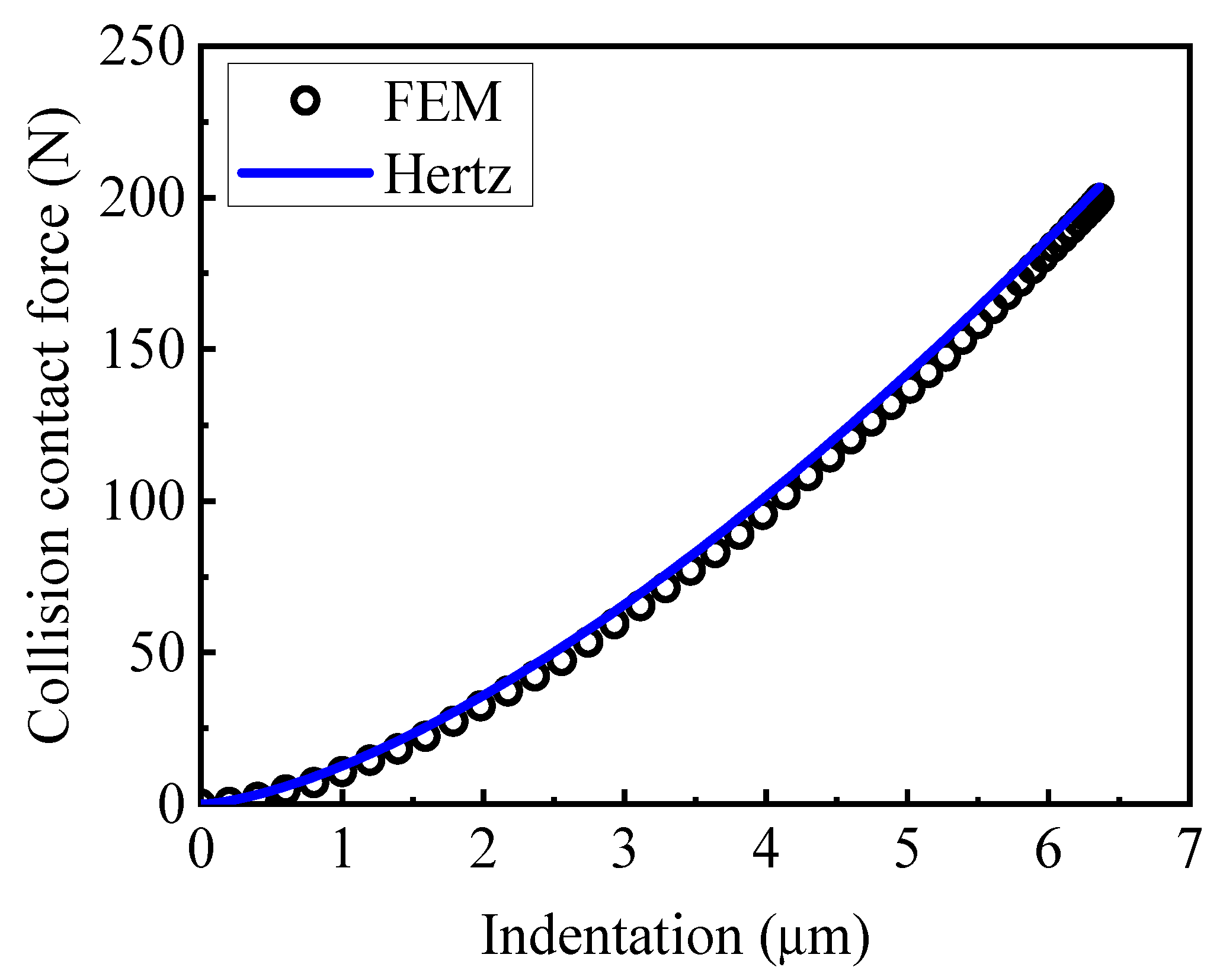
2.2. Finite Element Model

For an in-depth exploration of the low-velocity impact problems between an elastic–plastic sphere and an elastic–plastic half-space, the LS-DYNA program conducts numerical simulations to analyze the response of the elastic–plastic half-space to a center impact from the elastic–plastic sphere. The half-space is an isotropic material with radius r , height h , elastic modulus E h , yield limit σ Y h , and Poisson’s ratio υ h . The mass of the sphere is m s , modulus of elasticity is E s , yield strength σ Y s , and Poisson’s ratio is υ s . The dimensions and material properties of the sphere and the half-space are listed in Table 1. The initial impact velocity of the sphere is 1 m/s.
A 2D axisymmetric finite element model, as depicted in Figure 1, is developed for the analysis according to the axisymmetric nature. For the contact region, a regular dense mesh is divided. The number of meshes in the contact area in this model is 80 elements. In the outer region away from the contact area, in order to avoid the sudden change of mesh size, a regular mesh with gradually increasing size from fine to coarse is divided. According to the convergence test, the element contact penalty stiffness and tolerance are set to be 1 and 0.1, respectively, and the contact area needs to be guaranteed to be more than 40 elements discrete. Both the sphere and the half-space use PLANE 162 axisymmetric elements. The sphere comprises 7600 elements with 7811 nodes, while the half-space consists of 6800 elements with 7001 nodes. To simulate the half-space constraints, full displacement constraints are applied to the bottom edge mesh nodes of the half-space. According to the convergence test, both the height and radius of the half-space are selected to be larger than 20 R . The impact initial velocity is set for all nodes of the sphere. The contact between the sphere and the half-space is chosen as surface-to-surface contact without considering the friction between the contact surfaces. It is assumed that both the half-space and the sphere are perfectly elastic–plastic bodies and the Mises yield criterion determines the plastic yield. Due to the short impact time and the high acceleration produced by impacts, the explicit analysis strategy for general transient analysis is employed in the present study of low impacts. The forces resulting from gravity and damping remain negligibly small and are not considered in the finite element model.
In order to verify the accuracy of the finite element model, the impact force–indentation curve for an elastic impact is simulated in Figure 2 and compared with the Hertz theoretical solution [27]. The Hertz contact law is as follows:
F = 4 3 E * R * δ 1.5 ,
where E * is the equivalent contact modulus, 1 / E * = 1 / E h + 1 / E s , and R * is the effective radius equal to the sphere radius for sphere-half-space impacts. The validation results show that the finite element simulation results are consistent with the Hertz solution. The maximum impact force and maximum indentation errors are 1.9% and 2%, respectively.

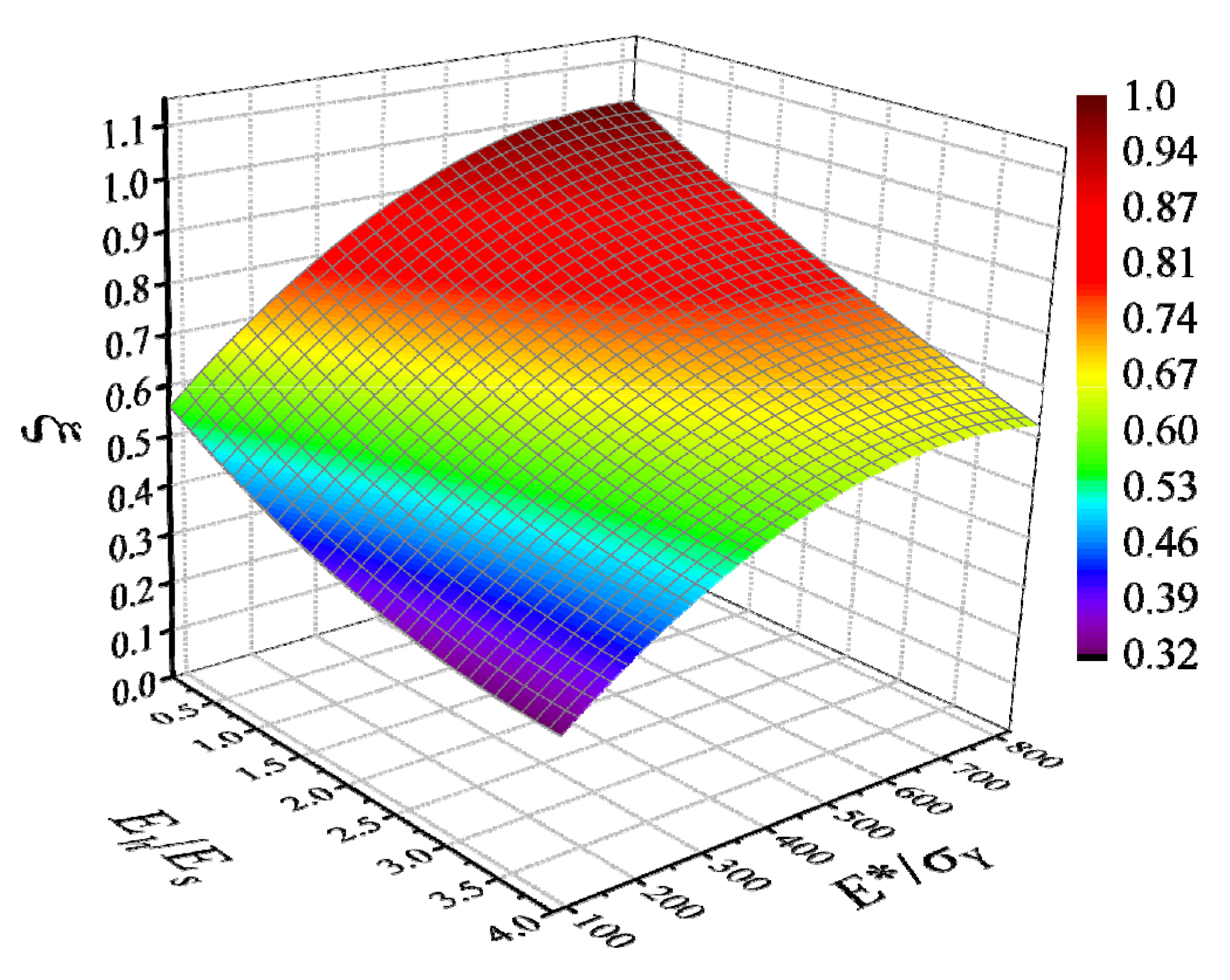
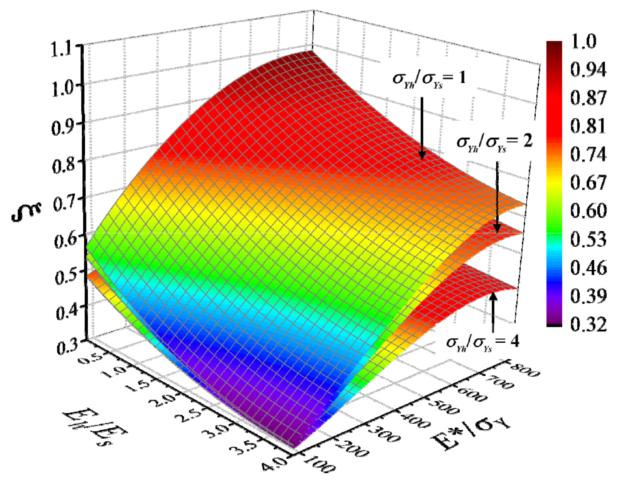
3. Influence of Spherical Elastic–Plastic Contact Deformation

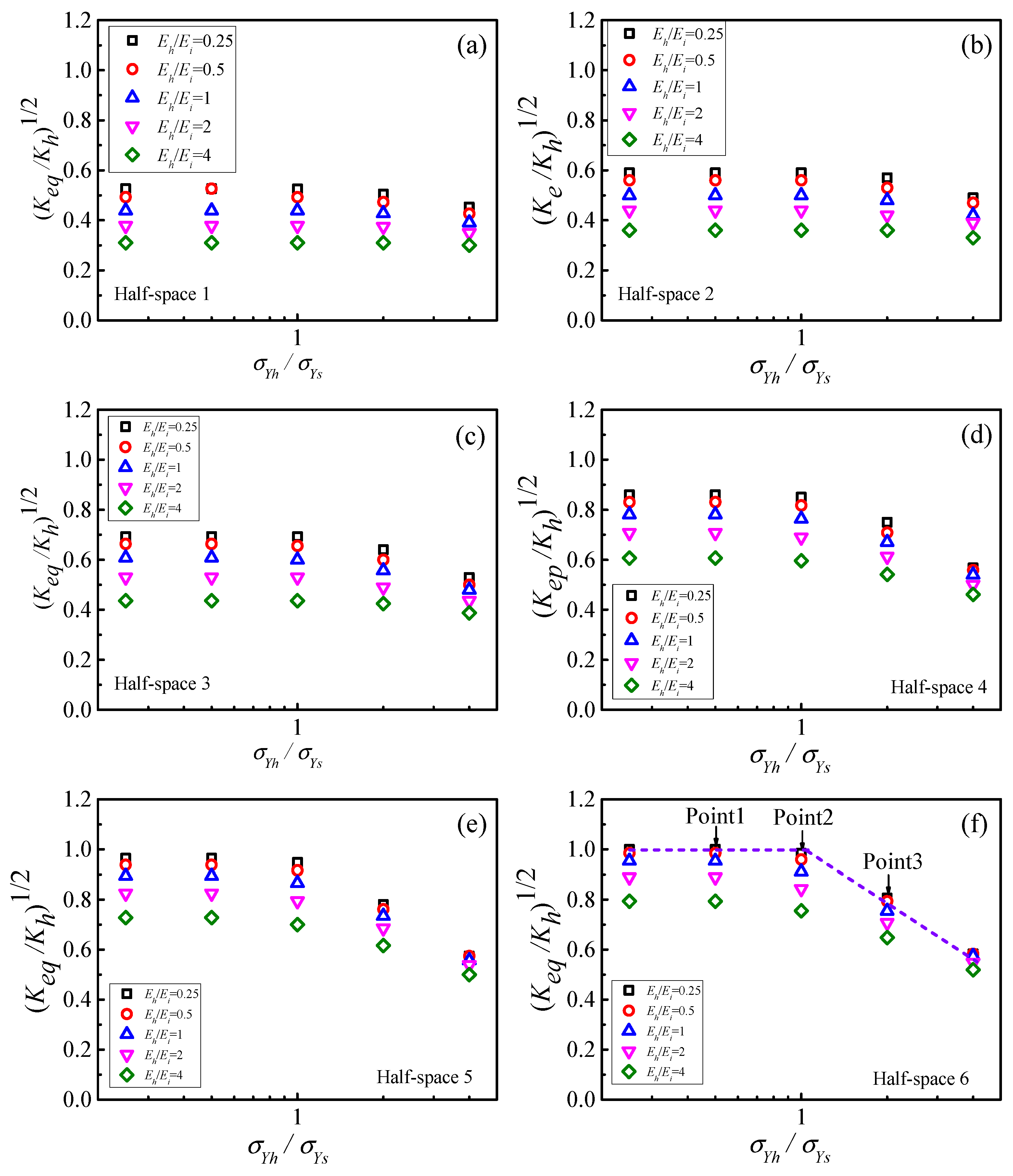
3.1. Influence of Spherical Elastic Modulus

In order to investigate the effect of sphere modulus of elasticity, five spheres with the modulus of elasticity of 30, 120, 206, 400, and 2000 GPa were selected to simulate the impact of the same half-space with the rest of the dimensions and material properties as in Table 1. The elastic modulus ratios E h / E s of the half-space to the sphere for the six cases are 6.87, 1.72, 1.0, 0.52, and 0.1, respectively. The calculated loading and unloading curves of the impact force versus the indentation are shown in Figure 3.
For the five impact cases, the linear contact stiffness K h is the same due to the constant sphere diameter and the yield strength of the half-space, which is calculated from Equation (2), with K h = 169.33   M N / m . In Figure 3, the dashed line represents the linear contact loading law. The FEM calculations in Figure 3 show that the actual contact stiffness is not constant and is related to E h / E s , with the maximum error occurring at E h / E s = 6.87, which is quite large.
As described in Figure 3, the F δ loading curve has significant linear characteristics if the equivalent contact stiffness K e q is as follows:
K e q = F m / δ m ,
where F m is the maximum contact force and δ m is the maximum indentation. The calculated K e q is 76.33, 12.46, 140.83, 154.64, and 170.13 MN/m for the five cases, and the maximum deviation from K h = 169.33   M N / m is 55%. Therefore, the effect of sphere elastic modulus needs to be considered.

3.2. Influence of Sphere Yield Strength

To investigate the effect of sphere yield strength, five spheres with yield strengths of 135, 270, 540, 1080, and 2160 MPa were selected for simulation of impacts of the same half-space. The remaining dimensions and material properties are consistent with Table 1. The ratios σ Y h / σ Y s of the yield strengths of the half-space to that of the sphere for the five cases are 2.04, 1.02, 1.02, 0.25, and 0.13, respectively. The loading and unloading curves of the computed impact force versus the indentation are shown in Figure 4.
Observing Figure 4, it is evident that the F δ loading curve has significant linear characteristics. The K e q is 97.11, 139.62, 153.95, 153.95, and 153.95 MN/m for the five cases, and the maximum deviation from K h = 169.33 M N / m is 43%. Therefore, the effect of sphere yield stress needs to be considered.

4. New Linear Contact Loading Law

To obtain a new linear contact loading law that is closer to the actual one, the impact finite element simulation data of 150 half-space and spherical material combinations are used to construct a new linear contact loading law by obtaining a general expression for the equivalent contact stiffness K e q through formula fitting.

4.1. Impact Conditions

The dimensions of the half-space and spheres for the 150 impact scenarios are shown in Table 1, and the material properties are shown in Table 2. Six common metallic materials are chosen for the half-space, which cover a wide range of widely used metallic material properties. E h * / σ Y h represents the inverse of the effective yield strain of the half-space, where the reduced modulus of elasticity of the half-space is E h * = E h / ( 1 υ h 2 ) . For each half-space material, six half-space to sphere modulus of elasticity ratios, E h / E s = 0.1, 0.25, 0.5, 1.0, 2.0, and 4.0, and six half-space to sphere yield strength ratios, σ Y h / σ Y s = 0.1, 0.25, 0.5, 1.0, 2.0, and 4.0, were chosen.

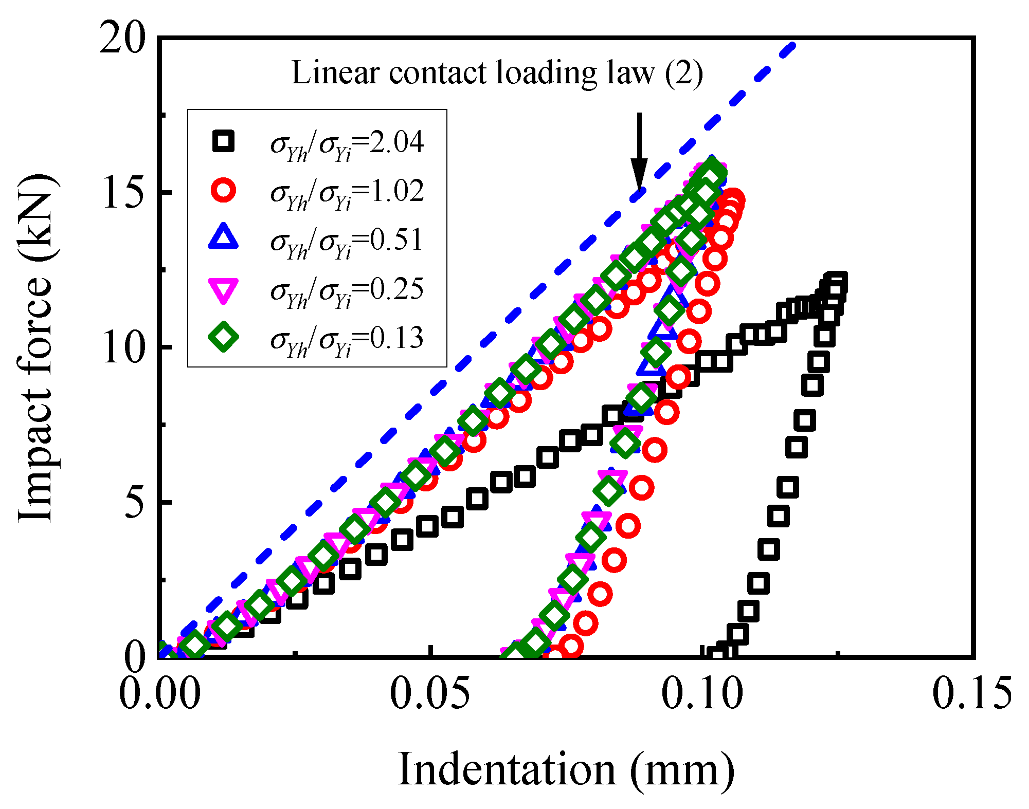
4.2. Piecewise Linear Feature

Figure 5 shows the results of the equivalent stiffness calculation. In Figure 5, the horizontal coordinate is the logarithm of σ Y h / σ Y s with base 10, and the vertical coordinate is K e q / K h . From Figure 5, it can be seen that K e q / K h = 1 is not universal and is usually less than or equal to 1 in most cases. As the yield strength of the sphere increases, K e q also experiences a corresponding increase. Similarly, a higher elastic modulus of the sphere results in a greater increase in K e q . The smaller the effective yield strain σ Y h / E h * of the half-space material, the larger K e q . The results in Figure 5 show that, for a given half-space material and E h / E s , the variation of K e q / K h exhibits segmented linear characteristics. Before a certain value of σ Y h / σ Y s = k 1 , it is a horizontal line segment, after that, it is a downward sloping line. Its slope decreases as the effective yield strain σ Y h / E h * of the half-space material increases.
To analyze the segmental linear characteristics, in Figure 5f, we can select three impact cases corresponding to point 1, point 2, and point 3 when E h / E s = 0.25. The calculated Mises stress distributions are depicted in Figure 6, enabling the observation of contact elastic–plastic deformation behaviors both before and after the intersection k. Among them, σ Y h = 275 MPa for the half-space and σ Y s for the spheres at points 1, 2, and 3 are 550, 275, and 137.5 MPa, respectively.
Figure 6a shows that the Mises stress of half-space 6 reaches the yield strength and exhibits elastic–plastic deformation. Meanwhile, the Mises stress of the sphere does not reach the yield strength and exhibits elastic deformation. This type of contact behavior can be viewed as an indentation type [31]. From Figure 6b, it can be seen that the Mises stresses of both the half-space 6 and the sphere reach the yield strength, and they exhibit elastic–plastic deformation at the same time. This contact behavior can be regarded as the combined type.
Figure 6c shows that the Mises stress of half-space 6 does not reach the yield strength, and the half-space exhibits elastic deformation; the Mises stress of the sphere reaches the yield strength and exhibits elastic–plastic deformation. This contact behavior can be viewed as a flattening type [31].
A similar careful analysis of all the impacts in Figure 5 reveal that σ Y h / σ Y s < k is of the indentation type and σ Y h / σ Y s > k is mostly of the indentation type. Sometimes σ Y h / σ Y s > k also appears as the combined type.
In summary, it can be concluded that K e q / K h for the indentation type is only related to E h / E s and E h * / σ Y h . The K e q / K h of the flattening and combined types is linearly related to σ Y h / σ Y s and is related to E h / E s and E h * / σ Y h . The emergence of segmented linearity is due to the behavior of different contact types.

4.3. Combined New Linear Contact Loading Law
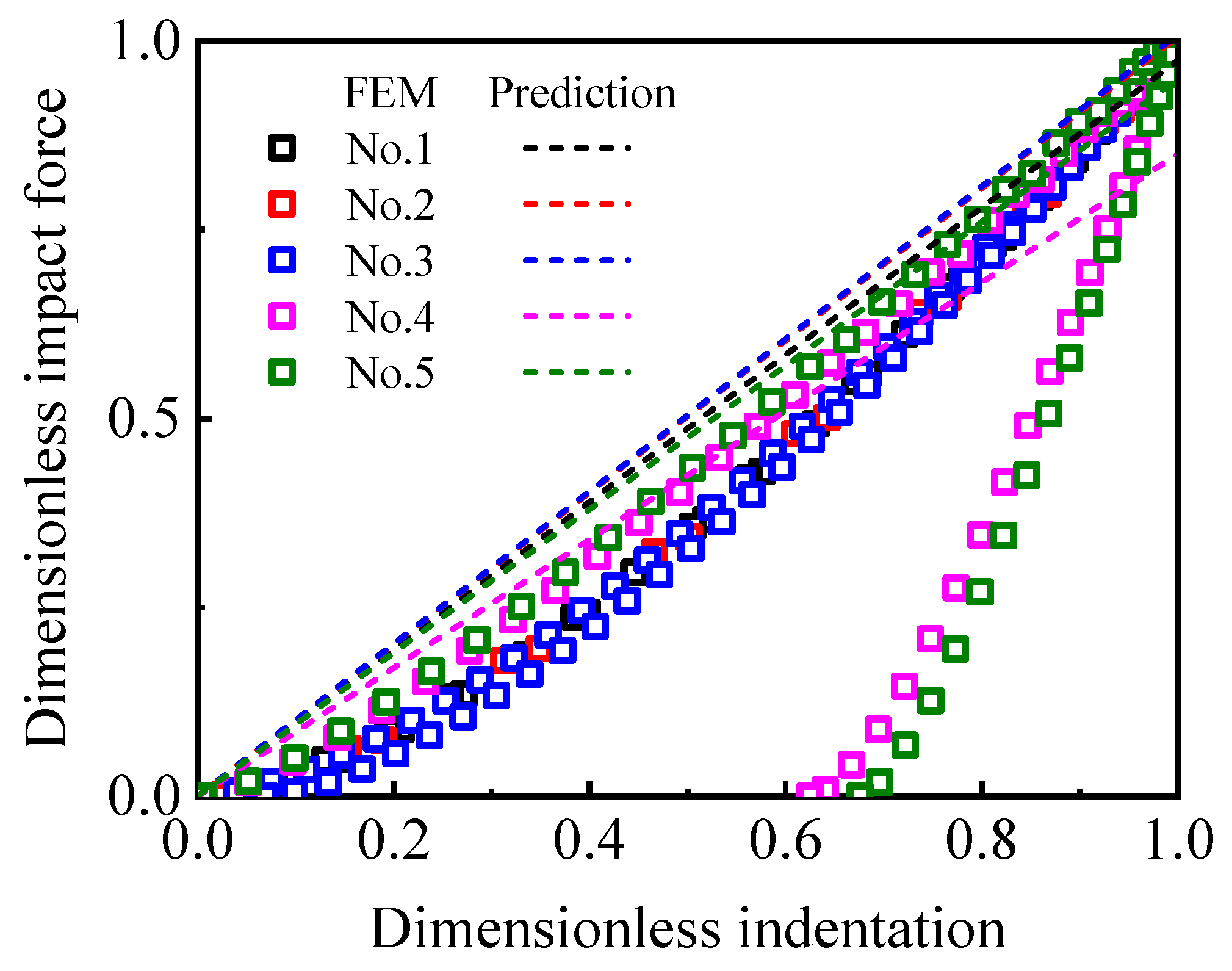
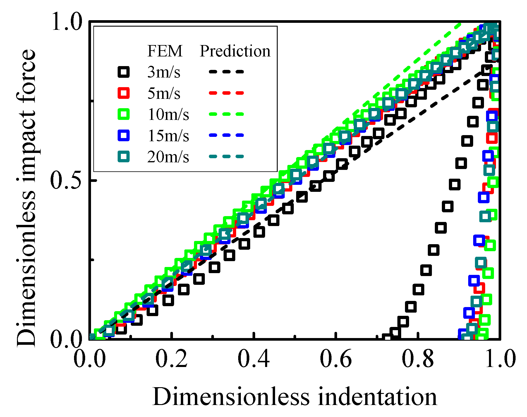
Since the linear loading law (1) cannot be applied to more general impact situations, a new linear contact loading law is proposed:
F = K e q δ ,
Due to the significant segmental linear character of K e q , the analytical expression of K e q can be obtained by fitting the finite element calculation results of 150 impacts in Section 3.1 as follows:
K e q / K h = ξ ,
ξ = a b E h / E s + c E h / E s 2 0 σ Y h / σ Y s < k d e σ Y h / σ Y s k σ Y h / σ Y s ,
where:
a = 0.44911 + 0.0014 E h * / σ Y h ( 8.71326 × 10 7 ) E h * / σ Y h 2 ,
b = 0.11699 ( 1.21254 × 10 12 ) E h * / σ Y h 3.62294 ,
c = 0.01557 ( 1.27765 × 10 5 ) E h * / σ Y h ,
where a , b , and c are the coefficients when 0 σ Y h / σ Y s < k , while d and e are the coefficients when k σ Y h / σ Y s :
d = λ β E h / E s + γ E h / E s 2 ,
e = ω η E h / E s + ψ E h / E s 2 ,
λ = 0.46508 + 0.00161 E h * / σ Y h ( 9.92809 × 10 7 ) E h * / σ Y h 2 ,
β = 0.10704 + 3.14676 × 10 4 E h * / σ Y h 6.92422 × 10 7 E h * / σ Y h 2 + 4.20916 × 10 10 E h * / σ Y h 3 ,
γ = 0.01387 + 2.8986 × 10 5 E h * / σ Y h 7.95567 × 10 8 E h * / σ Y h 2 + 5.35956 × 10 11 E h * / σ Y h 3 ,
ω = 0.00439 + ( 2.87402 × 10 4 ) E h * / σ Y h ( 1.5494 × 10 7 ) E h * / σ Y h 2 ,
η = 0.00714 + ( 6.1706 × 10 5 ) E h * / σ Y h ( 4.51026 × 10 8 ) E h * / σ Y h 2 ,
ψ = 9.89625 × 10 4 + 6.36574 × 10 6 E h * / σ Y h ( 4.51709 × 10 9 ) E h * / σ Y h 2 ,
the intersection point k of two lines is as follows:
k = 1 e d a + b E h / E s c E h / E s 2 ,
it follows that the following is true:
K e q = 2 π R ξ 2 p 0 ,
the fitting errors of the K e q for all 150 impacts were less than 5.9%.
To clearly illustrate the variations of ξ , Equation (8) is graphed as a response surface. For 0 σ Y h / σ Y s < k , the response surface is shown in Figure 7. It can be seen that ξ   m o n o t o n e l y d e c r e a s e s as E h * / σ Y h decreases or E h / E s increases. For large E h * / σ Y h , ξ almost linearly varies with E h / E s . For small E h * / σ Y h , ξ varies parabolically with E h / E s as a parabola. For a given E h / E s , the variation of ξ is dominated by the parabolic forms.
For k σ Y h / σ Y s , the response surfaces for σ Y h / σ Y s = 1, 2, and 4 are shown in Figure 8. It can be seen that ξ   m o n o t o n e l y   d e c r e a s e s as E h * / σ Y h decreases or E h / E s increases. ξ   a l s o   m o n o t o n e l y   d e c r e a s e s as σ Y h / σ Y s increases. For a given σ Y h / σ Y s and a given E h * / σ Y h , ξ varies parabolically with E h / E s . For a given σ Y h / σ Y s and a given E h / E s , the variation of ξ is dominated by the parabolic forms.

4.4. Verification

Five sphere-half-space impact cases with different material combinations are selected for finite element calculations to further verify the general applicability of the linear contact loading law (10). The material properties, dimensions, constraints, impact velocities v 0 , and initial impact energy E 0 of the spheres and half-spaces for the five impact cases are listed in Table 3. The results of the calculations are shown in Figure 9, which is chosen to be dimensionless in terms of the maximum impact force and the maximum indentation.
From Figure 9, it can be seen that the predictions by the new linear contact loading law (10) match the finite element calculations. The predicted values of the maximum impact forces are calculated by using the linear contact loading law (10) based on the indentation δ m at the unloading moment of the finite element. The comparison between the predicted values and the finite element calculation results is shown in Table 4, with a maximum error of 15.2% and an average error of 4.8%. When the initial impact energy is less than 1.5 J, the maximum error is less than 5%.
To verify the linear contact loading law (10) for higher impact velocities, five sphere-half-space impact cases under different impact velocities are selected for finite element calculations to further verify the general applicability of the linear contact loading law (10). The material properties, dimensions, constraints, and impact velocities v 0 of the spheres and half-spaces for the five impact cases are shown in Table 5. The results of the calculations are shown in Figure 10, which was chosen to be dimensionless in terms of the maximum impact force and the maximum indentation.
From Figure 10, it can be seen that the predictions by the new linear contact loading law (10) match the finite element calculations. The predicted values of the maximum impact forces are calculated by using the linear contact loading law (10) based on the indentation δ m at the unloading moment of the finite element. The comparison between the predicted values and the finite element calculation results is shown in Table 6, with a maximum error of 11% and an average error of 4.3%.

5. Conclusions

In this paper, the problem of an elastic–plastic sphere impacting an elastic–plastic half-space at low speed and low energy is investigated by using the finite element method (FEM), and the conclusions of this study are as follows:
The finite element calculation results show that the loading curves deviate significantly from the original linear contact loading law, mainly because the effects of sphere elasticity and yield strength are not considered.
The finite element calculations of 150 sphere-half-space impacts reveal that the ratio of the equivalent contact stiffness to the yield strengths of the sphere and the half-space exhibits two distinct segmental linear characteristics. The first segment shows a horizontal line, and the second segment shows a diagonal line. The first segment is in the form of indentation contact, and the second segment mainly presents the form of flattening contact.
Based on the finite element calculation results, the fitting method proposes a new linear contact law, which provides a theoretical model for the rapid calculation of the contact response of complex elastic–plastic impacts.

Author Contributions

All authors named in the manuscript have made a significant contribution to the manuscript. Each author’s contributions are listed. Conceptualization, X.Y. and H.Y.; methodology, X.Y. and H.Y; software, Y.G.; validation, H.Y., C.G., and X.D.; writing—original draft preparation, H.Y.; writing-review and editing, X.Y., C.W., and H.Z.; project administration, H.D., H.W. and X.Y; funding acquisition, H.D.; All authors have read and agreed to the published version of the manuscript.

Funding

This research was funded by the National Natural Science Foundation of China (Grant No. 11902143) and the APC was funded by the National Natural Science Foundation of China (Grant No. 12002164).

Institutional Review Board Statement

Not applicable.

Informed Consent Statement

Not applicable.

Data Availability Statement

The data presented in this study are available upon request from the corresponding author.

Acknowledgments

This work was supported by the National Natural Science Foundation of China (Grant No. 11902143) and the National Natural Science Foundation of China (Grant No. 12002164).

Conflicts of Interest

The authors declare no conflicts of interest.

References

  1. Goldsmit, W. The Theory and Physical Behavior of Colliding Solids; Arnold: London, UK, 1960. [Google Scholar]
  2. Johnson, K. The correlation of indentation experiments. J. Mech. Phys. Solids 1970, 18, 115–126. [Google Scholar] [CrossRef]
  3. Amdahl, J. Impact from ice floes and icebergs on ships and offshore structures in Polar Regions. In IOP Conference Series: Materials Science and Engineering, 2019; IOP Publishing: Bristol, UK, 2019; p. 012039. [Google Scholar]
  4. Krag, H.; Serrano, M.; Braun, V.; Kuchynka, P.; Catania, M.; Siminski, J.; Schimmerohn, M.; Marc, X.; Kuijper, D.; Shurmer, I. A 1 cm space debris impact onto the sentinel-1a solar array. Acta Astronaut. 2017, 137, 434–443. [Google Scholar] [CrossRef]
  5. Nishikawa, M.; Hemmi, K.; Park, S.; Nadabe, T.; Takeda, N. Finite element analysis on the impact-induced damage of composite fan blades subjected to a bird strike. Trans. Jpn. Soc. Aeronaut. Space Sci. 2011, 54, 238–245. [Google Scholar] [CrossRef]
  6. Lu, X.; Liu, X.; Li, Y.; Zhang, Y.; Zuo, H. Simulations of airborne collisions between drones and an aircraft windshield. Aerosp. Sci. Technol. 2020, 98, 105713. [Google Scholar] [CrossRef]
  7. Han, M.-G.; Chang, S.-H. Evaluation of structural integrity of Type-III hydrogen pressure vessel under low-velocity car-to-car collision using finite element analysis. Compos. Struct. 2016, 148, 198–206. [Google Scholar] [CrossRef]
  8. Yang, B.; Chen, K.; Wang, D.-M.; Elchalakani, M. Experimental study on composite beam with various connections under midspan impact scenarios. J. Struct. Eng. 2022, 148, 04022158. [Google Scholar] [CrossRef]
  9. Zhang, W.; Qin, Q.; Li, J.; Li, K.; Poh, L.; Li, Y.; Zhang, J.; Xie, S.; Chen, H.; Zhao, J. Deformation and failure of hybrid composite sandwich beams with a metal foam core under quasi-static load and low-velocity impact. Compos. Struct. 2020, 242, 112175. [Google Scholar] [CrossRef]
  10. Caliskan, U.; Apalak, M.K. Flexural impact response and damage detection of composite sandwich beam with various PVC foam cores. Mech. Adv. Mater. Struct. 2022, 29, 1276–1293. [Google Scholar] [CrossRef]
  11. Yu, T.; Zhang, L. Plastic Bending: Theory and Applications; World Scientific: London, UK, 1996; Volume 2. [Google Scholar]
  12. Zyczkowski, M. Combined Loadings in the Theory of Plasticity; Springer Science & Business Media: Berlin/Heidelberg, Germany, 1981. [Google Scholar]
  13. Iandiorio, C.; Salvini, P. Elastic-plastic analysis with pre-integrated beam finite element based on state diagrams: Elastic-perfectly plastic flow. Eur. J. Mech. -A/Solids 2023, 97, 104837. [Google Scholar] [CrossRef]
  14. Yi, G.; Liang, Y.; Wang, C.; Xu, J. Evolution of Residual Stress Based on Curvature Coupling in Multi-Roll Levelling. Appl. Sci. 2019, 9, 4975. [Google Scholar] [CrossRef]
  15. Stronge, W.J. Impact Mechanics; Cambridge University Press: Cambridge, UK, 2018. [Google Scholar]
  16. Minamoto, H.; Seifried, R.; Eberhard, P.; Kawamura, S. Analysis of repeated impacts on a steel rod with visco-plastic material behavior. Eur. J. Mech. -A/Solids 2011, 30, 336–344.
  17. Zhang, L.; Yin, X.; Yang, J.; Wang, H.; Deng, Q.; Yu, B.; Hao, Q.; Ding, H.; Qi, X.; Jin, T. Transient impact response analysis of an elastic–plastic beam. Appl. Math. Model. 2018, 55, 616–636. [Google Scholar] [CrossRef]
  18. Du, Y.; Wang, S. Energy dissipation in normal elastoplastic impact between two spheres. J. Appl. Mech. 2009, 76, 061010. [Google Scholar] [CrossRef]
  19. Patil, D.; Higgs, C.F. A coefficient of restitution model for sphere–plate elastoplastic impact with flexural vibrations. Nonlinear Dyn. 2017, 88, 1817–1832. [Google Scholar] [CrossRef]
  20. Thornton, C.; Cummins, S.J.; Cleary, P.W. On elastic-plastic normal contact force models, with and without adhesion. Powder Technol. 2017, 315, 339–346. [Google Scholar] [CrossRef]
  21. Brake, M. An analytical elastic-perfectly plastic contact model. Int. J. Solids Struct. 2012, 49, 3129–3141. [Google Scholar] [CrossRef]
  22. Larsson, P.-L.; Olsson, E. A numerical study of the mechanical behavior at contact between particles of dissimilar elastic–ideally plastic materials. J. Phys. Chem. Solids 2015, 77, 92–100. [Google Scholar] [CrossRef]
  23. Martin, C.; Bouvard, D. Isostatic compaction of bimodal powder mixtures and composites. Int. J. Mech. Sci. 2004, 46, 907–927. [Google Scholar] [CrossRef]
  24. Hertz, H. Ueber die Berührung fester elastischer Körper. 1882. [Google Scholar]
  25. Dong, X.; Yin, X.; Deng, Q.; Yu, B.; Wang, H.; Weng, P.; Chen, C.; Yuan, H. Local contact behavior between elastic and elastic–plastic bodies. Int. J. Solids Struct. 2018, 150, 22–39. [Google Scholar] [CrossRef]
  26. Kogut, L.; Komvopoulos, K. Analysis of the spherical indentation cycle for elastic–perfectly plastic solids. J. Mater. Res. 2004, 19, 3641–3653. [Google Scholar] [CrossRef]
  27. Chen, J.; Zhang, W.; Liu, D.; Wang, C.; Zhu, L. Loading–Unloading Behavior of a Spherical Contact for Varying Tangent Modulus and Yield Strength. J. Appl. Mech. 2023, 90, 021002. [Google Scholar] [CrossRef]
  28. Jackson, R.L.; Green, I. A finite element study of elasto-plastic hemispherical contact against a rigid flat. J. Trib. 2005, 127, 343–354. [Google Scholar] [CrossRef]
  29. Kogut, L.; Etsion, I. Elastic-plastic contact analysis of a sphere and a rigid flat. J. Appl. Mech. 2002, 69, 657–662. [Google Scholar] [CrossRef]
  30. Becker, V.; Kamlah, M. A theoretical model for the normal contact force of two elastoplastic ellipsoidal bodies. J. Appl. Mech. 2021, 88, 031006. [Google Scholar] [CrossRef]
  31. Ghaednia, H.; Pope, S.A.; Jackson, R.L.; Marghitu, D.B. A comprehensive study of the elasto-plastic contact of a sphere and a flat. Tribol. Int. 2016, 93, 78–90. [Google Scholar] [CrossRef]
  32. Taljat, B.; Zacharia, T.; Haggag, F. Analysis of ball-indentation load-depth data: Part I. Determining elastic modulus. J. Mater. Res. 1997, 12, 965–974. [Google Scholar]
  33. Taljat, B.; Zacharia, T.; Kosel, F. New analytical procedure to determine stress-strain curve from spherical indentation data. Int. J. Solids Struct. 1998, 35, 4411–4426. [Google Scholar] [CrossRef]
  34. Knapp, J.; Follstaedt, D.; Myers, S.; Barbour, J.; Friedmann, T. Finite-element modeling of nanoindentation. J. Appl. Phys. 1999, 85, 1460–1474. [Google Scholar] [CrossRef]
  35. Ghaednia, H.; Mifflin, G.; Lunia, P.; O‘Neill, E.O.; Brake, M.R. Strain hardening from elastic-perfectly plastic to perfectly elastic indentation single asperity contact. Front. Mech. Eng. 2020, 6, 60. [Google Scholar] [CrossRef]
  36. Weng, P.; Yin, X.; Hu, W.; Yuan, H.; Chen, C.; Ding, H.; Yu, B.; Xie, W.; Jiang, L.; Wang, H. Piecewise linear deformation characteristics and a contact model for elastic-plastic indentation considering indenter elasticity. Tribol. Int. 2021, 162, 107114. [Google Scholar] [CrossRef]
  37. Majeed, M.A.; Yigit, A.S.; Christoforou, A.P. Modeling and analysis of elastoplastic impacts on supported composites. Key Eng. Mater. 2011, 471, 367–372. [Google Scholar] [CrossRef]
Figure 1. 2D axisymmetric finite element model. (a) Global mesh diagram and (b) enlarged view of the contact area.
Applsci 14 05018 g001
Figure 2. Comparison between simulations and the Hertz solutions.
Applsci 14 05018 g002
Figure 3. Five F δ curves with five E h / E s .
Applsci 14 05018 g003
Figure 4. Five F δ curves with five σ Y h / σ Y s .
Applsci 14 05018 g004
Figure 5. Piecewise linear features for six half-space materials for K e q / K h as a function of σ Y h / σ Y s varies with E h / E s . (af) represents half-space 1, 2, 3, 4, 5 and 6, respectively.
Applsci 14 05018 g005
Figure 6. Three Von Mises stress distributions of half-space 6 and the spheres (a) σ Y h / σ Y s = 0.5 ; (b) σ Y h / σ Y s = 1 ; (c) σ Y h / σ Y s = 2 .
Applsci 14 05018 g006
Figure 7. Response surface for 0 σ Y h / σ Y s < k .
Applsci 14 05018 g007
Figure 8. Response surfaces for 0 σ Y h / σ Y s < k as σ Y h / σ Y s = 1, 2, and 4, respectively.
Applsci 14 05018 g008
Figure 9. F δ curves for the five impacts.
Applsci 14 05018 g009
Figure 10. F δ curves for the five impact velocities.
Applsci 14 05018 g010
Table 1. Dimensions and material properties.
Half-SpaceSphere
r × h 800 × 800 m m R 35 m m
m s 1.4 k g
E h 206 G P a E s 206 G P a
σ Y h 275 M P a σ Y s 275 M P a
υ h 0.3 υ s 0.3
ρ h 7800 k g / m 3 ρ s 7800 k g / m 3
Table 2. Material properties of half-space and spheres for different impact scenarios.
Half-Space123456
E h G P a 60123210207206206
σ Y h M P a 80010701079540345275
υ h 0.30.30.30.30.30.3
υ s 0.30.30.30.30.30.3
ρ h k g / m 3 780078007800780078007800
ρ s k g / m 3 780078007800780078007800
E h * / σ Y h 82.42126.32213.87421.25656.16823.18
E h / E s 0.25–40.25–40.25–40.25–40.25–40.25–4
σ Y h / σ Y s 0.25–40.25–40.25–40.25–40.25–40.25–4
Table 3. Dimensions and material properties of spheres and half-space for five impact scenarios.
Case12345
L × H   m m 2002008001000800
E h   G P a 206207206207206
σ Y h   M P a 275540345540345
υ h 0.30.30.30.30.3
ρ h   k g / m 3 78007800780078007800
R  m m 105403535
E s   G P a 824207412414206
σ Y s   M P a 110010803451080345
υ s 0.30.30.30.30.3
ρ s   k g / m 3 78007800780078007800
v 0   m / s 0.60.50.721.5
E 0   J 0.0321.625 × 10−40.5122.8021.576
Table 4. Comparison of the maximum impact force (N) for five sphere-half-space impact cases with different material combinations for lower impact velocities.
Num12345
δ m   m m 0.0270.0130.1070.1540.143
FEM N 1327.1370.521,709.541,521.324,335.3
prediction N 1292.4372.621,895.235,208.623,174.9
error % 2.60.60.815.24.8
Table 5. Dimensions and material properties of spheres and half-space for five impact velocities.
Num12345
L × H   m m 800800800800800
E h   G P a 120206206206206
σ Y h   M P a 320345345345345
υ h 0.30.30.30.30.3
ρ h   k g / m 3 52007800780078007800
R   m m 1010101010
E s   G P a 4101021027070
σ Y s   M P a 690100100140140
υ s 0.30.30.30.30.3
ρ s   k g / m 3 78007800780027002700
v 0 m / s 35101520
E(J)0.1470.4081.6341.2722.262
Table 6. Comparison of the maximum impact force (N) for five sphere-half-space impact cases with different material combinations for higher impact velocities.
Num12345
v 0   m / s 35101520
δ m   m m 0.0780.2000.4050.3140.420
FEM N 4139.24041.87724.38068.010,616.3
prediction N 4236.04302.08687.77886.610,523.7
error % 2.3%6%11%2.2%0.09%
Disclaimer/Publisher’s Note: The statements, opinions and data contained in all publications are solely those of the individual author(s) and contributor(s) and not of MDPI and/or the editor(s). MDPI and/or the editor(s) disclaim responsibility for any injury to people or property resulting from any ideas, methods, instructions or products referred to in the content.

