Article

Research on Multi-Directional Spalling Evolution Analysis Method for Angular Ball Bearing

1
School of Mechanical and Electrical Engineering, University of Electronic Science and Technology of China, Chengdu 611731, China
2
Center for System Reliability and Safety, University of Electronic Science and Technology of China, Chengdu 611731, China
3
Beijing Aeronautical Technology Research Center, Beijing 100076, China
*
Author to whom correspondence should be addressed.
Appl. Sci. 2024, 14(12), 5072; https://doi.org/10.3390/app14125072
Submission received: 11 April 2024 / Revised: 22 May 2024 / Accepted: 4 June 2024 / Published: 11 June 2024
(This article belongs to the Section Mechanical Engineering)

Abstract

:
The prediction of spalling failure evolution in the lifespan of aeroengine bearings is crucial for en-suring the safe return of aircrafts after such failures occur. This study examines the spalling failure evolution process in bearings by integrating the proposed spalling region contact stress analysis model with the multi-directional subsurface crack extension analysis model. The results elucidate the general pattern of spalling expansion. Utilizing this methodology, the fatigue spalling fault evolution in bearings is thoroughly analyzed. Additionally, a two-dimensional model has been developed to simulate and analyze crack propagation in the critical direction of the spalling region, significantly enhancing the model’s computational efficiency.

1. Introduction

Fatigue spalling in aeroengine bearings constitutes a pivotal failure mode. This study explores the evolution of fatigue spalling faults, tracing their origins to the initial formation of cracks on the bearing raceway. Given the demanding environments experienced within aeroengines, bearings are exposed to increasingly complex loading scenarios. As a result, the raceway of the aeroengine’s main bearing requires enhanced surface specifications. Under cyclic loading conditions, subsurface cracks on the raceway gradually propagate and ultimately merge, culminating in spalling [1]. Once spalling initiates on the raceway during bearing operation, the spalling region tends to expand progressively, which severely compromises the reliability and safety of the bearing. Figure 1 shows the propagation of a spalling crack on a raceway during the evolution of a spalling fault.
The expansion of the subsurface crack will eventually lead to defects in the bearing material in this area and further expand the spalling region. This is known as spalling fault evolution. The evolving spalling of the bearing can ultimately lead to bearing failure, thus jeopardizing aircraft safety and posing risks to the pilot. Bearing spalling can be attributed to a multitude of factors, including imperfections introduced during manufacturing processes, excessive loading conditions, and inadequate maintenance practices. The primary cause of spalling propagation is the cyclic load experienced between the rolling elements and raceways within the bearing. While contemporary research efforts leverage data-driven approaches to monitor the inception of spalling, mechanistic insights into the spalling fault evolution process remain elusive [2,3]. Data-driven approaches have gained significant traction for addressing spalling failures on the raceway surface [4]. These methodologies and devices enable timely alerts regarding anomalous bearing conditions for aircrafts. However, for pilots engaged in flight missions, the critical aspect is whether there is sufficient time to return to base safely. Establishing a spalling fault evolution life prediction model for bearings enables calculating effective prognostics of the remaining useful life after spalling initiation. Such a model will play a significant role in planning the remaining flight mission and guiding maintenance schedules for aeroengine bearings.
In aeroengine bearings, spalling represents a predominant failure mode, attributed to their high-speed and high-load characteristics. The spalling region progressively enlarges due to the ongoing contact between the rolling elements and the raceways of the bearing [5,6,7]. The cyclic loading between the rolling elements and the raceway can exacerbate the spalling propagation process. Within aeroengine bearings operating under such intricate operating conditions, the direction and rate of spalling propagation become even more elusive to uncover. Steenbergen [8] explicitly demonstrated, through modeling and analysis of fatigue spalling on a railway, that fatigue spall crack propagation analysis is key in the modeling and analysis of spalling. Ren [9] combined finite element analysis with fracture mechanics models when modeling subsurface cracks in rolling bearings. By incorporating the specific loading characteristics of aeroengine bearings and iteratively updating the model, it is possible to complete a propagation analysis of spalling cracks.
Lubrication plays a critical and indispensable role in aeroengine bearings. To incorporate lubrication effects, this study directly analyzes the contact stress response under fully lubricated conditions in rolling bearings. Cen and Lugt [10] investigated the evolution of the lubrication film in high-speed rolling bearings. Vijay [11] further analyzed the influence of bearing material on the lubricating film. Madar [12] proposed a spalling size estimation method based on oil debris monitoring based on experimental data. In the analysis of spalling evolution in aeroengine bearings, it is essential to consider the lubrication effect of the bearing. The modeling and analysis should be conducted using the modified stress response value to accurately assess the impact of lubrication on spalling progression.
To establish a spalling evolution model for bearings, it is necessary to calculate the stress around the spalled area. Branch [13] revealed the effect of spalling on the contact stress of a bearing by performing finite element modeling and analysis of the impact process of the roller at the edge of the spalled area. Spalling not only has a direct impact on contact stress but also affects the vibration data of the bearing. Bai [14] conducted a detailed simulation of the microscopic expression of the spalling process by studying a microscopic spalling model of anisotropic veined gneiss. Toumi [15] developed a dynamic simulation model incorporating spalling to simulate the stress response of thrust ball bearings at the defect location and assessed the relationship between spalling size and load. Thibault [16] conducted simulations to analyze changes in bearing signals when spalling occurs on the outer ring of a bearing. Chen [17] established a model for identifying the size of inner and outer ring defects through spectrum analysis by modeling and testing. Liu [18] not only identified the defect location on a bearing raceway through spectrum analysis but also conducted feature modeling and analysis of the damage on the rollers. Moralesespejel [19] established a numerical calculation and simulation model for the stress response of the spalling region and studied the influence of the indentation on the spalling of cylindrical roller bearings. To establish a fatigue spalling evolution model, the stress response of the spalling area must first be calculated, and then, the rate of subsurface crack extension and spalling region expansion can be calculated.
To enhance the computational efficiency of this spalling fault evolution analysis, integration of contact analysis and subsurface crack propagation analysis is implemented. A finite element model for spalling evolution analysis, incorporating cracks, is established using the normal contact load as input. This approach allows for the analysis of the bearing spalling expansion rate and facilitates the prediction of the fatigue life evolution of the bearing spalling. The modeling and analysis process is depicted in the flowchart presented in Figure 2.

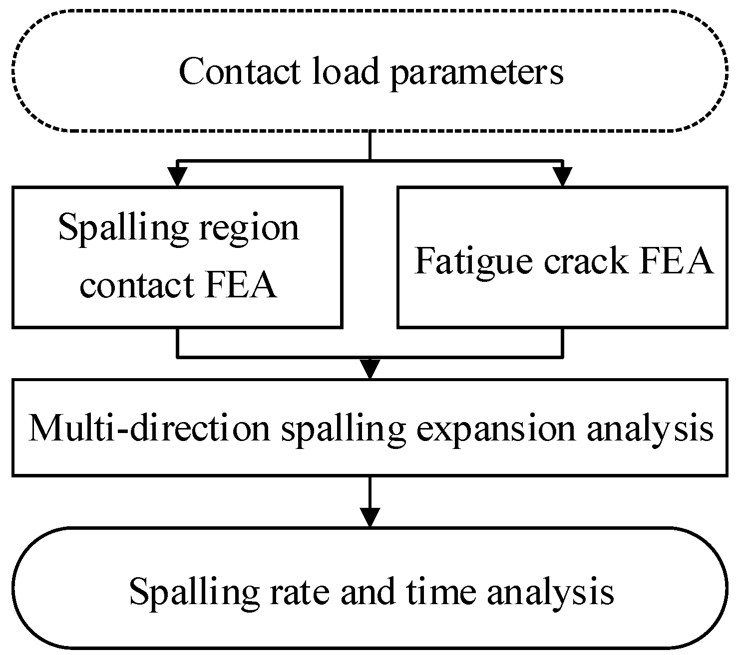
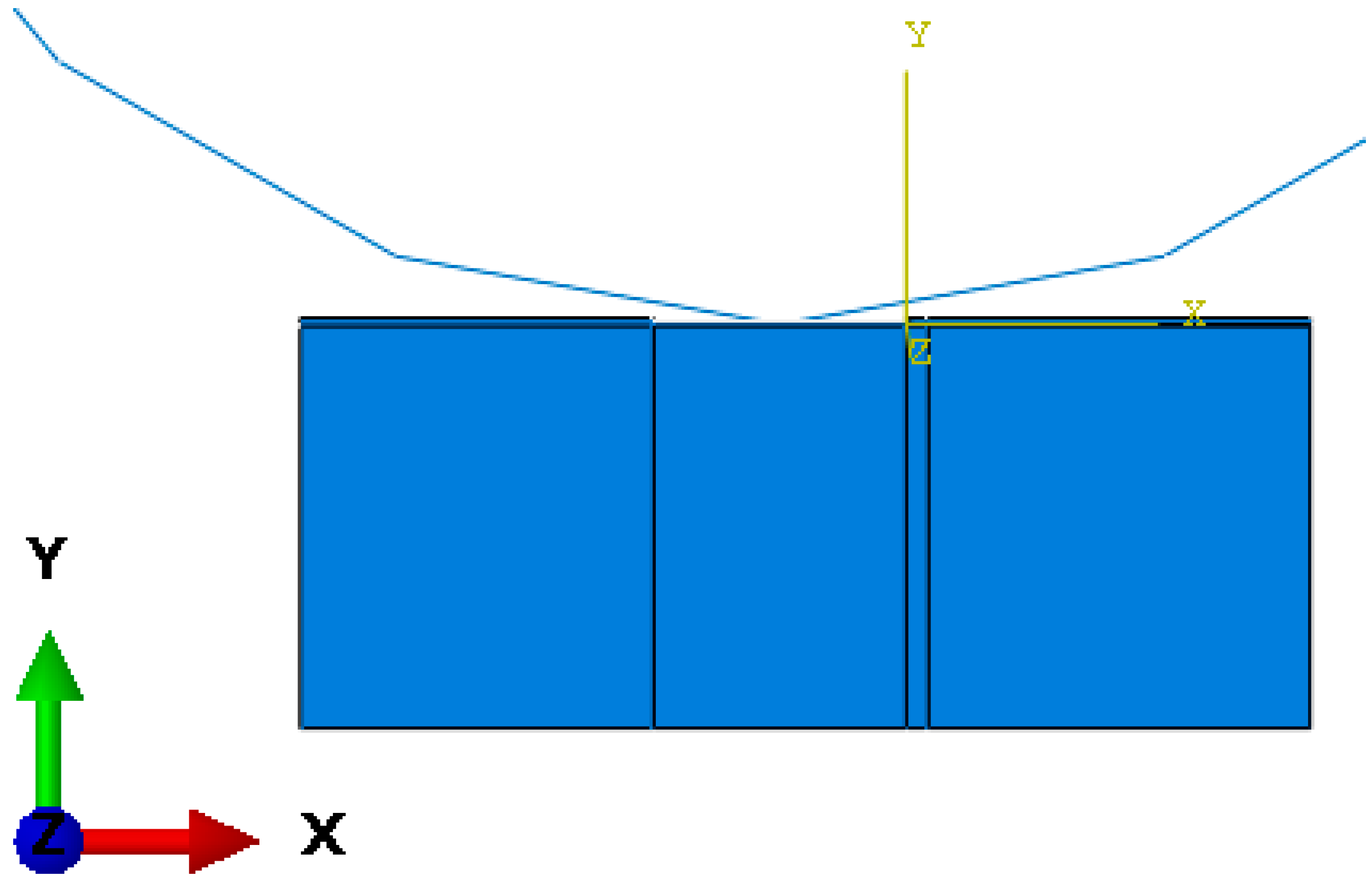
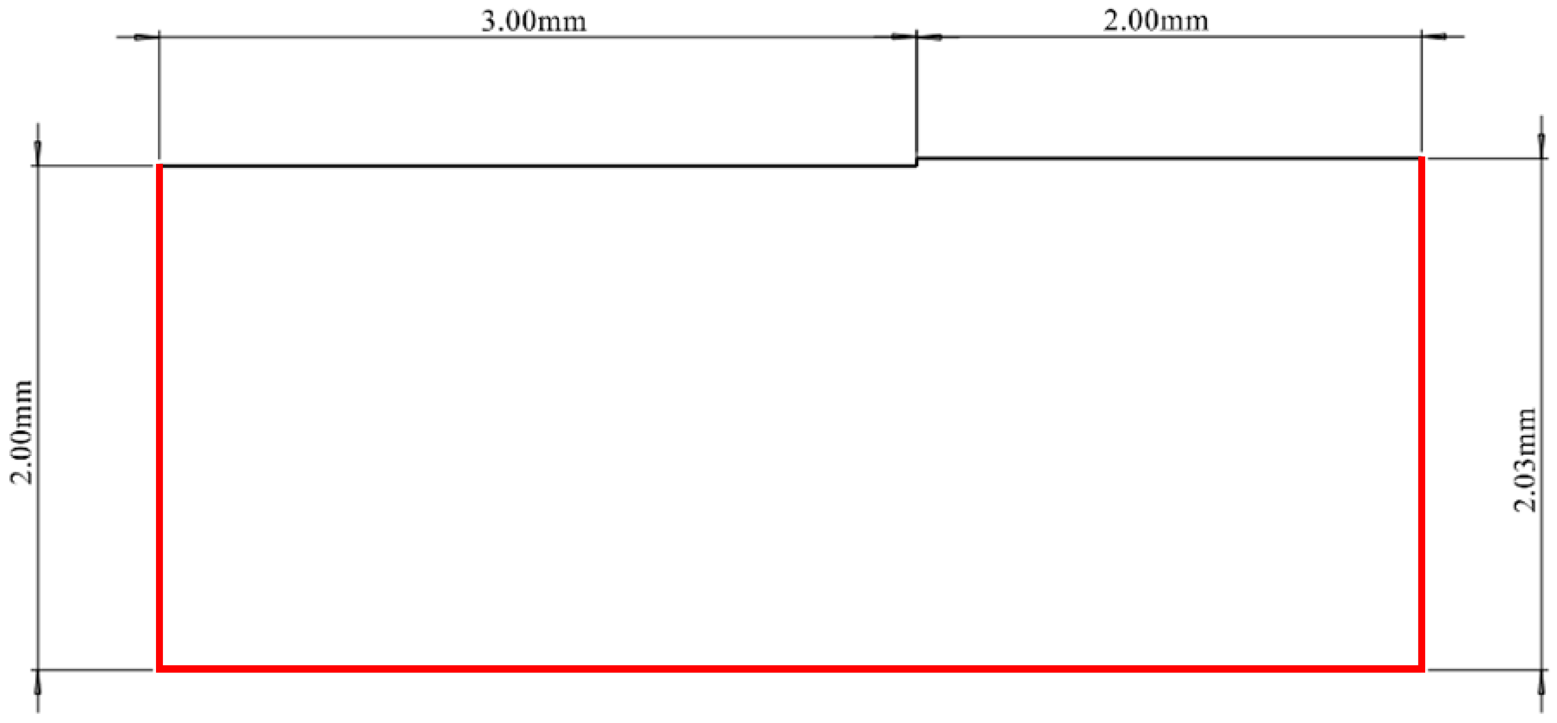
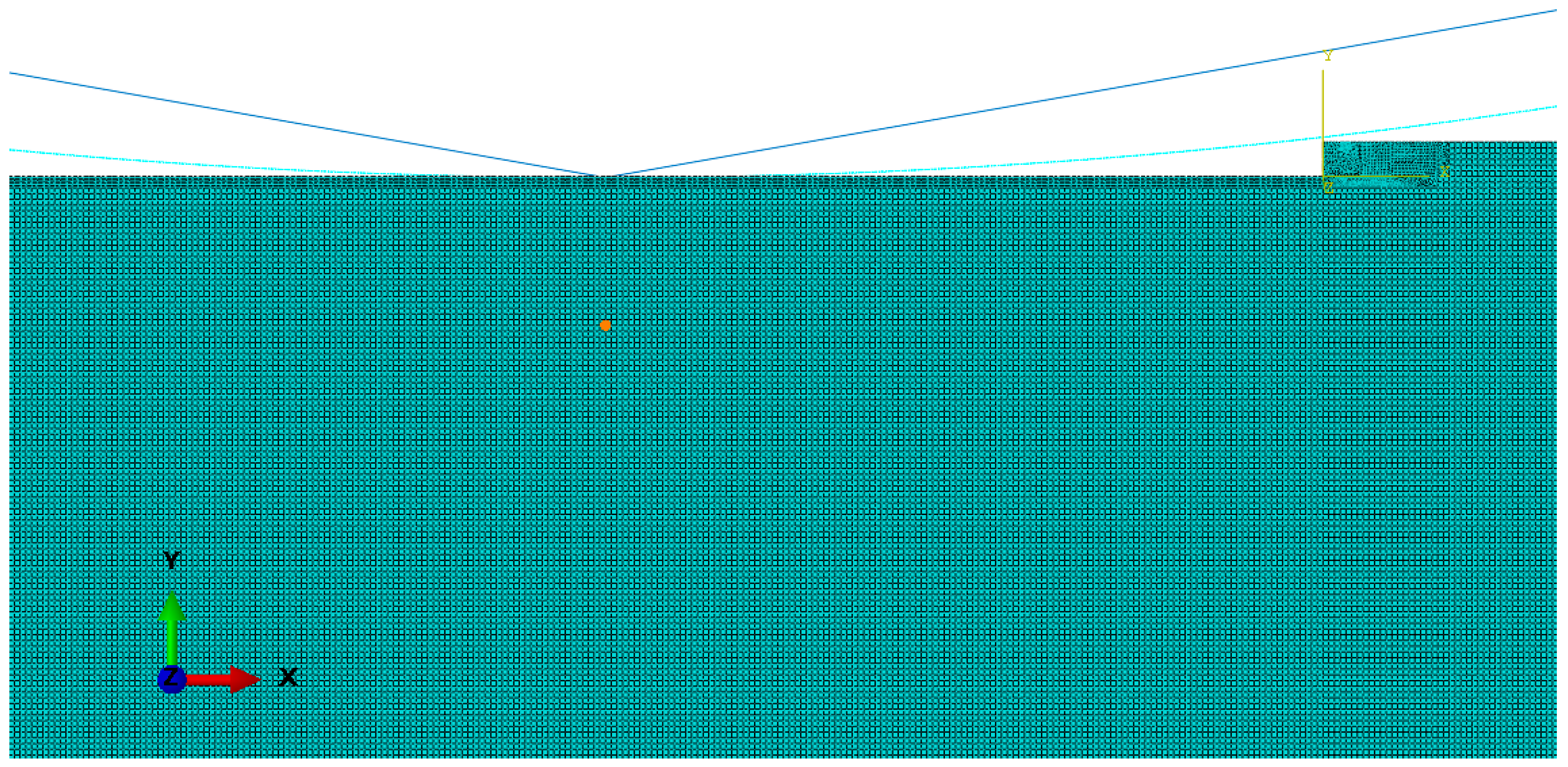
2. Spalling Region Contact FEA Model

To accurately compute the spalling evolution rate of a bearing while accounting for temperature and lubrication effects, the finite element simulation method is essential. In bearings where the inner ring is mobile, the position of the maximum stress point on the inner ring raceway shifts over time. Conversely, the location of the maximum stress point on the outer ring raceway remains static. This also makes the outer ring of the bearing more susceptible to spalling. Therefore, in the development of a fatigue spalling simulation model for a bearing’s outer raceway, simplifications can be made by selectively modeling only those areas identified as potential weak points. Figure 3 illustrates a simplified finite element model of the interaction between a roller and the outer raceway in the spalling region.
In reference [20], a three-dimensional crack propagation model is established. In this model, the center of the spalling region aligns with the maximum stress point on the outer ring of the bearing. The findings indicate that the crack torsion angle resulting from mode III crack propagation is generally within 10 degrees. Consequently, it is feasible to develop a two-dimensional crack propagation model that excludes considerations of mode III cracks. This simplified model can effectively analyze the evolution process of spalling faults in angular contact ball bearings.
In order to further simplify the analysis process and simulate the subsurface crack propagation process, a two-dimensional analytical model is developed. This model combines contact stress analysis of the spalling region with subsurface crack propagation analysis, further improving the computational efficiency. As shown in Figure 4, the constructed spalling simulation model is shown.
In the actual calculation, the normal deformation of the bearing roller on the contact surface is much smaller than that of the raceway, so the roller is set as a discrete rigid body in the model. The three faces of the raceway in the model are set to a completely fixed state. The size parameters and constraints of the model are shown in Figure 5.
In order to perform crack propagation analysis on the model, static analysis methods are employed to calculate the stress intensity factor (SIF) at the crack front. This approach allows for a significant reduction in simulation time while also enabling the model to be more easily integrated with the crack propagation module. The mesh division of the model is shown in Figure 6. In the model, CPS4R cells are used for meshing, and the cell length is refined to 0.002 mm at the contact point. The model uniformly employs quadrilateral meshes to facilitate model iteration and updating.
The model was constructed for a 7208AC angular contact ball bearing, and the stress response when the bearing roller rolls over the edge of the spalling region was simulated and calculated, as shown in the diagram in Figure 7.
The model obtains the contact parameter settings and normal force Q e between the roller and raceway based on the calculation results of the elastic hydrodynamic lubrication (EHL) model [21,22,23,24]. The force variation curve Q e of the roller calculated by the EHL model is shown in Figure 8.
When the radial load F z = 2000   N , the axial load F x = 10,000   N , and the rotating speed is 7000 rpm, the maximum contact force of the bearing is at the azimuth of 90°. Therefore, the contact stress around the spalling area is analyzed within ±6° before and after this position. In this study, the 7208AC bearing (AST Bearings, Parsippany, NJ, USA), which is widely used in the aerospace field, is used as the analysis object. An image of the 7208AC bearing is shown in Figure 9, and the specific structural parameters and working conditions are shown in Table 1.

3. Fatigue Crack FEA Model

The established two-dimensional contact stress analysis model is already capable of accurately calculating the stress response in multiple directions around a spalling zone. At the same time, the model can be effectively combined with crack propagation analysis methods. In the model, the propagation of cracks is primarily caused by the contact stress between the roller and the edge of the spalling region. Figure 10 shows the von Mises stress simulation of an initial spalling crack with an initial angle of 90° and a length of 0.01 mm at the edge of the spalling region after a propagation with a deflection angle of 55.92°. At this time, the initial crack depth is 0.02 mm.
In finite element simulation software, the contour integral method (CIM) is frequently utilized to calculate the SIF at the crack front. This method is a prevalent numerical technique specifically designed for determining the SIF, making it particularly well-suited for addressing crack problems in finite element analysis. The CIM involves the integration of the stress field along a contour that encircles the crack, thereby allowing computation of the SIF. This technique is versatile and can be applied to a wide range of crack types and loading conditions.
For a square spalling zone as shown in Figure 11, the four cracks propagating in different directions can be denoted as F, B, L, and R according to the actual rolling direction of the roller.
Through the established two-dimensional model, it is possible to analyze the subsurface crack extension in these four directions. In this model, the crack extension is mainly affected by the strain at the edge of the spalling region. To calculate the crack extension life, the propagation rate of the spalling crack can be obtained by the Paris formula [25]:
d a d N = C Δ K m
where d a / d N is the crack extension rate, C and m are material constants, and Δ K is the SIF range.
In the model, Δ K is mainly controlled by the extension of cracks of types I and II and can be defined as follows:
Δ K = K max K min
where K max is the maximum stress intensity factor and K min is the minimum stress intensity factor.
The criterion for determining whether crack extension has begun is given by the following formula:
Δ K > K th
where K th is the fatigue crack growth threshold.
The propagation rate of spalling cracks is influenced by several factors, including the stress intensity factor (SIF). In the established subsurface crack propagation analysis model of bearings, the analysis is mainly focused on type I and type II cracks. By combining the stress intensity factors K I and K II of type I and type II cracks, the equivalent stress intensity factor K eq can be calculated [25,26].
K eq = K I 2 + K II 2 0.5
By comprehensively considering the two crack types through K eq , the crack propagation rate can be calculated by d a / d N = C Δ K eq m . The deflection angle of the crack is mainly affected by SIFs K I and K II . The crack deflection angle can be calculated by the following [27]:
K I sin φ 0 + K II 3 cos φ 0 1 = 0
where φ 0 is in the range 70.5 , 70.5 .
To simulate the subsurface crack propagation process, it is necessary to use the established two-dimensional model to calculate the SIF value at the crack front when the roller rolls over the spalling region. The crack deflection angle is also calculated simultaneously. The flowchart of the multi-direction crack FEA model calculation is shown in Figure 12.
Load Q e is one of the key factors that affect the crack propagation direction and speed in the model. The parameter values in the coefficients of the Paris formula are C = 3.38 × 10 12 and m = 3 . The initial crack is located at an angle of 80° to the vertical direction with a depth of 0.02 mm when the value of Q e changes from 500 N to 2000 N; the SIF output by the model is shown in Figure 13.
Figure 13 shows the variation in the equivalent stress intensity factor K eq as the roller moves from left to right across the spalling region. When Q e = 1000   N , the maximum K eq value is located at x = 0.2683   mm . At this point, the crack extension criterion is satisfied. Therefore, it can be assumed that the crack extends at this moment. The deflection angle φ 0 and the crack propagation rate v 0 can be calculated at the same time. The whole process is repeated multiple times until the crack extension exceeds the surface of the roller raceway. Finally, the multi-directional crack FEA model was completed by iteratively calculating the propagation path and required time of cracks in multiple directions.

4. Multi-Direction Spalling Expansion Analysis

The analysis results from the EHL model indicate that the maximum stress point on the bearing’s outer ring is situated at the lowest point of the outer ring, with a contact angle of 30.2469°. Around this maximum stress point, an initial square spalling region with a depth of 0.03 mm is defined, encompassing an azimuth angle range of ±1° and a contact angle range of ±10°. Using the established multi-directional crack FEA model, the propagation of spalling in four directions within this region is examined.
The analysis continues with a scenario involving a crack of 0.02 mm depth at an initial angle of 90° relative to the vertical direction. The multi-directional crack FEA model facilitates the examination of spalling expansion in multiple directions by modifying the initial position and direction of motion of the roller. The progression of the crack, labeled as F, is analyzed as the roller moves from left to right. Conversely, the propagation of the crack labeled as B can be analyzed when the roller moves from right to left. In the case where the radial load F z = 2000   N , the axial load F x = 10,000   N , and the rotating speed is 7000 rpm, the crack propagation results for cracks labeled F and B are presented in Table 2 and Table 3, respectively.
For cracks labeled as L and R, a static analysis is required based on the initial spalling region width. When the roller is located at the point of maximum stress, the left and right edges of the spalling region are subjected to symmetrical stress when the effect of its self-rotation is ignored. When the roller rolls through the center of the spalling region, the forces are symmetrical in the L and R directions. At this time, the model’s left and right translation degrees of freedom are restricted, and Q e is changed to half of its original value for analysis. Figure 14 shows a schematic diagram of the roller position under symmetrical conditions, and Table 4 shows the crack propagation simulation results under symmetrical conditions.
The use of the simplified 2D model for the analysis of spalling cracks results in higher computational efficiency. This simplification method is feasible when the spalling region coincides with the weak points of the bearing. By analyzing the crack propagation in four directions, it was found that cracks labeled as F and B are more likely to propagate. Therefore, the crack B was analyzed to investigate the relationship between the propagation time and the initial crack angle. Table 5 summarizes the relationship between the initial crack angle and the time required for spalling to propagate 1 mm.
In the numerical simulation, when the initial angle exceeds 90°, the crack will propagate far away from the raceway surface, making it difficult for spalling to propagate. Figure 15 provides schematic representations of the spalling cracks for the three distinct initial angles.

5. Conclusions

In this study, the stress within a spalling region and the multi-directional propagation of spalling were analyzed, and the efficiency of the analysis was enhanced through further simplification of the model. The key conclusions drawn from this study are as follows:
(1)
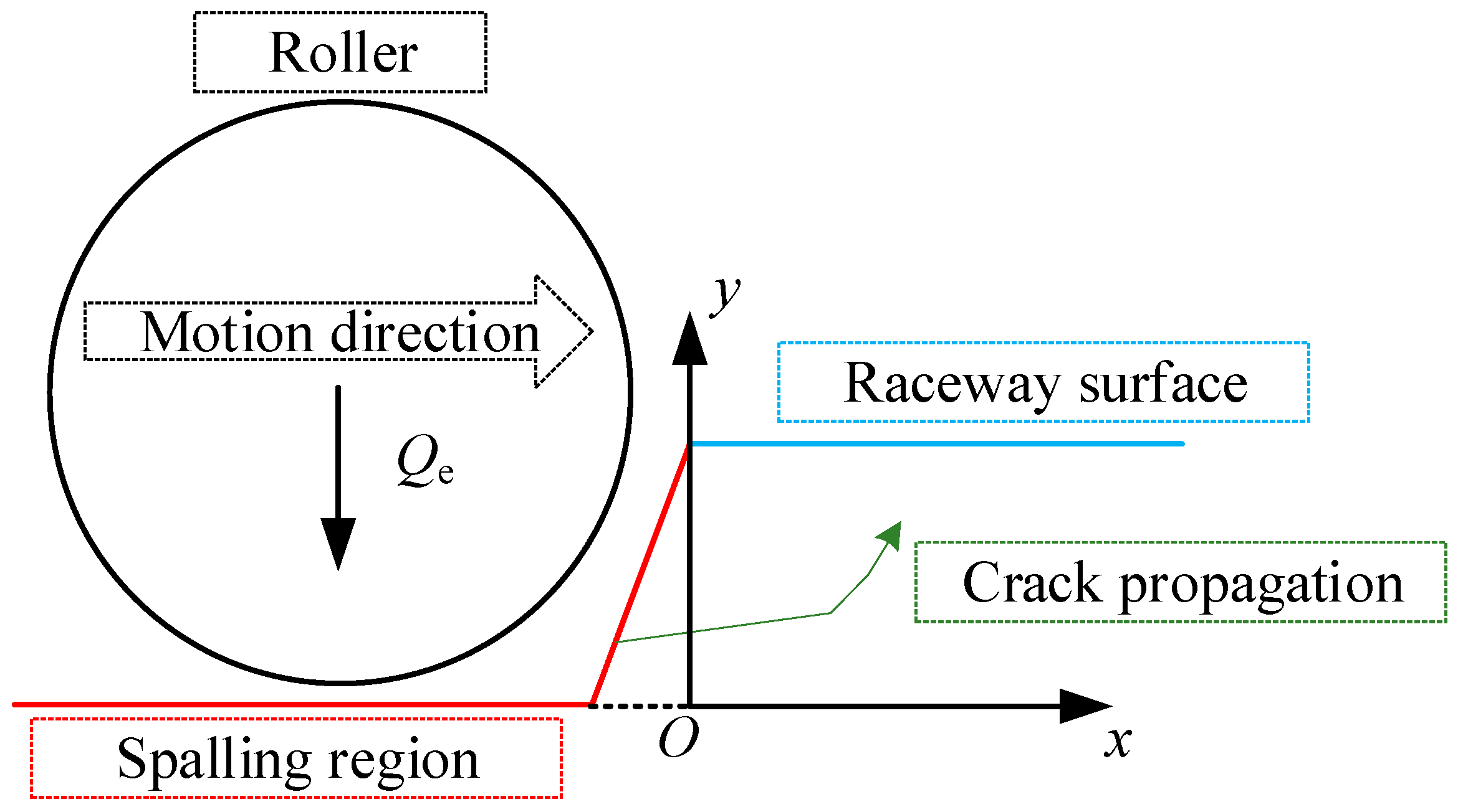
A simplified finite element simulation model of a bearing with a spalling fault is proposed. Based on the combination of spalling defects and the outputs from the EHL model, a 2D rolling contact fatigue crack propagation mechanism model was established. With this model, the variations in SIFs at the crack front under different normal loads were analyzed. As the normal load Q e increased, the variation in the equivalent SIF also increased. The position where the maximum equivalent SIF occurred also advanced.
(2)
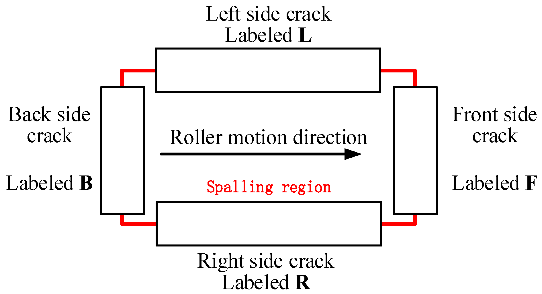
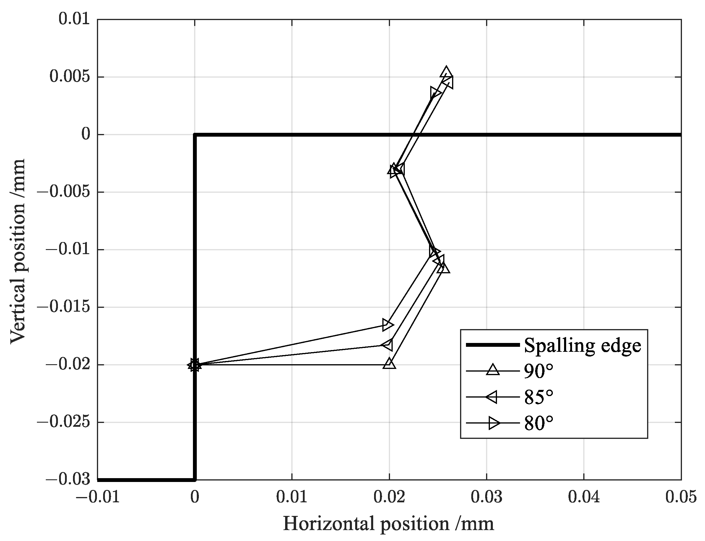
A multi-directional fatigue spalling evolution model for bearing raceway surface spalling has been established. The subsurface cracks around the spalling region were analyzed by changing the relative motion and position relationship between the roller and the spalling defect. The analysis results show that under the working conditions of a radial load F z = 2000   N and an axial load F x = 10,000   N , spalling in 7208AC bearings is more likely to propagate in the direction parallel to the roller movement, particularly in the same direction as the roller movement. Additionally, the propagation behavior of initial cracks at various angles has been investigated. The spalling propagation rate gradually slows down as the initial crack angle increases up to 90°.

Author Contributions

Methodology, Z.D., X.W. and H.W.; Investigation, T.H.; Writing—original draft, Z.D.; Writing—review & editing, H.H.; Funding acquisition, H.H. All authors have read and agreed to the published version of the manuscript.

Funding

This research was supported by the National Science and Technology Major Project under the grant number J2019-IV-0004-0071, which is gratefully acknowledged by the authors.

Institutional Review Board Statement

Not applicable.

Informed Consent Statement

Not applicable.

Data Availability Statement

The original contributions presented in the study are included in the article, further inquiries can be directed to the corresponding author.

Conflicts of Interest

The authors declare no conflict of interest.

References

  1. Vijay, A.; Sadeghi, F. A crystal plasticity and cohesive element model for rolling contact fatigue of bearing steels. Tribol. Int. 2022, 173, 107607. [Google Scholar] [CrossRef]
  2. Zhang, H.; Borghesani, P.; Smith, W.A.; Randall, R.B.; Shahriar, M.R.; Peng, Z. Tracking the natural evolution of bearing spall size using cyclic natural frequency perturbations in vibration signals. Mech. Syst. Signal Process. 2021, 151, 107376. [Google Scholar] [CrossRef]
  3. Zhao, S.; Liang, L.; Xu, G.; Wan, J.; Zhang, W. Quantitative diagnosis of a spall-like fault of a rolling element bearing by empirical mode decomposition and the approximate entropy method. Mech. Syst. Signal Process. 2013, 40, 154–177. [Google Scholar] [CrossRef]
  4. Xia, Z.; Wu, D.; Zhang, X.; Wang, J.; Han, E.H. Rolling contact fatigue failure mechanism of bearing steel on different surface roughness levels under heavy load. Int. J. Fatigue 2024, 179, 108042. [Google Scholar] [CrossRef]
  5. Qiu, L.; Zhao, J.; Pan, X.; Tian, F. Interfacial fatigue spalling behavior of TiN films on high speed steel. Acta Metall. Sin. 2021, 57, 1039–1047. [Google Scholar]
  6. Xu, X.; Li, W.; He, Z.; Hu, H. Adaptive time-domain sliding average method for spall size estimation of roller bearing with skidding. J. Sound Vib. 2023, 567, 117937. [Google Scholar] [CrossRef]
  7. Hou, X.Q.; Zhang, Z.; Liu, C.K.; Tao, C.H. Formation mechanism and influence of white etching area on contact fatigue spalling of M50 bearing steel. Eng. Fail. Anal. 2022, 139, 106273. [Google Scholar] [CrossRef]
  8. Steenbergen, M. Rolling contact fatigue: Spalling versus transverse fracture of rails. Wear 2017, 380–381, 96–105. [Google Scholar] [CrossRef]
  9. Ren, Z.; Li, B.; Zhou, Q. Rolling contact fatigue crack propagation on contact surface and subsurface in mixed mode I+II+III fracture. Wear 2022, 506–507, 204459. [Google Scholar] [CrossRef]
  10. Cen, H.; Lugt, P.M. Replenishment of the EHL contacts in a grease lubricated ball bearing. Tribol. Int. 2020, 146, 106064. [Google Scholar] [CrossRef]
  11. Vijay, A.; Sadeghi, F. Rolling contact fatigue of coupled EHL and anisotropic polycrystalline materials. Tribol. Int. 2022, 169, 107479. [Google Scholar] [CrossRef]
  12. Madar, E.; Galiki, O.; Klein, R.; Bortman, J.; Nickell, J.; Kirsch, M. A new model for bearing spall size estimation based on oil debris. Eng. Fail. Anal. 2022, 134, 106011. [Google Scholar] [CrossRef]
  13. Branch, N.A.; Arakere, N.K.; Forster, N.; Svendsen, V. Critical stresses and strains at the spall edge of a case hardened bearing due to ball impact. Int. J. Fatigue 2013, 47, 268–278. [Google Scholar] [CrossRef]
  14. Bai, Q.; Young, R.P. Numerical Investigation of the Mechanical and Damage Behaviors of Veined Gneiss During True-Triaxial Stress Path Loading by Simulation of In Situ Conditions. Rock Mech. Rock Eng. 2019, 53, 133–151. [Google Scholar] [CrossRef]
  15. Toumi, M.Y.; Murer, S.; Bogard, F.; Bolaers, F. Numerical simulation and experimental comparison of flaw evolution on a bearing raceway: Case of thrust ball bearing. J. Comput. Des. Eng. 2018, 5, 427–434. [Google Scholar] [CrossRef]
  16. Thibault, N.; Bourdon, A.; Rémond, D.; Lecouvreur, D. Dynamic model of a deep grooves ball bearing dedicated to the study of instantaneous angular speed of rotating assemblies. Tribol. Int. 2022, 174, 107753. [Google Scholar] [CrossRef]
  17. Chen, A.; Kurfess, T.R. Signal processing techniques for rolling element bearing spall size estimation. Mech. Syst. Signal Process. 2019, 117, 16–32. [Google Scholar] [CrossRef]
  18. Liu, J.; Xu, Z.; Zhou, L.; Nian, Y.; Shao, Y. A statistical feature investigation of the spalling propagation assessment for a ball bearing. Mech. Mach. Theory 2019, 131, 336–350. [Google Scholar] [CrossRef]
  19. Shi, X.J.; Wang, L.Q.; Mao, Y.Z.; Qin, F.Q. Coupling study on dynamics and TEHL behavior of high-speed and heavy-load angular contact ball bearing with spinning. Tribol. Int. 2015, 88, 76–84. [Google Scholar] [CrossRef]
  20. Deng, Z.; Wei, X.; Li, Y.F.; Huang, H.Z.; Wang, H. Fatigue spalling fault evolution analysis of an angular contact bearing of aeroengines. In Proceedings of the 13th International Conference on Quality, Reliability, Risk, Maintenance, and Safety Engineering, Kunming, China, 26–29 July 2023. [Google Scholar]
  21. Gu, C.; Sheng, X.; Zhang, D.; Meng, X. Thermal mixed elastohydrodynamic lubrication modeling and analysis of the lubricated non-conformal contacts with non-Gaussian surface roughness and coating. Tribol. Int. 2024, 194, 109541. [Google Scholar] [CrossRef]
  22. Bal, H.; Aktürk, N. Vibration modeling of wind turbine shaft as rigid shaft supported by EHL contact ball bearings with overhung disc system. Tribol. Int. 2020, 151, 106481. [Google Scholar] [CrossRef]
  23. Zhao, Y.; Liu, H.C.; Morales-Espejel, G.E.; Venner, C.H. Response of elastic/viscoelastic layers on an elastic half-space in rolling contacts: Towards a new modeling approach for elastohydrodynamic lubrication. Tribol. Int. 2023, 186, 108545. [Google Scholar] [CrossRef]
  24. Neu, M.; Zaiat, A.; Harder, A.; Kirchner, E.; Hussong, J. Multi-physics modeling of roller bearing raceway imperfections compared to electric measurements of an EHL point contact. Tribol. Int. 2022, 173, 107668. [Google Scholar] [CrossRef]
  25. Chen, Y.; Jin, X.; Yue, Y.; Wang, S.; Han, H.; Wen, M.; Wang, Q.; Cheng, P. Investigation on 3D fatigue crack propagation in pitch bearing raceway of offshore wind turbines. Ocean Eng. 2023, 269, 113524. [Google Scholar] [CrossRef]
  26. Tavares, S.M.O.; de Castro, P.M.S.T. Equivalent Stress Intensity Factor: The Consequences of the Lack of a Unique Definition. Appl. Sci. 2023, 13, 4820. [Google Scholar] [CrossRef]
  27. Richard, H.A.; Schramm, B.; Schirmeisen, N.H. Cracks on mixed mode loading–theories, experiments, simulations. Int. J. Fatigue 2014, 62, 93–103. [Google Scholar] [CrossRef]
Figure 1. Propagation of a spalling crack on the subsurface of a raceway.
Applsci 14 05072 g001
Figure 2. Flowchart of multi-direction bearing spalling expansion analysis.
Applsci 14 05072 g002
Figure 3. Finite element model of contact stress simulation at spalling. The dotted line in the figure is the line between the roller and its center of rotation.
Applsci 14 05072 g003
Figure 4. Spalling region contact FEA model. In the figure, the outline of the roller appears as a polygon.
Applsci 14 05072 g004
Figure 5. Size parameters and constraints of the model. In the figure, the red line represents the position as a completely fixed constraint.
Applsci 14 05072 g005
Figure 6. Mesh division of spalling region contact FEA model. In the figure, the polygonal lines are the outer outline of the roller before grid division. The cyan lines are the outer outline of the roller after grid division. The orange dots represent selected nodes for this grid division.
Applsci 14 05072 g006
Figure 7. Simulation schematic diagram of spalling area.
Applsci 14 05072 g007
Figure 8. Contact force of the outer ring.
Applsci 14 05072 g008
Figure 9. Image of 7208AC bearing.
Applsci 14 05072 g009
Figure 10. Von Mises stress at the edge of the spalling region.
Applsci 14 05072 g010
Figure 11. Four-direction crack locations.
Applsci 14 05072 g011
Figure 12. Flowchart of crack propagation simulation.
Applsci 14 05072 g012
Figure 13. SIF variation map of the spalling region.
Applsci 14 05072 g013
Figure 14. Schematic diagram of a symmetric crack with left–right symmetry.
Applsci 14 05072 g014
Figure 15. Two-dimensional spalling crack propagation path under 3 different initial angles.
Applsci 14 05072 g015
Table 1. Geometry and material parameters of 7208AC bearing.
SymbolValue
Internal   diameter   of   the   bearing   d /mm40
External   diameter   D /mm80
Number   of   rollers   z 12
Roller   diameter   D w /mm11.1125
Radial clearance/mm0.156
Pitch   diameter   D m /mm60
Nominal   contact   angle   of   balls   and   outer   race   α 25
Rotational speed/rpm7000
Radial   load   F z /N2000
Axial   load   F x /N10,000
Modulus   of   elasticity   E /MPa214,500
Poisson s   ratio   μ 0.28
Table 2. Crack propagation results for cracks labeled F.
Iteration NumberRequired Time
/s
Crack Deflection Angle
φ 0
Crack Propagation Rate
v 0 /mm·s−1
1714.751755.92264.7856 × 10−8
22872.495964.18171.1908 × 10−8
31219.1836−61.28242.8056 × 10−8
Table 3. Crack propagation results for cracks labeled B.
Iteration NumberRequired Time
/s
Crack Deflection Angle
φ 0
Crack Propagation Rate
v 0 /mm·s−1
1564.320456.26856.0613 × 10−8
23603.263664.32819.4928 × 10−9
3709.7066−63.26604.8196 × 10−8
Table 4. Crack propagation results for cracks labeled L and R.
Iteration NumberRequired Time
/s
Crack Deflection Angle
φ 0
Crack Propagation Rate
v 0 /mm·s−1
11664.420555.41682.0551 × 10−8
213,772.5942264.62092.4836 × 10−9
3955.9112−61.28873.5783 × 10−8
Table 5. Crack propagation at 3 different initial angles.
Initial
Angle
Number
of
Updating
Deflection Angle
Propagation Velocity
/mm·cycle−1
Required Time
/h
80153.03684.8496 × 10−7 8.2697
267.02841.8805 × 10−7
3−61.08364.9677 × 10−8
85153.98531.7416× 10−725.02065
262.87051.8382 × 10−8
3−60.56475.2528 × 10−8
90156.26856.0613 × 10−854.8104
264.32819.4928 × 10−9
3−63.26604.8196 × 10−8
Disclaimer/Publisher’s Note: The statements, opinions and data contained in all publications are solely those of the individual author(s) and contributor(s) and not of MDPI and/or the editor(s). MDPI and/or the editor(s) disclaim responsibility for any injury to people or property resulting from any ideas, methods, instructions or products referred to in the content.

