Effects of Vertical Motion on Uplift of Underground Structure Induced by Soil Liquefaction
Abstract
:Featured Application
Abstract
1. Introduction
2. PM4Sand Model
- The PM4Sand model adopts the bounding, dilatancy, and critical state surfaces of the DM model but removes the Lode angle dependency proposed in the DM model to simplify the model calculation. The surfaces of the DM model in p–q space (p is the mean effective stress and q is the deviatoric stress) are shown in Figure 1.
- 2.
- The DM model incorporates the critical state behavior into the bounding and dilatancy surfaces by using the state parameter (the difference between the void ratio at the critical state and the current void ratio with the same mean effective stress). The PM4Sand model adopts the same concept but incorporates the relative state parameter index (the difference between the relative density at the critical state and the current relative density with the same mean effective stress). The critical state compatible bounding and dilatancy surfaces evolve when soil is sheared and will coincide with the critical state surface when the soil reaches the critical state. This concept allows the constitutive model to control the evolution of the peak friction angle according to the relative state of the soil during shearing.
- 3.
- The DM model includes the initial back–stress ratio (=q/p in p–q space) in the computation of the plastic modulus to account for the decrease in the plastic modulus with an increase in the back–stress ratio during loading. In the PM4Sand model, the initial back-stress ratio and the previous initial back-stress ratio are both tracked. In this way, the overestimated stiffening of the stress–strain response during the small unloading and reloading cycles in DM model can be improved.
- 4.
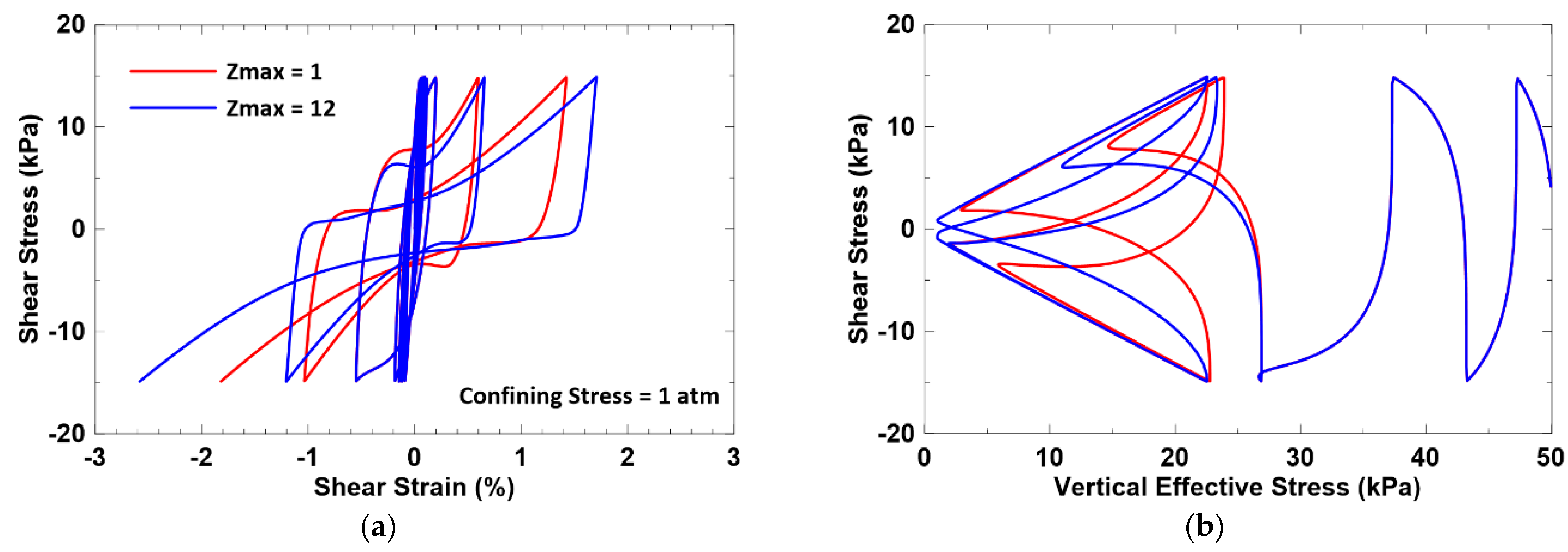
- The DM model uses the fabric–dilatancy tensor (z) to account for the build-up of porewater pressure upon the reversal of the stress increment following a dilative tendency response (the butterfly loop of the stress path) when the soil reaches soil liquefaction (at very low effective pressure). In the PM4Sand model, the total evolution of the fabric–dilatancy tensor is also tracked to control the rate of evolution for the fabric–dilatancy tensor and the plastic modulus. Thus, the undrained cyclic stress–strain response of the PM4Sand model can capture the progressively accumulated shear strains observed in the cyclic simple shear test which many plasticity models are not able to model. The responses of PM4Sand with two maximum fabric–dilatancy tensor values (zmax = 1 and 12) are plotted in Figure 2. Figure 2a shows the accumulated shear strain behavior during cyclic loading, and Figure 2b demonstrates that, through an adjustment of the value of zmax, the PM4Sand model can simulate the shape of a butterfly loop.
- 5.
- As the energy of the input motion is strongly related to the magnitude of the uplift [8], it is important to properly model the hysteretic response of the soil. The plastic modulus of the PM4Sand model is formulated to provide improved relationships of shear modulus reduction and equivalent damping ratio during drained cyclic loading. In addition, the elastic modulus of the PM4Sand model degrades with the total evolution of the fabric–dilatancy tensor to account for the progressive destruction with increasing plastic shear strains. This approach helps the PM4Sand model capture the hysteretic loop better than many plasticity models.
- 6.
- The key input parameters of the PM4Sand model (version 3.1) are listed and introduced in Table 1.
3. Numerical Model
4. Earthquake Motions
5. Results and Discussions
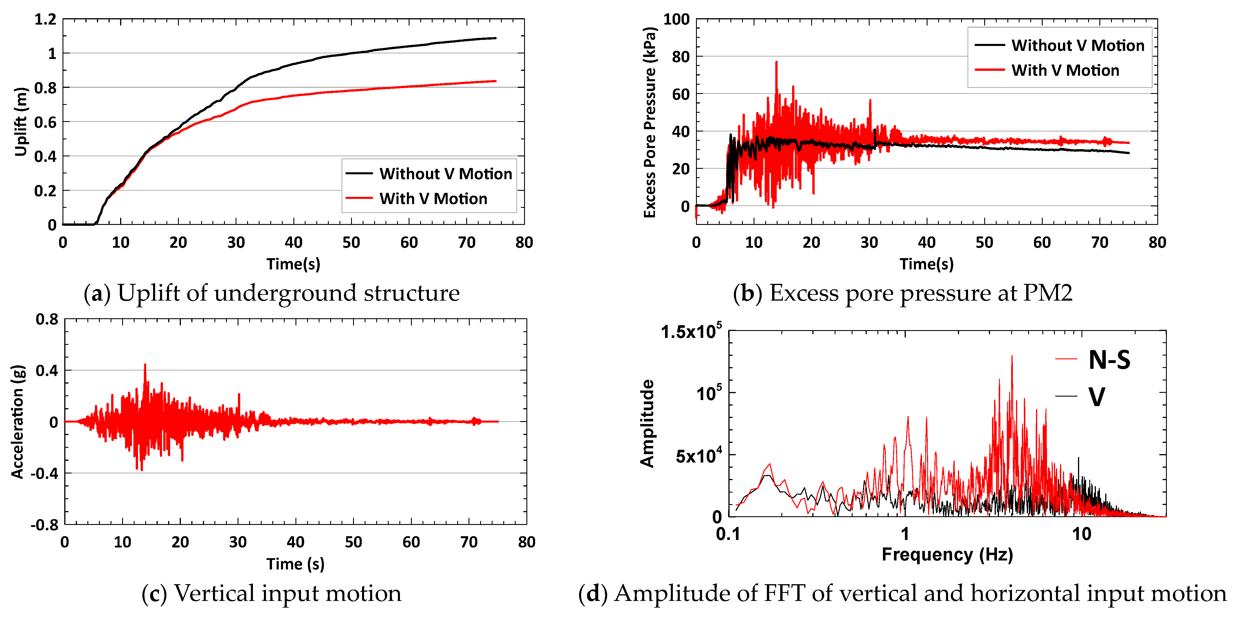
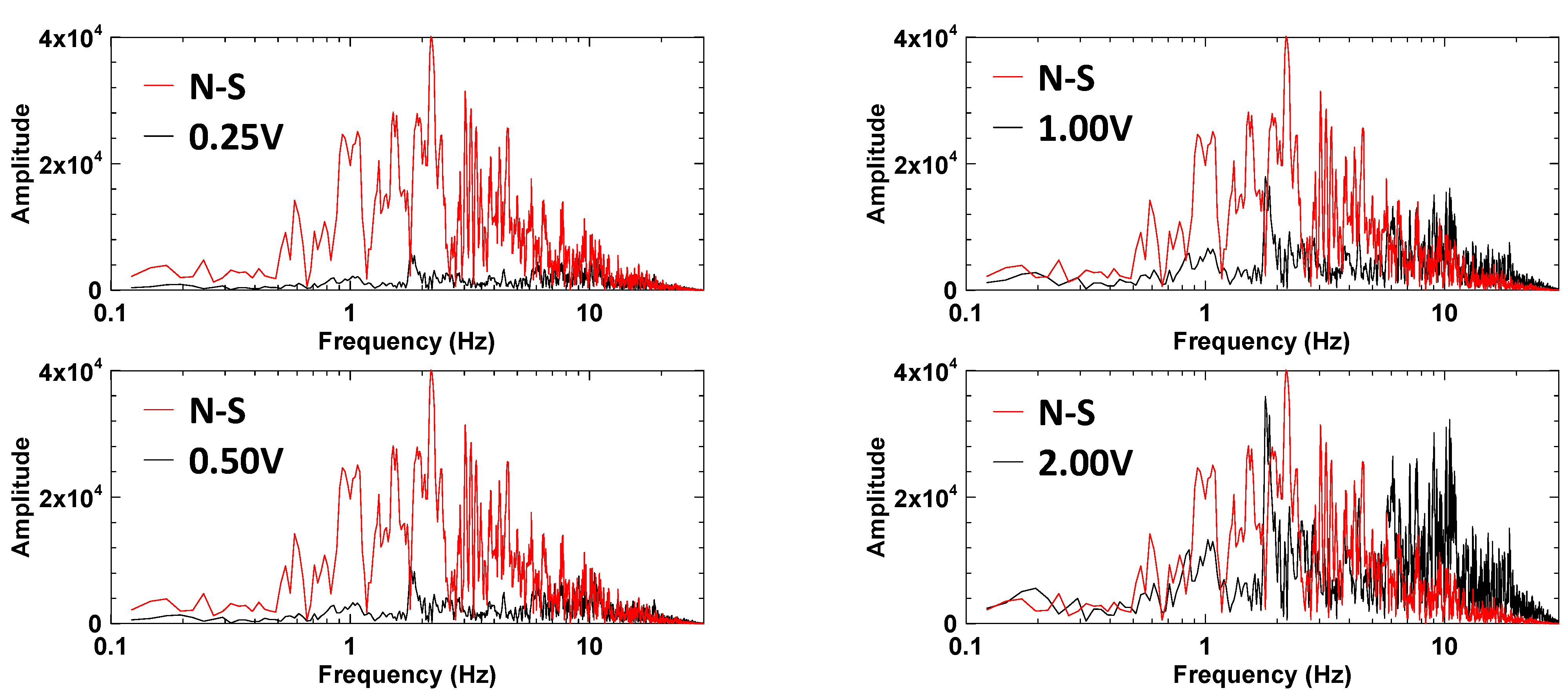
- A comparison of all TCU017−N cases shows that the decrease in the uplift is caused by the wave in the frequency range of 9–14 Hz in the vertical motion. When the amplitude of FFT in a frequency range of 9–14 Hz in the vertical motion is no longer higher than the amplitude of FFT at the same frequency range in the horizontal motion, the uplift ratio of TCU071−N cases increases from 0.77 in the 1.00 V case to 1.00 in the 0.33 V case.
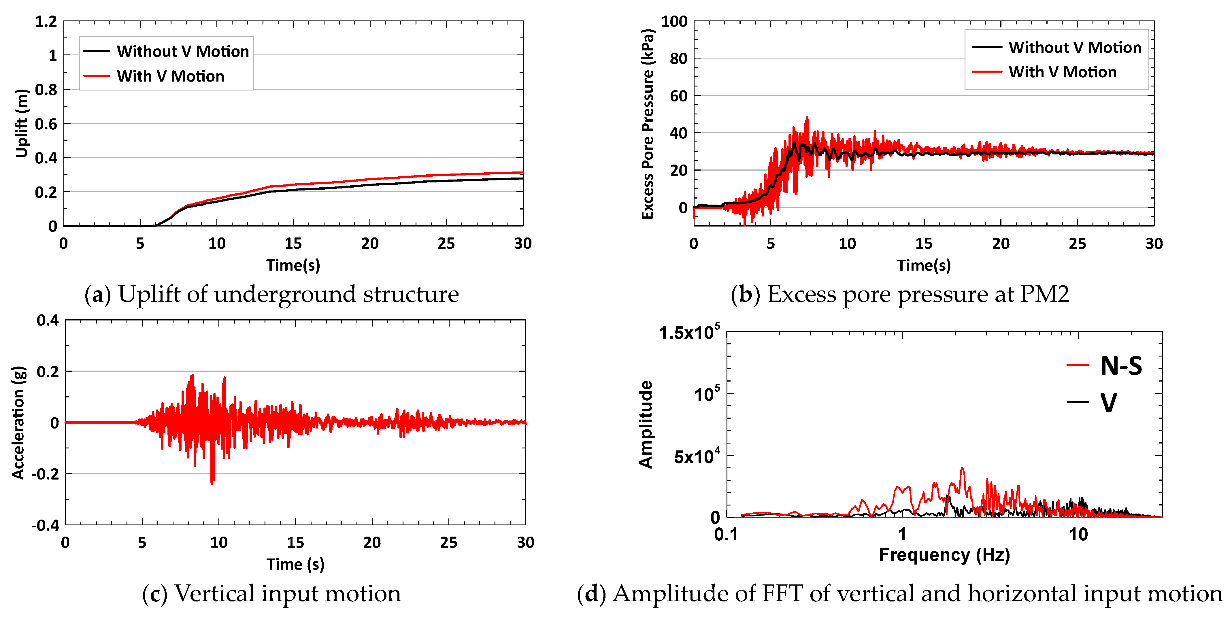
- A comparison of the 2.00 V case of TCU071−N and all HWA027−N cases shows that the increase in the uplift is caused by the wave in the frequency range of 1–2 Hz (1.2 Hz for TCU071−N and 1.8 Hz for HWA027−N). When the amplitude of FFT at a frequency range of 1–2 Hz in the vertical motion is no longer higher than the amplitude of FFT in the same frequency range in the horizontal motion (0.33 V/0.66 V/1.00 V cases of TCU071−N and 0.25 V case of HWA027−N), the uplift ratio decreases.
- The predominant period, T, of the soil column in the centrifuge test is calculated as follows:where H is the height of the soil column in the centrifuge test (which is 10 m), and Vs is the shear wave velocity of the soil (as listed in Table 2). In this study, for Dr = 30% to 70%, T ranges from 0.31 s (4 × 10 m/130 m/s) to 0.2 s (4 × 10 m/200 m/s). The natural frequency of the soil column ranges from 3.22 Hz to 5 Hz. When soil is liquefied, the shear wave velocity of soil will decrease depending on the severity of the liquefaction, causing a decrease in the natural frequency of the soil column. Therefore, a possible explanation for the wave in the frequency range of 1–2 Hz increasing the uplift might be that this wave frequency range is close to the natural frequency of the liquefied soil. When the wave frequency range (9–14 Hz) is much higher than the natural frequency (3.22–5 Hz) of the soil column, these high frequency waves cause transient responses in the excess pore pressure and lower the uplift.T = 4 × H/Vs,
6. Conclusions
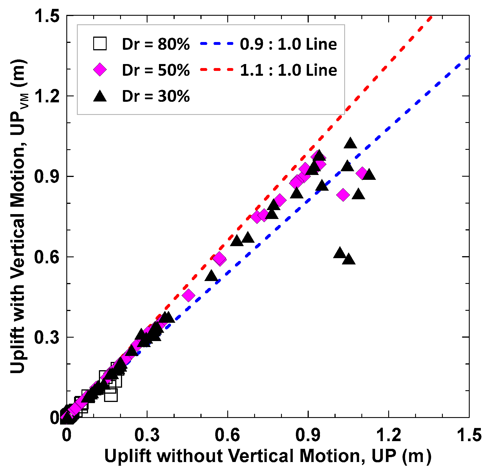
- Most simulation cases with vertical input motion have uplift ratios between 0.9 and 1.1 (a 10% difference in the uplift). Exceptions are cases where the vertical motion lowers the uplift by 20% to 50%. These exceptions occur in cases with higher peak acceleration, Arias intensity, and CAV. These cases come from the Chi−Chi earthquake event, which possessed a higher earthquake magnitude.
- If the amplitude of FFT of the vertical motion is higher than the amplitude of FFT of the horizontal motion at a frequency range higher (twice as high) than the natural frequency of soil, then, the vertical motion decreases the uplift. Conversely, if the amplitude of FFT of the vertical motion is higher than the amplitude of FFT of the horizontal motion in a frequency range close to the natural frequency of soil, then the vertical motion increases the uplift.
Funding
Institutional Review Board Statement
Informed Consent Statement
Data Availability Statement
Acknowledgments
Conflicts of Interest
References
- Sasaki, T.; Tamura, K. Prediction of liquefaction-induced uplift displacement of underground structures. In Proceedings of the 36th Joint Meeting US-Japan Panel on Wind and Seismic Effects, Gaithersburg, MD, USA, 17–22 May 2004; Volume 36, pp. 191–198. [Google Scholar]
- Liu, H.; Song, E. Seismic response of large underground structures in liquefiable soils subjected to horizontal and vertical earthquake excitations. Comput. Geotech. 2005, 32, 223–244. [Google Scholar] [CrossRef]
- Chou, J.C. Centrifuge Modeling of the BART Transbay Tube and Numerical Simulation of Tunnels in Liquefying Ground. Ph.D. Dissertation, University of California, Davis, CA, USA, 2010. [Google Scholar]
- Madabhushi, S.S.C.; Madabhushi, S.P.G. Finite element analysis of floatation of rectangular tunnels following earthquake induced liquefaction. Indian Geotech. J. 2015, 45, 233–242. [Google Scholar] [CrossRef]
- Han, Y.; Liu, H. Failure of circular tunnel in saturated soil subjected to internal blast loading. Geomech. Eng. 2016, 11, 421–438. [Google Scholar] [CrossRef]
- Bao, X.; Xia, Z.; Ye, G.; Fu, Y.; Su, D. Numerical analysis on the seismic behavior of a large metro subway tunnel in liquefiable ground. Tunn. Undergr. Space Technol. 2017, 66, 91–106. [Google Scholar] [CrossRef]
- Castiglia, M.; de Magistris, F.S.; Napolitano, A. Stability of onshore pipelines in liquefied soils: Overview of computational methods. Geomech. Eng. 2018, 14, 355–366. [Google Scholar] [CrossRef]
- Chou, J.C.; Lin, D.G. Incorporating ground motion effects into Sasaki and Tamura prediction equations of liquefaction-induced uplift of underground structures. Geomech. Eng. 2020, 22, 25–33. [Google Scholar] [CrossRef]
- Huang, K.H. Effects of Vertical Motion on Liquefaction-Induced Uplift of Underground Structure. Master’s Thesis, National Chung Hsing University, Taichung, China, 2021. (In Chinese). [Google Scholar]
- Do, T.M.; Do, A.N.; Vo, H.T. Numerical analysis of the tunnel uplift behavior subjected to seismic loading. J. Min. Earth Sci. 2022, 63, 1–9. [Google Scholar]
- Wang, R.; Zhu, T.; Yu, J.K.; Zhang, J.M. Influence of vertical ground motion on the seismic response of underground structures and underground-aboveground structure systems in liquefiable ground. Tunn. Undergr. Space Technol. 2022, 122, 104351. [Google Scholar] [CrossRef]
- Seyedi, M. An Empirical Function to Predict the Liquefaction-Induced Uplift of Circular Tunnels. Transp. Infrastruct. Geotech. 2024, 1–26. [Google Scholar] [CrossRef]
- Boulanger, R.W. A Sand Plasticity Model for Earthquake Engineering Applications; Center for Geotechnical Modeling: Davis, CA, USA, 2010. [Google Scholar]
- Boulanger, R.W.; Ziotopoulou, K. Formulation of a sand plasticity plane-strain model for earthquake engineering applications. J. Soil Dyn. Earthq. Eng. 2013, 53, 254–267. [Google Scholar] [CrossRef]
- Ziotopoulou, K.; Boulanger, R.W. Calibration and implementation of a sand plasticity plane-strain model for earthquake engineering applications. J. Soil Dyn. Earthq. Eng. 2013, 53, 268–280. [Google Scholar] [CrossRef]
- Ziotopoulou, K.; Boulanger, R.W. Plasticity modeling of liquefaction effects under sloping ground and irregular cyclic loading conditions. Soil Dyn. Earthq. Eng. 2016, 84, 269–283. [Google Scholar] [CrossRef]
- Boulanger, R.W.; Ziotopoulou, K. PM4Sand (Version 3.1): A Sand Plasticity Model for Earthquake Engineering Applications; Department of Civil and Environmental Engineering, University of California: Davis, CA, USA, 2017. [Google Scholar]
- Manzari, M.T.; Dafalias, Y.F. A critical state two-surface plasticity model for sands. Géotechnique 1997, 47, 255–272. [Google Scholar] [CrossRef]
- Dafalias, Y.F.; Manzari, M.T. Simple plasticity sand model accounting for fabric change effects. J. Eng. Mech. 2004, 130, 622–634. [Google Scholar] [CrossRef]
- FLAC Version 8.0, Itasca Consulting Group Inc.: Minneapolis, MN, USA, 2016.
- Andrus, R.D.; Stokoe, K.H. Liquefaction resistance of soils from shear-wave velocity. J. Geotech. Geoenviron. Eng. ASCE 2000, 126, 1015–1025. [Google Scholar] [CrossRef]
- Itasca UDM Web Site. Available online: https://www.itascacg.com/software/udm-library/ubcsand (accessed on 1 October 2023).






| Input Parameter | Description |
|---|---|
| Shear modulus coefficient (Go) | Go is used to estimate the small strain shear modulus. |
| Contraction rate parameter (hpo) | hpo controls the contraction rate of the plastic volumetric strain related to the cyclic resistance ratio (CRR) of soil. |
| Ratio of plastic modulus and elastic modulus (ho) | ho relates to relative density (Dr) and controls the ratio of plastic modulus to elastic modulus. Model default value provides reasonable modulus reduction and damping curves. |
| Material constant of bounding stress ratio (nb) | nb controls the bounding surface (dilatancy), which is related to the peak effective friction angles. |
| Material constant of dilatancy stress ratio (nd) | nd controls the phase transformation where the contraction behavior transitions to the dilation behavior. |
| Maximum value of fabric–dilatancy tensor (zmax) | zmax is the maximum value of fabric–dilatancy tensor. |
| Material constant of dilatancy (Ado) | zmax and Ado are used to control the buildup value of the porewater pressure upon reversal of stress increment following a dilative tendency response. |
| Centrifuge Test Case No | 97−06 | 98−01 | 97−02 |
|---|---|---|---|
| Unit weight of underground structure | 0.8 t/m3 | 0.8 t/m3 | 0.8 t/m3 |
| Relative density of Toyoura sand (Dr) | 30% | 50% | 80% |
| Equivalent SPT N value, (N1)60 1 | 4 | 12 | 30 |
| Shear wave velocity (Vs) 2 | 130 m/s | 165 m/s | 200 m/s |
| Input motion | Sinusoidal wave (20 cycles with 1.2 Hz) | ||
| Uplift of centrifuge test | 1.24 m | 1.09 m | 0.23 m |
| Centrifuge Test Case No | 97−06 | 98−01 | 97−02 |
|---|---|---|---|
| Shear modulus coefficient (Go) 1 | 426 | 636 | 952 |
| Contraction rate parameter (hpo) 2 | 0.35 | 0.10 | 1.35 |
| Ratio of plastic modulus and elastic modulus (ho) 2 | 0.15 | 0.15 | 0.15 |
| Material constant of bounding stress ratio (nb) 3 | 0.65 | 0.13 | 0.28 |
| Material constant of dilatancy stress ratio (nd) 1 | 0.10 | 0.10 | 0.10 |
| Maximum value of fabric–dilatancy tensor (zmax) 1 | 0.78 | 2.89 | 17.70 |
| Material constant of dilatancy (Ado) 1 | 1.30 | 1.20 | 1.20 |
| Uplift of numerical simulation | 1.20 m | 1.04 m | 0.26 m |
| Event (Date) | Epicenter (Latitude/Longitude) | Mw | Sets of Motions | Epicenter Distance |
|---|---|---|---|---|
| Chi−Chi earthquake (1999/09/21) | 23.85 N/120.82 E | 7.6 | 16 | 5–37 km |
| Chiayi earthquake (1999/10/22) | 23.51 N/120.40 E | 5.9 | 8 | 5–33 km |
| Chiashien earthquake (2010/03/04) | 22.97 N/120.71 E | 5.8 | 6 | 18–37 km |
| Tainan earthquake (2016/02/06) | 22.92 N/120.54 E | 6.5 | 10 | 2–37 km |
| Hualian earthquake (2018/02/06) | 24.10 N/121.73 E | 6.2 | 8 | 8–39 km |
| Dr = 30% Case | Uplift Ratio (UPVM/UP) (m) | Peak Input Acc. Ratio (V/N−S) 1 (g) | Ia Ratio (V/N−S) (m/s) | CAV Ratio (V/N−S) (g−s) |
|---|---|---|---|---|
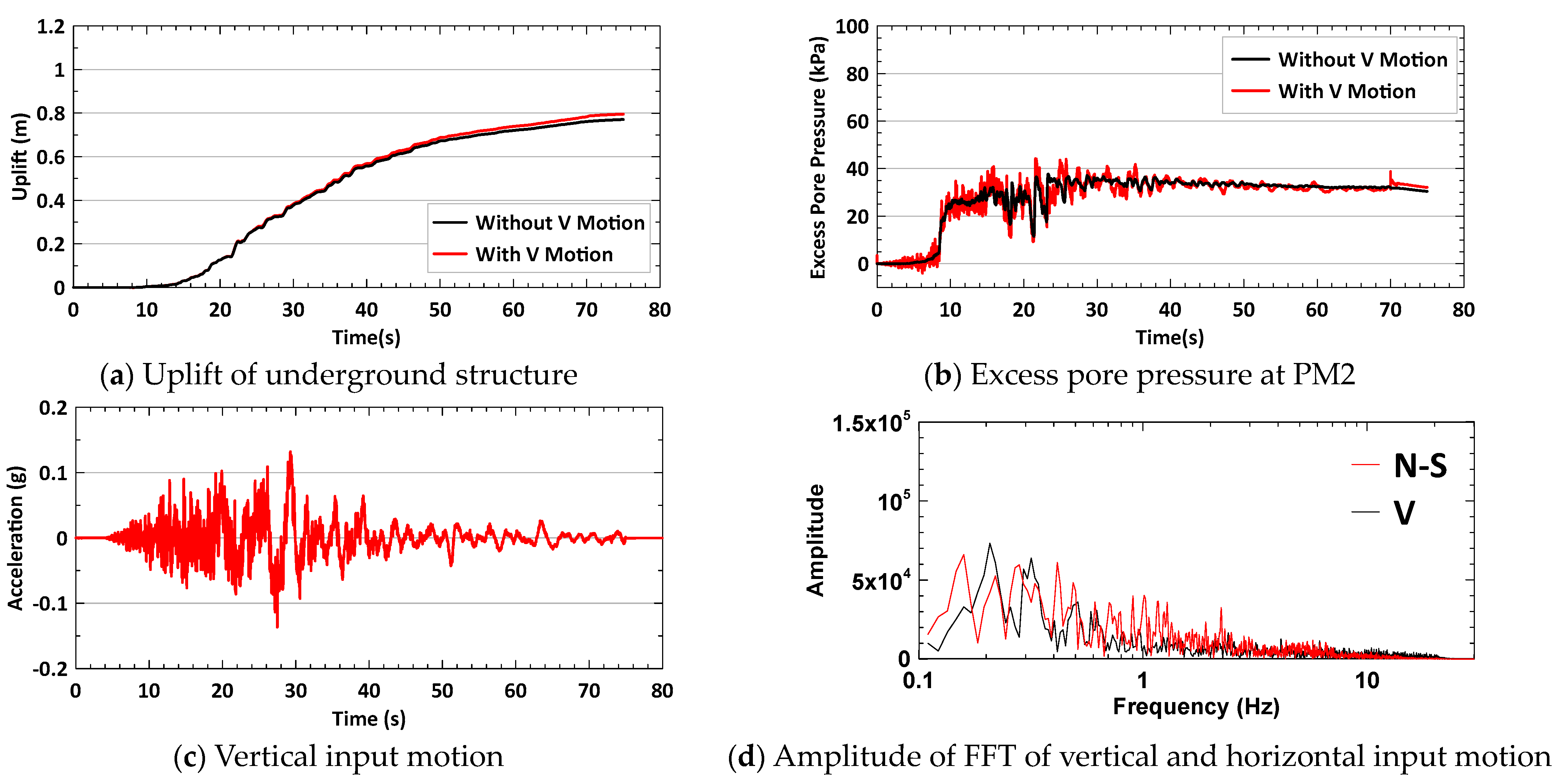
| TCU071−N (Chi−Chi earthquake) | 0.77 (0.836/1.087) | 0.62 (0.44/0.71) | 0.21 (2.49/11.76) | 0.47 (1.80/3.87) |
| TCU063−N (Chi−Chi earthquake) | 1.04 (0.796/0.771) | 0.93 (0.13/0.14) | 0.63 (0.75/1.20) | 0.81 (1.21/1.49) |
| HWA027−N (Hualian earthquake) | 1.13 (0.313/0.278) | 0.69 (0.24/0.35) | 0.30 (0.43/1.41) | 0.58 (0.52/0.90) |
| TCU071−N | HWA027−N | ||||
|---|---|---|---|---|---|
| Case | Uplift Ratio | Vertical PIA 1 | Case | Uplift Ratio | Vertical PIA |
| 0.33 V | 1.00 | 0.16 g | 0.25 V | 1.04 | 0.06 g |
| 0.67 V | 0.76 | 0.27 g | 0.50 V | 1.10 | 0.12 g |
| 1.00 V 2 | 0.77 | 0.44 g | 1.00 V | 1.13 | 0.24 g |
| 2.00 V 2 | 1.06 | 0.86 g | 2.00 V | 1.10 | 0.46 g |
Disclaimer/Publisher’s Note: The statements, opinions and data contained in all publications are solely those of the individual author(s) and contributor(s) and not of MDPI and/or the editor(s). MDPI and/or the editor(s) disclaim responsibility for any injury to people or property resulting from any ideas, methods, instructions or products referred to in the content. |
© 2024 by the author. Licensee MDPI, Basel, Switzerland. This article is an open access article distributed under the terms and conditions of the Creative Commons Attribution (CC BY) license (https://creativecommons.org/licenses/by/4.0/).
Share and Cite
Chou, J.-C. Effects of Vertical Motion on Uplift of Underground Structure Induced by Soil Liquefaction. Appl. Sci. 2024, 14, 5098. https://doi.org/10.3390/app14125098
Chou J-C. Effects of Vertical Motion on Uplift of Underground Structure Induced by Soil Liquefaction. Applied Sciences. 2024; 14(12):5098. https://doi.org/10.3390/app14125098
Chicago/Turabian StyleChou, Jui-Ching. 2024. "Effects of Vertical Motion on Uplift of Underground Structure Induced by Soil Liquefaction" Applied Sciences 14, no. 12: 5098. https://doi.org/10.3390/app14125098
APA StyleChou, J.-C. (2024). Effects of Vertical Motion on Uplift of Underground Structure Induced by Soil Liquefaction. Applied Sciences, 14(12), 5098. https://doi.org/10.3390/app14125098


