Article

Simulation Analysis of Cyclone Separator for Separation of Cenospheres

1
College of Energy and Mechanical Engineering, Shanghai University of Electric Power, Shanghai 200090, China
2
National Metal and Materials Technology Center (MTEC), National Science and Technology Development Agency (NSTDA), 111 Thailand Science Park, Phahonyothin Road, Khlong Nueng, Khlong Luang, Pathum Thani 12120, Thailand
*
Author to whom correspondence should be addressed.
Appl. Sci. 2024, 14(12), 5132; https://doi.org/10.3390/app14125132
Submission received: 14 May 2024 / Revised: 31 May 2024 / Accepted: 5 June 2024 / Published: 13 June 2024

Abstract

:
The separation of cenospheres is an important method for fly ash recycling, and there is no efficient and less polluting method available for separating cenospheres. This paper proposes the dry separation of cenospheres using a cyclone separator, which utilizes the small density of cenospheres as a feature to separate them. The corresponding numerical simulations of the cyclone separator model used to separate the cenospheres were carried out by a CFD analysis, after which the size of the radius of the upper discharge opening and the height of the sloping wall of the cyclone separator were analyzed by simulation; the effect of the incident velocity on the Newton’s efficiency of the separation of the cenospheres was also analyzed. The simulation results indicate that the Newton’s efficiency can reach 0.55 when the radius of the upper feed port is 90 mm, the height of the inclined wall is 400 mm, and the incident speed is 2.5 m/s.

1. Introduction

Coal is widely used to generate electricity around the world, with about 41% of global electricity being generated by coal-fired thermal power plants, which is expected to increase to about 44% by 2030 [1]. In 2020, the U.S. generated 76 million tons of coal combustion byproducts, 44.5% of which were recycled, with the remainder being transported to landfills and ash ponds for disposal [2]. The largest share of coal combustion by-products is represented by fly ash, which is produced worldwide at a rate of about 750 million tons per year and growing [3,4]. Previously, due to the low cost of land and the immaturity of fly ash recycling technology, fly ash was simply disposed of in landfills [5,6], which put enormous pressure on the environment; nowadays, due to the rising cost of land, the cost of landfills of fly ash has also increased, and with the increase in awareness of environmental protection, recycling fly ash is receiving more and more attention, meaning that many value-added applications have been proposed [7,8,9,10]. Recycling fly ash not only reduces landfill costs and land occupation but also alleviates the ecological pollution caused by fly ash and creates considerable economic benefits. The environmental impact of fly ash can be minimized by physically separating it and using it as a raw material for a variety of value-added products [11].
Cenospheres are hollow spherical particles that are one of the important value-added materials in fly ash. The unique properties of cenospheres include being lightweight and having a good fill factor, enhanced insulation, improved flow characteristics, low water absorption, high compressive strength, chemical inertness, and heat resistance, making them suitable for a wide range of industrial applications [12,13,14]. Cenospheres are spherical with a small surface area to volume ratio, requiring less resin, binder, and water to wet the surface. This property makes them a desired filler for polymers and various polymer composites such as polyurethane composites; polyester composites; functional gradient materials; synthetic polymer foams; and high-impact strength nylon composites. In addition, the electrical properties of polymers can be altered from insulating to conductive materials by plating copper on the cenospheres and incorporating them into organic polymers [15,16,17,18]. The outer shells of cenospheres mainly consist of an aluminum silicate phase, a material widely used in the manufacture of high-temperature aluminum syntactic foams because of its excellent thermal stability. This foam material not only has high energy absorption and damping properties but also shows its superiority in the manufacture of automotive brake rotors and differential covers. In addition, aluminum composite foams exhibit more significant electromagnetic shielding than conventional base alloys. Nickel-coated cenospheres also show potential for electromagnetic shielding and microwave absorption, a discovery that provides a new direction for research in the field of materials science [14,19,20]. As a mullite-rich advanced material, cenospheres show promise for a wide range of applications in areas as diverse as diesel engine components, refractory materials, heat exchangers, glass remelting in industrial furnaces, steel soaking, and aluminum alloy recycling. In addition, cenosphere ceramic foam coatings are considered to have significant development potential due to their high thermal stability, low coefficient of thermal expansion, and excellent resistance to creep, crack propagation, and thermal shock in extreme oxidizing and corrosive environments. These properties make them particularly important in modern industrial applications, especially in environments where a high degree of material reliability and durability is required [8,21]. In construction materials science, cenospheres are recognized as an innovative lightweight additive suitable for the preparation of low-density, low-water release cementitious composites. The spherical and hollow structure, chemical composition, and mechanical and energy dissipation properties of these cenospheres allow them to be fused with conventional cements to form lightweight workable materials with closed pores, which are particularly suitable for bridge decks, sidewalks, and highways where durability is required. The application of porous cenospheres as an internal curing agent is able to absorb and retain up to 180 wt% of water, which is slowly released in the silicate cementitious matrix, effectively controlling autogenous shrinkage. In addition, cenospheres can be used in noise barriers and asphalt concrete matrices to provide excellent sound damping and freeze–thaw resistance. Their lightweight properties also help to simplify the installation process, thereby maximizing cost-effectiveness. These properties make cenospheres an important application and potential development for modern building technology [22,23].
The separation of hollow beads has two methods: dry separation and wet separation. The most commonly used method for industrial separation of hollow beads from fly ash is wet separation, where floating particles in the ash ponds or lagoons are separated into hollow beads; the density of the hollow beads collected by this method is less than 1.0 g/cc [24,25,26,27]. Most of the separations described in the present literature are achieved by wet separation processes, which are generally carried out using water or other solutions as the medium for separation, and the efficiency of the wet separation depends on a number of factors, such as the density difference and buoyancy between the solid particles and selected solution; the concentration of the feed particles; the smoothness of the particle surfaces; and the recycling of the solution [1]. Sorachon Yoriya utilized acetone solution for the wet separation of cenospheres and analyzed the effect of different concentrations of acetone solution on the separation efficiency, recovery, and quality produced by the cenospheres microspheres [28]. To some extent, wet separation may pollute the environment, as the current technology of wet separation consumes large amounts of water and leads to water pollution and soil contamination due to the leaching of toxic substances from fly ash, especially in countries with limited living space [29]. A further disadvantage may be the accumulation of fly ash particles on the buoyant surface, which restricts the sinking of the solid particles in the C and F fly ash, leading to an increase in impurities in the cenospheres product. In addition, Ca(OH)2 crystallization can form on the surface of the hollow beads when the calcium content of the fly ash is high. These crystals harden during the drying process of the cenospheres, thus limiting their further application [2]. The wet separation process has many unavoidable shortcomings, so the study of dry separation is particularly important. Dry separation can keep the chemical composition of the particles unchanged and avoid water pollution and energy consumption caused by drying, and the required technical equipment occupies less space compared with wet separation. One of the applied technologies is the air classifier, which is a unit operation technology that utilizes the geometric or hydrodynamic/aerodynamic equivalent diameter of the particles as well as density differences for solid particle separation. The technology consists of five classifier types: gravity, cascade, fluidized bed, inertial, and centrifugal. The classifiers designed for micron-sized particle separation are the inertial and centrifugal classifiers, while the other types are suitable for millimeter-sized particle separation. The separation process is based on the particles being suspended in a gas stream and subjected to gravity and having drag forces acting in opposite directions. When the terminal settling velocity of the particles exceeds the airflow velocity, the heavier particles will sink against the flow; conversely, the lighter particles with terminal settling velocities lower than the airflow velocity will rise with the airflow to the top of the classifier [30,31].
A cyclone separator is a device that utilizes centrifugal force in gas–solid two-phase flow to achieve particle separation. It is widely used in industrial dust particle separation processes. With proper design adjustments, it can also be explored for hollow microsphere dry separation studies. A cyclone separator is mainly characterized by a simple structure, operation flexibility, high efficiency, easy management and maintenance, and low price, and it is widely used in the pharmaceutical industry, especially being suitable for coarse dust particles, dust concentration, and high-temperature and high-pressure conditions; it is also often used as a fluidized bed reactor within the separation device or as a pre-separator, and it is widely used in the industry of separation devices [32]. The cyclone separator will produce two internal and external cyclone fields when working; under the action of the two internal and external cyclone fields, the large-density particles will fall downward, and the small-density particles will escape from the upper outlet, realizing the separation of particles [33,34,35].
In this study, we have proposed a method for separating cenospheres from fly ash using a cyclone. We have considered the fact that cenospheres have a lower density than fly ash, a property that results in a greater centrifugal force in the cyclone, thereby increasing the likelihood of effective separation through the cyclone. Next, we used software to accurately model the cyclone separator and simulated it using Ansys 19.1 Fluent software. Through this simulation, we were able to analyze in detail the specific effects of model structural parameters and material incidence velocity on the separation efficiency. Based on the simulation results, we further selected the most optimized structural parameters to improve the design of the cyclone separator. This not only optimized the structural model but also provides a solid theoretical basis and guidance for the application of dry separation of cenospheres in industry.

2. Methods

2.1. Basic Equation

In this study, the continuity and momentum N-S equations in the fluid domain are computed using the CFD model of Ansys Fluent. The two equations are used together to solve the dynamics of the fluid in the model.
ρ t + · V ρ = 0
ρ V t + V · V = p + μ 2 + F
  • ρ : Density of the fluid.
  • V : The vector of velocity, usually expressed as V = (u,v,w), where u, v, and aw are the velocity components of the fluid in the x, y, and z directions, respectively.
  • t : Time.
  • · V ρ : Scatter of the product of the velocity vector V and the density ρ .
  • p : Fluid pressure.
  • μ : Dynamic viscosity of a fluid, related to the viscosity of the fluid.
  • F : Vector of an external force acting on the fluid, e.g., gravity.
Equation (1) is the continuity equation and Equation (2) is the N-S equation for the momentum equation in the three major coordinate systems. The RNG k-epsilon turbulence model is used for the flow state and viscosity settings. The RNG model has some advantages over the standard k-epsilon model: the RNG model has an additional term in its equations that improves the accuracy of the fast strain flow; the effect of eddies on the turbulence is included in the RNG model, which improves the accuracy of eddies; and the RNG theory provides an analytical formula for the turbulence Plummer number, whereas the standard model uses a user-specified constant value. It is an analytical formula, whereas the standard model uses user-specified constant values. Although the standard model is a high-Reynolds number model, the RNG theory provides an analytically derived equation for the effective viscosity differentiation that accounts for low-Reynolds number effects. However, the effective use of this feature depends on the appropriate treatment of the near-wall region. Equation (3) is the RNG turbulent kinetic energy transport equation and Equation (4) is the RNG model turbulent dissipation rate transport equation. The flow field and particle motion inside the cyclone separator were modeled using a combination of Lagrangian and Eulerian techniques. The solid particles were modeled as discrete phases, and the coupling between the gas and solid phases was observed.
t ρ κ + · ρ κ V = P k β ρ ϵ + · μ + σ k μ t k
t ρ ε + · ρ V ϵ = · μ + μ t σ ϵ ϵ + C 1 ϵ k P k C 2 ρ ϵ 2 k + S ϵ
  • ρ : Density of the fluid.
  • ε : Turbulent dissipation rate, which represents the rate of turbulent kinetic energy dissipation per unit mass of fluid.
  • t : Time.
  • V : The velocity vector of the fluid.
  • P k : Turbulent kinetic energy generated by the mean velocity gradient.
  • β : Constants in the turbulent dissipation rate equation.
  • μ : The molecular viscosity of a fluid.
  • μ t : Turbulent viscosity.
  • σ k : Turbulent Prandtl number for turbulent kinetic energy.
  • σ ϵ : Turbulent Prandtl number for turbulent dissipation rate.
  • C 1 and C 2 : Model constant.
  • S ϵ : User-defined source item.

2.2. Physical Modeling and Meshing

Figure 1 shows a model of the cyclone separator designed in this study, which has an overall cylindrical shape and is divided into four main sections from top to bottom. In the working process, fly ash particles first enter the separator through the air inlet, where they are subjected to the combined effect of gravity and centripetal force, and the particles begin to move downward along the spiral path in the separation chamber. When the particles come into contact with the sloping wall, their trajectory is deflected, and the particles are gradually dispersed and separated in the process. The particles continue to move along the spiral path to the bottom of the separator, and before approaching the bottom, the smaller and less dense particles are driven by the airflow along the ascending spiral path and are eventually discharged from the upper discharge port. In contrast, the denser particles continue to move along the spiral path in the lower portion of the separator and gradually settle at the bottom.
The structural design of the fly ash–cenospheres separating cyclone demonstrated in this study is detailed in Figure 1, and its detailed dimensional parameters are given in Table 1. For the purpose of numerical simulations, the cyclone separator has been meticulously meshed, where the cell type has been chosen as tetrahedral. This mesh type was specifically chosen because of its ability to reduce the total number of meshes while at the same time improving the quality of the mesh and its adaptability to complex geometries, thus ensuring the accuracy and computational efficiency of the simulations. The specific meshing of the cyclone separator is illustrated in Figure 2, and its grid number is 24,786. In this study, a grid independence study was carried out, as shown in Table 2. The grid numbers were set to 24,786, 29,120, 42,456, and 52,089, respectively, and then simulations were carried out. The variations in cenospheres separation efficiency, fly ash separation efficiency, and the Newton’s efficiency were not more than 5%. Therefore, the grid number was chosen as 24786 in order to minimize the calculation time.

2.3. Numerical Modeling and Boundary Conditions

Based on the above theory, the energy equation (Energy) was applied and the turbulence model was modeled using the re-normalization group (RNG) k-epsilon model, which is a modified k-epsilon model that better handles highly rotating and curved flows, to simulate the flow and particle motion in the cyclone separator. In the computational fluid dynamics (CFD) software Fluent, the discrete phase model (DPM) is a model used to simulate the motion and interactions of particles in a fluid. The DPM model uses a Lagrangian approach to track the trajectories of particles, while the Eulerian approach describes the flow in the continuous phase. This approach allows researchers to analyze in detail how particles are affected by a variety of forces such as fluid forces, gravity, Brownian forces, etc., and predict the behavior of particles in a flow field. The DPM model was used to track the particles, which is essential for predicting the separation efficiency of the particles in the cyclone separator. In this study, the DPM model was used to track the particles. In this study, particles were tracked using a DPM model set up with two different particles, one for fly ash particles and one for cenospheres particles. The minimum diameter of the fly ash particles was 0.001 mm, the maximum diameter was 0.1 mm, and the average diameter was 0.01 mm; the minimum diameter of the cenospheres was 0.005 mm, the maximum diameter was 0.5 mm, and the average diameter was 0.01 mm. Fly ash particles and cenospheres particles escaping from the upper discharge port were collected and compared with the total number of particles of fly ash and the total number of particles of cenospheres, respectively, to derive the separation efficiency of fly ash and the separation efficiency of cenospheres.
The turbulent viscosity ratio was 0.0845, the turbulent dissipation rate C1 was 1.42, the turbulent dissipation rate C2 was 1.68, the vortex coefficient was 0.07 s−1, the wall Prandtl number was 0.85, the turbulent viscosity was 1 m2/s, and the outflow boundary condition was set to a free outlet in order to allow the fluid to flow out of the separator without any restriction. The pressure–velocity coupling method “SIMPLEC” was used for the pressure–velocity coupling problem in fluid flow. In order to improve the accuracy of the numerical solution, a second-order windward format was chosen, which captures the gradient changes in the flow field more accurately. The residual accuracy was set to 0.001.
As shown in Figure 3, a cyclone separator was modeled for this study, which was cylindrical in shape and divided into four upper and lower sections. After entering from the air inlet, the fly ash moves downward along the wall spiral of the cyclone separator. When the particles touch the sloping surface, their trajectory is affected and subjected to centripetal force. The particles with smaller density move upward with the inner spiral, while the particles with larger density move in the bottom spiral, thus realizing the separation of particles.

3. Results and Discussion

The separation performance of conventional cyclone separators and the factors influencing it have been extensively studied by numerous researchers. The results of these studies consistently point out that factors such as the structural parameters, the specific type, the layout of the inlet tube, and the shape of the inlet tube of the cyclone separator have a non-negligible impact on its separation efficiency. In this study, we focus on three key variables—the radius of the upper discharge opening, the height of the sloping wall, and the material incidence velocity—as a means of gaining insight into how they affect the performance of cyclone separators in separating cenospheres. Through this approach, we aim to reveal how these variables, individually and in tandem, affect the separation efficiency and overall performance of the cyclone separator, thus providing a more accurate theoretical basis for the design and optimization of cyclone separators.

3.1. Influence of Upper Discharge Opening Radius Size on Separation Performance

Under the condition of keeping the inlet velocity constant at 5 m/s, the specific effect on the performance of the cyclone separator in separating cenospheres was analyzed by adjusting the size of the radius of the upper discharge opening. This methodology aims to explore the mechanism and law of the change in the upper discharge opening size on the separation efficiency and other related performance parameters. As a result, the radius of the upper discharge opening was set to 60 mm, 70 mm, 80 mm, 90 mm, and 100 mm. Figure 3 shows the velocity vector diagrams of different upper discharge opening radii, and Figure 4 shows the particle trajectory diagrams of different upper discharge opening radii.
η N = γ A γ B
As shown in Figure 3, the fly ash and cenospheres particles first enter the cyclone separator through the inlet and undergo an initial acceleration during the entry channel. Subsequently, the particles descend in a spiral along the inner wall of the separation chamber, during which the particles gradually slow down. Eventually, the particles undergo another acceleration process at the discharge opening to help them be effectively discharged from the cyclone. The simulation results yielded the cenospheres separation efficiency γ A (number of escaped cenosphere particles/total cenosphere particles) and fly ash separation efficiency γ B (number of escaped fly ash particles/total fly ash particles) as shown in Table 3, and the Newton’s efficiency η N was calculated from Equation (5). Figure 5 shows the variation of the Newton’s efficiency with different radii of the upper discharge opening. After synthesizing the data in Figure 3, Figure 4 and Figure 5, it can be observed that the increase in the radius of the upper discharge opening has a relatively limited effect on the Newton’s efficiency. Specifically, the magnitude of change in the Newton’s efficiency does not show a significant increase during the expansion of the upper discharge opening radius, indicating that the upper discharge opening radius has a relatively weak regulatory effect on Newton’s efficiency. However, when the radius of the upper discharge opening d3 = 100 mm, it was observed that a small number of particles escaped directly from the upper discharge opening without undergoing a sufficient separation process. This phenomenon indicates that the radius of the upper discharge opening should not be too large to avoid affecting the separation efficiency of the cyclone separator.

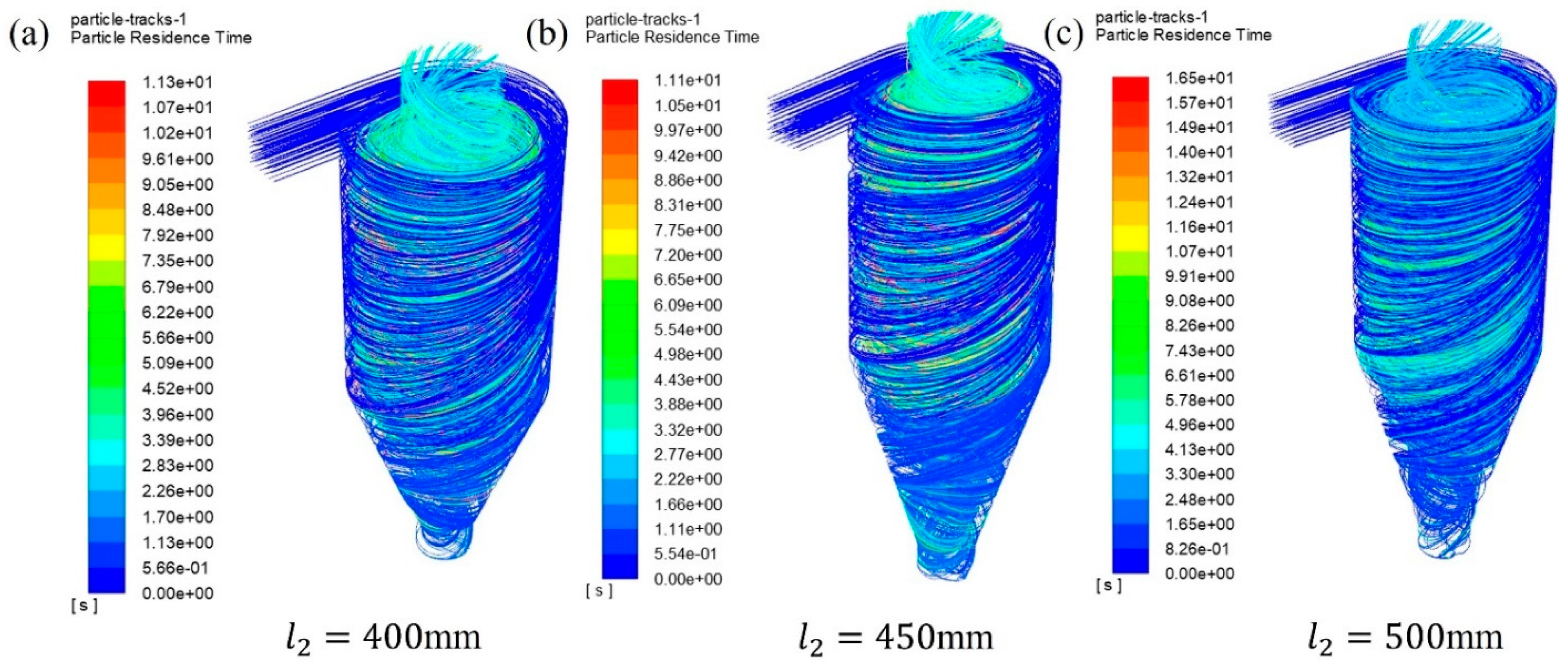
3.2. Effect of Different Sloping Wall Heights on Separation Performance

Keeping the inlet velocity constant at 5 m/s, the radius of the upper discharge opening was selected in this study to be 90 mm, and its effect on the performance of the cyclone separator in separating cenospheres was analyzed by varying the height of the sloping wall. The purpose of this analysis is to investigate the specific effect of changing the height of the sloping wall on the separation efficiency and other performance indexes. Figure 6 shows the velocity vector plots derived from simulation calculations for sloping wall heights l 2 of 400 mm, 450 mm, and 500 mm, respectively, and Figure 7 shows the particle trajectory plots for different sloping wall heights l 2 .
When simulating the cyclone separator, by varying the size of the sloping wall height l 2 , we can observe, as shown in Figure 6, that the velocity vector diagram remains relatively stable under the change in the sloping wall height. Furthermore, as shown in Figure 7, by carefully analyzing the particle movement at the upper discharge opening, it was found that the number of escaping particles also shows a decreasing trend with the gradual decrease in the sloping wall height. In addition, as shown in Table 4, the decrease in sloping wall height was accompanied by a continuous decrease in separation efficiency and Newton’s efficiency.

3.3. Effect of Different Incidence Velocities on Separation Performance

Under the selected conditions of an upper discharge opening radius of 90 mm and sloping wall height of 400 mm, this study analyzes the specific effect of incidence velocity on the performance of the cyclone separator in separating cenospheres by varying the incidence velocity. This analysis contributes to an in-depth understanding of the effect of varying the incident velocity on the separation efficiency and other related performance metrics. Incidence velocities of 2.5 m/s, 5 m/s, 7.5 m/s, 10 m/s, and 12.5 m/s were selected. Figure 8 shows the velocity vector diagrams derived from simulations with incident velocities ν of 2.5 m/s, 5.0 m/s, 7.5 m/s, 10.0 m/s, and 12.5 m/s, respectively. Figure 9 shows the particle trajectory diagrams for different incident velocities ν.
As shown in Figure 9, the number of escaping particles tends to decrease with decreasing incident velocity. The data in Table 5 show that the Newton’s efficiency decreases gradually with the decrease in the incident velocity, and when the incident velocity is 2.5 m/s, the Newton’s efficiency reaches 0.55. On the contrary, when the incident velocity is increased to 12.5 m/s, the separation efficiency of the cenospheres decreases to 6.3%, and the Newton’s efficiency decreases to −0.406. The reason for this phenomenon is that the increase in the incident velocity results in the enhancement of the centrifugal force, which makes the cenospheres continue to rotate inside the cyclone without being discharged from the upper discharge opening. From the results, it is concluded that the separation of cenospheres is significantly affected by the incident velocity. When the velocity is too large, the Newtonian efficiency decreases to a negative number.

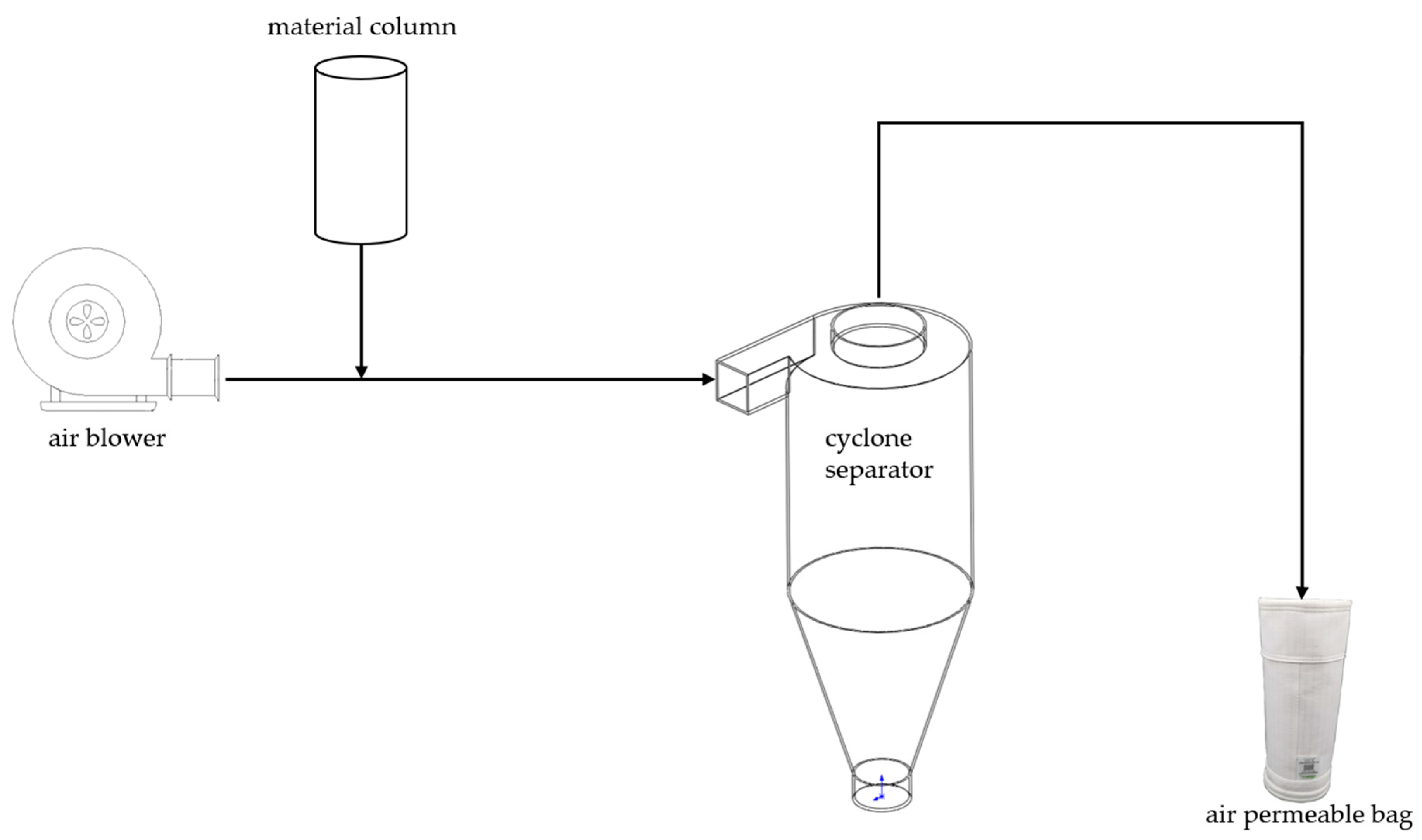
4. Experimental Part

4.1. Experimental Program

A flowchart of this experiment is shown in Figure 10. A mixture of fly ash and cenospheres is poured into the material column, and a blower blows the mixture into the cyclone. The initial separation of the mixture occurs in the cyclone. The less dense particles will enter the bag from the upper discharge port of the cyclone, and the more dense particles will be deposited at the bottom of the cyclone. When the experiment is over, the valve at the bottom of the cyclone is opened, and the waste material is collected. Newton’s efficiency was calculated by detecting the content of cenospheres in the waste. Figure 11 depicts the experimental bench system for this study. The experimental cyclone separator was customized to follow the above simulated structure to verify the accuracy of the simulation results. The air blower was a G-series frequency-controlled blower.

4.2. Experimental Procedure

Because the fly ash used in the experiment had a low content of less than 1% of cenospheres, this experiment was configured with a 15% content of cenospheres. We poured the configured mixture into the material column, started the blower, set the speed to 16 m/s, ran it for 1 h, and then turned off the blower and took out the bottom waste. The total weight of the configured mixture was w 1 . The total weight of the collected waste was w 2 .
The floating and sinking method was used to measure the content of hollow cenospheres in the waste material, that is, the waste material was poured into the water, stirred, and left to stand for 10 min; the hollow cenospheres floating on the surface were collected and weighed after drying, and their weight was w 3 . The configured mixture was poured directly into the water, and the floating and sinking method was used to collect the floating material; the efficiency coefficient of the floating and sinking method was measured as k = 0.582 .
η = w 1 × 15 % w 3 k w 1 × 15 % 1 w 2 w 3 k w 1 × 85 %
Equation (6) shows the calculation of the Newton’s efficiency. After the experiment, the data were as follows: w 1 = 200   g , w 2 = 155.04   g , w 3 = 5.47   g . The final Newton’s efficiency η was obtained as 0.543.

5. Conclusions

In this study, we proposed and simulated a dry separation technique that employed a cyclone separator to validate its effective separation of cenospheres. In order to achieve this goal, we carefully designed and constructed a model of the cyclone separator and performed an exhaustive performance analysis of the model through computational fluid dynamics simulations. In particular, we focused on three key design parameters, namely, the radius of the upper discharge opening, the height of the sloping wall, and the material incidence velocity, and evaluated their effects on the separation efficiency. The simulation results reveal that the upper discharge opening radius has a relatively small effect on the separation performance, whereas the variation of the slant wall height and the incidence velocity has a significant effect on the separation efficiency. During the parameter optimization process, we found that the Newton’s efficiency was significantly improved under the conditions of lower slant wall height and incident velocity. Specifically, when the radius of the upper discharge opening is set to 90 mm, the height of the sloping wall is 400 mm, and the incidence velocity is 2.5 m/s, the Newton’s efficiency can reach the optimal value of 0.55. The optimal Newtonian efficiency obtained from this simulation is not much different from the Newtonian efficiency of wet separation. This result not only shows the potential of dry separation technology but also provides a strong impetus for further research on the dry separation of cenospheres.
The Newton’s efficiency obtained through specific experiments is 0.543, which is not much different from the simulation results. However, the blower speed set in the experimental process is 16 m/s, which is different from the simulation. Because in the experimental process this study has directly sent the fly ash cenospheres mixture through the material column, the speed is too small, and the mixture is deposited in the pipe and cannot be blown into the cyclone by the wind, and the simulation gives the initial speed of the mixture, so the experiment will have a partial difference with the simulation. However, both the simulations and experiments show that the cyclone can be used as a separator for cenospheres.

Author Contributions

Conceptualization, P.H.; methodology, P.H.; validation, R.S.; formal analysis, R.S.; data curation, R.S.; writing—original draft, R.S.; writing—review and editing, R.S., T.H., K.H. and Q.C.; visualization, P.H.; supervision, P.H., S.Y., N.C. and J.W.; project administration, N.C. and J.W. All authors have read and agreed to the published version of the manuscript.

Funding

This work was partially sponsored by the “National Key R&D Program of China” (2021YFE0109800).

Institutional Review Board Statement

Not applicable.

Informed Consent Statement

Not applicable.

Data Availability Statement

The data presented in this study are available on request from the corresponding author.

Conflicts of Interest

The authors declare no conflict of interest.

References

  1. Ranjbar, N.; Kuenzel, C. Cenospheres: A review. Fuel 2017, 207, 1–12. [Google Scholar] [CrossRef]
  2. Kolay, P.K.; Bhusal, S. Recovery of hollow spherical particles with two different densities from coal fly ash and their characterization. Fuel 2014, 117, 118–124. [Google Scholar] [CrossRef]
  3. Mathapati, M.; Amate, K.; Prasad, C.D.; Jayavardhana, M.L.; Raju, T.H. A review on fly ash utilization. Mater. Today Proc. 2022, 50, 1535–1540. [Google Scholar] [CrossRef]
  4. Acar, I.; Atalay, M.U. Characterization of sintered class F fly ashes. Fuel 2013, 106, 195–203. [Google Scholar] [CrossRef]
  5. Dewan, S. Ash Flood in Tennessee Is Found to Be Larger Than Initial Estimates. New York Times, 26 December 2008; p. 10. [Google Scholar]
  6. Blissett, R.S.; Rowson, N.A. A review of the multi-component utilisation of coal fly ash. Fuel 2012, 97, 1–23. [Google Scholar] [CrossRef]
  7. Ngu, L.-n.; Wu, H.; Zhang, D.-k. Characterization of Ash Cenospheres in Fly Ash from Australian Power Stations. Energy & Fuels 2008, 21, 3437–3445. [Google Scholar] [CrossRef]
  8. Arizmendi-Morquecho, A.; Chavez-Valdez, A.; Vargas, G. Ultra-low thermal conductivity thermal barrier coatings from recycled fly-ash cenospheres. Acta Mater. 2011, 59, 2556–2562. [Google Scholar] [CrossRef]
  9. Yao, Z.T.; Ji, X.S.; Sarker, P.K.; Tang, J.H.; Ge, L.Q.; Xia, M.S.; Xi, Y.Q. A comprehensive review on the applications of coal fly ash. Earth-Sci. Rev. 2015, 141, 105–121. [Google Scholar] [CrossRef]
  10. Quijorna, N.; Miguel, G.S.; Andrés, A. Incorporation of Waelz Slag into Commercial Ceramic Bricks: A Practical Example of Industrial Ecology. Ind. Eng. Chem. Res. 2011, 50, 5806–5814. [Google Scholar] [CrossRef]
  11. Iyer, R.S.; Scott, J.A. Power station fly ash—A review of value-added utilization outside of the construction industry. Resour. Conserv. Recycl. 2001, 31, 217–228. [Google Scholar] [CrossRef]
  12. Yih, S.M.; Tu, C.; Kuto, S.T.; Quo, L.W. Recovery of cenospheres and application to the manufacture of insulation materials. J Chin. Inst. Chem. Eng. 1988, 19, 23–29. [Google Scholar]
  13. Kolay, P.K.; Singh, D.N. Physical, chemical, mineralogical, and thermal properties of cenospheres from an ash lagoon. Cem. Concr. Res. 2001, 31, 539–542. [Google Scholar] [CrossRef]
  14. Jha, N.; Badkul, A.; Mondal, D.P.; Das, S.; Singh, M. Sliding wear behaviour of aluminum syntactic foam: A comparison with Al–10 wt% SiC composites. Tribol. Int. 2011, 44, 220–231. [Google Scholar] [CrossRef]
  15. Chalivendra, V.B.; Shukla, A.; Bose, A.; Parameswaran, V. Processing and mechanical characterization of lightweight polyurethane composites. J. Mater. Sci. 2003, 38, 1631–1643. [Google Scholar] [CrossRef]
  16. Cardoso, R.J.; Shukla, A.; Bose, A. Effect of particle size and surface treatment on constitutive properties of polyester-cenosphere composites. J. Mater. Sci. 2002, 37, 603–613. [Google Scholar] [CrossRef]
  17. Parameswaran, V.; Shukla, A. Processing and characterization of a model functionally gradient material. J. Mater. Sci. 2000, 35, 21–29. [Google Scholar] [CrossRef]
  18. Wasekar, P.A.; Kadam, P.G.; Mhaske, S.T. Effect of Cenosphere Concentration on the Mechanical, Thermal, Rheological and Morphological Properties of Nylon 6. J. Miner. Mater. Charact. Eng. 2012, 11, 807–812. [Google Scholar] [CrossRef]
  19. Rohatgi, P.; Gupta, N.; Schultz, B.; Luong, D. The synthesis, compressive properties, and applications of metal matrix syntactic foams. JOM 2011, 63, 36–42. [Google Scholar] [CrossRef]
  20. Shunmugasamy, V.C.; Gupta, N.; Nguyen, N.Q.; Coelho, P.G. Strain rate dependence of damage evolution in syntactic foams. Mater. Sci. Eng. A 2010, 527, 6166–6177. [Google Scholar] [CrossRef]
  21. Ozcivici, E.S.; Raman, P. Fabrication and Characterization of Ceramic Foams Based on Silicon Carbide Matrix and Hollow Alumino-Silicate Spheres. J. Am. Ceram. Soc. 2005, 88, 3338–3345. [Google Scholar] [CrossRef]
  22. Lilkov, V.; Djabarov, N.; Bechev, G.; Petrov, O. Properties and hydration products of lightweight and expansive cements Part II. Cem. Concr. Res. 1999, 29, 1641–1646. [Google Scholar] [CrossRef]
  23. Barbare, N.; Shukla, A.; Bose, A. Uptake and loss of water in a cenosphere-concrete composite material. Cem. Concr. Res. 2003, 33, 1681–1686. [Google Scholar] [CrossRef]
  24. Acar, I.; Atalay, M.U. Recovery potentials of cenospheres from bituminous coal fly ashes. Fuel 2016, 180, 97–105. [Google Scholar] [CrossRef]
  25. Fomenko, E.V.; Anshits, N.N.; Solovyov, L.A.; Mikhaylova, O.A.; Anshits, A.G. Composition and Morphology of Fly Ash Cenospheres Produced from the Combustion of Kuznetsk Coal. Energy Fuels 2013, 27, 5440–5448. [Google Scholar] [CrossRef]
  26. McCarthy, G.J. Mineralogy of western (US) fly ash. Cem. Concr. Res. 1984, 14, 471–478. [Google Scholar] [CrossRef]
  27. Law, H.-S.; Masliyah, J.H.; MacTaggart, R.S.; Nandakumar, K. Gravity separation of bidisperse suspensions: Light and heavy particle species. Chem. Eng. Sci. 1987, 42, 1527–1538. [Google Scholar] [CrossRef]
  28. Yoriya, S.; Intana, T.; Tepsri, P. Separation of Cenospheres from Lignite Fly Ash Using Acetone–Water Mixture. Appl. Sci. 2019, 9, 3792. [Google Scholar] [CrossRef]
  29. Borm, P.J.A. Toxicity and occupational health hazards of coal fly ash (CFA). A review of data and comparison to coal mine dust. Ann. Work. Expo. Health 1997, 41, 659–676. [Google Scholar] [CrossRef]
  30. Shapiro, M.; Galperin, V. Air classification of solid particles: A review. Chem. Eng. Process. Process. Intensif. 2005, 44, 279–285. [Google Scholar] [CrossRef]
  31. Hirajima, T.; Petrus, H.T.B.M.; Oosako, Y.; Nonaka, M.; Sasaki, K.; Ando, T. Recovery of cenospheres from coal fly ash using a dry separation process: Separation estimation and potential application. Int. J. Miner. Process. 2010, 95, 18–24. [Google Scholar] [CrossRef]
  32. Hoffmann, A.; Stein, L.; Bradshaw, P. Gas Cyclones and Swirl Tubes: Principles, Design and Operation. Appl. Mech. Rev. 2003, 56, B28–B29. [Google Scholar] [CrossRef]
  33. Zhou, F.; Sun, G.; Zhang, Y.; Ci, H.; Wei, Q. Experimental and CFD study on the effects of surface roughness on cyclone performance. Sep. Purif. Technol. 2018, 193, 175–183. [Google Scholar] [CrossRef]
  34. Yao, Y.; Huang, Z.; Zhang, M.; Yang, H.; Lyu, J.; Wang, J. Effects of the Y-shape stud and outer insulating layer on heat dissipation and wall temperature of the hot cyclone in a circulating fluidized bed boiler. Appl. Therm. Eng. 2022, 204, 117989. [Google Scholar] [CrossRef]
  35. Pukkella, A.K.; Cilliers, J.J.; Hadler, K. A comprehensive review and recent advances in dry mineral classification. Miner. Eng. 2023, 201, 108208. [Google Scholar] [CrossRef]
Figure 1. Cyclone separator model structure schematic.
Applsci 14 05132 g001
Figure 2. Cyclone separator meshing diagram.
Applsci 14 05132 g002
Figure 3. Velocity vectors for different upper discharge opening radii.
Applsci 14 05132 g003
Figure 4. Particle trajectory plots for different radii of the upper discharge opening.
Applsci 14 05132 g004
Figure 5. Newton’s efficiency for different upper discharge opening radii.
Applsci 14 05132 g005
Figure 6. Velocity vectors for different sloping wall heights.
Applsci 14 05132 g006
Figure 7. Particle trajectory plots for different sloping wall heights.
Applsci 14 05132 g007
Figure 8. Velocity vector plots for different incident velocities.
Applsci 14 05132 g008
Figure 9. Particle trajectories for different incidence velocities.
Applsci 14 05132 g009
Figure 10. Flowchart of the experimental program.
Applsci 14 05132 g010
Figure 11. Laboratory bench system.
Applsci 14 05132 g011
Table 1. Cyclone separator model size table.
Model Parameters
l 1 Lower discharge tube height/mm60
l 2 Sloping wall height/mm450
l 3 Separation chamber height/mm600
l 4 Length of feed tube/mm200
l 5 Inlet height/mm90
l 6 Height of upper discharge opening/mm30
d 1 Separation chamber radius/mm200
d 2 Lower discharge opening radius/mm60
d 3 Upper discharge radius/mm90
Table 2. Grid independence study table.
Number of GridsSeparation Efficiency of Cenospheres
γ A (%)
Fly Ash Separation Efficiency
γ B (%)
Newton’s Efficiency
η N
24,78692.8647.020.457
29,12093.3346.110.472
42,45695.7647.640.4812
52,08995.7147.370.4834
Table 3. Efficiency with different upper discharge opening radii.
Upper Discharge Radius
d 3 (mm)
Separation Efficiency of Cenospheres
γ A (%)
Fly Ash Separation Efficiency
γ B (%)
Newton’s Efficiency
η N
6092.6846.950.457
7092.6846.950.457
8089.0245.120.439
9092.8647.020.458
10091.6744.640.470
Table 4. Efficiency of different sloping wall heights.
Sloping Wall Height
l 2 (mm)
Separation Efficiency of Cenospheres
γ A (%)
Fly Ash Separation Efficiency
γ B (%)
Newton’s Efficiency
η N
40093.75450.488
45092.8647.020.458
50077.536.250.412
Table 5. Efficiency for different incidence velocities.
Incidence Velocity
ν (m/s)
Separation Efficiency of Cenospheres
γ A (%)
Fly Ash Separation Efficiency
γ B (%)
Newton’s Efficiency
η N
2.592.537.50.55
5.093.75450.488
7.591.2547.50.438
10.08036.90.431
12.56.346.9−0.406
Disclaimer/Publisher’s Note: The statements, opinions and data contained in all publications are solely those of the individual author(s) and contributor(s) and not of MDPI and/or the editor(s). MDPI and/or the editor(s) disclaim responsibility for any injury to people or property resulting from any ideas, methods, instructions or products referred to in the content.

