Article

Experimental Analysis and Numerical Modelling of the Mechanical Behavior of a Sisal-Fiber-Reinforced Geopolymer

by
Salvatore Benfratello
,
Antonino Cirello
,
Luigi Palizzolo
*,
Carmelo Sanfilippo
and
Antonino Valenza
Department of Engineering, University of Palermo, Viale delle Scienze, 90128 Palermo, Italy
*
Author to whom correspondence should be addressed.
Appl. Sci. 2024, 14(12), 5216; https://doi.org/10.3390/app14125216
Submission received: 8 May 2024 / Revised: 11 June 2024 / Accepted: 12 June 2024 / Published: 15 June 2024

Abstract

:
The present paper is devoted to the proposal of appropriate numerical modelling able to provide a suitable description of the mechanical behavior of a composite geopolymer. Reference is made to a natural sisal-fiber-reinforced geopolymer. The study is based on the results of appropriate experimental investigations for compressive, flexural and splitting loadings, taking into account different weight percentages of fibers to evidence their role in the mechanical behavior. The main objective of the paper is to calibrate the microplane constitutive model, available in ANSYS software version 18.1, where the numerical analyses are performed. Therefore, the present study is structured in two different steps. Firstly, the mechanical behavior of geopolymers reinforced with sisal fibers is experimentally investigated, and subsequently, the gathered test data are interpreted and utilized to calibrate the relevant constitutive model to be used in the numerical stage. The obtained results are compared with experimental data, yielding good correlations. The paper’s results supply the parameters required to obtain an affordable numerical model of the reinforced geopolymer for different percentages of fibers to be adopted for material design with assigned mechanical properties.

1. Introduction

In the last decades, the increasing problem of waste management all over the world has led to the definition and implementation of different strategies to achieve sustainable environments in the framework of the so-called circular economy. In this framework, specific attention is paid to the construction industry, which is regarded as more responsible for the high usage of raw materials than any other industry, mainly due to the manufacturing of ordinary Portland cement (OPC). To mitigate this impact, several alternative materials are being developed and used with the aim of reducing CO2 emissions and improving the overall sustainability of the construction industry. In recent years, geopolymers have gained popularity as possible substitutes for OPC due to some of their characteristics, such as low energy consumption, low carbon dioxide emissions, high compressive strength, fire resistance and good durability. However, geopolymers are fragile ceramic materials, with relatively low tensile strength and are sensitive to micro-fissure propagation. To address these limitations, they can be used as packaged matrices by adding fibers, limiting crack propagation and improving ductility, toughness and tensile strength. With respect to other cementitious media in which the use of natural fibers possesses many drawbacks (see, e.g., [1,2]), geopolymers have the additional advantage of using very little water for their preparation resulting in a very compact media enveloping the fibers. A further advantage is their low environmental impact since they can be realized with industrial by-products, such as coal fly-ash, high-temperature glass slag mine tailings or construction wastes, which are usually accumulated as waste. On the other hand, nowadays, geopolymers possess some disadvantages mainly related to their production costs and difficulty in handling due to high alkalinity. Anyway, these disadvantages do not invalidate their use and the interest for the development of further detailed scientific studies, and it is reasonable to expect that these disadvantages can be overcome in the future with the development of related technology and the increment of grants from public and private institutions.
When interventions with existing buildings are performed (e.g., restoration and/or updating), the construction industry is also responsible for construction wastes, which are actually treated as special wastes outside the virtuous paths of waste recycling. Due to these remarks, the international research has focused on the definition of eco-friendly alternatives to OPC (see, e.g., [3,4,5]), and growing attention has addressed geopolymers [6] as construction materials [7]. Geopolymer production is mainly obtained from raw materials based on aluminosilicate (referred to as precursors), alkaline activators and other elements [8]. Theses specific features lead the geopolymers to be considered as “cement-free” materials for which production can be achieved by using by-products [9,10,11]. Another remark on behalf of geopolymers as eco-friendly materials [12] is that the CO2 emissions and energy savings required in the manufacturing process of geopolymers are lower than for OPCs [8]. From a mechanical point of view geopolymers show characteristics common to concrete-like materials and are attracting the interest of civil engineering industries [13,14]: good compressive behavior (both in strength and in stiffness), brittle behavior in tension, characterized by low tensile strength and energy fracture values [15], and sensitivity to early-age shrinkage [16]. As it has been already performed in concrete engineering, to overcome the drawbacks in tensile behavior and to enhance the ductility, the reinforcement of geopolymers with different kind of fibers has been investigated (see, e.g., [12,17] for steel fibers, [18,19,20] for glass fibers, [21,22] for carbon fibers and [23,24] for basalt fibers). On the other hand, in the framework of a circular economy and waste recycling, the interest in adopting plant-based natural fibers as reinforcement has attracted great interest among researchers. These kinds of fibers possess interesting specific engineering properties, such as mechanical characteristics and sound and thermal insulation, together with interesting specific economical properties, such low raw material cost, low-cost processing and large availability [25]. Furthermore, from a green-economy point of view, these fibers show many interesting properties since they are renewable and biodegradable and show a carbon-dioxide-neutral life-cycle [26]. All of these remarks have led, in the last years, several authors to address research regarding the utilization of natural fibers as reinforcements for geopolymer materials [27]. Among these studies, it is worth noting that [28] reported a preliminary investigation to evaluate the compatibility of metakaolin-based geopolymers with several natural fibers being carried out. The fibers considered in this research were classified as wood and non-wood ones, and the results of the experimental campaign showed that wood fibers are more compatible with the geopolymeric matrix in comparison to non-wood fibers. The research reported in [29] investigated the role of the cotton fiber weight content (in the range 0.3–1.0%) based on the physical, mechanical and fracture behavior of fly-ash-based geopolymers. The results showed that a fiber weight content equal to 0.5% leads to optimal mechanical performances in terms of fracture toughness and flexural strength. The presence of an optimal value of fiber weight replacement is reasonable since the increment in mechanical performance of the geopolymer composite due to the fibers is compensated for by both the porosity and fiber agglomeration increment (leading to a reduction in the density of the geopolymer composites). Among natural fibers, sisal ones are recognized as those with high mechanical performances due to their composition (65–68% cellulose, 10–22% hemicellulose and 10–14% lignin). Sisal fibers also possess further advantages: their length is between 1 and 1.5 m (allowing the use also for high-dimension samples), the diameter is about 100–300 µm with a smooth diameter profile along the fiber and the productivity is high (about 12 years life, 120 and 240 leaves for each plant and about 1000 fibers for each leaf). For more detailed information about sisal fibers, see [1,2].
For an overall review regarding the processing and properties of geopolymers reinforced with natural fibers see [27]. In the research reported in [30], the geopolymer composite was produced using a matrix obtained from fired clay brick wastes adopting short sisal and jute fibers as reinforcement. The obtained results evidenced a meaningful increment in the mechanical properties of fiber reinforced geopolymers with respect to unreinforced material showing good fiber–matrix adhesion for both examined natural fibers. Furthermore, in [30], it was also shown that—due to the presence of both natural fibers—the failure mode of the composite changes from a brittle to more ductile one and that the post-peak behavior is strongly influenced. On the other hand, the role played by geopolymers in the construction industry is confirmed by many papers in which the use of geopolymers as the basis of concrete (with or without recycled aggregates) to be adopted in structural members is investigated [31].
To support and develop the adoption of natural-fiber-reinforced geopolymers (mortar and/or concrete) in the construction industry, it is fundamental to define a suitable and affordable numerical model of the mechanical behavior of the relevant material to be introduced in Finite Element Method (FEM) software allowing for an evaluation of the acting stress–strain fields. This aspect is worthy of investigation, and few papers have been devoted to this topic (see, e.g., [32,33,34,35,36]). The aim of this work is to a further progress in the numerical modelling of sisal-fiber-reinforced geopolymer mortar, starting from experimental tests (compressive, three-point bending and splitting tests) performed with different percentages of fiber reinforcement. Many constitutive numerical models are available in the literature for concrete-like materials, and the corresponding parameters should be suitably calibrated starting from experimental results to capture the mechanical characteristics related to fiber reinforcement (e.g., the improvement in both hardening and softening phases). Among these constitutive numerical models, one of the most versatile for concrete-like materials is the microplane model [37,38,39,40] available in ANSYS Finite Element Method (FEM) software [41]. Therefore, in this paper, the numerical analyses have been performed with the commercial software ANSYS, numerically modelling the experimental tests and calibrating the required parameters to obtain satisfactory accuracy, considering the different percentages of fiber reinforcement. The obtained results are the material model parameters (depending on the fiber percentage) required to characterize the material behavior in the ANSYS environment to be adopted in future analyses for the evaluation of structural elements realized with such geopolymer composite materials. The results proposed in this paper can also be usefully adopted to design a geopolymer composite material with assigned mechanical characteristics.

2. Materials and Methods

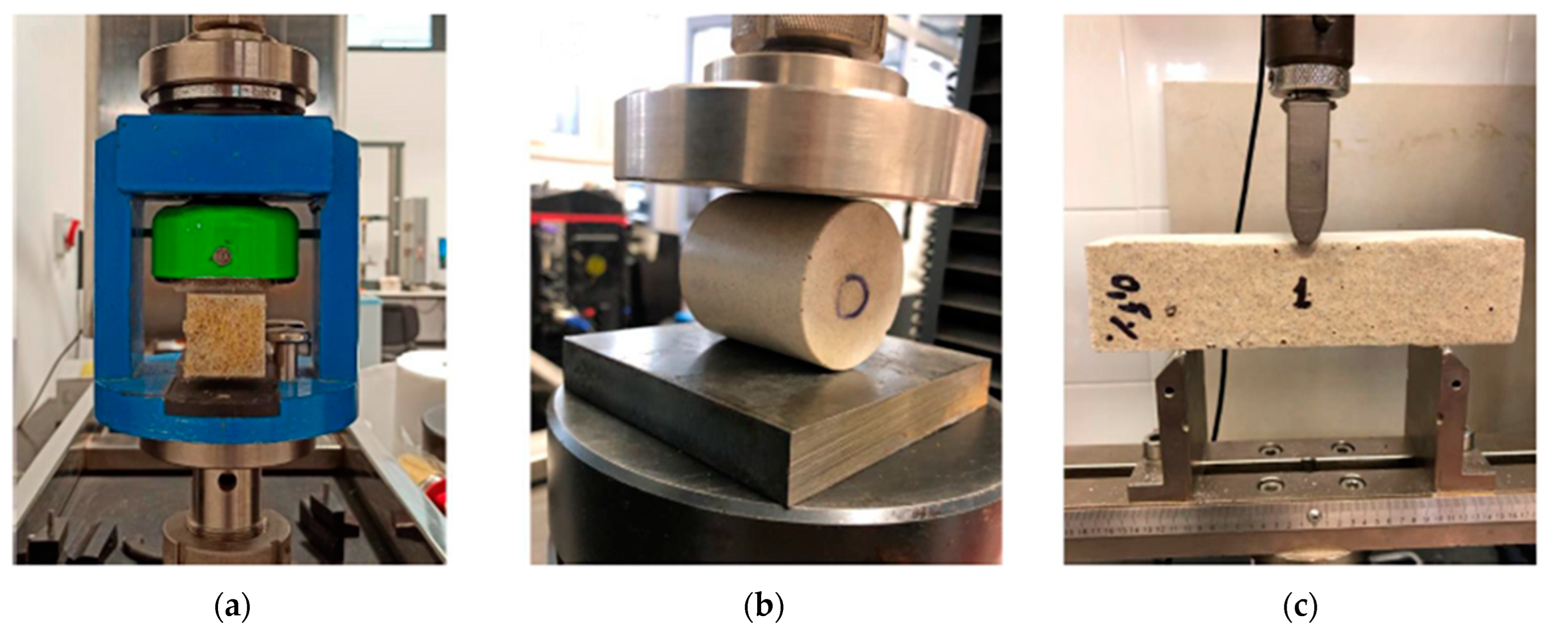
2.1. Experimental Tests

To realize the geopolymer composites to be tested experimentally, as described in the following, two different steps were performed. In the first one, the matrix was prepared by selecting metakaolin as the precursor (silicon-to-aluminum molar ratio equal to 1.3:1 with a grain size distribution ranging between 1 μm and 100 μm). The alkaline activator was a 7 M potassium peroxide alkaline solution, obtained by mixing KOH pellets (99% purity) and potassium silicate (K2O·nSiO2) powder with deionized water. The reagents to obtain the alkaline solution were supplied by Carlo Erba Reagents S.r.l. (Cornaredo, Italy). The selected aggregate was river sand with a nominal maximum diameter of 2 mm. In the second step, the sisal fibers were suitably mixed by replacing different weight contents (0.5%, 1% and 2%) of the aggregate. The sisal fibers, obtained from plants cultivated in northern Sicily, were prepared by washing and subsequent drying at 25 °C for 48 h; the adopted fibers were not treated, with the role of treatment in the mechanical behavior being the object of an ongoing study. For a review about the influence of the fiber treatment on the mechanical behavior of geopolymer matrices, see [42]. Following the results reported in [15], the sisal fibers were shortened by a suitable cut to the selected final length equal to 2.5 mm. The upper limit of the replacement of the aggregate with fibers is because, as reported in [39], regardless of the fiber types, the increase in compressive strength is more expectable when the fiber content is less than 2%, while above this value, an adverse effect of the fiber is possible. The geopolymer composite samples, realized as described before, were cured at room temperature for 2 -days and identified with an “MK-x” acronym, where “MK” refers to the precursor and “x” to the sisal weight content (e.g., MK-0 refers to the reference material that is unreinforced geopolymer mortars).
The mechanical behavior of the geopolymer samples with and without sisal fibers was assessed through a wide campaign of experimental tests. The selected tests were those prescribed by the actual standards (UNI EN 1015-11 [43] and ASTM D3967 [44]) for mortars, consisting of compression, bending and splitting (Brazilian indirect tensile) tests. Following [43], the specimens consisted of prismatic samples with nominal dimensions ( b × h × l ) equal to 40 mm × 40 mm × 160 mm to be tested in a three-point bending configuration, while the specimens for the compression test (cube specimens with side dimension of about 40 mm) were derived by cutting the fragments obtained at the end of the bending test. Finally, the span length in the bending test was set equal to 100 mm. Following [44], the specimens for the splitting test were cylindrical with a nominal diameter ( d ) and height ( h ) equal to 50 mm and 30 mm, respectively ( h / d ratio equal to 0.6). The mechanical tests were carried out using the universal testing machine (UTM) model ETM-C (WANCE, Shenzhen, China), equipped with a 50 kN load cell. Bending and compression tests were performed in displacement control with a pre-load equal to 10 N, the bending one with a rate of 1 mm/min, while the compression one had a rate of 0.5 mm/min. The splitting test was performed in stress control with a rate equal to 0.05 MPa/s. Three specimens were tested for each mechanical test, and in Figure 1, the corresponding test set-ups are reported.

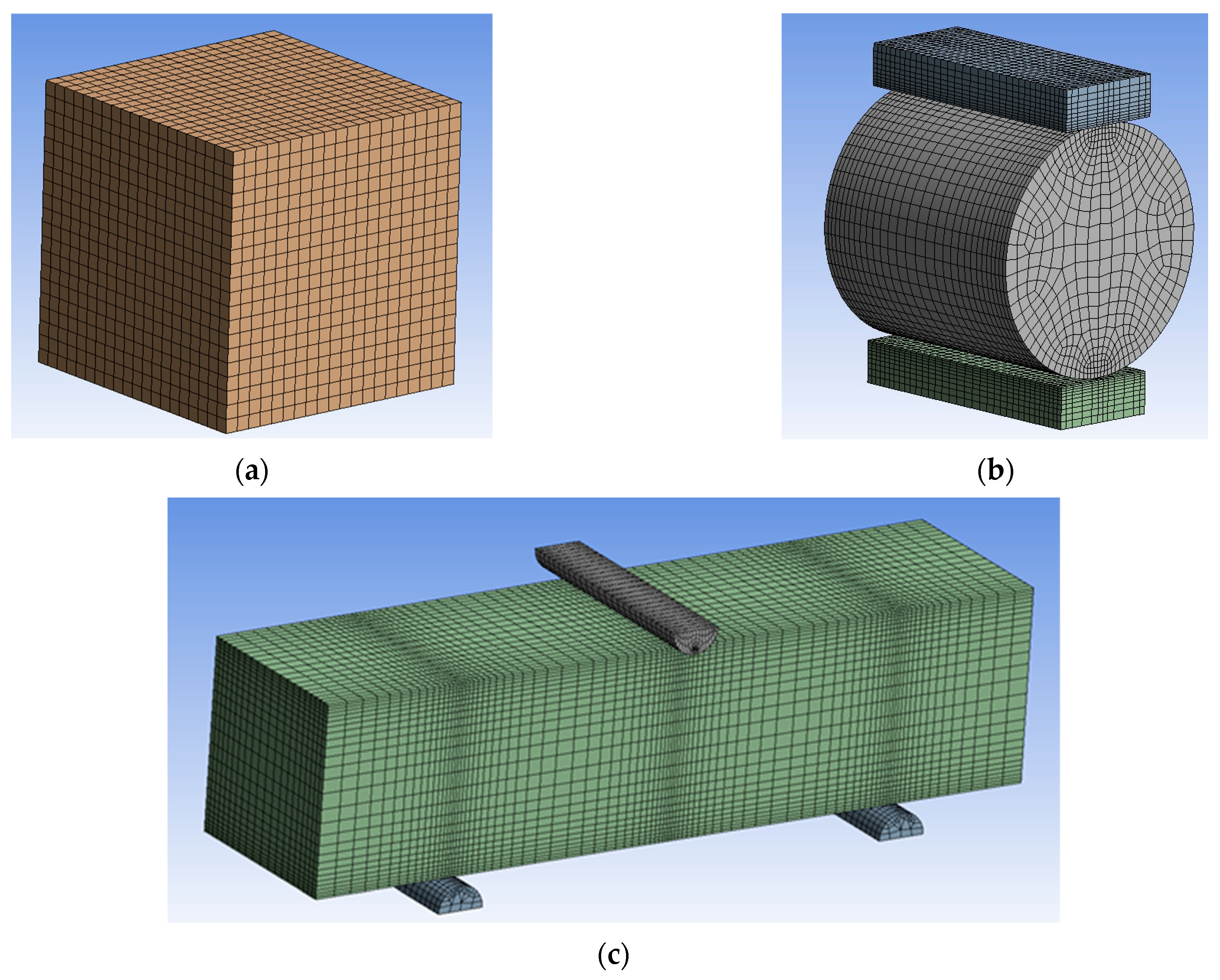
2.2. Numerical Modelling

As it has been reported in the introduction, to increase and develop the use of a geopolymer mortar (with or without fibers) in the construction industry, a fundamental step is to check the affordability of the available material model to be implemented in FEM software. This remark is even more important for the geopolymers intended as a new type of concrete, and therefore, affordable numerical models are required to design structures realized with such materials. Among FEM software, ANSYS is one of the leading one, and it was adopted in this paper to numerically reproduce the experimental results reported in the next section. As a material model available in the ANSYS library, the selected one was the coupled damage-plasticity microplane, which is regarded as very affordable in the case of simulating engineering materials consisting of various aggregate compositions with differing properties (for example, concrete modeling, in which rock and sand are embedded in a weak matrix of cements). The numerical analysis was performed iteratively assuming the Young’ modulus E , the ultimate strength in compression and that of the splitting test (obtained from the experimental tests as described in the next section) and the Poisson ratio ν (equal to 0.2, from literature) as known parameters. The microplane model requires the following parameters to be assigned: the biaxial strength f b , the coefficient D (governing the hardening of the material), the γ c 0 , γ t 0 , β c and β t parameters, which govern the damage behavior ( γ c 0 and γ t 0 represent the damage thresholds, β c , and β t represents the damage evolution constants) in tension and in compression, the parameters R c and R t , representing the cap hardening constants (in compression and in tension, respectively) and the parameter σ c v (representing the intersection of the compression cap and Drucker–Prager yield function). A detailed explanation of the meaning of these parameters can be found in the ANSYS manual [41] and in the references reported. Following the suggestions in [41], for all the fiber contents, f b was set equal to 1.38 f c (compressive strength), and the parameter R c was set to 2, R t to 1, σ c v to −6.66 MPa and γ t 0 to zero. The adopted values of the remaining parameters are reported in Section 3.2. The first step was to perform preliminary analyses to check the mesh convergence, and in Figure 2, the adopted models for the compression, splitting and three-point bending tests are respectively reported. The element type for geopolymers was CPT215, whereas the supports were meshed with 8-node SOLID185. Surfaces subjected to contacts were meshed with a CONTA174 contact element assuming a frictional coefficient equal to 0.2. The analyses were conducted in the displacement control with a rate of 0.005 mm/min.

3. Results and Discussion

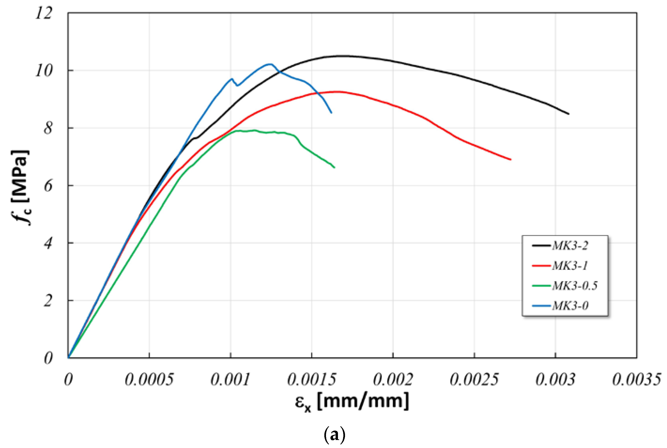
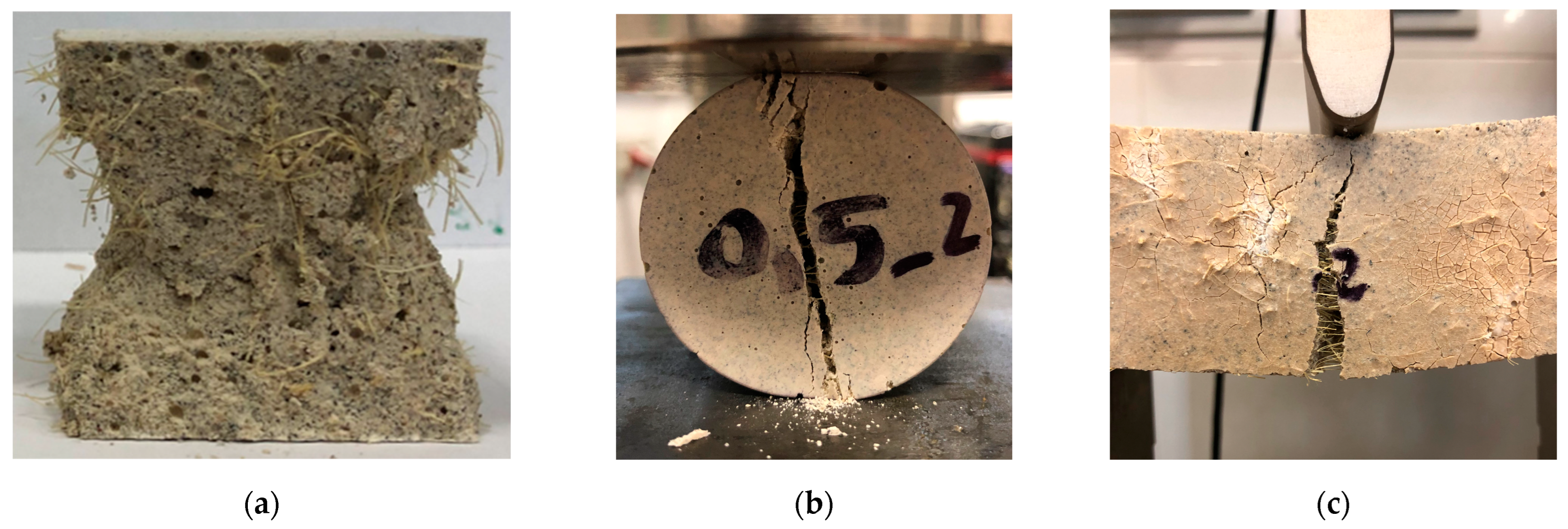
3.1. Experimental Results

In Figure 3, the obtained results for compression, three-point bending and splitting tests are respectively reported, while in Figure 4, images of one tested specimen are reported for each test. The results sketched in Figure 3 for each test are the mean of those obtained for each sample (three specimens for each test) and allow us to draw the following remarks: (a) in the compression test, the main contribution of the fibers is related to the great increment in the softening phase, which, on the contrary, is limited in the case of specimens without fibers; (b) the ultimate strength f c u increases when comparing the results of no-fiber specimens with those with a 2% of fiber content; (c) for intermediate fiber contents, the results show a decrement of f c u and a limited increment in the yield strength f c y with the fiber content. These results are different from those reported in [45] where, however, the length of the fiber is about 35 mm, 14 times greater than that adopted in the present study, also suggesting a dependency of the compressive strength on the fiber length. It must be noted that in [45], the replacement was performed as a volume fraction, while in the present paper, it was performed in terms of a weight fraction. As a result, the compression Young’ modulus is very close in all the cases except for the case of MK3-05, in which it is lower. The compression results confirm that for this type of loading, the contribution of the fiber content is not meaningful and the behavior is similar. The exception to this remark is the case of 0.5% of which the peculiar behavior should be related to some “defects” in the tested specimens. The reason of these “defects” must be related to the role of the porosity above the fiber’s critical concentration (usually between 0.2% and 2%) that, in the case under examination, is around 0.5% [15]. This aspect will be further investigated in the development of the research. Analogous remarks can be made in the case of the three-point bending test. The fiber content causes a significant increment in the softening phase with respect to the no-fiber content, an important increment in the ultimate strength f f u and a limited increment in the yield strength f f y . Further, it causes the onset of the hardening phase and a huge increment in the softening phase with an important consequence on the energy fracture as it will be described in the following. The analysis of SEM images (which are not reported in the paper only for brevity sake but are available as Supplemental Material) confirms the good bonding between fibers and the matrix for all examined cases. The Young’ modulus has been determined as the slope of the straight line interpolating the experimental results in the range 0.1–0.3 of the strength for both compression and bending tests.
To characterize the dependency of the mechanical behavior of the geopolymer composite on the fiber content yield and ultimate strengths, the Young’ modulus was identified for each batch and each test and plotted vs. the fiber content. In Figure 5, the limit elastic strength and the ultimate ones are respectively reported in terms of mean values and deviations. These results suggest that in the case of the splitting test, the dependency of both the yield and ultimate strength is lowest and that of the three-point bending test is the highest, while in the compression test, the dependency is intermediate. These results are coherent with those reported in [15,27,46]. This peculiar behavior can be ascribed to the presence of fibers, due to which the initiation and extension of cracks of mode I fracture, and potential shear stresses are reduced. This is because once a crack faces a fiber, it demands higher energy of the fracture to pull the fiber out and then propagate [15].
The fundamental role played by the fiber in the mechanical behavior of the material under examination can be further evidenced by examining Figure 6, where, for each mechanical test, the ratio between the ultimate strength and the yield strength is sketched. This ratio indicates the ability of the material to possess a hardening phase. As it is evident from Figure 6, in the case of compression, this ratio is almost independent from the fiber content, while in the case of the splitting test and three-point bending tests, this ratio shows an increment of about 40–60% (depending on the test) with the fiber content, confirming either its fundamental role in the tensile behavior of the material and the results reported in [44] and suggesting that, in this case, the fiber length does not greatly influence the results.
To further evaluate the influence of the fiber content on the mechanical behavior of the material, in Figure 7, the strength ratios f c u / f f u , f c u / f t u and f t u / f f u are sketched versus the fiber content. In all cases, the evolution of the curves is a decreasing one confirming, as reported in [46], that the fibers influence the flexural behavior more than the compressive and splitting ones and that this influence is greater in tensile behavior than in the compressive one. In Figure 8, the Young’ modulus in the case of compression and bending tests is sketched vs. the fiber content. The obtained result confirms the remark already made for Figure 3, i.e., the dependency of the relevant mechanical parameter on the fiber content is higher in the case of the three-point bending test.
Finally, to characterize the post-crack energy absorption ability induced by the fiber reinforcement and its dependency on the fiber content, in Figure 9a, the fracture energy determined from the experimental tests is sketched vs. the fiber content. The fracture energy G f defined as the amount of energy absorbed to create a unit area of a crack, which was determined starting from the stress–displacement curves obtained through the experimental tests, assuming a linear interpolation of the post-peak behavior to calculate the displacement at null stress; G f is calculated as the area under the post-peak behavior. It can be seen from the Figure that the role played by the fiber reinforcement is confirmed since, in all tests, G f increases with the fiber content. To enhance the stitching effect of the fibers in Figure 9b, the ratio between G f and its value in the absence of fibers ( G f , 0 ) is sketched vs. the fiber content. Also, in this case, the obtained result confirms the role of the fiber content, since in the test where tension stress arises significantly (i.e., bending and splitting tests), this ratio increases by up to more than 60 times in the bending test and more than 10 times in the splitting test, whereas in the compression test, this increment is around 5 times.

3.2. Numerical Results

As it has been reported in Section 2.2, the numerical analysis was performed iteratively to reproduce the experimental results. As it is explained in literature about the selected numerical model, all the characterizing parameters interact with each other to give the overall behavior. It follows that the selection of the best parameters of the numerical model is a complex task and, in the present paper, it was performed based on the following criteria: (a) the elastic phase must be reproduced correctly (maximum absolute error equal to 2%); (b) the strength of all the tests must be reproduced with a maximum absolute error equal to 10%; (c) the area under the compression and bending tests must be reproduced with a maximum absolute error equal to 10% and 20%, respectively.
The optimal material parameters obtained as described before are reported in Table 1 and graphically sketched in Figure 10.
The obtained numerical parameters allow us to draw the following remarks about the influence of the fiber content on the mechanical behavior of the material: (a) the damage threshold in compression γ c 0 is greatly influenced, and the corresponding stress–strain curve shows a decreasing spread around the peak; (b) the compression damage β c is influenced by the fiber content to a great extent with respect to the tension damage β t , which can be regarded as almost constant; (c) the hardening of the material (governed by parameter D ) is also strongly influenced by the fiber content.
The numerical simulations are reported in Figure 11 and compared with the experimental results. The obtained results show the good accuracy of the numerical results especially in the case of the compression test. The same results suggest that the proposed model can reproduce, in an approximate way, the post-elastic behavior in the case of splitting and three-point bending tests. An overall analysis of these results confirms the affordability of the adopted material model and that of the selected parameters suggesting a more extensive experimental and numerical campaign to improve the affordability of the numerical model for all mechanical tests.

4. Conclusions

In the present paper the experimental analysis and the numerical modelling of the mechanical behavior of a geopolymer reinforced with different weight percentages of sisal fibers have been presented. The obtained results can be summarized as follows: (a) the experimental analysis showed that the fibers strongly influence the mechanical behavior of the composite material especially in terms of the flexural and splitting test response with a great increment in the energy fracture of the material; (b) the coupled damage-plasticity microplane model adopted in the numerical modelling of the experimental tests gives satisfactory results, especially in terms of the elastic stiffness and strength for all tests; (c) the numerical post-elastic behavior is as much as satisfactory as the numerical elastic one in the case of compression test, while, in the case of the bending test, a great affordability is reached only for a high weight percentage of the fiber replacement; (d) the parameters of the numerical constitutive model reported in the paper allow it to be adopted for any percentage of fiber weight replacement in the range 0–2%. Future developments of the proposed research are the following: (a) the role of fibers in the softening phase must be further investigated to identify the critical fiber concentration; (b) the cyclic behavior of the material must be investigated both experimentally and numerically to additionally check the affordability of the numerical model.

Supplementary Materials

The following supporting information can be downloaded at: https://www.mdpi.com/article/10.3390/app14125216/s1, Figure S1: SEM image of the MK3-1 sample; Figure S2: SEM image of the MK3-2 sample; Figure S3: SEM image of the MK3-0.5 sample.

Author Contributions

Conceptualization, A.V.; experimental preparation and validation, C.S.; numerical analysis, S.B. and A.C.; numerical analysis, writing—original draft preparation, S.B.; writing—review and editing, L.P.; funding acquisition, A.V. All authors have read and agreed to the published version of the manuscript.

Funding

This research received no external funding.

Institutional Review Board Statement

Not applicable.

Informed Consent Statement

Not applicable.

Data Availability Statement

Data is contained within the article or Supplementary Material.

Conflicts of Interest

The authors declare no conflicts of interest.

References

  1. Lilargem Rocha, D.; Tambara Júnior, L.U.D.; Marvila, M.T.; Pereira, E.C.; Souza, D.; de Azevedo, A.R.G. A Review of the Use of Natural Fibers in Cement Composites: Concepts, Applications and Brazilian History. Polymers 2022, 14, 2043. [Google Scholar] [CrossRef]
  2. de Lima, T.E.S.; de Azevedo, A.R.G.; Marvila, M.T.; Candido, V.S.; Fediuk, R.; Monteiro, S.N. Potential of Using Amazon Natural Fibers to Reinforce Cementitious Composites: A Review. Polymers 2022, 14, 647. [Google Scholar] [CrossRef]
  3. Arcones-Pascual, G.; Hernández-Olivares, F.; Sepulcre-Aguilar, A. Comparative properties of a lime mortar with different metakaolin and natron additions. Constr. Build. Mater. 2016, 114, 747–754. [Google Scholar] [CrossRef]
  4. Majumder, A.; Stochino, F.; Frattolillo, A.; Valdes, M.; Mancusi, G.; Martinelli, E. Jute fiber-reinforced mortars: Mechanical response and thermal performance. J. Build. Eng. 2023, 66, 105888. [Google Scholar] [CrossRef]
  5. Greco, P.F.; Pepi, C.; Gioffré, M. A novel biocomposite material for sustainable constructions: Metakaolin lime mortar and Spanish broom fibers. J. Build. Eng. 2024, 83, 108425. [Google Scholar] [CrossRef]
  6. Davidovits, J. Geopolymers and geopolymeric materials. J. Therm. Anal. 1989, 35, 429–441. [Google Scholar] [CrossRef]
  7. Zhang, P.; Zheng, Y.; Wang, K.; Zhang, J. A review on properties of fresh and hardened geopolymer mortar. Compos. Part B Eng. 2018, 152, 79–95. [Google Scholar] [CrossRef]
  8. Turner, L.K.; Collins, F.G. Carbon dioxide equivalent (CO2-e) emissions: A comparison between geopolymer and OPC cement concrete. Constr. Build. Mater. 2013, 43, 125–130. [Google Scholar] [CrossRef]
  9. Alhawat, M.; Ashour, A.; Yildirim, G.; Aldemir, A.; Sahmaran, M. Properties of geopolymers sourced from construction and demolition waste: A review. J. Build. Eng. 2022, 50, 104104. [Google Scholar] [CrossRef]
  10. Zhang, P.; Gao, Z.; Wang, J.; Guo, J.; Wang, T. Influencing factors analysis and optimized prediction model for rheology and flowability of nano-SiO2 and PVA fiber reinforced alkali-activated composites. J. Clean. Prod. 2022, 366, 132988. [Google Scholar] [CrossRef]
  11. Lazorenko, G.; Kasprzhitskii, A.; Fini, E.H. Sustainable construction via novel geopolymer composites incorporating waste plastic of different sizes and shapes. Constr. Build. Mater. 2022, 324, 126697. [Google Scholar] [CrossRef]
  12. Guo, X.; Pan, X. Mechanical properties and mechanisms of fiber reinforced fly ash–steel slag based geopolymer mortar. Constr. Build. Mater. 2018, 179, 633–641. [Google Scholar] [CrossRef]
  13. Das, S.; Mohapatra, A.; Rath, A. Geo-polymer concrete-green concrete for the future—A review. Int. J. Civ. Eng. Res. 2014, 5, 2278–3652. [Google Scholar]
  14. Alhawat, M.; Yildirim, G.; Ashour, A.; Ozcelikci, E.; Aldemir, A.; Sahmaran, M. A study on the influencing parameters in developing construction and demolition waste-based geopolymer concretes and their sustainability assessment. Constr. Build. Mater. 2024, 426, 136143. [Google Scholar] [CrossRef]
  15. Ranjbar, N.; Zhang, M. Fiber-reinforced geopolymer composites: A review. Cem. Concr. Compos. 2020, 107, 103498. [Google Scholar] [CrossRef]
  16. Khan, I.; Xu, T.; Castel, A.; Gilbert, R.I.; Babaee, M. Risk of early age cracking in geopolymer concrete due to restrained shrinkage. Constr. Build. Mater. 2019, 229, 116840. [Google Scholar] [CrossRef]
  17. Gomes, R.F.; Dias, D.P.; de Andrade Silva, F. Determination of the fracture parameters of steel fiber-reinforced geopolymer concrete. Theor. Appl. Fract. Mech. 2020, 107, 102568. [Google Scholar] [CrossRef]
  18. Tiesong, L.; Dechang, J.; Meirong, W.; Peigang, H.; Defu, L. Effects of fibre content on mechanical properties and fracture behaviour of short carbon fibre reinforced geopolymer matrix composites. Bull. Mater. Sci. 2009, 32, 77–81. [Google Scholar] [CrossRef]
  19. Payakaniti, P.; Pinitsoonthorn, S.; Thongbai, P.; Amornkitbamrung, V.; Chindaprasirt, P. Effects of carbon fiber on mechanical and electrical properties of fly ash geopolymer composite. Mater. Today Proc. 2018, 5, 14017–14025. [Google Scholar] [CrossRef]
  20. Růžek, V.; Dostayeva, A.M.; Walter, J.; Grab, T.; Korniejenko, K. Carbon Fiber-Reinforced Geopolymer Composites: A Review. Fibers 2023, 11, 17. [Google Scholar] [CrossRef]
  21. Bai, T.; Liu, B.; Wu, Y.; Huang, W.; Wang, H.; Xia, Z. Mechanical properties of metakaolin-based geopolymer with glass fiber reinforcement and vibration preparation. J. Non. Cryst. Solids. 2020, 544, 120173. [Google Scholar] [CrossRef]
  22. Sathanandam, T.; Awoyera, P.O.; Vijayan, V.; Sathishkumar, K. Low carbon building: Experimental insight on the use of fly ash and glass fibre for making geopolymer concrete. Sustain. Environ. Res. 2017, 27, 146–153. [Google Scholar] [CrossRef]
  23. Dias, D.P.; Thaumaturgo, C. Fracture toughness of geopolymeric concretes reinforced with basalt fibers. Cem. Concr. Compos. 2005, 27, 49–54. [Google Scholar] [CrossRef]
  24. Wang, Y.; Hu, S.; Sun, X. Experimental investigation on the elastic modulus and fracture properties of basalt fiber-reinforced fly ash geopolymer concrete. Constr. Build. Mater. 2022, 338, 127570. [Google Scholar] [CrossRef]
  25. Karimah, A.; Ridho, M.R.; Munawar, S.S.; Adi, D.S.; Ismadi; Damayanti, R.; Subiyanto, B.; Fatriasari, W.; Fudholi, A. A review on natural fibers for development of eco-friendly bio-composite: Characteristics and utilizations. J. Mater. Res. Technol. 2021, 13, 2442–2458. [Google Scholar] [CrossRef]
  26. Fiore, V.; Calabrese, L. Effect of stacking sequence and sodium bicarbonate treatment on quasi-static and dynamic mechanical properties of flax/jute epoxy-based composites. Materials 2019, 12, 1363. [Google Scholar] [CrossRef] [PubMed]
  27. Moujoud, Z.; Sair, S.; Ait Ousaleh, H.; Ayouch, I.; El Bouari, A.; Tanane, O. Geopolymer composites reinforced with natural Fibers: A review of recent advances in processing and properties. Constr. Build. Mater. 2023, 388, 131666. [Google Scholar] [CrossRef]
  28. Tan, J.; Lu, W.; Huang, Y.; Wei, S.; Xuan, X.; Liu, L.; Zheng, G. Preliminary study on compatibility of metakaolin-based geopolymer paste with plant fibers. Constr. Build. Mater. 2019, 225, 772–775. [Google Scholar] [CrossRef]
  29. Alomayri, T.; Shaikh, F.U.A.; Low, I.M. Characterisation of cotton fibre-reinforced geopolymer composites. Compos. Part B Eng. 2013, 50, 1–6. [Google Scholar] [CrossRef]
  30. Silva, G.; Kim, S.; Bertolotti, B.; Nakamatsu, J.; Aguilar, R. Optimization of a reinforced geopolymer composite using natural fibers and construction wastes. Constr. Build. Mater. 2020, 258, 119697. [Google Scholar] [CrossRef]
  31. Ahmed, M.; Colajanni, P.; Pagnotta, S. A Review of Current Research on the Use of Geopolymer Recycled Aggregate Concrete for Structural Members. Materials 2022, 15, 8911. [Google Scholar] [CrossRef] [PubMed]
  32. Şerban, D.-A.; Furtos, G.; Marşavina, L.; Şoşdean, C.; Negru, R. Numerical modelling of the mechanical behaviour of wood fibre-reinforced geopolymers. Contin. Mech. Thermodyn. 2020, 35, 957–969. [Google Scholar] [CrossRef]
  33. Rainone, L.S.; Tateo, V.; Casolo, S.; Uva, G. About the Use of Concrete Damage Plasticity for Modeling Masonry Post-Elastic Behavior. Buildings 2023, 13, 1915. [Google Scholar] [CrossRef]
  34. Cardinali, V.; Tanganelli, M.; Trovatelli, F. Finite-Element Seismic Assessment of a Masonry Cross Vault through Blind Predictions and Numerical Simulations. Int. J. Arch. Her. 2023, 2023, 22733. [Google Scholar] [CrossRef]
  35. Li, K.Q.; Li, D.Q.; Li, P.T.; Liu, Y. Meso-mechanical investigations on the overall elastic properties of multi-phase construction materials using finite element method. Constr. Build. Mater. 2019, 228, 116727. [Google Scholar] [CrossRef]
  36. Li, K.Q.; Li, D.Q.; Liu, Y. Meso-scale investigations on the effective thermal conductivity of multi-phase materials using the finite element method. Int. J. Heat Mass Transfer. 2020, 151, 119383. [Google Scholar] [CrossRef]
  37. Bažant, Z.; Adley, M.; Carol, I.; Jirasek, M.; Akers, S.; Rohani, B.; Cargile, J.; Caner, F. Large-strain generalization of microplane model for concrete and application. J. Eng. Mech. ASCE 2000, 126, 971–980. [Google Scholar] [CrossRef]
  38. Caner, F.C.; Bažant, Z.P. Microplane model M7 for plain concrete. I: Formulation. J. Eng. Mech. 2013, 139, 1714–1723. [Google Scholar] [CrossRef]
  39. Caner, F.C.; Bažant, Z.P. Microplane model M7 for plain concrete. II: Calibration and verification. J. Eng. Mech. 2013, 139, 1724–1735. [Google Scholar] [CrossRef]
  40. Caner, F.C.; de Carlos Blasco, V.; Egido, M.G. Microplane Models for Elasticity and Inelasticity of Engineering Materials. In Handbook of Nonlocal Continuum Mechanics for Materials and Structures; Voyiadjis, G., Ed.; Springer: Cham, Switzerland, 2019. [Google Scholar] [CrossRef]
  41. Ansys® Academic Research Mechanical, Release 18.1. Available online: https://www.ansys.com/ (accessed on 1 June 2024).
  42. de Azevedo, A.R.G.; Cruz, A.S.A.; Marvila, M.T.; de Oliveira, L.B.; Monteiro, S.N.; Vieira, C.M.F.; Fediuk, R.; Timokhin, R.; Vatin, N.; Daironas, M. Natural Fibers as an Alternative to Synthetic Fibers in Reinforcement of Geopolymer Matrices: A Comparative Review. Polymers 2021, 13, 2493. [Google Scholar] [CrossRef]
  43. UNI EN 1015-11:2019; Methods of Test for Mortar for Masonry—Part 11: Determination of Flexural and Compressive Strength of Hardened Mortar. Slovenski inštitut za standardizacijo: Ljubljana, Slovenia, 2019.
  44. ASTM D3967-16; Standard Test Method for Splitting Tensile Strength of Intact Rock Core Specimens. ASTM: West Conshohocken, PA, USA, 2017.
  45. Wongsa, A.; Kunthawatwong, R.; Naenudon, S.; Sata, V.; Chindaprasirt, P. Natural fiber reinforced high calcium fly ash geopolymer mortar. Constr. Build. Mater. 2020, 241, 118143. [Google Scholar] [CrossRef]
  46. Ranjbar, N.; Mehrali, M.; Mehrali, M.; Alengaram, U.J.; Jumaat, M.Z. Graphene nanoplatelet-fly ash based geopolymer composites. Cement Concr. Res. 2015, 76, 222–231. [Google Scholar] [CrossRef]
Figure 1. Experimental set-up: (a) compression test (the specimen is located inside a specific joint device as prescribed by the relevant standard); (b) splitting test; (c) three-point bending test.
Applsci 14 05216 g001
Figure 2. FEM models: (a) compression test; (b) splitting test; (c) three-point bending test.
Applsci 14 05216 g002
Figure 3. Experimental results: (a) compression test; (b) three-point bending test; (c) splitting test.
Applsci 14 05216 g003aApplsci 14 05216 g003b
Figure 4. Images of the tested specimen: (a) compression test; (b) splitting test; (c) three-point bending test.
Applsci 14 05216 g004
Figure 5. Strength vs. fiber content (black line: compression test; blue line: bending test; red line: splitting test): (a) yield strength; (b) ultimate strength.
Applsci 14 05216 g005aApplsci 14 05216 g005b
Figure 6. Ultimate strength/yield strength vs. fiber content (black line: compression test; blue line: bending test; red line: splitting test).
Applsci 14 05216 g006
Figure 7. Strength ratio vs. fiber content (black line: f c u / f f u ; blue line: f c u / f t u ; red line: f t u / f f u ).
Applsci 14 05216 g007
Figure 8. Young’ modulus vs. fiber content (black line: compression test; blue line: bending test).
Applsci 14 05216 g008
Figure 9. Fracture energy vs. fiber content (black line: compression test; red line: splitting test; blue line: bending test); (a) G f ; (b) G f / G f , 0 .
Applsci 14 05216 g009
Figure 10. Microplane parameters vs. fiber content: (a) γ c 0 ; (b) β c (blue line) and β t (red line); (c) D .
Applsci 14 05216 g010aApplsci 14 05216 g010b
Figure 11. FEM results: (a) compression test; (b) splitting test; (c) three-point bending test.
Applsci 14 05216 g011
Table 1. Microplane optimal parameters for FEM analyses.
ParameterValue
0%0.5%1%2%
D [MPa2]3 × 10410 × 10411 × 10411.4 × 104
γ c 0 3 × 10−51 × 10−57.5 × 10−63 × 10−6
β t 7500900090009000
β c 7500800075005000
Disclaimer/Publisher’s Note: The statements, opinions and data contained in all publications are solely those of the individual author(s) and contributor(s) and not of MDPI and/or the editor(s). MDPI and/or the editor(s) disclaim responsibility for any injury to people or property resulting from any ideas, methods, instructions or products referred to in the content.

