Review

Axial Load Transfer Mechanism in Fully Grouted Rock Bolting System: A Systematic Review

1
School of Engineering, University of Southern Queensland, Springfield Central, QLD 4300, Australia
2
Centre for Future Materials (CFM), University of Southern Queensland, Toowoomba, QLD 4350, Australia
3
School of Surveying and Built Environment, University of Southern Queensland, Toowoomba, QLD 4350, Australia
4
School of Civil, Mining & Environmental Engineering, University of Wollongong, Wollongong, NSW 2500, Australia
*
Author to whom correspondence should be addressed.
Appl. Sci. 2024, 14(12), 5232; https://doi.org/10.3390/app14125232
Submission received: 13 May 2024 / Revised: 4 June 2024 / Accepted: 11 June 2024 / Published: 17 June 2024
(This article belongs to the Special Issue Advanced Underground Coal Mining and Ground Control Technology)

Abstract

:
The main objective of implementing primary ground-controlling methods, such as applying rock bolting systems, is to increase the strength of surrounding rock mass. Among all rock bolting systems, fully grouted rock bolting systems are the most popular and reliable retaining systems due to their simplicity, availability of materials, ease of installation in the field, and cost-effectiveness. While these types of rock bolts experience both axial and shear forces, understanding their response to axial loads remains complex and dependent on several factors. Extensive research has addressed the overall behaviour of the fully grouted rock bolting system, but a systematic review of the axial load transfer mechanism and its impact on overall performance is lacking. This study addresses this gap by employing a bibliometric analysis of 77 peer-reviewed publications to explore the current state of knowledge regarding the axial load transfer mechanism in fully grouted rock bolting systems. The analysis identifies influential journals, publishers, researchers, highly cited articles, and emerging keywords within this field. Furthermore, it reveals three key parameters significantly impacting the axial behaviour: (a) rock mass and boundary conditions, (b) mechanical behaviours of the grouts, and (c) the geometry and surface profile of the rock bolt. These parameters are subsequently discussed in detail, highlighting their influence on the axial performance of the system. Finally, this article concludes by suggesting promising directions for future research.

1. Introduction

The stability of underground spaces and surface slopes is paramount in civil, mining, and tunnelling engineering, ensuring safe working conditions for all activities. Excavating underground spaces disrupts the in-situ stress, causing a redistribution of forces within the surrounding rock and triggering potential rock block movement. Civil and mining engineers must thoroughly understand the ground stability/controlling conditions around the excavation to prevent these displacements and implement appropriate stabilisation measures. Rock improvement encompasses all techniques used to enhance the mechanical properties of a rock mass, thereby increasing its stability. Rock reinforcement, a subset of rock improvement, utilises various techniques and devices to strengthen the rock mass. These reinforcement methods can be broadly categorised into three main types based on length: (1) rock bolts (typically less than 3 m), (2) cable bolts (typically 3–10 m), and (3) ground anchors (typically exceeding 10 m) [1].
Rock bolting systems boast a rich history, with their origins dating back to at least 1872, when they were first employed in a slate quarry in North Wales [2]. Not long after, Germany and the United States adopted rock bolting systems in their coal and metal mines, in 1918 and 1927, respectively [3]. Australia’s journey with rock bolting began in 1949, when it was used as a reinforcement element in a Snowy Mountains project [4]. Since its introduction, rock bolting has seen a continuous rise in popularity within mining and civil projects worldwide. By 2011, estimates suggested that Australia utilised over 5.25 million rock bolts, representing a significant 1% of the global consumption of 500 million rock bolts that year [5]. A rock bolting system typically consists of four crucial elements: surrounding rock, the bolt itself, internal, and external fixtures [6]. Internal fixtures refer to the material that fills the space between the bolt and the rock, such as cementitious grout, resin, or the friction created by the mechanical interaction between the bolt and the surrounding rock [7]. External fixtures, on the other hand, are the components visible on the outside of the rock, like the face plate and the nut.
Rock bolting systems can be further categorised into three main types based on how the internal fixtures interact with the rock and the bolt [8]: continuously mechanically coupled (CMC), continuously frictionally coupled (CFC), and discretely mechanically or frictionally coupled (DMFC). Based on the interlocking mechanism between the bolt and the surrounding rock, three conventional types of rock bolts are commonly used [9], namely (a) mechanically anchored bolts: these bolts rely on a mechanical anchoring mechanism to achieve a strong connection with the rock; (b) frictional bolts: these bolts utilise friction between the rock and the bolt surface to create a stable bond; (c) fully grouted rock bolting systems (FGRBSs): in this type, a cementitious grout or resin fills the space between the rock and the reinforced element (bolt), creating a continuous medium and strong bond [10,11] (Figure 1). This article exclusively investigates FGRBSs, categorised as CMC system according to the classification system. Split Set and Swellex bolts, belonging to the CFC category, will not be discussed here. FGRBSs are widely considered as the most versatile and efficient reinforcement solution for challenging ground conditions, offering superior adaptability compared to other systems [12,13,14,15]. Indeed, they are the industry standard for both temporary and permanent support. Their versatility allows them to be used in weak or fractured rock formations, and even in corrosive environments [16]. This system comprises four key components: a ribbed steel or fibreglass rock bolt, a face plate for anchorage, the surrounding rock mass, and the grouting material, which can be either cementitious grout or resin [17]. Compared to other rock bolt types, fully grouted bolts offer significant advantages. Their CMC design provides a much higher axial stiffness—10 to 20 times greater than pointed anchor bolts with wedges or expansion shells. Additionally, their larger cross-section translates into superior performance against frictional bolts like Swellex [16,18].
Along with the interaction between internal fixtures and with rock and bolt, it is noteworthy to mention that another key factor in the classification of rock bolting systems is the length of embedment length (EL), which comes in full columns or in sections. Full-column bolts provide maximum support by anchoring along their entire length. However, in the case of segmental embedding, the bolt rod is subject to greater deformation, which is sometimes a desirable feature, especially for a rock mass in which tremors occur [19,20,21].
FGRB performance under external loads is influenced by two key factors: the mode of the applied force and the in-situ bolt arrangement [22]. The bolt response to the subjected loads may be predominantly shear, axial (tension) or flexural; however, the typical behaviour is indeed a combination of all of them [6,23]. In this article, the pure axial behaviour of rock bolts will be investigated in detail and other aspects are out of this study‘s scope. Dilation of a discontinuity creates an axial load inside the bolt which can then be transferred laterally to the grout. This load transformation causes interfacial shear stress at the bolt–grout (B–G) and rock–grout (R–G) interfaces. The FGRBSs can fail under the axial loading mechanism in one of the five following ways: failing the bolt element, grout, the surrounding rocks, the B–G interface, or the surrounding rocks and grout [24].
The critical role of load behaviour in rock bolt performance has driven extensive research efforts for several decades, employing experimental, analytical, and numerical simulation techniques. However, there are limited identified research studies conducted on investigating axial load behaviour mechanisms in FGRBSs. Although individual research efforts play a crucial role in advancing knowledge, a comprehensive perspective that integrates these diverse findings is often lacking. Such a perspective would be essential for establishing a more holistic understanding of investigating axial load behaviour on the performance of a FGRBS. Therefore, a critical need exists for a systematic review to consolidate and analyse the findings from various sources relevant to the investigation of axial load mechanism on FGRBSs. A Systematic review provides a robust and transparent methodology for comprehensively identifying, selecting, and evaluating relevant research on a specific topic. By synthesising existing knowledge through an unbiased and comprehensive analysis, a systematic review can inform future research and practical applications, while also highlighting areas where further investigation is necessary [25,26]. The vast amount of research on FGRBSs necessitates the use of science mapping within the systematic review process. This approach provides a powerful tool to navigate this complex field and identify key research areas. Given the lack of a comprehensive understanding of past research and future needs, this study aims to synthesise relevant research and explore the investigation of the axial load transfer mechanism of FGRBSs. This review article uses bibliometric analysis techniques to show research collaboration networks and research clusters within FGRBSs. The review examines 77 peer-reviewed journal articles published between 1988 and 2024. The main objectives of this systematic review are as follows: (a) summarising the current state of research in axial load transfer mechanism of FGRBSs; (b) identifying key researchers, collaboration networks, and preferred publication outlets; (c) uncovering emerging research trends through cluster analysis and pinpoint knowledge gaps, and (d) proposing potential avenues for future research directions. These insights gleaned from the existing literature on the axial load transfer mechanism of FGRBSs can serve as a valuable bridge for researchers, fostering connections between established theories and novel exploration paths in the coming years.

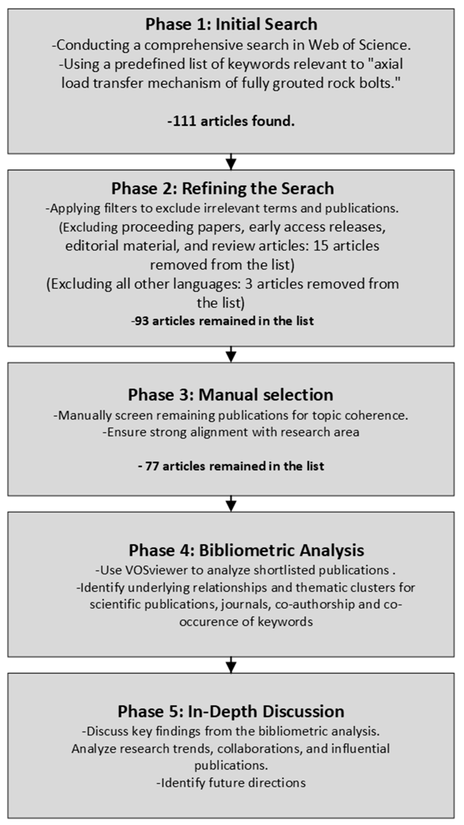
2. Materials and Methods

This systematic review paper includes five following phases (Figure 2):
  • Initial Search: This phase involves conducting a comprehensive search in the Web of Science using a predefined list of keywords relevant to the topic.
  • Refining the Search: Irrelevant terms and publications are filtered out to ensure the search results are focused and aligned with the research topic.
  • Manual Selection: To achieve the highest level of topic coherence, the remaining publications are further curated through a manual selection process, guaranteeing their strong alignment with the specific research area of the axial load transfer mechanism of FGRBS.
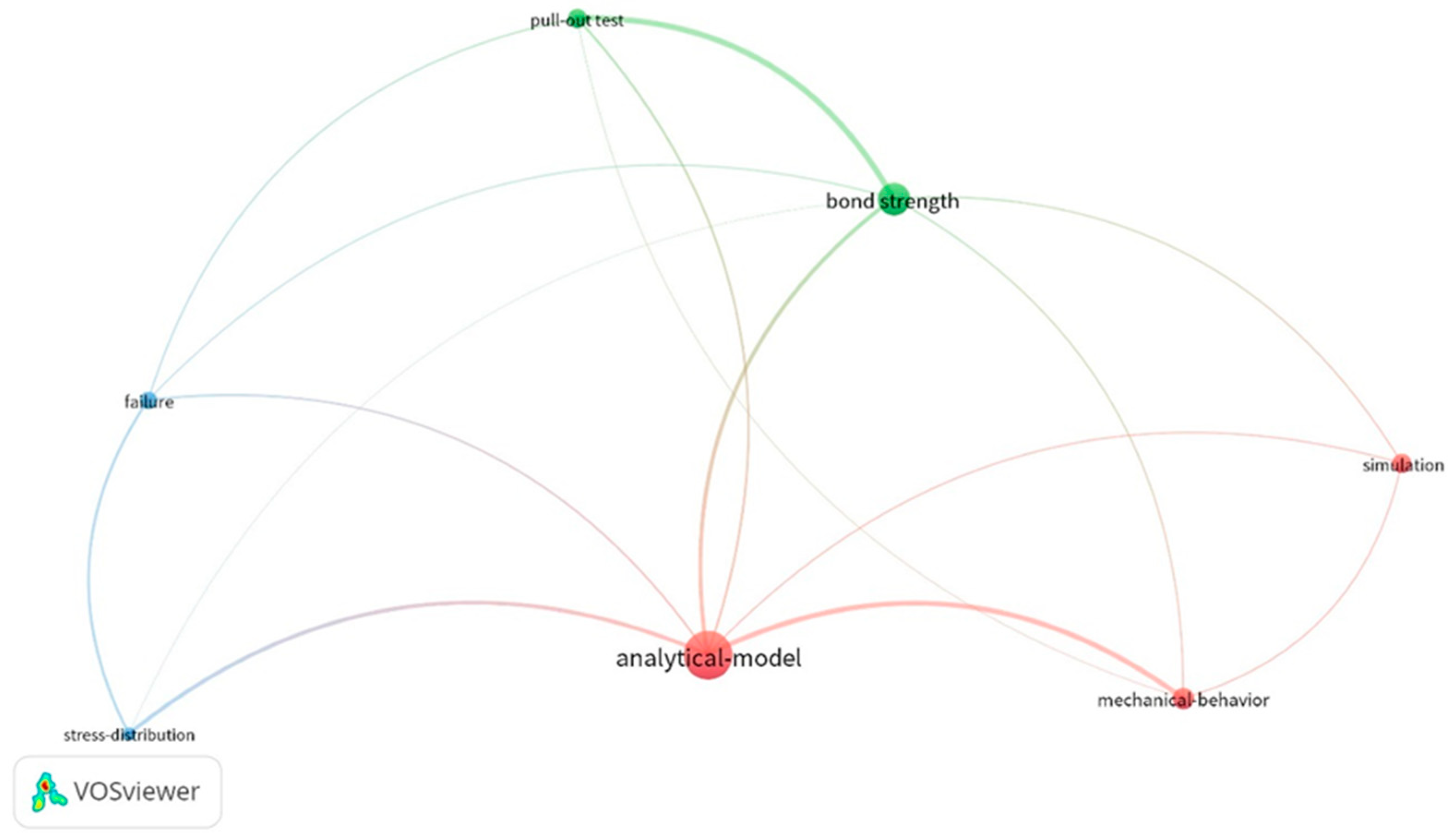
  • Bibliometric Analysis: The shortlisted publications are subjected to analysis using the VOSviewer, a bibliometric software tool. This analysis will reveal underlying relationships and thematic clusters within the selected research.
In-Depth Discussion: The final step involves a detailed discussion of the key findings gleaned from the bibliometric analysis of the reviewed publications.
  • Phase 1: Initial search
All articles on the axial load transfer mechanism of FGRBSs, published between 1988 and 2024, were searched in Web of Science’s Core Collection by searching the following keywords and Boolean operators, including “AND” and “OR”: (ALL = (fully grouted rock bolt)) AND ALL = (axial load) OR = (fully grouted rock bolt)).
This search adhered to the Preferred Reporting Items for Systematic Reviews and Meta-Analysis Protocols (PRISMA-P) guidelines [27]. The initial search yielded a total of 111 publications by using the search engine of WoS in title, abstract, and keywords.
  • Phase 2: Refining the Search
After manually checking all WoS categories to ensure all retrieved publications were relevant to the topic, the next step involved filtering the results for research quality and focus. Publications in the following categories were excluded: proceeding papers, early access releases, editorial material, and review articles. This decision aimed to concentrate on the most rigorous and influential research, typically found in peer-reviewed academic journals [28]. This filtering process removed 14 proceeding papers and 1 early access paper. Additionally, only English-language articles were considered for further analysis, excluding two papers in Chinese and one paper in Russian. Through this refinement process, the initial set of 111 publications was reduced to a more focused selection of 93 results.
  • Phase 3: Manual Selection
To further refine the selection, the titles, abstracts, and keywords of each article were manually checked and assessed to determine their alignment with the specific topic of this systematic review. For instance, Li et al. [29] presented an analytical model to understand the shear behaviour of a fully grouted cable bolt under shear loads. Although the mentioned article is one of the most cited papers in the field, it did not directly address the axial load mechanism of FGRBS. In total, 16 other articles were excluded from the list, which ultimate yielded 77 articles to conduct the systematic review of the topic.
  • Phase 4: Bibliometric Analysis
With the final selection of 77 articles, we employed bibliometric analysis to explore publication trends, prominent journals, and key research areas. VOSviewer version 1.6.20, a free, Java-based software, facilitated this analysis. VOSviewer excels at creating network maps of scientific publications, journals, researchers, and more. These networks can be built based on connections like co-authorship, co-occurrence of keywords, or citations. By analysing the resulting map and its clusters (groups of interconnected items), we gained valuable insights into the research landscape [30]. While VOSviewer was chosen for bibliometric analysis in this research, other tools such as, SciMAT v1.1.06, Bibliometrix v4.2.3, CitNetExplorer v1.0.0, Bibexcel v2016-02-20, and Pajek v5.18, can be valuable for data acquisition and initial analysis.

3. Analysis and Results

3.1. Descriptive Results

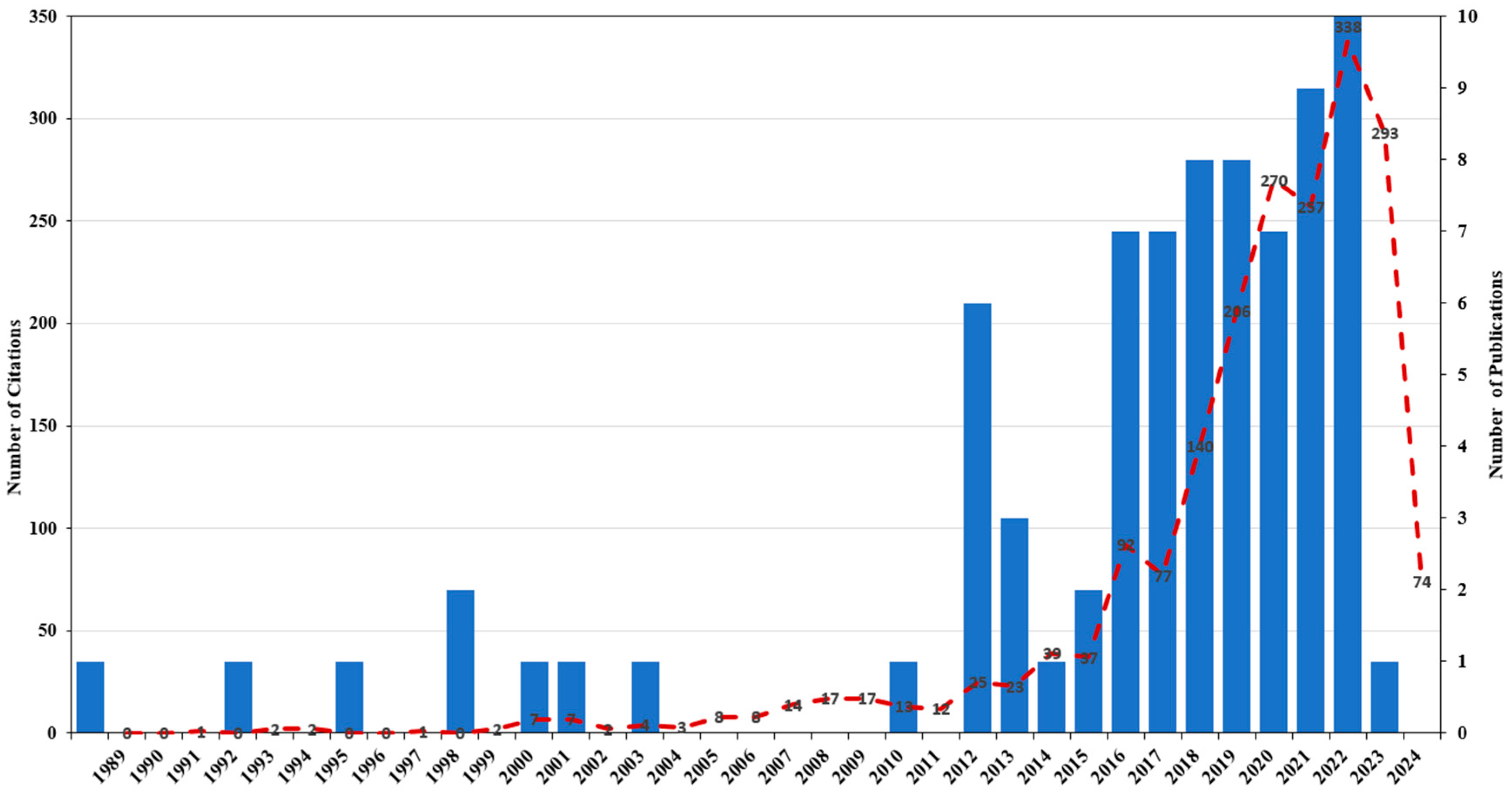
3.1.1. The Trend of Research on the Axial Load Transfer Mechanism of FGRBS

Figure 3 depicts all the publications and citations between 1988 and 2024. The first article, which investigated the axial load transfer mechanism in FGRBSs, was published by Sharma and Pande (1988) [31] in International Journal of Rock Mechanics and Mining Sciences and Geomechanics Abstracts. The analysis revealed interesting trends in publication frequency and citation patterns. Notably, there were gaps in publication output during specific periods: 1989–1992, 1994–1995, 2000, 2005–2010, and 2012. In fact, only nine articles were published prior to 2013. However, a significant surge in publications is evident from 2013 onwards, with the peak year being 2023, which saw 10 publications. This surge in interest for rock bolting can be attributed to several parameters, including technological advancements, geological considerations, and evolving mining practices. On the technological front, recent innovations in rock bolt types, grouting materials, and installation techniques have likely made these systems more attractive options. For instance, Vlachopoulos and Cruz [32] developed a novel fibre optic sensor (FOS) to monitor the axial response of FGRBSs. This innovation has the potential to improve the monitoring and performance evaluation of the FRGBSs. The shift from open-pit to underground mining presents another main reason for the increased focus on rock bolting systems. Underground environments necessitate robust ground support due to changes in in-situ stress, which can significantly impact the stability and potential failure of the surrounding rock mass [33,34]. Indeed, deep mining operations, in particular, can trigger phenomena like rock bursts and squeezing [35]. As a result, along with applying the FRGBSs, this necessitates the design and implementation of reliable bolt support systems, potentially incorporating new energy-absorbing rock bolts, such as cone bolts, D-bolts, Garford solid bolts, Roofex bolts, and Yield-Lok bolts with high load capacities and substantial deformability [9,36,37].
The first article within the dataset was cited in 1991. Interestingly, the total number of citations for publications before 2012 was only 109. Mirroring the rise in publications, the number of citations also increased significantly after 2012. By the end of the review period (2024), the articles had been cited a total of 2041 times. The years 2022 and 2023 witnessed the highest number of citations per publication, with 338 and 293 citations, respectively.
Figure 4 visually depicts the distribution of research output across different countries within the reviewed literature. Notably, China, with 41 articles, stands out as a leading contributor, publishing a significantly higher number of articles compared to countries like Australia, Canada, and Iran. The remaining countries each contributed less than five articles on the topic to the dataset.

3.1.2. Journal Outlets Leading Research on Axial Load Transfer Mechanism of FGRBSs

A review of citation patterns (bibliometric analysis) was employed to pinpoint relevant journals in this field. With a minimum threshold of one article per journal, this analysis identified 34 leading publications that addressed the axial load mechanism of FGRBSs. Table 1 presents the top ten journals with at least three articles published on this topic. Tunnelling and Underground Space takes the lead with ten articles, followed by Rock Mechanics and Rock Engineering and the International Journal of Rock Mechanics and Mining Sciences, each contributing six articles. Notably, the most cited journals mirror the top publishers, with the International Journal of Rock Mechanics and Mining Sciences garnering the most citations (576), followed by Rock Mechanics and Rock Engineering (445), and Tunnelling and Underground Space (179).

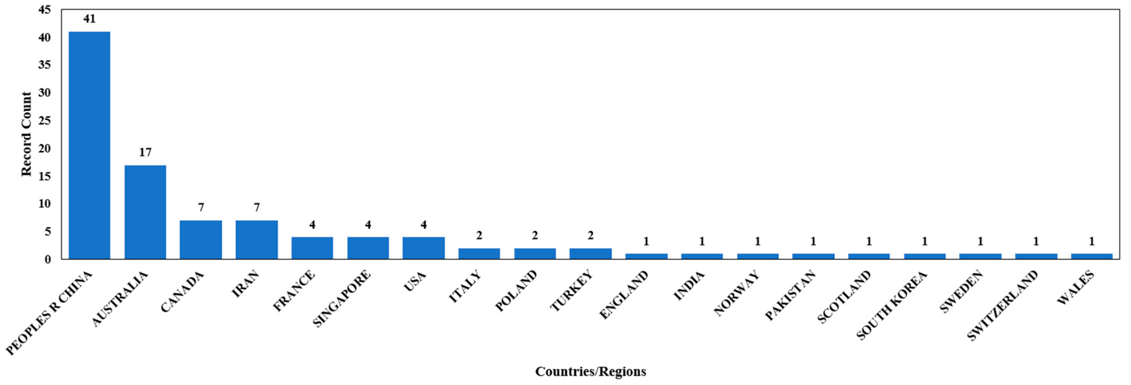
3.1.3. Institutions Leading Research on Axial Load Transfer Mechanism of FGRBS

A bibliometric analysis with co-authorship and affiliation selection revealed collaboration among 91 institutions for publications on the axial load mechanism of FGRBSs. By setting a minimum threshold of three articles per institution, a core group of 10 leading institutions emerged (Table 2). China University of Mining and Technology, University of Wollongong, and Curtin University were the most prolific publishers, contributing eight, seven, and five articles, respectively, since 1988. Interestingly, the most highly cited articles originated from the University of Wollongong, Nanyang Technological University, and the University of Adelaide.

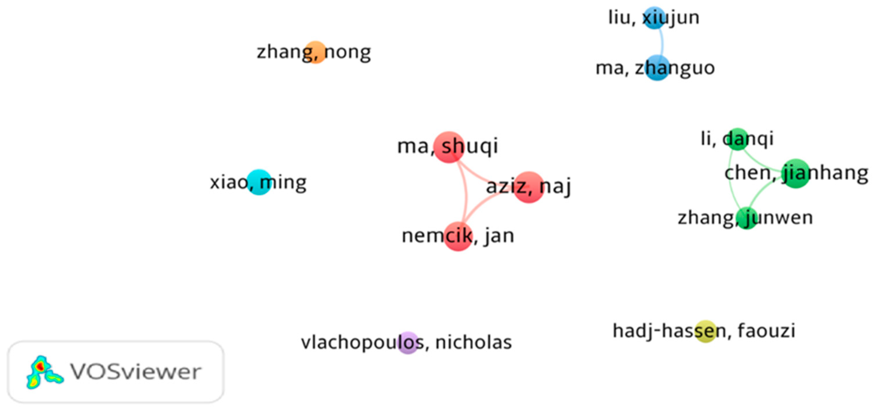
3.1.4. Researchers Leading Research on Axial Load Transfer Mechanism of FGRBSs

VOSviewer was also employed to identify key researchers in the field. Utilising co-authorship data, it revealed collaborations among 225 authors on publications related to the axial load mechanism of FGRBSs. By setting a minimum threshold of three articles per author, a group of 12 leading researchers emerged (Table 3). Notably, Shuqi Ma stands out as the most prolific researcher, having published the highest number of articles (six) and garnering the most citations (362). Naj Aziz and Jan Nemcik follow closely, each contributing five articles and receiving impressive citation counts of 320 and 318, respectively.
Figure 5 depicts seven following clusters of co-authorship among the leading researchers in the field of axial load transfer mechanisms for FGRBSs.
Red cluster: this cluster comprises Aziz, Ma, and Nemcik, whose research spans three distinct areas: numerical simulation, analytical modelling, and experimental testing (all focused on investigating the axial load transfer mechanism). Their collaboration resulted in four publications (two on numerical simulation, one on analytical modelling, and one on experimental testing) between 2013 and 2017 that have garnered a total of 262 citations. Interestingly, for their numerical simulations, they employed the finite difference method (FDM) within Flac2D software to model the non-linear bond–slip behaviour of the debonding B–G interface in FGRBSs subjected to tensile loads.
Green Cluster: This cluster comprises Li, Chen, and Zhang. Their research focuses on developing analytical approaches to evaluate the load–displacement relationship and confining pressure’s influence on the axial load transfer mechanism in FGRBSs. Notably, Chen collaborated with Zhang on three articles (cited 37 times) and Li on two separate articles (cited 52 times). Interestingly, their most recent collaboration in 2023 has already garnered 21 citations. All their models were directly calibrated from pull-out experimental tests.
Blue Cluster: This cluster includes Liu and Ma, whose research investigates the mechanical behaviour of FGRBSs under both axial and cyclic axial loads. Their collaboration resulted in four publications between 2020 and 2023, accumulating 15 citations in total.
Light Green Cluster: Hadj-Hassen, the sole researcher in this cluster, has published three articles focusing on assessing the B–G interface behaviour through laboratory pull-out tests of FGRBSs under axial load. Notably, in one publication, he and his co-authors developed an interface constitutive model. Published between 2013 and 2021, these articles have collectively received 172 citations.
Purple Cluster: Vlachopoulos, along with co-researchers, has published three articles (cited 103 times) between 2017 and 2023. All three papers utilise fibre optic technology to evaluate the performance of FGRBSs under axial load.
Orange Cluster: Zhang’s research, represented by this cluster, focuses on experimental studies of FGRBSs under axial load mechanisms. Three articles published between 2016 and 2022 explore this theme. One publication, investigating the influence of different steel tube lengths (sheaths) on axial bearing capacity, has received a particularly high number of citations (44 times).
Light-Blue Cluster: Xiao’s research, encompassing this final cluster, investigates the mechanical characteristics of FGRBSs. Four articles, published between 2017 and 2023, explore this topic. These include two numerical papers and two examining experimental tests.

3.1.5. Articles Leading Research on Axial Load Transfer Mechanism of FGRBSs

Table 4 highlights the most frequently cited articles identified within the reviewed literature. Articles receiving more than 50 citations were considered particularly influential in investigating the axial load transfer mechanism of FGRBSs. Applying this threshold, ten key papers were selected. These highly cited articles originated from a diverse range of six journals. Notably, both “International Journal of Rock Mechanics and Mining Sciences” and “Tunnelling and Underground Space Technology” emerged as leaders, publishing four and two articles, respectively. The remaining four contributing journals, ranked by citation counts, were “Construction and Building Materials”, “International Journal for Numerical and Analytical Methods in Geomechanics”, “Journal of Rock Mechanics and Geotechnical Engineering”, and “Rock Mechanics and Rock Engineering”.
As concluded from Table 4, the most highly cited articles on the axial load transfer mechanism of fully grouted rock bolts were categorised into three different methods, including (a) analytical approaches; (b) in-situ or in-laboratory pull-out tests, and (c) numerical simulation. Also, it is noteworthy that, in seven articles, pull-out tests were conducted by the researchers to verify the results of numerical simulation and analytical approaches of FGRBSs under axial load condition. However, two highly reputed articles, including those of Kılıc et al. [38] and Thenevin et al. [39], relied directly on pull-out test results. For this, Kilic et al. [38] published their articles entitled “Effect of grout properties on the pull-out load capacity of fully grouted rock bolt” in Tunnelling and Underground Space Technology, received 170 citations. This study suggested the various experimental relationships between key factors like bolt characteristics, grout behaviour (including curing time (CT), water-to-grout ratio (W/G), and uniaxial compressive strength (UCS)), and their impact on the maximum pull-out capacity of fully grouted rock bolt systems. Thenevin et al. [39] also applied the pull-out test to investigate the effects of different types of rock bolts and cable bolts, embedment length (EL), confining pressure, grouting types, and different boundary conditions on debonding mechanism at B–G interface. They also provided an extensive dataset for further studying the effects of confining pressure and embedment length on performance of FGRBSs.
In terms of analytical approaches, seven articles were published on the topic. The most cited article, published in the International Journal of Rock Mechanics and Mining Sciences by Li and Stillborg [40], garnered 294 citations. This research work presented three different analytical models focusing on the mechanical coupling between the bolt and the grout medium for rock bolting systems subjected to: (a) laboratory pull-out tests; (b) in-situ uniform rock deformation; and (c) in-situ opening of a rock joint. Their research works confirmed the previous outcomes of the pick-up length, the anchorage length, and the neutral point of the in-situ bolt. They considered three different zones, including elastic, linear behaviour of axial stress along the bolt in softening, and debonding zones. They concluded that the peak shear strength of the B–G interface was higher than shear stress values in FGRBSs. However, these values were approximately the same in fully frictionally coupled rock bolting systems. The results also reveal that the face plate could enhance the performance of the rock bolting systems. They found that the opening of the jointed rock masses may induce several axial peaks along the bolt. Their interface shear stress distribution model was subsequently developed by He et al. [41] by taking account into the constitutive model of bolt, tensile failure of the bolt shank, complete debonding B–G interface, and loss of face plate. They also used elasto-plasto (yielding–hardening) of t the steel to investigate the axial behaviour of the rock bolt. This article has already received 51 citation counts since it was published in the “Rock Mechanics and Rock Engineering” in 2021. For this, they conducted their experimental tests by considering both long and short bolts to drive full-range load displacement charts under displacement and load boundary conditions. They proposed that these charts could be used to predict several key parameters for FGRBSs, including: (a) load capacity in pull-out tests; (b) minimum bolt length required to support a loosened rock block, and (c) maximum allowable joint aperture increment. The second most cited article in analytical model published by Ma et al. [42], in Construction and Building Materials, has been cited 135 times to date. This work proposed a novel analytical model based on the bond–slip relationship, which describes of mechanical interaction at the B–G interface. The model was based on the non-linear slip distribution relationship along the B–G interface, and complete debonding mechanism. Several expressions, including shear stress distribution along the bolt and the axial load acting on the bolt and load–displacement relationship, were derived and presented. Also, they conducted a series of comprehensive pull-out tests of the short EL(s) to propose a new constitutive model for bolt–resin interface. Hyett et al. [12] published the third most cited article on the analytical approach of the axial load mechanism of FGRBSs in 1996, which received 106 citations so far. They proposed a new analytical model for load and displacement along an untensioned fully grouted rock bolting system. They compared load distribution along the bolt for two scenarios: free ends and those with a face plate. This comparison analysed how the distribution varied depending on the fracture location relative to the free face. In their research, the relationship between shear stress and slip was supposed to be linear. They have also suggested a finite difference formulation with a combination of non-linear models of a fully grouted cable bolt for investigating the debonding mechanism based on bolt and grout type. Blanco Martín et al. [43] published the fourth most cited article in analytical approach in the field. They proposed semi-empirical formula for the B–G interface under axial load. Their article has already received 96 citations. The fifth most cited paper, which was cited 63 times, was published by Jin-feng and Peng-hao [44]. Compared to previous analytical models in the field which were constant of the bond–slip relationship, they proposed a new dynamic bond–slip model to characterise bond strength (BS) along the B–G interface. They also suggested some relationships for determining the stress and strain distributions, and load–slip relationship of the bolt in pull-out tests.
Along with experimental and analytical articles, two articles on numerical modelling could obtain the highest citation counts in the field. Nemcik et al. [45] proposed a new FDM code of numerical simulation for investigating the axial load transfer mechanism of FGRBSs by using Flac2D software. For this, the non-linear bond–slip model of Ma et al. [42] was implemented. After that, Ma et al. [46] proposed a new numerical simulation for the debonding mechanism of the B–G interface based on implementing the model of tri-linear bond–slip of bolts suggested by Hyett et al. [12].
Table 4. Most frequently cited articles of axial load transfer mechanism of FGRBSs in Web of Science (1988–2024).
No.Author(s)ArticleJournal NameCitation NumberMethodMajor Findings
1Li and Stillborg [40]Analytical models for rock boltsInternational Journal of Rock Mechanics and Mining Sciences294Analytical models,
laboratory pull-out tests
Proposing three different analytical models for three different rock bolting systems subjected to: (a) laboratory pull-out tests; (b) in-situ uniform rock deformation; and (c) in-situ opening of a rock joint.
2Kilic, Yasar [38]Effect of grout properties on the pull-out load capacity of fully grouted rock boltTunnelling and Underground Space Technology170Laboratory pull-out tests,
statistical relationships,
mechanical grout characterisation
Investigating the effect of bolt profiles, including length, diameter, and bonding area, CT of the samples on the ultimate pull-out capacity; studying the influences of different grout materials and critical mechanical properties of grout, including UCS, (W/G) ratio, CT, and shear strength, on bolt bond strength (BS).
3Ma, Nemcik [42]An analytical model of fully grouted rock bolts subjected to tensile loadConstruction and Building Materials135Analytical model,
laboratory and in situ pull-out test
Proposing a new analytical model for investigating the mechanical behaviour of FGRBSs subjected to tensile load; Expressing formula of shear stress distribution along B–G interface, and axial load and load–displacement; Suggesting constitutive relationship of bolt–resin base on pull-out test. Verifying the results by comparing them with in-situ pull-out measurements.
4Hyett, Moosavi [12]Load distribution along fully grouted bolts, with emphasis on cable bolt reinforcementInternational Journal for Numerical and Analytical Methods in Geomechanics106Analytical model, numerical simulation, pull-out testsProposing a new analytical model for load and displacement along an untensioned FGRBS; Suggesting a finite difference formulation with a combination of a non-linear model of a fully grouted cable bolt for investigating the debonding mechanism based on bolt and grout type; Parametric study of BS of fully grouted cable bolts, rock mass displacement, rock mass modulus, and excavation-induced stress change.
5Blanco Martín, Tijani [43]Assessment of the bolt-grout interface behaviour of fully grouted rock bolts from laboratory experiments under axial loadsInternational Journal of Rock Mechanics and Mining Sciences96Analytical analysis,
laboratory pull-out tests
Proposing a new experimental bench to study the B–G interface debonding; investigating the effects of confining pressure, boundary conditions, bot type and profile on axial bearing capacity of full-grouted rock bolts; proposing semi-empirical formula for bot–grout interface under axial load.
6Nemcik, Ma [45]Numerical modelling of failure propagation in fully grouted rock bolts subjected to tensile loadInternational Journal of Rock Mechanics and Mining Sciences85Numerical simulation,
laboratory pull-out test,
analytical model
Developing a numerical simulation based on finite different methods (FDMs) using FLAC2D software; introducing the non-linear bond–slip relationship suggested by Ma, Nemcik [42] to FLAC software; verifying the results with experimental and analytical approaches.
7Ma, Zhao [46]A numerical model of fully grouted bolts considering the tri-linear shear bond–slip modelTunnelling and Underground Space Technology72Numerical simulation, in- situ pull-out testImplementing the model of tri-linear bond–slip of bolts suggested by Hyett, Moosavi [12] for the numerical framework; proposing a new numerical simulation for the debonding mechanism of B–G interface; parametric study; verifying the numeric results by pull-out tests.
8Thenevin, Blanco-Martín [39]Laboratory pull-out tests on fully grouted rock bolts and cable bolts: Results and lessons learnedJournal of Rock Mechanics and Geotechnical Engineering65Laboratory pull-out testInvestigating the influence of three different rock bolts, three different cable bolts, EL, confining pressure, resin, grouting materials, and different boundary conditions on the debonding mechanism at B–G interface with conducting pull-out test; providing an extensive dataset for studying the effects of confining pressure and EL on the performance of FGRBSs.
9Jin-feng and Peng-hao [44]Analytical model of fully grouted bolts in pull-out tests and in situ rock massesInternational Journal of Rock Mechanics and Mining Sciences63Analytical model, pull-out testDeveloping a new dynamic bond–slip model of fully grouted bolts under axial tension; proposing a new relationship for stress distribution, strain distribution, and load–slip relationship of the bolts; suggesting a new analytical model for in-situ rock bolt based on non-homogeneous deformation of the rock and the interaction between the bolt and surrounding rock mass; introducing a new analytical model to investigate of pretensioned and un-pretensioned rock bolts.
10He, An [41]Fully Grouted Rock Bolts: An Analytical InvestigationRock Mechanics and Rock Engineering51Analytical investigationAnalytical investigations of the performance of FGRBSs in three different scenarios, including pull-out test, suspending loosened block, and join aperture; developing analytical models of Li and Stillborg (1999) by considering the constitutive model of the bolt, tensile failure of the bolt shank, debonding B–G interface, and loss of face plate.

3.2. Research Hotspots in Axial Load Transfer Mechanism of FGRBSs

Co-occurrence keywords in VOSviewers were used to identify the research hot spot in the topic. Indeed, this feature can compute the frequency with which a given keyword occurs in the articles. After analysing all keywords and their co-occurrences, we identified 381 unique terms. Setting the minimum number of occurrences of a keyword as three, 48 keywords met the thresholds. The repetitive words such as “rock bolts”, “rockbolts”, “support”, “load”, “reinforcement”, “design”, and “fully grouted rock bolts” were omitted from the analyses. Finally, seven keywords, including pull-out test, failure, bond strength, stress-distribution, analytical model, mechanical behaviour, and simulation, can be seen in Figure 6 to show the co-occurrence mapping network of research hot spots tied to axial load transfer in FGRBSs. In the following section, the failure mechanism and the most influential parameters that can affect the axial transfer mechanism of the fully grouted rock bolting system are discussed in detail.
Pull-out test is carried out to analyse the mechanical behaviour of rock bolts [47]. To carry out the pull-out test, a rock bolt is initially inserted into a hole drilled in a rock or concrete sample and then grouted. Once the grout cures, the pull-out load is subjected to one side of the bolt which is called the loading end. Over the testing process, the load–displacement relationship is monitored utilising load cells and displacement sensors such as linear variable differential transformers (LVDTs).

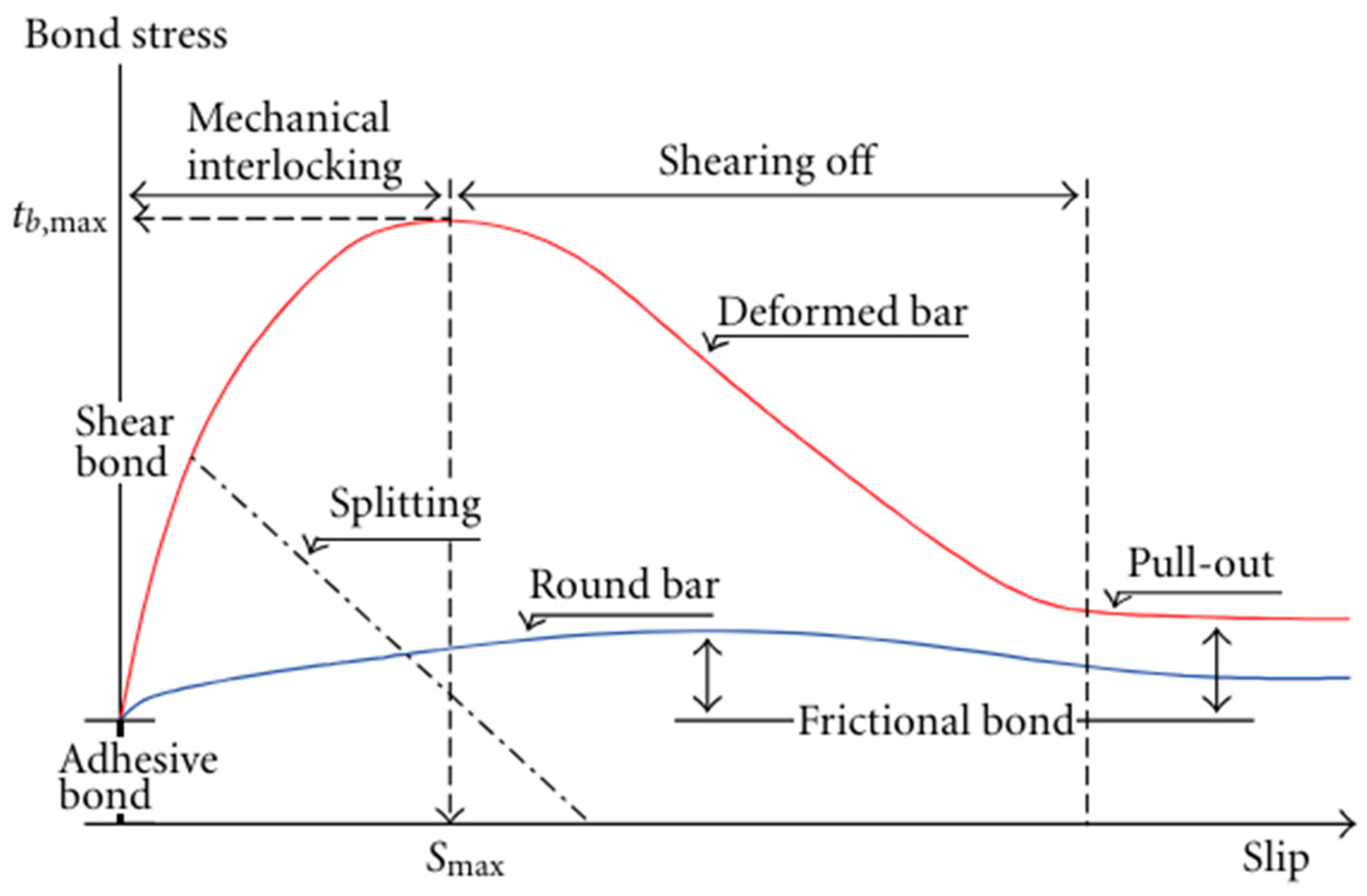
3.2.1. Failure Modes of the FGRBSs

Lutz [48] identified two fundamental failure modes for deformed reinforcing bars subject to axial loading. One is the radial splitting (dilation) of grout initiated by the wedge action of the surface ribs, while the other is the interfacial shearing of the bar surface against grout. Aydan [49] classified the failure mode of rock bolts into three main categories by conducting pull-out tests: failure along the B–G interface, failure along the R–G interface, and splitting failure of grout and surrounding rock. Many studies have confirmed that failure of FGRBSs occurs at the B–G interface [7,39,50,51]. If the rock strength is relatively weak or if the borehole diameter is relatively small, the R–G interface failure is more likely to occur. Failures at the grout–rock interface and surrounded rock are also two other failure modes in rock bolting systems [7,52,53]. However, several researchers reported that the most common failure mode occurs at the B–G interface [43,45,54,55].

3.2.2. Failure Mechanism at the B–G Interface

In FGRBSs, the mechanism governing axial load transfer between the rock bolt and the encapsulation media is known as the bond mechanism. Bond is thought to be the shearing resistance between the bolt and grout. For rock bolts, the bond can be conceptualized as the gripping action exerted by the grout along the entire EL of the deformed bar [56]. The performance of the B–G interface as the dominant failure in rock bolting systems is related to the distribution of bond stress (magnitude and direction) and bond strength of the interface. Experimental studies have identified two main interfacial failure modes in rock bolting systems including the shear-off failure (the parallel shear failure), wedge slip, and a combination of these failure modes [7,53,57,58,59]. Parallel shear failure is a cylindrical failure that occurs in smooth bars and for close-spacing ribbed bars. This failure has also been observed in the short-encapsulated laboratory pull-out tests when confining material is stiff. Zhang, Cui [60] reported a new interfacial failure mode named sheared-crush failure. The BS between a FGRB and surrounding rocks is generally recognized to be a function of three key factors: adhesion between the grout and the bolt, friction along the interface, and mechanical interlocking due to bolt ribs [61]. Nourizadeh et al. [61] found that the failure mode of FGRBSs can be impacted by the confining stresses conditions.
Figure 7 schematically illustrates the role of each strength component in the bond–slip model. Previous research studies have demonstrated that adhesion in the B–G interface does not play a crucial role in anchoring; thus, it can be neglected [42,62,63]. Prior to the system failure (peak BS), mechanical interlocking undertakes the system bond capacity. This interlocking mechanism is influenced by several factors, including the mechanical behaviour of the grout, the surrounding rock mass conditions, the level of confining stress, and the bolt surface profile [52,61,64]. Frictional components can be associated with dilational slip, shear failure of grout or rock mass, spiral displacement of bolts, and torsional unscrewing of cable bolts [12]. Moosavi, Jafari [56] pointed out that friction has a dominant effect after slip initiation.

3.3. Influential Parameters on the Axial Behaviour of FGRBSs

The performance of FGRBSs is generally governed by many key parameters which can generally be classified into three following sections: (a) the boundary conditions and the mechanical, structural, and geological properties of surrounding rock mass; (b) mechanical properties of grout, and (c) effects of bolts geometry and surface profile configuration on rock bolt performance. However, Thenevin, Blanco-Martín [39] suggested that the bolt’s profile and the strength characteristics of the bonding agent play the most significant roles among other effective factors [39]. The other influential parameters on the performance of axial transfer mechanism load of FGRBSs, which can be evaluated by conducting experimental tests, are as follows: EL, annulus thickness, hole diameter, installation procedure, cleanness of drilled hole, moisture content of the drilled hole, surface profile of the drilled hole, quality of grout pumping, and grout mixing. This process includes factors like the cleanliness of the drilled hole, its moisture content, the surface characteristics created by drilling, and the quality of both the grout mixing and pumping. It is also worth noting that, for dynamic ground conditions, yielding rock bolts can be particularly effective. These bolts, often created by modifying the geometry and surface profile of FGRBSs, can address the dual challenge of high loading capacity and significant energy absorption [20].

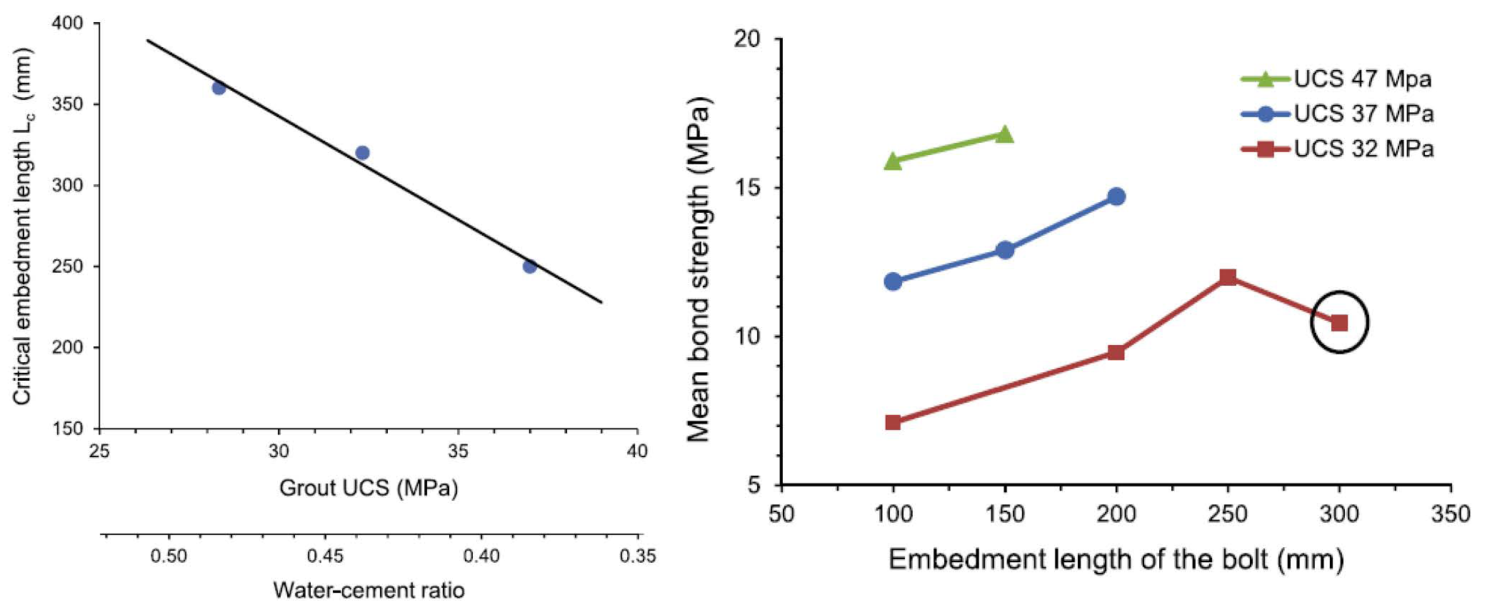
3.3.1. Effect of EL on the Axial Behaviour of FGRBSs

Several studies have explored the optimal EL in FGRBSs. Benmokrane, Chennouf [66] suggested that EL should be less than four times the bolt diameter to achieve a uniform distribution of shearing stress along the bolt. They also suggested that the axial bearing capacity increased by increasing EL from 110.6 mm to 316 mm. After that, Kilic, Yasar [67] investigated the performance of FGRBSs with embedment lengths of 200 mm and 300 mm, while Blanco Martín, Tijani [43] considered both short and long ELs in their models. The aim of considering these different ELs was to minimise free-end displacement and achieve uniform stress distribution. The length of the grouted area can also influence the behaviour of the FGRBSs under axial load conditions. Research by Ren, Yang [68] and Zou, Sneed [69] suggested that longer embedment lengths result in a five-stage load–displacement curve. When the embedment length is relatively long, the load–displacement curve shows a five-stage behaviour: (I) elastic; (II) elastic–softening, (III) elastic–softening–debonding, (IV) softening–debonding, and (V) debonding (see Figure 8). In contrast, shorter ELs may not exhibit a fully developed softening stage [70] (see Figure 9). Li, Kristjansson [71] carried out a series of pull-out tests and found that the W/G ratio can affect the critical EL. They quantified the critical EL as 250 mm, 320 mm, and 360 mm for W/G ratios of 40%, 46%, and 50%, respectively (Figure 10). A linear relationship between EL and W/G ratios was proposed. Additionally, it was observed that the BS is dependent on EL, exhibiting a linear proportionality to the UCS of the grout. To evaluate the influence of EL on BS, Yu, Zhu [72] performed a series of pull-out tests on FGRBSs with ELs ranging from 250 mm to 1600 mm. Their results indicate a positive correlation between EL and BS, with higher ELs leading to enhanced BS and consequently higher axial bearing capacity. The tests also revealed distinct behavioural changes based on EL. Rock bolts exhibited elastic behaviour for ELs less than 850 mm. When the EL reached 860 mm, a yielding stage was observed for the first time. Notably, with an EL of 1500 mm, the rock bolts displayed a complete stress–strain response, encompassing elastic ascent, yielding, and hardening stages without rupture. Finally, necking, a localized reduction in bolt diameter, was observed in samples with the longest EL of 1600 mm. Høien, Li [73] suggested that the critical EL could be determined based on the sum of three following parameters: (a) the elastic deformation length; (b) a plastic deformation length; and (c) a completely deboned length.

3.3.2. Effects of Boundary Conditions and Rock Mass on the Axial Performance of FGRBSs

The strength of the rock mass can heavily affect the failure mechanism of the FGRBSs. In the soft medium (rocks), the primary failures tend to occur in the R–G interface. Conversely, strong rock sees failures predominantly in the B–G interface. Along with the pressure of internal confinement, the critical role of in-situ stress, the pressure exerted by the surrounding rock has also been thoroughly acknowledged [13,31,41,48]. Indeed, relaxation of in-situ stress can lead to a substantial decrease in the anchoring effectiveness of the FGRBS, particularly at the rock–grout interface. It is noteworthy to mention that, in the very soft rocks, the axial stress along the bolt decreases due to the uniform distribution of shear stress along the bolt [47]. The radial dilation is induced by the axial slip of deformed rock bolts. However, the extent of dilational failure can be limited by the confining stress applied to the rock mass. Moreover, a higher normal stiffness of the rock mass serves to further restrict the incidence of dilation. Unlike soft rocks or intensively jointed and cracked hard rocks, in hard rocks without effective joints, dilation may increase the radial confining stress, resulting in the high bond capacity of the fully grouted rock bolt. Tepfers [74] suggested two types of cracks: cone-shaped cracks, and longitudinal splitting cracks, which resulted in debonding during pull-out of steel rebar bolts inside the concrete. The development cracking pattern depended on surrounding concrete and the rebar geometry. The Yi, Wang [75] studied the effect of concrete compressive strength and rock mass integrity on performance of anchored rock bolts. They concluded that the failure modes of the joint rock are influenced by the rock mass integrity (Kv), which can be categorised as follows: (a) structural failure with longitudinal cracks; (b) joint surface failure with rapid crack development around the prefabricated joints, resulting in joint surface failure, and (c) disintegrate failure with developing cracks near the joint surface, resulting disintegrated failure of joint rock (Figure 11).
Three modes of boundary conditions can be applied in laboratory pull-out tests, including constant normal stiffness (CNS), constant normal load (CNL), and no boundary conditions. Constant radial stiffness can better reflect the actual field conditions because shear dilation is inhibited by surrounding rock mass [58]. Hyett, Bawden [58] studied the influence of radial stiffness on the axial and shear behaviour of cable bolts by conducting a series of experimental split–pipe tests using various materials, including PVC, aluminium, and steel pipes. Their findings suggested a correlation between radial stiffness and failure mechanisms, with higher stiffness leading to distinct failure modes and ultimately, a greater axial load-bearing capacity. Moosavi, Jafari [56] carried out a series of pull-out tests under constant radial confining stress using modified triaxial Hoek cell to quantify the influence of confining pressure arising from frictional dilation. The confining pressure ranged from 1.3 to 7.5 MPa. The results reveal that, at lower confining pressures, cracks fully develop on the outer surface of the specimens, indicating slip accompanied by dilation. Blanco Martín et al. [54] observed that radial fractures became more prominent at lower confining pressures. Zhang, Cui [60] reported similar trends, noting that dilational failure is the dominant mode at low normal stresses (0.5 MPa). However, as the normal stress increases to 2 MPa, shear-off failure becomes the primary mechanism. At even higher stresses (6 MPa), they also observed the coexistence of both shear-off and shear-crush failure modes. Li, Li [76] proposed an analytical model to simulate the load–displacement behaviour of FGRBSs under axial loading. However, the model’s validity was limited to scenarios with constant confining pressure, typically applied in Hoek cells or biaxial cells. Yu, Zhu [77] found that increasing the confining pressure resulted in decreasing rock mass quality (Q) values, and the bond quality of rock bolts decreased, under the same pull-out loads. However, the Q values were increased by increasing the confining pressure if there were no pull-out loads (Figure 12).

3.3.3. Effects of Grout Mechanical Characteristics on the Axial Performance of FGRBSs

In general, grout acts as an interface between the retaining system, such as rock and cable bolts, and surrounding rocks with their loading transfer abilities. As a result, the performance of FGRBSs heavily depends on the quality and mechanical behaviours of the grouts. Moreover, these behaviours are controlled by some significant parameters, such as W/G ratios, CT, additives, proper mixing of grout components, and the type of grouts. As a result, certain researchers focused on investigating the impact of the strength properties of grouts [10,38,43,58,66,78,79,80,81,82,83,84,85,86,87,88,89,90]. For instance, Hyett, Bawden [58] found that the bearing capacity of the fully grouted cable bolting system increased by 50 to 70% in lower W/G ratios under 40%. This is due to the fact that lower (W/G) ratios presented higher mechanical characteristics including UCS and Young’s modulus. Benmokrane, Chennouf [66] performed a pull-out test to find the effects of different types of cementitious grouts on grouted anchors. By comparing the results, they found that the bond stiffness and essentially interfacial BS depended on the mechanical properties of the grout. It was concluded that the bond stiffness values in threaded bars are higher than those of stranded cables. Kilic, Yasar [38] investigated the effect of grout properties on the axial bearing capacity of FGRBSs. They found that the W/G ratio should not be of more than 40% (wt). The lowest values of UCS and shear strength of grout ( τ g ) were achieved in grout mixtures with higher ratios of W/G. Aziz et al. (2014) proposed methods for preparing and testing different properties of grout and resins such as, UCS, Elastic modulus (E), τ g , creep, and rheological properties. Li, Kristjansson [71] reported the water content as an influential factor affecting the critical embedment length. Mirza, Aziz [81] investigated the mechanical behaviour of two types of grouts mainly used in Australia, Jennmar Bottom-Up 100 (BU-100), and Orica Stratabinder HS. For this purpose, a series of compression tests were conducted on 50 mm cube samples, which had been cured over a period of 1 to 28 days. The results show that the UCS of both grouts increased over curing time. The experimental creep testing results from samples cured for 42 days in the study conclude that there is no notable discrepancy in the creep behaviour of those grouts. Aziz, Majoor [80] investigated the effects of W/G ratio on UCS of commercial grout products. The results show a 43% reduction in UCS once the W/G ratio increased from 28% to 42%. Mirzaghornanali [83] examined the influence of sample size and curing time on the strength characteristics of two commercially available encapsulation grouts. The findings reveal a progressive increase in UCS over time. Additionally, it was observed that the UCS of samples cast in smaller moulds is 1.5 times higher than that of larger samples. Interestingly, four point flexural test results indicate that bending resistance decreases with the CT. Chang, Wang [91] reported a direct interrelationship between the grout’s UCS and BS. An increase in the BS from 3.8 to 11.5 MPa is reported as the UCS of the grout increased from 30 MPa to 60 MPa. Experimental and field studies also showed that the optimum annulus thickness is in the range of 2–7 mm and delivers the best load transfer interaction.
Teymen [86] investigated the bonding performance of FGRBSs encapsulated by different admixtures, including formulations incorporating silica fume, fly ash (FA), blast furnace slag, perlite, metakaolin, and other minerals. Pull-out samples, each measuring 150 mm in length, underwent testing at five different CTs ranging from 1 to 90 days. The author discovered that incorporating additives can enhance the mechanical properties of the grout, resulting in an improvement of 5% to 12% in the axial load-bearing capacity of the FGRBS. Kim, Rehman [92] performed a series of pull-out tests considering the settling times of cement–grout rock bolts for immediate support applications. The tests were conducted for moderate and weathered rocks for various CTs including 12, 24, and 36 h. They concluded that there was a positive correlation between the ultimate pull-out capacity and the settling time of FGRBSs. Yu, Zhu [72] indicated that an increase in the UCS of the encapsulation material enhances the axial load bearing capacity and energy absorption of FGRRBS. Nourizadeh, Williams [93] studied the effects of W/G ratios and CT on the ultimate pull-out capacity of FGRBSs. The study revealed that the ultimate bearing capacity increases with CT and decreases with lower W/G ratios. Entezam, Jodeiri Shokri [84] showed that incorporation of a small amount of FA into the grout mixture can enhance the UCS of grout and consequently the axial bearing capacities of the system.

3.3.4. The Interaction between Grouting Process and Rock Mass Condition

The quality of rock mass can heavily affect grouting process. For instance, weak and fractured rocks can pose challenges to achieving optimal grouting results. Studies have shown that voids and fractures conditions within the rock mass can contribute to significant grout loss [11,94]. Additionally, even non-continuous discontinuities can play as open fractures, leading to inaccurate predictions of both hydraulic conductivity and grout flow [95]. Also, it is suggested to apply a resin-grouted rock bolt in rocks without widely open fractures or discontinuities [96]. To address these issues in situations where internal connections within the rock may impede grout flow, innovative techniques like forensic excavation of rock mass (FERM) could prove valuable in detecting these problematic connections [97].
Along with rock mass conditions, other several key parameters, such as the grouting layer and grouting pressure, significantly impact the quality of the grouting reinforcement system [98]. For instance, the fractures’ sizes gradually decrease by increasing the depth of the grouting procedure. As a result, by applying moderate pumping pressure, the grout properly spreads in the voids, which results in suitably compacting the surrounded rock mass. Conversely, applying high pumping pressure allows for the grout to not only penetrate even microfractures but also potentially induce new fractures in the rock itself, achieving a more comprehensive “fracture grouting” effect [98].

3.3.5. Effects of Bolts Geometry and Surface Profile Configuration on FGRBS Performance

System splitting is entirely absent with round rebars. Thus, the geometric design of ribs, including their height, width, angle, spacing, and orientation, plays a crucial role in the capacity of FGRBSs (Figure 13).
The surface profile of the ribs dictates the width of the shear zone and the fracture angle within the encapsulation medium. These factors hold greater significance for FGRBSs compared to conventional steel rebars used in civil engineering applications. This is primarily due to the exposure of FGRBSs to significantly higher dynamic loads [99]. Nie, Zhao [57] applied discontinuous deformation analysis (DDA) numerical modelling to investigate the effect of rib on the BS. They demonstrated a positive correlation between maximum BS and rib face angle within the range of 30–90°. Conversely, rib face angles below 30° were found to be ineffective in enhancing BS. It was also stated that larger rib spacing had a possible negative correlation with bond stiffness. Studies conducted by Aziz and Webb [63] and Aziz, Jalalifar [100] demonstrated that BS and axial load capacity increase with the ribs’ height and rib spacing. After several pull-out and push tests, Aziz, Jalalifar [99] found that the axial bearing capacity would be highest where the profile spacing is 37.5 mm. Ito, Nakahara [101] attempted to visualise the failure patterns of rock bolts with different surface profiles using an X-ray CT scanner. The authors concluded that the failure mechanism of FGRBSs is dependent on the specific design of the ribs’ shape and the bolt’s lugs. Cao et al. [53] highlighted the dependence of the optimal bolt profile configuration in FGRBSs on both the mechanical characteristics of grout and confining stress. Tao, Chen [102] performed push and pull-out tests to investigate the influence of rib spacing on transferring the loading mechanism. The study examined the FGRBSs with various spacing of 12, 24, 36, and 48 mm, encapsulated in steel and concrete. The results show a 23.5% increase in the maximum peak loads increased by large rib spacing when confined in the steel. Interestingly, no significant difference in peak loads was observed between large and small rib spacings for FGRBSs encased in concrete. However, in both confinements, energy absorption in large-spacing samples was higher than in the small-spacing samples. Yokota, Zhao [103] attempted to examine the effect of the bolt configuration on the bolt’s mechanism by seeking crack initiation and propagation. For this, the FGRBS was simplified as a typical joint. Experiment results revealed that rib angle has little influence on crack initiation and propagation and peak shear strength; however, as the rib angle decreases, shear stiffness slightly increases. Yokota, Zhao [104] studied the influence of various factors of a rock bolt’s profile, such as rib angle, mortar thickness, rib space, and rib shape on axial behaviour of rock bolting systems by conducting DDA and experimental methods. After conducting several laboratory pull-out tests, Motallebiyan, Nourizadeh [105] found that the axial bearing capacity of FRGBSs has a positive correlation with the rib spacing.

3.4. Summary of Review Findings

Table 5 summarises the significant outcomes from the systematic review of the axial load transfer mechanism in FGRBSs. A citation analysis revealed that the most relevant publications come from three journals: Tunnelling and Underground Space Technology (ten articles), Rock Mechanics and Rock Engineering (six articles), and the International Journal of Rock Mechanics and Mining Sciences (six articles). These articles have garnered a total of 1200 citations. Co-authorship analysis identified China University of Mining and Technology, University of Wollongong, Curtin University, and Nanyang Technological University as leading institutions in this field. Notably, a strong collaboration exists between Aziz, Ma, and Nemcik, with four co-authored publications accumulating 262 citations. These publications encompass all three key research areas: numerical simulation, analytical modelling, and experimental testing all focused on understanding the axial load transfer mechanism.

4. Conclusions and Further Directions

Rock bolting systems, particularly FGRBSs, are essential methods in mining, civil, and geotechnical engineering. They enhance rock mass stability, minimise deformation, and contribute to improved safety, budget, and faster project timelines. Regardless of the type, rock bolting systems develop forces in response to rock movement. The failure of FGRBSs can occur in different modes; however, bond failure at the B–G interface is widely recognised as the predominant failure mechanism. Understanding the axial load transfer mechanism forms the foundation for investigating interfacial shear behaviour in FGRBSs. To date, numerous laboratory tests have been conducted to characterise the behaviour of the B–G interface. The results indicated that the system’s interfacial and axial response depends on the FGRBS’s mechanical and geometrical characteristics, mechanical characteristics of grout, geo-mechanical properties of the rock mass, and boundary conditions. Amongst these factors, bolt surface profile and grout composition and mixture can be engineered and optimised for the preferable performance. The systematic reviews revealed that the effect of these factors has been investigated individually, e.g., the load–displacement behaviour, debonding capacity, or fracture propagation. Findings from experimental studies demonstrate that bolt surface configuration, e.g., rib angle, rib spacing, and rib width, impacts the axial behaviour of FGRBSs. The systematic review showed that there is a lack of understanding of the axial behaviour of FGRBSs in the corrosive environments. The authors found no research investigating the effect of preventative methods, such as sheathing, on the axial load mechanism of FGRBSs. The main challenge of applying such a preventative technique on FGRBSs is ensuring effective load transfer between the bolt, the grout annuli, and the rock or soils. Along with applying sheath, or sleeves, applying the fully grouted fibre rock bolts is another option in corrosive environments. The shearing mechanism of fully grouted fibreglass rock bolting systems and fully grouted sheathed rock bolts was investigated in a few identified research works. However, to the authors’ best knowledge, few systematic studies have investigated the effect of using sheaths or fiberglass dowels on the axial load transfer mechanism of fully grouted bolts. As a result, it is recommended to focus on conducting future research works on developing experimental, analytical, and numerical analyses to contribute to a better understanding of the axial loading transfer mechanism in fully grouted sheathed/fibreglass rock bolts. Also, as discussed in the article, along with the importance of pull-out testing for measuring axial bearing capacity in FGRBSs which is well-established in the literature, machine learning (ML) and artificial intelligence (AI) are the other options which can offer promising approaches to accurately forecast the axial transfer mechanism within the FGRBSs. This could empower researchers and engineers to proactively identify potential reinforcement failures, leading to significant gains in research efficiency. Notably, ML methods hold great potential to enhance rock bolting research, particularly in areas directly related to the axial bearing capacity of FGRBSs. However, further research is necessary to address challenges associated with data availability, privacy concerns, and the development of high-accuracy models with limited computational resources.

Author Contributions

Conceptualization, B.J.S., A.M., H.N., K.M., W.K., N.A., S.E. and A.E.; methodology, B.J.S., A.M., H.N., S.E. and A.E.; software, B.J.S., S.E. and A.E.; validation, B.J.S., A.M., H.N., S.E. and A.E.; formal analysis, B.J.S., A.M., H.N., K.M., W.K., N.A., S.E. and A.E.; investigation, B.J.S., A.M., H.N., K.M., W.K., N.A., S.E. and A.E.; resources, B.J.S., A.M., H.N., K.M. and W.K.; data curation, B.J.S., A.M., H.N., K.M., W.K., N.A., S.E. and A.E.; writing—original draft preparation, B.J.S., A.M., H.N. and S.E.; writing—review and editing, B.J.S., A.M., H.N., S.E. and A.E.; visualization, B.J.S., A.M., H.N., S.E. and A.E. All authors have read and agreed to the published version of the manuscript.

Funding

This research received no external funding.

Conflicts of Interest

The authors declare no conflict of interest.

Nomenclature

SymbolsShort definition
AIArtificial Intelligence It can perform tasks typically requiring human-like abilities like learning, reasoning, and problem-solving.
B–G Bolt–grout interfaceContact zone between rock bolt and surrounding grout where load transfer occurs [61].
BSBond strength (MPa)Shearing resistance between the bolt and grout [61].
BU-100Bottom-Up 100 An Australian grout type in which grouting is injected from the bottom of the borehole to the top.
CMCContinuously mechanically coupled anchoring techniqueThis technique is a continuous mechanical connection between the bolt and the rock mass [1].
CNLConstant normal load Under CNL conditions, the normal stress remains constant, and rock joints are free to dilate [106,107].
CNSConstant normal stiffness CNS conditions involve varying normal stiffness, where joint dilation is partially or fully restricted by the surrounding rock mass [107].
CFCContinuously frictionally coupled anchoring techniqueThis technique relies on frictional coupling between the bolt and the rock surface [1].
CTCuring time (day, hour, min, sec)Critical period for grout to harden and form a strong bond with rock mass [108].
DMFCDiscretely mechanically/frictionally coupled anchoring techniqueOne of the rock bolts’ type have discrete mechanical or frictional connections [1].
EElastic modulus (MPa)Material’s stiffness, indicating its resistance to elastic deformation under stress.
ELEmbedment length (m)Length of the bolt that is encased and bonded with grout within the rock mass [73].
FAFly ash An organic matter within the coal [109].
FDM Finite different method
FGRBSFully grouted rock bolting system A type of rock bolting system [8]
FOS Fibre optic sensor
LVDTLinear variable differential transformerAn electromechanical transducer that converts linear motion into an electrical signal using a moveable ferromagnetic core and multiple coils [47].
MLMachine learning The method empowers computers to learn from data, enabling them to make predictions or decisions without explicit programming.
R–G Rock–grout (R–G) interfaceWhere the load transfers from bolt to the rock mass by grout [61].
Qrock mass quality (%)Refers to how well rock will hold together under stress and excavation [110].
UCSUniaxial compressive strength (MPa)The maximum stress a rock or material can withstand when squeezed from one direction.
W/GWater-to-grout ratio (%)Refers to the proportion of water mixed with cementitious grout [38].
τ g Shear strength of grout (MPa)The maximum resistance it offers against shear forces before failure occurs [47].

References

  1. Windsor, C.R. Rock reinforcement systems. Int. J. Rock Mech. Min. Sci. 1997, 34, 919–951. [Google Scholar] [CrossRef]
  2. Schach, R.; Garshol, K.; Heltzen, A. Rock Bolting: A Practical Handbook; Pergamon: Oxford, UK, 1979; p. 92. [Google Scholar]
  3. Lang, T.A.; Bischoff, J.A.; Wagner, P.L. A program plan for determining optimum roof bolt tension. In Theory and Application of Rock Reinforcement Systems in Coal Mines; U.S. Department of Energy Office of Scientific and Technical Information: Oak Ridge, TN, USA, 1979. [Google Scholar]
  4. Bolstad, D.; Hill, J. Bureau of Mines rock bolting research. In Proceedings of the International Symposium on Rock Bolting, Abisko, Sweden, 28 August–2 September 1983; pp. 313–320. [Google Scholar]
  5. Rasekh, H. The Shear Performance of Cable Bolts in Experimental, Numerical and Mathematical Studies. In School of Civil, Mining and Environmental Engineering; University of Wollongong: Wollongong, Australia, 2017. [Google Scholar]
  6. Thompson, A.G.; Villaescusa, E.; Windsor, C.R. Ground Support Terminology and Classification: An Update. Geotech. Geol. Eng. 2012, 30, 553–580. [Google Scholar] [CrossRef]
  7. Cao, C.; Nemcik, J.; Aziz, N.; Ren, T. Failure modes of rockbolting. In Proceedings of the 12th Coal Operators’ Conference, Wollongong, Australia, 16 February 2012; pp. 135–173. [Google Scholar]
  8. Frenelus, W.; Peng, H.; Zhang, J. An Insight from Rock Bolts and Potential Factors Influencing Their Durability and the Long-Term Stability of Deep Rock Tunnels. Sustainability 2022, 14, 10943. [Google Scholar] [CrossRef]
  9. Li, C.C. A new energy-absorbing bolt for rock support in high stress rock masses. Int. J. Rock Mech. Min. Sci. 2010, 47, 396–404. [Google Scholar] [CrossRef]
  10. Nourizadeh, H.; Mirzaghorbanali, A.; McDougall, K.; Jeewantha, L.H.J.; Craig, P.; Motallebiyan, A.; Jodeiri Shokri, B.; Rastegarmanesh, A.; Aziz, N. Characterization of mechanical and bonding properties of anchoring resins under elevated temperature. Int. J. Rock Mech. Min. Sci. 2023, 170, 105506. [Google Scholar] [CrossRef]
  11. Zou, D. Ground Reinforcement and Support. In Theory and Technology of Rock Excavation for Civil Engineering; Springer: New York, NY, USA, 2017; pp. 579–637. [Google Scholar] [CrossRef]
  12. Hyett, A.J.; Moosavi, M.; Bawden, W.F. Load Distribution Along Fully Grouted Bolts, with Emphasis on Cable Bolt Reinforcement. Int. J. Numer. Anal. Methods Geomech. 1996, 20, 517–544. [Google Scholar] [CrossRef]
  13. Li, C.C. Principles of rockbolting design. J. Rock Mech. Geotech. Eng. 2017, 9, 396–414. [Google Scholar] [CrossRef]
  14. Luga, E.; Periku, E. A pioneer in-situ investigation on the bearing capacity and failure causes of real scale fully grouted rockbolts. Constr. Build. Mater. 2021, 310, 124826. [Google Scholar] [CrossRef]
  15. Vlachopoulos, N.; Cruz, D.; Tatone, B.S.A.; Lisjak, A.; Mahabadi, O.K.; Forbes, B.; Carrapatoso, C. The Performance of Axially Loaded, Fully Grouted Rock Bolts Based on Pull-Out Experiments Utilizing Fiber Optics Technology and Associated Numerical Modelling of Such Support Elements. Geotech. Geol. Eng. 2019, 38, 1389–1407. [Google Scholar] [CrossRef]
  16. Ma, S. Load transfer mechanism of fully encapsulated rockbolts. In School of Civil, Mining, and Environmental Engineering; University of Wollongong: Wollongong, Australia, 2014. [Google Scholar]
  17. Song, G.; Li, W.; Wang, B.; Ho, S.C. A Review of Rock Bolt Monitoring Using Smart Sensors. Sensors 2017, 17, 776. [Google Scholar] [CrossRef]
  18. Jalilfar, H. A new approach in determining the load transfer mechanism in fully grouted bolts. In School of Civil, Mining and Environmental Engineering—Faculty of Engineering; University of Wollongong: Wollongong, Australia, 2006. [Google Scholar]
  19. Skrzypkowski, K. The Influence of Room and Pillar Method Geometry on the Deposit Utilization Rate and Rock Bolt Load. Energies 2019, 12, 4770. [Google Scholar] [CrossRef]
  20. Skrzypkowski, K.; Korzeniowski, W.; Zagórski, K.; Zagórska, A. Adjustment of the Yielding System of Mechanical Rock Bolts for Room and Pillar Mining Method in Stratified Rock Mass. Energies 2020, 13, 2082. [Google Scholar] [CrossRef]
  21. Skrzypkowski, K. An Experimental Investigation into the Stress-Strain Characteristic under Static and Quasi-Static Loading for Partially Embedded Rock Bolts. Energies 2021, 14, 1483. [Google Scholar] [CrossRef]
  22. Ma, S.; Aziz, N.; Nemcik, J.; Mirzaghorbanali, A. The effects of installation procedure on bond characteristics of fully grouted rock bolts. Geotech. Test. J. 2017, 40, 20160239. [Google Scholar] [CrossRef]
  23. Windsor, C.; Thompson, A. Rock reinforcement-technology, testing, design and evaluation. Compr. Rock Eng. Princ. Pract. Proj. 1993, 4, 451–484. [Google Scholar]
  24. Littlejohn, G.; Bruce, D. Rock-anchors state of the art. Des. Ground Eng. Part1 1975, 8, 25–78. [Google Scholar]
  25. Harris, J.D.; Quatman, C.E.; Manring, M.M.; Siston, R.A.; Flanigan, D.C. How to Write a Systematic Review. Am. J. Sports Med. 2013, 42, 2761–2768. [Google Scholar] [CrossRef]
  26. Wright, R.W.; Brand, R.A.; Dunn, W.; Spindler, K.P. How to Write a Systematic Review. Clin. Orthop. Relat. Res. 2007, 455, 23–29. [Google Scholar] [CrossRef] [PubMed]
  27. Moher, D.; Shamseer, L.; Clarke, M.; Ghersi, D.; Liberati, A.; Petticrew, M.; Shekelle, P.; Stewart, L.A.; Group, P.-P. Preferred reporting items for systematic review and meta-analysis protocols (PRISMA-P) 2015 statement. Syst. Rev. 2015, 4, 1. [Google Scholar] [CrossRef]
  28. Santos, R.; Costa, A.A.; Grilo, A. Bibliometric analysis and review of Building Information Modelling literature published between 2005 and 2015. Autom. Constr. 2017, 80, 118–136. [Google Scholar] [CrossRef]
  29. Li, X.; Nemcik, J.; Mirzaghorbanali, A.; Aziz, N.; Rasekh, H. Analytical model of shear behaviour of a fully grouted cable bolt subjected to shearing. Int. J. Rock Mech. Min. Sci. 2015, 80, 31–39. [Google Scholar] [CrossRef]
  30. Eck, N.J.; Waltman, L. Manual for VOSviewer Version 1.6.20; Universiteit Leiden and CWTS Meaning Metrics: Leiden, The Netherlands, 2023; p. 55. [Google Scholar]
  31. Sharma, S.G.; Pande, G.N. Stability of rock masses reinforced by passive, fully-grouted rock bolts. Int. J. Rock Mech. Min. Sci. Geomech. Abstr. 1988, 25, 273–285. [Google Scholar] [CrossRef]
  32. Vlachopoulos, N.; Cruz, D.; Forbes, B. Utilizing a novel fiber optic technology to capture the axial responses of fully grouted rock bolts. J. Rock Mech. Geotech. Eng. 2018, 10, 222–235. [Google Scholar] [CrossRef]
  33. Ranjith, P.G.; Zhao, J.; Ju, M.; De Silva, R.V.S.; Rathnaweera, T.D.; Bandara, A.K.M.S. Opportunities and Challenges in Deep Mining: A Brief Review. Engineering 2017, 3, 546–551. [Google Scholar] [CrossRef]
  34. Fairhurst, C. Some Challenges of Deep Mining. Engineering 2017, 3, 527–537. [Google Scholar] [CrossRef]
  35. Yokota, Y.; Zhao, Z.; Nie, W.; Date, K.; Iwano, K.; Koizumi, Y.; Okada, Y. Development of a new deformation-controlled rock bolt: Numerical modelling and laboratory verification. Tunn. Undergr. Space Technol. 2020, 98, 103305. [Google Scholar] [CrossRef]
  36. Hao, Y.; Wu, Y.; Ranjith, P.G.; Zhang, K.; Hao, G.; Teng, Y. A novel energy-absorbing rock bolt with high constant working resistance and long elongation: Principle and static pull-out test. Constr. Build. Mater. 2020, 243, 118231. [Google Scholar] [CrossRef]
  37. Zhao, X.; Zhang, S.; Zhu, Q.; Li, H.; Chen, G.; Zhang, P. Dynamic and static analysis of a kind of novel J energy-releasing bolts. Geomat. Nat. Hazards Risk 2020, 11, 2486–2508. [Google Scholar] [CrossRef]
  38. Kilic, A.; Yasar, E.; Celik, A.G. Effect of grout properties on the pull-out load capacity of fully grouted rock bolt. Tunn. Undergr. Space Technol. 2002, 17, 355–362. [Google Scholar] [CrossRef]
  39. Thenevin, I.; Blanco-Martín, L.; Hadj-Hassen, F.; Schleifer, J.; Lubosik, Z.; Wrana, A. Laboratory pull-out tests on fully grouted rock bolts and cable bolts: Results and lessons learned. J. Rock Mech. Geotech. Eng. 2017, 9, 843–855. [Google Scholar] [CrossRef]
  40. Li, C.; Stillborg, B. Analytical models for rock bolts. Int. J. Rock Mech. Min. Sci. 1999, 36, 1013–1029. [Google Scholar] [CrossRef]
  41. He, L.; An, X.M.; Zhao, Z.Y. Fully Grouted Rock Bolts: An Analytical Investigation. Rock Mech. Rock Eng. 2014, 48, 1181–1196. [Google Scholar] [CrossRef]
  42. Ma, S.; Nemcik, J.; Aziz, N. An analytical model of fully grouted rock bolts subjected to tensile load. Constr. Build. Mater. 2013, 49, 519–526. [Google Scholar] [CrossRef]
  43. Blanco Martín, L.; Tijani, M.; Hadj-Hassen, F.; Noiret, A. Assessment of the bolt-grout interface behaviour of fully grouted rockbolts from laboratory experiments under axial loads. Int. J. Rock Mech. Min. Sci. 2013, 63, 50–61. [Google Scholar] [CrossRef]
  44. Jin-feng, Z.; Peng-hao, Z. Analytical model of fully grouted bolts in pull-out tests and in situ rock masses. Int. J. Rock Mech. Min. Sci. 2019, 113, 278–294. [Google Scholar] [CrossRef]
  45. Nemcik, J.; Ma, S.; Aziz, N.; Ren, T.; Geng, X. Numerical modelling of failure propagation in fully grouted rock bolts subjected to tensile load. Int. J. Rock Mech. Min. Sci. 2014, 71, 293–300. [Google Scholar] [CrossRef]
  46. Ma, S.; Zhao, Z.; Nie, W.; Gui, Y. A numerical model of fully grouted bolts considering the tri-linear shear bond–slip model. Tunn. Undergr. Space Technol. 2016, 54, 73–80. [Google Scholar] [CrossRef]
  47. Nourizadeh, H. Axial Load Transfer Mechanism of Rock Bolts; University of Southern Queensland: Toowoomba, Australia, 2024. [Google Scholar]
  48. Lutz, L. Analysis of stresses in concrete near a reinforcing bar due to bond and transverse cracking. J. Proc. 1970, 67, 778–787. [Google Scholar]
  49. Aydan, Ö. The Stabilisation of Rock Engineering Structures by Rockbolts; Nagoya University: Nagoya, Japan, 1989. [Google Scholar]
  50. Chen, J.; Hagan, P.C.; Saydam, S. A New Laboratory Short Encapsulation Pull Test for Investigating Load Transfer Behavior of Fully Grouted Cable Bolts. Geotech. Test. J. 2018, 41, 20170139. [Google Scholar] [CrossRef]
  51. Chen, J.; He, F.; Zhang, S. A study of the load transfer behavior of fully grouted rock bolts with analytical modelling. Int. J. Min. Sci. Technol. 2020, 30, 105–109. [Google Scholar] [CrossRef]
  52. Cao, C.; Nemcik, J.; Aziz, N.; Ren, T. Analytical study of steel bolt profile and its influence on bolt load transfer. Int. J. Rock Mech. Min. Sci. 2013, 60, 188–195. [Google Scholar] [CrossRef]
  53. Cao, C.; Ren, T.; Cook, C.; Cao, Y. Analytical approach in optimising selection of rebar bolts in preventing rock bolting failure. Int. J. Rock Mech. Min. Sci. 2014, 72, 16–25. [Google Scholar] [CrossRef]
  54. Blanco Martín, L.; Tijani, M.; Hadj-Hassen, F. A new analytical solution to the mechanical behaviour of fully grouted rockbolts subjected to pull-out tests. Constr. Build. Mater. 2011, 25, 749–755. [Google Scholar] [CrossRef]
  55. Ma, S.; Nemcik, J.; Aziz, N. Simulation of fully grouted rockbolts in underground roadways using FLAC2D. Can. Geotech. J. 2014, 51, 911–920. [Google Scholar] [CrossRef]
  56. Moosavi, M.; Jafari, A.; Khosravi, A. Bond of cement grouted reinforcing bars under constant radial pressure. Cem. Concr. Compos. 2005, 27, 103–109. [Google Scholar] [CrossRef]
  57. Nie, W.; Zhao, Z.Y.; Guo, W.; Shang, J.; Wu, C. Bond-slip modeling of a CMC rockbolt element using 2D-DDA method. Tunn. Undergr. Space Technol. 2019, 85, 340–353. [Google Scholar] [CrossRef]
  58. Hyett, A.J.; Bawden, W.F.; Reichert, R.D. The effect of rock mass confinment on the bond strength of fully grouted cable bolts. Int. J. Rock Mech. Min. Sci. Geomech. 1992, 29, 503–524. [Google Scholar] [CrossRef]
  59. Cao, C.; Jan, N.; Ren, T.; Naj, A. A study of rock bolting failure modes. Int. J. Min. Sci. Technol. 2013, 23, 79–88. [Google Scholar] [CrossRef]
  60. Zhang, C.; Cui, G.; Chen, X.; Zhou, H.; Deng, L. Effects of bolt profile and grout mixture on shearing behaviors of bolt-grout interface. J. Rock Mech. Geotech. Eng. 2020, 12, 242–255. [Google Scholar] [CrossRef]
  61. Nourizadeh, H.; Mirzaghorbanali, A.; Serati, M.; Mutaz, E.; McDougall, K.; Aziz, N. Failure characterization of fully grouted rock bolts under triaxial testing. J. Rock Mech. Geotech. Eng. 2024, 16, 778–789. [Google Scholar] [CrossRef]
  62. Yazici, S.; Kaiser, P.K. Bond strength of grouted cable bolts. Int. J. Rock Mech. Min. Sci. Geomech. Abstr. 1992, 29, 279–292. [Google Scholar] [CrossRef]
  63. Aziz, N.; Webb, B. Study of Load Transfer Capacity of Bolts Using Short Encapsulation Push Test. In Proceedings of the 2003 Coal Operators’ Conference, Mining Engineering, Wollongong, Australia, 12–14 February 2003; Kininmonth, N.A.A.B., Ed.; University of Wollongong: Wollongong, Australia, 2003; pp. 72–80. [Google Scholar]
  64. Cui, G.; Zhang, C.; Pan, Y.; Deng, L.; Zhou, H. Laboratory investigation into effect of bolt profiles on shear behaviors of bolt-grout interface under constant normal stiffness (CNS) conditions. J. Rock Mech. Geotech. Eng. 2020, 12, 1234–1248. [Google Scholar] [CrossRef]
  65. Hong, S.; Park, S.-K. Uniaxial Bond Stress-Slip Relationship of Reinforcing Bars in Concrete. Adv. Mater. Sci. Eng. 2012, 2012, 328570. [Google Scholar] [CrossRef]
  66. Benmokrane, B.; Chennouf, A.; Mitri, H. Laboratory evaluation of cement-based grouts and grouted rock anchors. Int. J. Rock Mech. Min. Sci. Geomech. Abstr. 1995, 32, 633–642. [Google Scholar] [CrossRef]
  67. Kilic, A.; Yasar, E.; Atis, C.D. Effect of bar shape on the pull-out capacity of fully-grouted rockbolts. Tunn. Undergr. Space Technol. 2003, 18, 1–6. [Google Scholar] [CrossRef]
  68. Ren, F.F.; Yang, Z.J.; Chen, J.F.; Chen, W.W. An analytical analysis of the full-range behaviour of grouted rockbolts based on a tri-linear bond-slip model. Constr. Build. Mater. 2010, 24, 361–370. [Google Scholar] [CrossRef]
  69. Zou, X.; Sneed, L.H.; D’Antino, T. Full-range behavior of fiber reinforced cementitious matrix (FRCM)-concrete joints using a trilinear bond-slip relationship. Compos. Struct. 2020, 239, 112024. [Google Scholar] [CrossRef]
  70. Lee, S.W.; Kang, S.-B.; Tan, K.H.; Yang, E.-H. Experimental and analytical investigation on bond-slip behaviour of deformed bars embedded in engineered cementitious composites. Constr. Build. Mater. 2016, 127, 494–503. [Google Scholar] [CrossRef]
  71. Li, C.C.; Kristjansson, G.; Høien, A.H. Critical embedment length and bond strength of fully encapsulated rebar rockbolts. Tunn. Undergr. Space Technol. 2016, 59, 16–23. [Google Scholar] [CrossRef]
  72. Yu, S.; Zhu, W.; Niu, L.; Zhou, S.; Kang, P. Experimental and numerical analysis of fully grouted long rockbolt load-transfer behavior. Tunn. Undergr. Space Technol. 2019, 85, 56–66. [Google Scholar] [CrossRef]
  73. Høien, A.H.; Li, C.C.; Zhang, N. Pull-out and Critical Embedment Length of Grouted Rebar Rock Bolts-Mechanisms When Approaching and Reaching the Ultimate Load. Rock Mech. Rock Eng. 2021, 54, 1431–1447. [Google Scholar] [CrossRef]
  74. Tepfers, R. Cracking of concrete cover along anchored deformed reinforcing bars. Mag. Concr. Res. 1979, 31, 3–52. [Google Scholar] [CrossRef]
  75. Yi, W.; Wang, M.; Zhao, S.; Tong, J.; Liu, C. The effect of rock hardness and integrity on the failure mechanism of mortar bolt composite structure in a jointed rock mass. Eng. Fail. Anal. 2023, 143, 106831. [Google Scholar] [CrossRef]
  76. Li, D.; Li, Y.; Chen, J.; Masoumi, H. An analytical model for axial performance of rock bolts under constant confining pressure based on continuously yielding criterion. Tunn. Undergr. Space Technol. 2021, 113, 103955. [Google Scholar] [CrossRef]
  77. Yu, S.; Niu, L.; Chen, J. Experimental and Numerical Studies on Bond Quality of Fully Grouted Rockbolt under Confining Pressure and Pull-Out Load. Shock. Vib. 2022, 2022, 7012510. [Google Scholar] [CrossRef]
  78. Aziz, N.; Hawker, R.; Mirza, A.; Nemcik, J.; Li, X.; Rasekh, H. Strength characteristics of secura hollow groutable cable bolts. In Proceedings of the 15th Coal Operators’ Conference, Wollongong, Australia, 3–10 August 2015; pp. 160–167. [Google Scholar]
  79. Aziz, N.; Craig, P.; Mirzaghorbanali, A.; Nemcik, J. Factors Influencing the Quality of Encapsulation in Rock Bolting. Rock Mech. Rock Eng. 2016, 49, 3189–3203. [Google Scholar] [CrossRef]
  80. Aziz, N.; Majoor, D.; Mirzaghorbanali, A. Strength Properties of Grout for Strata Reinforcement. Procedia Eng. 2017, 191, 1178–1184. [Google Scholar] [CrossRef]
  81. Mirza, A.; Aziz, N.; Ye, W.; Nemcik, J. Mechanical properties of grouts at various curing times. In Proceedings of the 16th Coal Operators’ Conference, Wollongong, Australia, 10–12 February 2016; Bob, N.A., Kininmonth, A., Eds.; University of Wollongong: Wollongong, Australia, 2016; pp. 84–90. [Google Scholar]
  82. Mirzaghorbanali, A.; Gregor, P.; Ebrahim, Z.; Alfahed, A.; Aziz, N.; McDougall, K. Strength properties of grout for strata reinforcement. In Proceedings of the 2019 Coal Operators Conference, Wollongong, Australia, 16–21 June 2019; Kininmonth, N.A.A.B., Ed.; University of Wollongong: Wollongong, Australia, 2019; pp. 196–202. [Google Scholar]
  83. Mirzaghornanali, A.; Gregor, P.; Alkandari, H.; Aziz, N.; McDougall, K. Mechanical behaviours of grout for strata reinforcement. In Proceedings of the 2018 Coal Operators’ Conference, Wollongong, Australia, 7–9 February 2018; University of Wollongong: Wollongong, Australia, 2018; pp. 373–375. [Google Scholar]
  84. Entezam, S.; Jodeiri Shokri, B.; Nourizadeh, H.; Motallebiyan, A.; Mirzaghorbanali, A.; McDougall, K.; Aziz, N.; Karunasena, W. Investigation of the effect of using fly ash in the Grout mixture on performing the fully grouted rock bolt systems. In Proceedings of the 2023 Resource Operators Conference, Wollongong, Australia, 9–10 February 2023; pp. 296–301. [Google Scholar]
  85. Jodeiri Shokri, B.; Entezam, S.; Nourizadeh, H.; Motallebiyan, A.; Mirzaghorbanali, A.; McDougall, K.; Aziz, N.; Karunasena, K. The effect of changing confinement diameter on axial load transfer mechanisms of fully grouted rock bolts. In Proceedings of the 2023 Resource Operators Conference, Wollongong, Australia, 9–10 February 2023; pp. 290–295. [Google Scholar]
  86. Teymen, A. Effect of mineral admixture types on the grout strength of fully-grouted rockbolts. Constr. Build. Mater. 2017, 145, 376–382. [Google Scholar] [CrossRef]
  87. Toutanji, H.; El-Korchi, T. Tensile and Compressive Strength of Silica Fume-Cement Pastes and Mortars. Cem. Concr. Aggreg. 1996, 18, 78–84. [Google Scholar] [CrossRef]
  88. Türkmen, I.; Gavgali, M.; Gül, R. Influence of mineral admixtures on the mechanical properties and corrosion of steel embedded in high strength concrete. Mater. Lett. 2003, 57, 2037–2043. [Google Scholar] [CrossRef]
  89. Badogiannis, E.; Kakali, G.; Dimopoulou, G.; Chaniotakis, E.; Tsivilis, S. Metakaolin as a main cement constituent. Exploitation of poor Greek kaolins. Cem. Concr. Compos. 2005, 27, 197–203. [Google Scholar] [CrossRef]
  90. Nassif, H.H.; Najm, H.; Suksawang, N. Effect of pozzolanic materials and curing methods on the elastic modulus of HPC. Cem. Concr. Compos. 2005, 27, 661–670. [Google Scholar] [CrossRef]
  91. Chang, X.; Wang, G.; Liang, Z.; Yang, J.; Tang, C. Study on grout cracking and interface debonding of rockbolt grouted system. Constr. Build. Mater. 2017, 135, 665–673. [Google Scholar] [CrossRef]
  92. Kim, H.; Rehman, H.; Ali, W.; Naji, A.M.; Kim, J.-J.; Kim, J.; Yoo, H. Classification of Factors Affecting the Performance of Fully Grouted Rock Bolts with Empirical Classification Systems. Appl. Sci. 2019, 9, 4781. [Google Scholar] [CrossRef]
  93. Nourizadeh, H.; Williams, S.; Mirzaghorbanali, A.; McDougall, K.; Aziz, N.; Serati, M. Axial behaviour of rock bolts—Part (A) Experimental study. In Proceedings of the 2021 Resources Operators Conference, Wollongong, Australia, 15–17 March 2021; pp. 294–302. [Google Scholar]
  94. Kovacevic, M.S.; Vrkljan, I.; Szavits-Nossan, A.A. Nondestructive procedure for testing grouting quality of rock bolt anchor. In Proceedings of the 9th International Congress on Rock Mechanics, Paris, France, 25–28 August 2020; pp. 1475–1478. [Google Scholar]
  95. Bacic, M.; Kovacevic, M.S.; Kacunic, D.J. Non-Destructive Evaluation of Rock Bolt Grouting Quality by Analysis of Its Natural Frequencies. Materials 2020, 13, 282. [Google Scholar] [CrossRef] [PubMed]
  96. Peter, K.; Moshood, O.; Akinseye, P.O.; Martha, A.; Khadija, S.O.; Abdulsalam, J.; Ismail, L.A.; Emman, A.A. An Overview of the Use of Rockbolts as Support Tools in Mining Operations. Geotech. Geol. Eng. 2021, 40, 1637–1661. [Google Scholar] [CrossRef]
  97. Shang, J.; Hencher, S.R.; West, L.J.; Handley, K. Forensic Excavation of Rock Masses: A Technique to Investigate Discontinuity Persistence. Rock Mech. Rock Eng. 2017, 50, 2911–2928. [Google Scholar] [CrossRef]
  98. Kang, H.; Li, W.; Gao, F.; Yang, J. Grouting theories and technologies for the reinforcement of fractured rocks surrounding deep roadways. Deep. Undergr. Sci. Eng. 2022, 2, 2–19. [Google Scholar] [CrossRef]
  99. Aziz, N.; Jalalifar, H.; Remennikov, A.; Sinclair, S.; Green, A. Optimisation of the bolt profile configuration for load transfer enhancement. In Proceedings of the 2008 Coal Operators’ Conference, Mining Engineering, Wollongong, Australia, 14–15 February 2008; Aziz, N., Kininmonth, B., Eds.; University of Wollongong: Wollongong, Australia, 2008. [Google Scholar]
  100. Aziz, N.; Jalalifar, H.; Concalves, J. Bolt surface configurations and load transfer mechanism. In Proceedings of the 2006 Coal Operators’ Conference, Wollongong, Australia, 6–7 July 2006; University of Wollongong: Wollongong, Australia, 2006; pp. 236–245. [Google Scholar]
  101. Ito, F.; Nakahara, F.; Kawano, R.; Kang, S.S.; Obara, Y. Visualization of failure in a pull-out test of cable bolts using X-ray CT. Constr. Build. Mater. 2001, 15, 263–270. [Google Scholar] [CrossRef]
  102. Tao, W.; Chen, C.; Jun, H.; Ting, R. Effect of bolt rib spacing on load transfer mechanism. Int. J. Min. Sci. Technol. 2017, 27, 431–434. [Google Scholar] [CrossRef]
  103. Yokota, Y.; Zhao, Z.; Nie, W.; Date, K.; Iwano, K.; Okada, Y. Experimental and Numerical Study on the Interface Behaviour Between the Rock Bolt and Bond Material. Rock Mech. Rock Eng. 2018, 52, 869–879. [Google Scholar] [CrossRef]
  104. Yokota, Y.; Zhao, Z.; Shang, J.; Nie, W.; Date, K.; Iwano, K.; Okada, Y. Effect of bolt configuration on the interface behaviour between a rock bolt and bond material: A comprehensive DDA investigation. Comput. Geotech. 2019, 105, 116–128. [Google Scholar] [CrossRef]
  105. Motallebiyan, A.; Nourizadeh, H.; Jodeiri shokri, B.; Entezam, S.; Mirzaghorbanali, A.; Aziz, N.; McDougall, K. Effects of rib distances on axial load transfer mechanisms of fully grouted rock bolts. In Proceedings of the Resources Operators Conference, Wollongong, Australia, 9–10 February 2023; University of Wollongong: Wollongong, Australia, 2023; pp. 231–235. [Google Scholar]
  106. Thirukumaran, S.; Indraratna, B.; Brown, E.T.; Kaiser, P.K. Stability of a Rock Block in a Tunnel Roof Under Constant Normal Stiffness Conditions. Rock Mech. Rock Eng. 2016, 49, 1587–1593. [Google Scholar] [CrossRef]
  107. Niktabar, S.M.M.; Rao, K.S.; Shrivastava, A.K.; Ščučka, J. Effect of Varying Normal Stiffness on Soft Rock Joints under Cyclic Shear Loads. Materials 2023, 16, 4272. [Google Scholar] [CrossRef] [PubMed]
  108. Madenga, V.; Zou, D.H.; Zhang, C. Effects of curing time and frequency on ultrasonic wave velocity in grouted rock bolts. J. Appl. Geophys. 2006, 59, 79–87. [Google Scholar] [CrossRef]
  109. Chou, M.-I.M. Fly Ashfly ash. In Encyclopedia of Sustainability Science and Technology; Meyers, R.A., Ed.; Springer: New York, NY, USA, 2012; pp. 3820–3843. [Google Scholar] [CrossRef]
  110. Barton, N.; Lien, R.; Lunde, J. Engineering classification of rock masses for the design of tunnel support. Rock Mech. 1974, 6, 189–236. [Google Scholar] [CrossRef]
Figure 1. FGRBS types: (top) fully resin-grouted rock bolts; (bottom) fully cement-grouted rock bolts [17].
Applsci 14 05232 g001
Figure 2. Flowchart of the systematic review.
Applsci 14 05232 g002
Figure 3. Publications and citations of articles in 1988–2024.
Applsci 14 05232 g003
Figure 4. The number of published articles in different countries.
Applsci 14 05232 g004
Figure 5. Co-authorships between top researchers in the field of axial load transfer mechanism of FGRBSs.
Applsci 14 05232 g005
Figure 6. Co-occurrence mapping network of research hot spots tied to axial load transfer in FGRBSs.
Applsci 14 05232 g006
Figure 7. Bond–slip relationship [65].
Applsci 14 05232 g007
Figure 8. General applied load–global slip curves [69] (Copyright was given by ScienceDirect).
Applsci 14 05232 g008
Figure 9. Loaded end slip of long reinforcement in concrete [70]. (Copyright was given by ScienceDirect)).
Applsci 14 05232 g009
Figure 10. (left) Critical EL vs. UCS and W/G ratios; (right) relationship between BS and EL [71].
Applsci 14 05232 g010
Figure 11. Three typical failure modes of joint rock: (a) Structural failure; (b) joint surface failure; and (c) disintegrate failure [75] (Copyright was given by ScienceDirect).
Applsci 14 05232 g011
Figure 12. (a) The relationship of Q under confining pressure (a) with pull-out load and (b) without pull-out load [77].
Applsci 14 05232 g012
Figure 13. The geometry and surface profile of the rebar rock bolt [53] (Copyright was given by ScienceDirect).
Applsci 14 05232 g013
Table 1. Top 10 contributing journals in the field in Web of Science (1988–2024).
No.JournalNumber of PublicationsTotal CitationImpact FactorPublisher
1Tunnelling and Underground Space104456.9Elsevier
2Rock Mechanics and Rock Engineering61796.2Springer
3International Journal of Rock Mechanics and Mining Sciences65767.2Elsevier
4Geotechnical and Geological Engineering4161.7Springer
5Canadian Geotechnical Engineering3703.6Canadian Science Publishing
6Journal of Geomechanics and Geotechnical Engineering31027.3Elsevier
7Construction and Building Materials31397.4Elsevier
8Computers and Geotechnics3495.3Elsevier
9Mathematical Problem in Engineering315--Hindawi
10Applied Sciences3272.7MDPI
Table 2. Top 10 contributing institutions in Web of Science (1988–2024).
No.InstitutionNumber of PublicationsTotal CitationCountry
1China University Mining and Technology12138China
2University of Wollongong7321Australia
3Curtin University566Australia
4Nanyang Technological University4187Singapore
5Wuhan University415China
6University of Adelaide374Australia
7Southwest Jiaotong University345China
8Queens University332Canada
9Royal Military College Canada332Canada
10Shandong University of Science Technology323China
Table 3. Top 12 researchers in the field in Web of Science (1988–2024).
No.AuthorInstitutionNumber of PublicationsTotal Citation
1Shuqi MaNaniang Technological University6362
2Naj AzizUniversity of Wollongong6320
3Jan NemcikUniversity of Wollongong5318
4Jianhang ChenChina University of Mining and Technology572
5Zhanguo MaChina University of Mining and Technology415
6Xiujun LiuWuhan University415
7Ming XiaoWuhan University415
8Faouzi Hadj-HassanMINES ParisTech3171
9Danqi LiCurtin University375
10Junwen ZhangChina University of Mining and Technology337
11Nicholas VlachopoulosRoyal Military College Canada332
12Nong ZhangChina University of Mining and Technology320
Table 5. Summary of the main findings.
Top Contributing JournalsCo-Authorship Analysis:
Leading Authors
Co-Authorship Analysis:
Leading Institutions
Research Hot Spot AreasFrequency Keywords
Tunnelling and Underground Space
Rock Mechanics and Rock Engineering
International Journal of Rock Mechanics and Mining Sciences
Shuqi Ma
Naj Aziz
Jan Nemcik
China University Mining and Technology
University of Wollongong
Curtin University
Nanyang Technological University
Pull-out test
Analytical approach
Numerical simulation
Pull-out
Analytical model failure
Stress distribution
Mechanical behaviour
Bond strength
Simulation
Disclaimer/Publisher’s Note: The statements, opinions and data contained in all publications are solely those of the individual author(s) and contributor(s) and not of MDPI and/or the editor(s). MDPI and/or the editor(s) disclaim responsibility for any injury to people or property resulting from any ideas, methods, instructions or products referred to in the content.

