Featured Application
This article focuses on the design and construction of bentonite slurry trenches. Performing three-dimensional numerical analyses in the manner presented in the paper is relatively straightforward from a numerical standpoint and can be effectively utilised both in the preliminary design stages and for optimising the slurry trench wall construction process.
Abstract
Bentonite slurry trenches are becoming increasingly popular in the excavation of trenches, especially for diaphragm wall construction. The problem that needs to be addressed is the stability of bentonite slurry trenches. This paper presents a stability analysis of trenches with temporary support from bentonite slurry, with unit weights ranging from 10.5 to 12.0 kN/m3 in the realistic stratum, and C3 in the Hue city area. Our analysis employs the Shear Strength Reduction Technique (SSR) with Mohr–Coulomb materials to numerically evaluate the factor of safety (FS). The finite element method (FEM) software program (RS2 v. 121 and RS3 v. 4.0) and the finite difference method (FDM) FLAC v. 7.0 software were used. Additionally, the limit equilibrium method (LEM) of Bell–Washbourne and three-dimensional (3D) Bishop were used to calculate trench stability. The results of the analysis show a good agreement between RS2 and FLAC2D, and between RS3 and FLAC3D. Secondly, upon comparison, it was noted that the factor of safety of the 3D software programs (RS3 v. 4.0, FLAC v. 7.0) was higher than that of the 2D software programs (RS2 v. 11.0, FLAC v. 7.0), ranging from 52.3 to 63.0% for trench lengths of 6 m. However, for trench lengths of 54 m, the factor of safety values in 2D and 3D configurations were nearly equal. Thirdly, the factor of safety of the Bell–Washbourne method (LEM) was lower than that of the numerical analysis methods (FLAC and RS programs). Using the three-dimensional numerical method appears to be effective for estimating stability.
1. Introduction
The excavation of trenches marks the initial diaphragm wall or underground wall construction stage. Vertical trench excavation employs supporting systems, including shoring, bracing, underpinning, guided wall, etc., to guarantee safety during excavation operations [1,2]. Consequently, the principal focus is the stability assessment of excavation trenches, specifically vertical ones. Stability analysis of vertical trenches is typically performed using methodologies advocated by researchers such as Rankine, Mohr–Coulomb, Cullman, etc. [3,4,5].
Piaskowski and Kowalewski [6] presented the initial concept of 3D stability of slurry-supported trenches as early as 1965. An interesting study, including a 3D wedge failure surface introduced by Washbourne in 1984 [7], is further discussed later in the paper. The improved method for stability analysis for the slurry-filled trench, assuming 3D limit equilibrium in cohesionless soil, is presented in [8]. An experimental study of the stabilising mechanism of a slurry trench excavation in soft clay under normal consolidation is presented in [9]. Fox [10] presented Coulomb-type force equilibrium analyses for general 2D and 3D stability of a slurry-supported trench. This solution considered variable trench depth, length, slurry depth, groundwater table elevation, surcharge loading, tension crack depth, and fluid level in the tension cracks.
Numerical simulations of soil displacements and stability analysis for the trench excavation process using the FLAC3D software are presented and discussed in [11,12]. The interesting concept of the horizontal slice method for stability analysis of slurry trenches, allowing for the consideration of soil stratification, is presented in [13]. A 2D and 3D kinematically admissible rotational failure mechanism for homogeneous slurry trenches in frictional/cohesive soils is introduced in [14]. Zhang et al. [15] presented the limit equilibrium solution for the stability of a slurry-supported trench, assuming the rotational 3D failure mechanism. Three-dimensional numerical calculations accompanied by limit equilibrium theory were also applied to estimate slurry trench stability analysis by Xiao and Sun [16]. A very interesting example of 3D stability analysis of a trench located in soil with a weak soil layer solved with FLAC3D and limit analysis is presented by Li and Zhang [17].
Wang and Huang [18] analysed slurry-supported trenches in horizontally layered cohesive–frictional soils using the 2D kinematical approach of limit analysis and compared the results with those obtained from Shear Strength Reduction using the finite element method. A 3D trench stability analysis in non-uniform undrained clay adopting the kinematic approach of limit analysis was presented by Wang et al. [19]. Huang et al. [20] presented a modified 3D failure mechanism of trench walls, introducing nonlinear characteristics and soil non-homogeneity into the theoretical calculation. Xu et al. [21] proposed an instability model for a double-angled trench wall based on a 3D sliding body and verified it numerically with FLAC3D.
The cited works apply selected stability analysis methods to specific cases. In this study, for the real conditions in Hue City (Vietnam), the results of a comprehensive stability analysis for slurry trench walls in both 2D and 3D configurations are presented. This analysis utilises limit equilibrium methods (Bell–Washbourne and Bishop) and numerical simulations based on the Shear Strength Reduction Technique.
2. Description of the Analysed Problem
The numerical model was developed based on geotechnical information obtained from the C3 stratum in the Hue city area, which includes interlayers of cohesive and non-cohesive soils. The model simulates trench excavation under temporary support of bentonite slurry during the wall construction stage, particularly during the diaphragm wall or underground wall construction stage. It is worth noting that trench excavation is the initial step in constructing diaphragm walls or underground walls. Hence, the numerical model estimates bentonite slurry trench stability during the construction phase in typical stratigraphy. Additionally, Bell–Washbourne’s LEM method was applied to calculate trench stability.
During the excavation process of a trench, it is possible to temporarily support the trench wall with a bentonite slurry of 10.5 ÷ 12.0 kN/m3 to prevent the collapse of the trench wall. This entails filling the trench with bentonite slurry up to the top of the trench while digging with a mechanical bucket. Subsequently, the steel frame is inserted into the trench, and concrete grout is poured into the trench through a concrete pipe underwater. This action pushes the bentonite slurry up from the bottom of the trench and out of the trench. It is important to note that this article focuses solely on the stability analysis during the trench excavation step with temporary support from bentonite slurry (Figure 1).
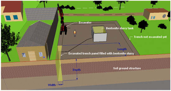
Figure 1.
Trench excavation stage with temporary support from bentonite slurry.
2.1. Shear Strength Reduction Technique
The Shear Strength Reduction Technique (SSR) is a highly popular and efficient numerical method for stability estimation, which aims to evaluate the location of the slip surface and define the factor of safety (FS). The SSR technique, introduced by Zienkiewicz et al. [22], entails progressively reducing the soil strength parameters until failure occurs. Many researchers have applied this technique effectively in slope stability analysis [23,24,25]. Furthermore, the stability analysis of underground openings with complex geology and geometry [26,27], and of large-scale open pit structures [28,29,30,31], has also been effectively carried out using the SSR technique. Here, the SSR technique was applied utilising tools such as RS2 v. 11.0 [32], RS3 v. 4.0 [33], FLAC2D v. 7.0 [34], and FLAC3D v. 7.0 [35] codes to evaluate the stability of excavation trenches with temporary support of bentonite slurry (γs = 10.5 ÷ 12.0 kN/m3).
The numerical models are constructed using a quarter block of soil background structure (Figure 2) with the following dimensions:
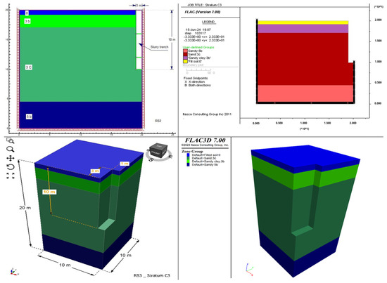
Figure 2.
Geometry of the trench model.
- In 2D (FLAC2D v. 7.0 and RS2 v. 11.0): X × Z = 20 m × 20 m;
- In 3D (FLAC3D v. 7.0 and RS3 v. 4.0): X × Y × Z = 10 m × 10 m (up to 34 m) × 20 m.
The trench model is also represented by a quarter block with the following dimensions:
- In 2D: width × depth = 1 m (or 2 m) × 10 m;
- In (3D): width × length × depth = 1 m (or 2 m) × 6 m × 10 m.
The analysed trench length ranges from 6 m to 54 m.
The trench model was initially built with vertical effective stresses set according to the Mohr–Coulomb material and pore pressures in a static state. Subsequently, the model stresses were reset to prepare for the next step, which involved excavating the trench under bentonite slurry with a density of 10.5–12.0 kN/m3.
The excavation process involved removing elements/nodes of soil layers until the desired excavation depth reached 10 m, while simultaneously applying stress distribution to represent the fluid pressure of the bentonite slurry (Figure 3a,b). It is important to note that the stress distribution of the bentonite slurry was applied along the sides and bottom of the trench to match the unit weight of the bentonite slurry multiplied by the depth of the slurry. This stress distribution of the bentonite slurry was carried out concurrently with the trench excavation, corresponding to each excavation depth. This approach aligns with the site’s construction conditions.
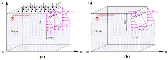
Figure 3.
(a) Bentonite slurry trench with the surcharge load (b) and without the load.
2.2. Bell–Washbourne Method
In Washbourne’s work in 1984 [7], his idealisation involved modifying the shape of the slide wedge from a two-dimensional form (Bell) to a three-dimensional one (Bell–Washbourne) while assuming the angle α between the slide surface and the face of the trench. Stability analysis is similar to the stability of the wedge conducted on the Coulomb wedge in retaining walls. The factor of safety (FS) was calculated as the ratio of the horizontal force due to slurry pressure to the active thrust of the wedge (Figure 4a,b).
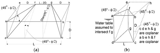
Figure 4.
(a) Oblique view of the simple idealised 3-dimensional wedge with L greater than 2D, (b) oblique view of the simple idealised wedge with L less than 2D. The abed is the slurry soil interface, abcdeh is the Bell [B] 2-dimensional active wedge and abcdfg is the Bell–Washbourne [B-W] 3-dimensional active wedge.
In the original Washbourne study (1984), Equation (1) was employed to calculate the factor of safety.
where Pa = active thrust of the wedge, Ps = slurry support thrust and Pw = thrust on slurry/soil interface of groundwater.
However, this paper presents a different perspective on using equations for factor of safety calculation. Considering the original limit equilibrium condition, the formula for limit equilibrium is
This implies that the factor of safety will be
This formulation fits the classical overloading definition, which defines the factor of safety as the ratio of total resisting forces to total driving forces along a certain slip line.
A comparison reveals that the FS calculated using Equation (1) is significantly greater (which is an overestimation) than that derived from Equation (3). This suggests that Equation (3) would provide a safer outcome and align with the original limit equilibrium mechanism’s initial premise. That is why this paper utilises Equation (3) to compute the factor of safety for the slurry trench.
3. Stability of Bentonite Slurry with Stratum C3
Stratum C3 is located in the suburban area of Hue City, where the construction density ranges from 0% to 30%. It includes mainly residential buildings with small loads of one or two floors and surrounding roads designated for internal traffic vehicles. Therefore, this paper conducted a study for this location with two scenarios: one without any surcharge load and the other with a surcharge load of 10 kPa applied on the ground surface. The geotechnical information of the study area was collected from engineering geological investigation works of laboratories of construction companies operating in Hue city [36,37,38,39,40,41] and from documents by authors such as Nguyen Dinh Tien (2002), Pham Thi Thao (2004) and Le Thi Cat Tuong (2009) [42,43,44]. The average mechanical properties of the soil layers around the C3 main layer are presented in Table 1.

Table 1.
Mechanical properties of the soils.
Discussion of Calculation Results
Firstly, the slurry trench models were built and analysed by FLAC2D v. 7.0, RS2 v. 11.0, and at a trench length of 6 m in 3D (FLAC3D v. 7.0, RS3 v. 4.0). The results demonstrate agreement between FLAC2D v. 7.0 and RS2 v. 11.0, and between FLAC3D v. 7.0 and RS3 v. 4.0, as depicted in Table 2 and Figure 5, Figure 6, Figure 7 and Figure 8. In the case of temporary support with 10.5 kN/m3 bentonite slurry and no surcharge load on the ground surface, the factors of safety (as analysed by RS2 v. 11.0 and FLAC2D v. 7.0) range from 1.26 to 1.32. However, with a surcharge load of 10.0 kPa on the ground surface under the same conditions, the factors of safety decrease and stabilise at values ranging from 1.148 to 1.19.
Table 2.
FS from SSR for the trench with support by bentonite slurry γs = 10.5 ÷ 12.0 kN/m3.
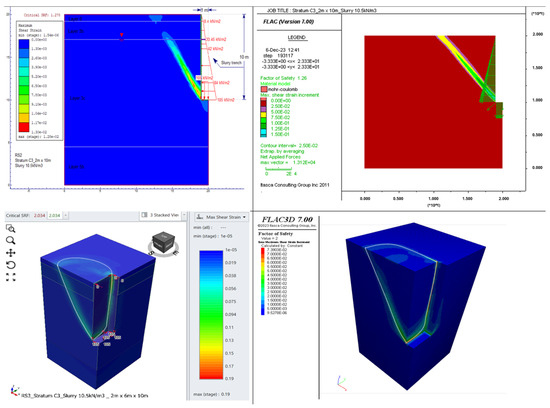
Figure 5.
The failure mode of trenches in FLAC 2D/3D and RS2/3 for the case of γs = 10.5 kN/m3 slurry and no surcharge load on the ground surface.
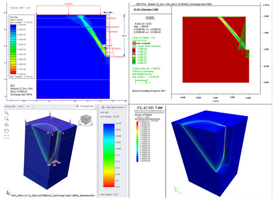
Figure 6.
The failure mode of trenches in FLAC 2D/3D and RS2/3 for the case of γs = 10.5 kN/m3 slurry and surcharge load of 10.0 kPa on the ground surface.
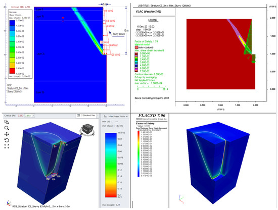
Figure 7.
The failure mode of trenches in FLAC 2D/3D and RS2/3 for the case of γs = 12.0 kN/m3 slurry and no surcharge load on the ground surface.
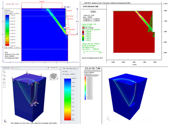
Figure 8.
The failure mode of trenches in FLAC 2D/3D and RS2/3 for the case of γs = 12.0 kN/m3 slurry and surcharge load of 10.0 kPa on the ground surface.
Turning to the case of temporary support with γs = 12 kN/m3 bentonite slurry and no surcharge load on the ground surface, RS2 v. 11.0 and FLAC2D v. 7.0 estimate the factor of safety to range from 1.74 to 1.80. However, with an evenly distributed surcharge load of 10.0 kPa, the factor of safety remains between 1.456 and 1.540.
After analysing the slurry trench with a length of 6 m in 3D, FLAC3D v. 7.0 and RS3 v. 4.0 were also used to conduct stability analysis with an extension of the trench length from 6 m to 54 m. The results show that initially, at a length of 6 m, the factor of safety in 3D is higher than in 2D by an average of 57.8% (Table 1, Figure 5, Figure 6, Figure 7 and Figure 8).
Figure 9 and Figure 10 depict the critical slip surfaces identified, respectively, by FLAC and RS in both 2D and 3D configurations for the case of slurry γs = 10.5 kN/m3 (Figure 9) and 12.0 kN/m3 (Figure 10). Slight differences in the localisation of slip surfaces obtained from both programs are visible.
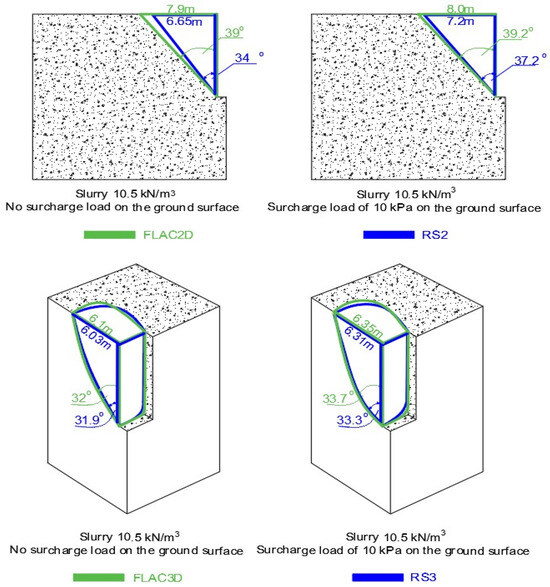
Figure 9.
Critical slip surfaces identified by FLSC and RS for the case of slurry γs = 10.5 kN/m3.
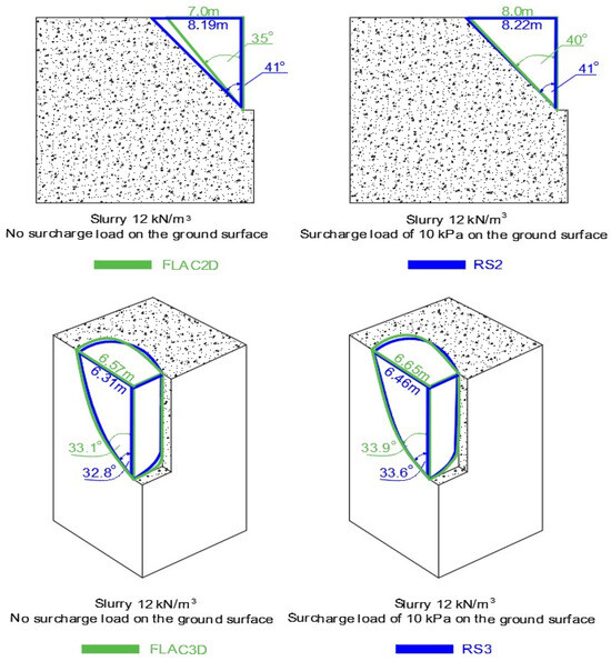
Figure 10.
Critical slip surfaces identified by FLSC and RS for the case of slurry γs = 12.0 kN/m3.
However, as the trench length increases, the factor of safety gradually decreases until, at a length of 54 m, the factors of safety for both 3D and 2D configurations are almost equal.
The limit equilibrium method (LEM) of Bell–Washbourne was also applied to calculate the stability, as mentioned in Section 2.2. After obtaining the stability results using the Bell–Washbourne method, a comparison was made between the Bell–Washbourne method and the numerical one (FLAC, RS). It was observed that the shape of the slip wedge differed between the Bell–Washbourne method and FLAC3D v. 7.0, RS3 v. 4.0, as shown in Figure 11 and Figure 12. The differences are most significant near the narrower edge of the trench. The shape of the slip surface resulting from the Bell–Washbourne method is solely a function of the internal friction angle, and it represents the flat plane close to the narrower end of the trench. The slip surface determined by the SSR method, as a function of the simultaneous reduction of friction and cohesion, is more curved.
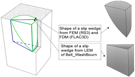
Figure 11.
Shape of a slip wedge for a deep trench (Length < 2Depth).
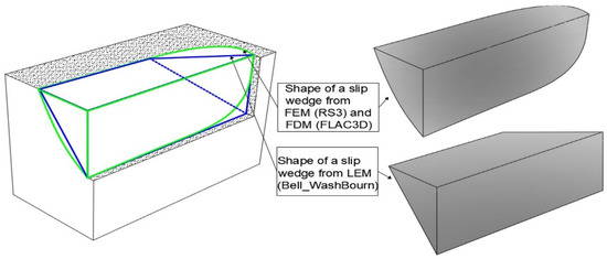
Figure 12.
Shape of a slip wedge for a shallow trench (Length > 2Depth).
The results obtained using FLAC and RS programs were 1.1 to 1.4 times higher than those calculated using the Bell–Washbourne method (Figure 13, Figure 14, Figure 15 and Figure 16).
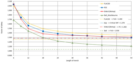
Figure 13.
Variation in FS with trench length using different analysis methods such as FLAC2D, RS2, Bell–Washbourne-2D, RS3, FLAC3D, Slide 3 (Bishop) and Bell–Washbourne-3D for stratum C3 and γs = 10.5 kN/m3.
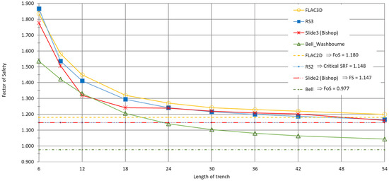
Figure 14.
Variation in FS with trench length using different analysis methods such as FLAC2D, RS2, Bell–Washbourne-2D, RS3, FLAC3D, Slide 3 (Bishop) and Bell–Washbourne-3D for stratum C3 and γs = 10.5 kN/m3 and surcharge load 10 kPa.
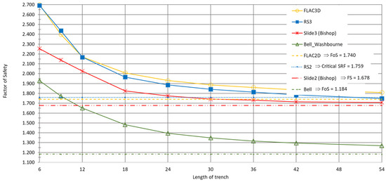
Figure 15.
Variation in FS with trench length using different analysis methods such as FLAC2D, RS2, Bell–Washbourne-2D, RS3, FLAC3D, Slide 3 (Bishop) and Bell–Washbourne-3D for stratum C3 and γs = 12.0 kN/m3.
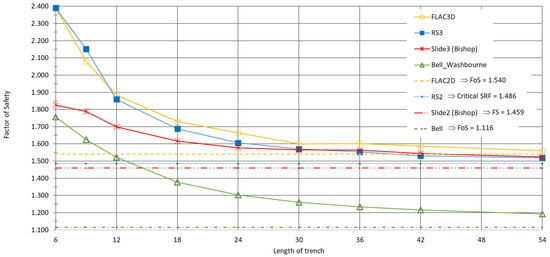
Figure 16.
Variation in FS with trench length using different analysis methods such as FLAC2D, RS2, Bell–Washbourne-2D, RS3, FLAC3D, Slide 3 (Bishop) and Bell–Washbourne-3D for stratum C3 and γs = 12.0 kN/m3 and surcharge load 10 kPa.
The differences in FS values obtained from 3D analyses are greatest for the trench’s smallest dimensions (lengths). In cases without surcharge load, FS values in 2D and 3D are quite high, around 1.3 and higher (Figure 13 and Figure 15). For both cases with surcharge load, FS3D > FS2D. The largest differences between FS2D and FS3D, in the order of 0.1, occur for trench lengths of up to 18 m, decreasing for higher lengths.
4. Conclusions
This article presented comprehensive stability analysis results for slurry trench walls in 2D and 3D configurations for the real conditions of Hue City (Vietnam). These analyses utilised limit equilibrium methods (Bell–Washbourne and Bishop) and numerical simulations based on the Shear Strength Reduction Technique.
The stability and displacement distribution of the slurry trench model were obtained based on predictions from an RS software program (FEM) and an FLAC software program (FDM). A comprehensive series of laboratory tests was also conducted, based on which properties were determined and which individual layer types were identified.
The FS values indicated good agreement between RS2 v. 11.0 and FLAC2D v. 7.0, and between RS3 v. 4.0 and FLAC3D v. 7.0. However, there were significant differences when these methods were compared with LEM results from the Bell–Washbourne and Bishop methods.
Applying the SSR technique in 3D introduced an appropriate FS value for most cases. The 3D model considers each small element in three dimensions, considering complex geological geometries such as thin layers overlapping, arc-shaped slip surfaces, concave surfaces, etc. This approach is sufficiently realistic in analysis.
In 2D, all analyses consider only two dimensions, whereas in 3D all three are considered. This means that, in 2D, the trench is analysed in width × depth, while in 3D it is analysed in width × length × depth. This leads to a difference between 2D and 3D. The result obtained in 2D was equivalent to that in 3D for a certain length dimension, specifically corresponding to a trench length of more than 20–30 m (Figure 13, Figure 14, Figure 15 and Figure 16).
In the LEM of Bell–Washbourne, a simplified method was utilised. This method assumes the sliding mechanism occurs in straight lines rather than in sliding arcs (Figure 11 and Figure 12) for simplicity in stability calculation. This may seem inconsistent with reality since, in reality, the sliding mechanism occurs in the form of a sliding arc.
Although 3D analysis may be an effective method, slurry trench design also requires the consideration of flexibility, balancing safety [23], economy and construction conditions. This entails excavating trench panels, typically with a maximum length of 6 m, corresponding to the length of the wall section. This ensures safe and efficient construction and convenient on-site rotation of materials and machinery equipment. Therefore, a length of 6 m for slurry trench panels was chosen.
The factor of safety of the slurry trench panel length of 6 m, determined using numerical methods in 3D (RS3 v. 4.0 and FLAC3D v. 7.0), exceeded 1.5 (Table 1 and Figure 13, Figure 14, Figure 15 and Figure 16). This factor of safety ensures safety and economic feasibility in the slurry trench design.
The next step should be to verify the calculation and simulation results under in-situ conditions. Applying the presented computational methodology to real cases of trench walls supported with bentonite slurry would be beneficial. Practical verification could also be conducted by measuring displacements on the surface near the excavation, although this is technically challenging.
With the increase in computer speed, 3D numerical analysis appears to be a relatively straightforward and rapid alternative to classical methods for the design and stability analysis of bentonite slurry trenches.
Author Contributions
Conceptualization, T.C.T.L.; methodology, M.C.; software, T.C.T.L.; validation, M.C., A.S. and T.C.T.L.; formal analysis, A.S.; investigation, T.C.T.L.; resources, T.C.T.L.; data curation, T.C.T.L.; writing—original draft preparation, T.C.T.L.; writing—review and editing, M.C.; visualization, T.C.T.L.; supervision, M.C.; project administration, A.S. All authors have read and agreed to the published version of the manuscript.
Funding
This research received no external funding.
Institutional Review Board Statement
Not applicable.
Informed Consent Statement
Not applicable.
Data Availability Statement
The original contributions presented in the study are included in the article, further inquiries can be directed to the corresponding author.
Conflicts of Interest
The authors declare no conflicts of interest.
References
- Budleigh, J.K. Trench Excavation and Support, 1st ed.; Thomas Telford: London, UK, 1989; pp. 26–42. [Google Scholar] [CrossRef]
- McDonald, Y. Trench Support Best Practice Guideline; Christchurch City Council: Christchurch, New Zealand, 2017; pp. 1–11. [Google Scholar]
- Whitlow, R. Basic Soil Mechanics, 2nd ed.; (Translated to Vietnamese, language); John Willey & Sons, Inc.: New York, NY, USA; Vietnamese Education Publisher: Ha Noi, Vietnam, 1999; Volume 2, pp. 21–100. [Google Scholar]
- Kế, N.B. Thiết kế và thi công hố móng sâu, 2nd ed.; Xây Dựng Hà Nội: Hà Nội, Hanoi, Vietnam, 2010; pp. 33–66. (In Vietnamese) [Google Scholar]
- Terzaghi, K.; Peck, R.B.; Mesri, G. Soil Mechanics in Engineering Practice, 3rd ed.; A Wiley-Interscience Publication John Wiley & Sons, Inc.: New York, NY, USA; Chichester, UK; Brisbane, Australia; Toronto, ON, Canada; Singapore, 1996; pp. 241–289. [Google Scholar]
- Piaskowski, A.; Kowalewski, Z. Application of Thixotropic Clay Suspensions for Stability of Vertical Sides of Deep Trenches without Strutting. In Proceedings of the 6th International Conference on Soil Mechanics and Foundation Engineering, Montréal, Canada, 8–15 September 1965; pp. 526–529. [Google Scholar]
- Washbourne, J. The three-dimensional stability analysis of diaphragm wall excavations. Ground Eng. 1984, 17, 24–29. [Google Scholar]
- Tsai, J.S.; Chang, J.C. Three-dimensional stability analysis for slurry-filled trench wall in cohesionless soil. Can. Geotech. J. 1996, 33, 798–808. [Google Scholar] [CrossRef]
- Tamano, T.; Fukui, S.; Suzuki, H.; Ueshita, K. Stability of slurry trench excavation in soft clay. Soils Found. 1996, 36, 101–110. [Google Scholar] [CrossRef] [PubMed]
- Fox, P.J. Analytical Solutions for Stability of Slurry Trench. J. Geotech. Geoenviron. Eng. 2004, 130, 749–758. [Google Scholar] [CrossRef]
- Brząkała, W.; Gorska, K. On safety of slurry-wall trenches. Stud. Geotech. Mech. 2008, 30, 199–206. [Google Scholar]
- Ding, Y.C.; Wang, J.H. Numerical modelling of ground response during diaphragm wall construction. J. Shanghai Jiaotong Univ. Sci. 2008, 13, 385–390. [Google Scholar] [CrossRef]
- Li, Y.-C.; Pan, Q.; Cleall, P.J.; Chen, Y.-M.; Ke, H. Stability Analysis of Slurry Trenches in Similar Layered Soils. J. Geotech. Geoenviron. Eng. 2013, 139, 2104–2109. [Google Scholar] [CrossRef]
- Han, C.; Chen, J.; Wang, J.; Xia, X. 2D and 3D stability analysis of slurry trench in frictional/cohesive soil. Appl. Phys. Eng. 2013, 14, 94–100. [Google Scholar] [CrossRef]
- Zhang, F.; Gao, Y.F.; Leshchinsky, D.; Zhu, D.S.; Lei, G.H. Three-dimensional stability of slurry-supported trenches: End effects. Comput. Geotech. 2016, 74, 174–187. [Google Scholar] [CrossRef]
- Xiao, H.; Sun, Y. Stability analysis of slurry trenches under surcharge in soft soils. In Proceedings of the 7th International Conference on Energy, Environment and Sustainable Development (ICEESD), Shenzhen, China, 30–31 March 2018; Volume 163, pp. 1004–1009. [Google Scholar]
- Li, W.; Zhang, C. Stability Analysis of a Slurry Trench in Cohesive-Frictional Soils. Open Geosci. 2019, 11, 888–900. [Google Scholar] [CrossRef]
- Wang, H.; Huang, M. Upper bound stability analysis of slurry-supported trenches in layered soils. Comput. Geotech. 2020, 122, 103554. [Google Scholar] [CrossRef]
- Wang, H.; Huang, M.; Chian, S.C. Three-dimensional trench stability in non-uniform undrained clay with discretization-based kinematic analysis. Comput. Geotech. 2021, 135, 104166. [Google Scholar] [CrossRef]
- Huang, F.; Wang, Y.; Xu, Y.; Pan, Q.; Wang, D. Three-dimensional Stability Analysis of Slurry Trench Based on Mohr-Coulomb Nonlinear Failure Criterion. KSCE J. Civ. Eng. 2022, 26, 5038–5048. [Google Scholar] [CrossRef]
- Xu, Q.; Xie, J.; Sun, Z.; Lu, L.; Yu, H. Stability Analysis of Trench Wall for Diaphragm Wall in Ultra-Deep Circular Foundation Pit: A Comprehensive Investigation. Appl. Sci. 2023, 13, 12037. [Google Scholar] [CrossRef]
- Zienkiewicz, O.C.; Humpheson, C.; Lewis, R.W. Associated and non-associated visco-plasticity and plasticity in soil mechanics. Geotechnique 1975, 25, 671–689. [Google Scholar] [CrossRef]
- Dawson, E.M.; Roth, W.H.; Drescher, A. Slope stability analysis by strength reduction. Geotechnique 1999, 49, 835–840. [Google Scholar] [CrossRef]
- Cała, M.; Flisiak, J. Complex geology slope stability analysis by shear strength reduction. In FLAC and Numerical Modeling in Geomechanics 2003, Proceedings of the 3rd International FLAC Symposium, Sudbury, ON, Canada, 22–24 October 2003; Andrieux, P., Brummer, R., Detournay, C., Hart, R., Eds.; CRC Press: Boca Raton, FL, USA, 2003. [Google Scholar]
- Cała, M. Convex and concave slope stability analyses with numerical methods. Arch. Min. Sci. 2007, 52, 75–89. [Google Scholar]
- Cała, M.; Stopkowicz, A.; Cyran, K.; Kowalski, M.; Blajer, M.; d’Obyrn, K. Stability analysis of underground mining openings with complex geometry. Stud. Geotech. Mech. 2016, 38, 25–32. [Google Scholar] [CrossRef][Green Version]
- Cała, M.; Cyran, K.; Kowalski, M.; Wilkosz, P. Influence of the anhydrite interbeds on a stability of the storage caverns in the Mechelinki salt deposit (Northern Poland). Arch. Min. Sci. 2018, 63, 1007–1025. [Google Scholar]
- Adamczyk, J.; Cała, M.; Flisiak, J.; Kolano, M.; Kowalski, M. Slope stability analysis of waste dump in Sandstone Open Pit Osielec. Stud. Geotech. Mech. 2013, 35, 3–17. [Google Scholar] [CrossRef]
- Cała, M.; Kowalski, M.; Stopkowicz, A. The three-dimensional (3D) numerical stability analysis of Hyttemalmen open-pit. Arch. Min. Sci. 2014, 59, 609–620. [Google Scholar] [CrossRef]
- Jakóbczyk, J.; Cała, M.; Stopkowicza, A. What were the reasons for the rapid landslide occurrence in “Piaseczno” open pit?—Analysis of the landslide process. Stud. Geotech. Mech. 2015, 37, 25–35. [Google Scholar] [CrossRef]
- Cała, M.; Cyran, K.; Jakóbczyk, J.; Kowalski, M. The challenges of open-pit mining in the vicinity of the salt dome (Bełchatów Lignite Deposit, Poland). Energies 2020, 13, 1913. [Google Scholar] [CrossRef]
- Rocscience, RS2 Version 11.012 2D Geotechnical Finite Element Analysis Rocscience, Tutorials. 2012. Available online: https://www.rocscience.com/software/rs2 (accessed on 14 February 2023).
- Rocscience, RS3 Tutorials. Available online: https://www.rocscience.com/help/rs3/tutorials (accessed on 14 February 2023).
- Itasca Consulting Group. FLAC2D-Fast Lagrangian Analysis of Continua, Ver. 7.0 User’s Manual; Itasca Consulting Group: Minneapolis, MN, USA, 2011. [Google Scholar]
- Itasca Consulting Group. FLAC Theory and Background—Itasca Software Documentation. Available online: https://docs.itascacg.com/itasca900/flac3d/docproject/source/theory/theory.html?node2317 (accessed on 11 October 2023).
- Công ty cổ phần tư vấn thiết kế tổng hợp. Báo cáo khảo sát địa chất công trình: Khách sạn Monial—Thành Phố Huế; Công ty cổ phần tư vấn thiết kế tổng hợp: Ha Noi, Vietnam, 2005. (In Vietnamese) [Google Scholar]
- Công ty cổ phần tư vấn thiết kế tổng hợp. Báo cáo khảo sát địa chất công trình: Viện quy hoạch xây dựng Thừa Thiên Huế; Công ty cổ phần tư vấn thiết kế tổng hợp: Ha Noi, Vietnam, 2007. (In Vietnamese) [Google Scholar]
- Công ty Tư vấn xây dựng số 1 Thừa Thiên Huế. Thuyết minh địa chất: Công ty Cổ phần Vật liệu Xây dựng Huế; Công ty Tư vấn xây dựng số 1 Thừa Thiên Huế: Ha Noi, Vietnam, 2010. (In Vietnamese) [Google Scholar]
- Công ty Tư vấn xây dựng số 1 Thừa Thiên Huế. Thuyết minh địa chất: Bệnh viện Ngoại khoa Quốc tế Huế; Công ty Tư vấn xây dựng số 1 Thừa Thiên Huế: Ha Noi, Vietnam, 2011. (In Vietnamese) [Google Scholar]
- Công ty Tư vấn xây dựng số 1 Thừa Thiên Huế. Thuyết minh địa chất: Trụ sở Công An Phường Phú Hiệp; Công ty Tư vấn xây dựng số 1 Thừa Thiên Huế: Ha Noi, Vietnam, 2014. (In Vietnamese) [Google Scholar]
- Công ty Tư vấn xây dựng số 1 Thừa Thiên Huế. Báo cáo khảo sát địa chất công trình: VỸ DẠ Boutique Resort; Công ty Tư vấn xây dựng số 1 Thừa Thiên Huế: Ha Noi, Vietnam, 2016. (In Vietnamese) [Google Scholar]
- Tường, L.T.C. Nghiên cứu dự báo những vấn đề địa chất công trình đối với hố móng sâu trên các kiểu cấu trúc nền khu vực thành phố Huế và đề xuất giải pháp ổn định hố móng. Master’s Thesis, Hue Science University, Hue, Vietnam, 2009. [Google Scholar]
- Thảo, P.T. Nghiên cứu các kiểu cấu trúc nền đất yếu khu vực thành phố Huế và đề xuất giải pháp kỹ thuật cải tạo hợp lý. Master’s Thesis, Hue Science University, Hue, Vietnam, 2004. [Google Scholar]
- Tiến, N.Đ.; Bảo, N.Đ. Đặc điểm địa chất khu vực thành phố Huế, Thừa Thiên Huế. 2002. Available online: https://csdlkhoahoc.hueuni.edu.vn/index.php/topic/index/user/95/page/2 (accessed on 1 June 2024).


Disclaimer/Publisher’s Note: The statements, opinions and data contained in all publications are solely those of the individual author(s) and contributor(s) and not of MDPI and/or the editor(s). MDPI and/or the editor(s) disclaim responsibility for any injury to people or property resulting from any ideas, methods, instructions or products referred to in the content. |
© 2024 by the authors. Licensee MDPI, Basel, Switzerland. This article is an open access article distributed under the terms and conditions of the Creative Commons Attribution (CC BY) license (https://creativecommons.org/licenses/by/4.0/).