Abstract
This article proposes an autonomous greenhouse system which has a sunlight Reflector Board (RB). In general, a greenhouse, which grows leafy vegetables, utilizes artificial light, such as LED light, as a supplementary source of light. However, artificial light cannot be used as the main source of light for photosynthesis for various kinds of plants. Our article utilizes natural sunlight, instead of artificial light, for growing plants inside a greenhouse. We develop an autonomous system to control the amount of sunlight inside the greenhouse by controlling the angle of the RB, which is located in front of the greenhouse. Since the proposed greenhouse uses natural sunlight, one can grow various kinds of plants which cannot grow under artificial light. Suppose that we accumulate the RB angle data for one year. Since solar motion repeats every year, we can control the RB according to this accumulated angle data. In this way, we can reduce unnecessary RB controls, after running the system for more than a year. As far as we know, the proposed greenhouse system based on autonomous RB controls is novel, since we control RBs for providing optimal sunlight for plants inside the greenhouse. We perform experiments to demonstrate the performance of the proposed greenhouse system.
1. Introduction
This research proposes an autonomous greenhouse system which has a sunlight reflector board (RB). Here, a greenhouse refers to an autonomous farm that can manage the growing environment of plants inside the greenhouse.
In general, a greenhouse, which grows leafy vegetables, utilizes artificial light, such as LED light, as a supplementary source of light. However, artificial light cannot be used as the main source of light for photosynthesis for various kinds of plants.
In our article, we utilize natural sunlight, instead of artificial light, for growing plants inside a greenhouse. Since the proposed greenhouse uses natural sunlight, one can grow various kinds of plants which cannot grow under artificial light. We develop an autonomous system to control the amount of sunlight inside the greenhouse by controlling the angle of the RB, which is located in front of the greenhouse. We periodically control the RB of sunlight, so that the optimal sunlight amount, which is set by the operator, can be provided for the plants inside the farm. We acknowledge that artificial light can be used as a supplementary source of light in cloudy days.
There are many papers on smart solar tracking systems. Refs. [1,2,3] addressed smart solar tracking systems, which can increase the output power of solar panels. The solar tracking system in [2] utilized the difference between the reading of the light sensors on the top and bottom of the solar panel. When the difference is equal to zero, the position of sunlight is precisely in the middle of the solar panel. The goal of a solar tracking system is to arrange the solar panel, so that the panel is perpendicular to the sunlight direction. In this way, one can maximize the output power of solar panels. Our research is distinct from solar tracking systems [1,2,3], since we control the RB of sunlight, so that the optimal sunlight amount, which is set by the operator, can be provided for the plants inside the farm.
There are many papers on monitoring smart farm systems [4,5,6,7,8]. Ref. [9] addressed automated agricultural processes (seeding, ploughing, irrigation, planting, fertilizing, weeding, or harvesting) using a programmable logic controller and zigbee network. Ref. [10] built a greenhouse system using low-power bluetooth and low-power wide area network communication modules including a wired communication network. Ref. [11] studied weather station and mobile data logging type monitoring. Ref. [5] utilized the Internet of Things, wireless networks, and message queuing telemetry tracking to monitor the agricultural environment in real time. Ref. [6] addressed a smart farm system including the monitoring of soil moisture and atmospheric sensors (temperature and relative humidity). Ref. [7] proposed a strategy for smart irrigation to optimize water consumption and to provide a remote control and monitoring of the irrigation system. Ref. [8] proposed to implement a wireless sensor network connected to a central node, which is connected to a central monitoring station. Ref. [12] proposed a trust model for monitoring humidity and moisture in agricultural environments. Moisture content (MC) detection plays a vital role in the monitoring and management of living trees. Targeting the drawbacks of high energy consumption, low practicability, and poor sustainability in the current field of living tree MC detection, Ref. [13] addressed an ultra-high-frequency radio frequency identification (UHF RFID) sensor system based on a deep learning model, with the main goals of non-destructive testing and high-efficiency recognition. Ref. [14] addressed the application of Internet-of-Things (IoT) technology in agricultural soil measurements, which consists of multiple sensors (temperature and moisture), a micro-processor, a microcomputer, a cloud platform, and a mobile phone application. The wireless sensors can collect and transmit soil information in real time, while the mobile phone app uses the cloud platform as a monitoring center. Ref. [14] proved that a mobile phone app can be effectively used for the real-time monitoring of soil quality and conditions in wireless multi-sensing based on the IoT. As far as we know, most smart farms have been developed mainly for environmental monitoring or environment controls of smart farms.
To the best of our knowledge, a smart farm in the literature utilized artificial light, such as LED light, for shedding light onto plants. Ref. [15] studied the effects of artificial LED light on metabolism, growth, and photosynthesis in leafy vegetables and some selected plants. However, artificial light cannot be used as the main source of light for photosynthesis for various kinds of plants. Our strategy is controlling the RB periodically, so that the appropriate amount of natural sunlight intensity can be provided for the plants inside the farm. Since the proposed greenhouse uses the natural sunlight, one can grow various kinds of plants which cannot grow under artificial light. We argue that the proposed RB control strategy can be useful in regions with sufficient sunlight intensity, such as Middle East countries.
Suppose that we accumulate the RB angle data for one year. Since solar motion repeats every year, we can control the RB according to this accumulated angle data. In this way, we can reduce unnecessary RB adjustments, after running the system for more than a year.
As far as we know, the proposed greenhouse system based on autonomous RB controls is novel, since we control RBs for providing optimal sunlight for plants inside the greenhouse. Simple controls are computationally efficient, robust, easy to implement, and easy to debug. Thus, we address simple RB controls, such that optimal sunlight can be provided for plants inside the greenhouse. We perform experiments to demonstrate the performance of the proposed RB controls.
2. The RB Controls
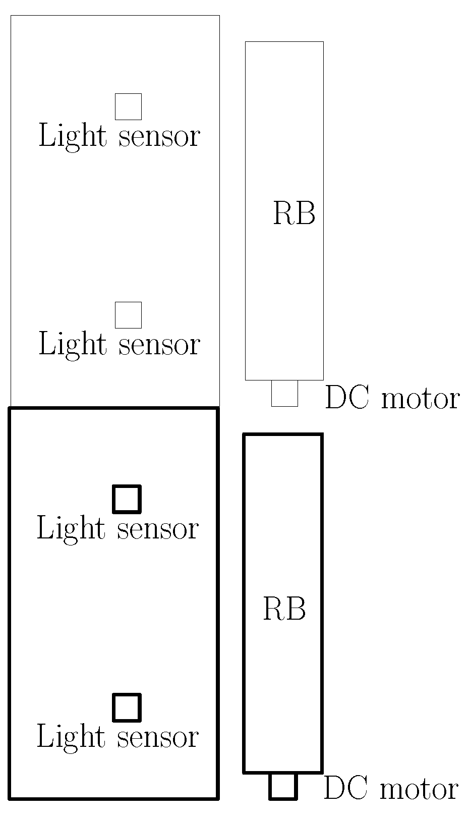
We address a modular greenhouse system which can be extended to a long greenhouse. For instance, Figure 1 plots the top view of a long greenhouse. In this long greenhouse, there are two modular greenhouses, and a bold figure indicates one modular greenhouse. As we consider a long greenhouse, we can connect modular greenhouses side by side. In Figure 1, two RBs are installed on one side of a long greenhouse.

Figure 1.
An illustration of a long greenhouse structure (top view). Two RBs are installed on one side of a long greenhouse.
Suppose that there are several light sensors inside the farm greenhouse. These light sensors are installed to measure light intensity inside the farm in real time. Let indicate the mean of all intensity measurements inside the greenhouse. The RB in our research moves according to the mean intensity .
The RB is installed, as depicted in Figure 1. By controlling the motor attached to the RB, we control the light intensity inside the farm. The greenhouse system can control the RB angle precisely, since encoders are installed on the motor.
Figure 2 depicts the proposed RB control system. The sunlight is depicted as an arrow. The RB controls the light shed onto the plants inside the farm. The RB is depicted with a red line segment. Figure 2 shows that the light reflects many times inside the farm, because of reflective films installed inside the farm. The sunlight is reflected by the RB on the right side of the figure. Then, we control the RB angle, in order to provide the optimal amount of sunlight which is set by the operator.
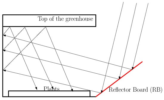
Figure 2.
An illustration of the proposed RB control system. The sunlight is depicted as an arrow. The RB controls the light onto the plants inside the farm. The light reflects inside the farm, since reflective films are installed inside the farm. The RB is depicted with a red line segment.
2.1. Control the RB for Providing the Designated Sunlight Set by the Operator
Let denote the designated light intensity set by the operator. is set depending on the plants inside the farm.
This subsection addresses autonomous RB controls, so that the set sunlight intensity can be provided for the plants inside the farm. We control the RB periodically, so that the designated sunlight intensity can be provided for plants inside the farm. In order to obtain the RB angle at which the desired light intensity is obtained, we utilize the light control algorithm in Algorithm 1.
In Algorithm 1, denotes the current RB angle. As we initialize Algorithm 1, we initialize . At every minutes, the RB changes its angle with step size . Let denote the average of the mean light intensity , while the RB stays still for minutes. Here, the RB stays still for minutes, in order to obtain a stabilized intensity measurement.
| Algorithm 1 RB controls for providing the designated sunlight intensity set by the operator |
Measure the light intensity , while staying still at the current RB angle for minutes; ifthen ; end if ifthen ; end if if we find a RB angle, such that under Algorithm 1 or then Maintain the RB angle for S minutes until moving the RB under Algorithm 1; IterationCount = 0; else Re-run Algorithm 1; IterationCount = IterationCount + 1; end if |
Suppose that Algorithm 1 ends and that the difference between the measured light intensity and is smaller than a certain threshold, say . As time goes on, the Sun light direction changes, since the earth rotates continuously. Thus, we maintain the set RB angle for S minutes, until moving the RB again using Algorithm 1. In our experiments, we set S as 10 min. In practice, we can set a large S, such as one hour.
In practice, running Algorithm 1 may not provide the light intensity which is sufficiently close to the desired light intensity. This case may happen due to various environmental conditions, such as temporary blocking of Sun light due to cloud.
Suppose that Algorithm 1 ends and that the difference between the measured light intensity and is larger than . In this case, we re-run Algorithm 1, in order to find the optimal RB angle again. This process iterates until the difference between the measured light intensity and is smaller than . In Algorithm 1, indicates how many times this algorithm re-runs iteratively. As we re-run Algorithm 1, increases by one.
In order to avoid the case where Algorithm 1 keeps iterating infinitely, iteration of Algorithm 1 stops after Algorithm 1 runs more than times. Here, Q is a constant set by the farm operator. In experiments, we set . In this way, we can avoid infinite movements of the RB.
2.2. Control the Light RB according to Accumulated Angle Data
While we operate the greenhouse system, we can upload the RB angle and in the Secure Digital (SD) card. When data are uploaded, the upload time information is recorded in the SD card. The DS1307 module is used to compute the upload time information.
Suppose that we accumulate the RB angle data for one year. Since solar motion repeats every year, we can control the light RB according to this accumulated angle data. In this way, we can reduce unnecessary RB controls after running the system for more than a year.
3. Experiments of the RB Control in the Proposed Greenhouse System
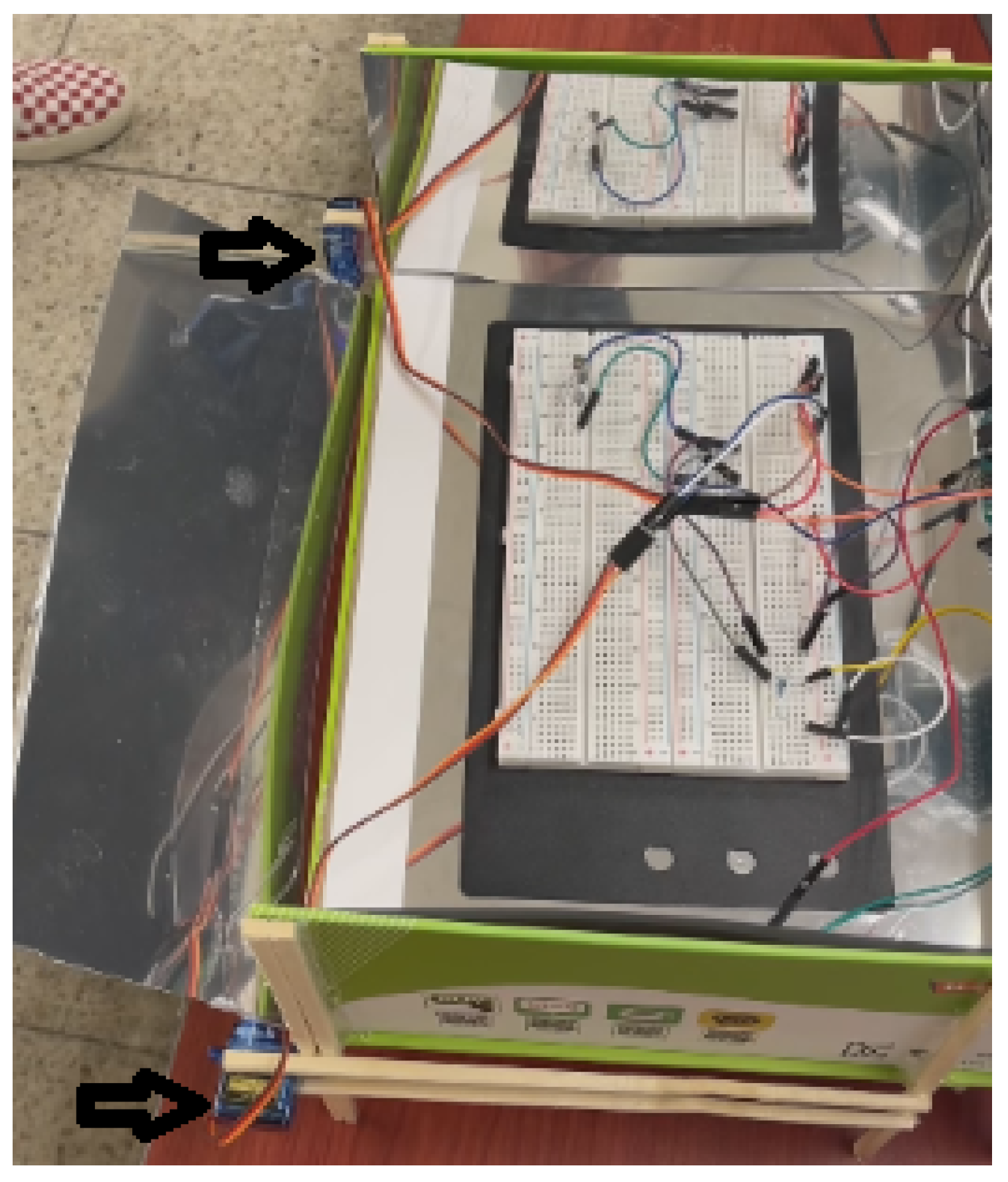
As far as we know, the proposed greenhouse system based on autonomous RB controls is novel, since we control RBs for providing optimal sunlight for plants inside the greenhouse. We address experiments of the RB control in the proposed greenhouse system. Using a small box, we made a small greenhouse to test our RB control algorithms, as plotted in Figure 3. We install this greenhouse on outdoor open environments, so that sufficient sunlight can be provided onto the greenhouse. The experiments are performed for three hours (11:00–14:00). Figure 3 plots the RB installed in front of the greenhouse. Figure 3 shows a breadboard inside the box. On the breadboard, we install two light sensors.
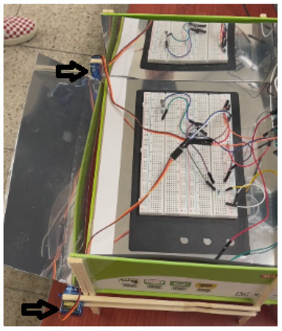
Figure 3.
Using a small box, we made a small greenhouse to test our algorithms. This figure shows the RB installed in front of the greenhouse. Arduino Nano is utilized to control the RB, and the RB is controlled using two encoder motors at both sides of the RB. We utilize encoders to measure the RB angle in real time. Inside the greenhouse, we attached tinfoils to enable sunlight reflection. Two encoder motors are marked with two arrows, respectively. This figure shows a breadboard inside the box. On the breadboard, we install two light sensors.
We explain the experiment setup of our research. Arduino is an open-source micro-controller, which is widely utilized for implementing IoT devices [16]. We utilized an Arduino Nano which is a miniaturized model with an ATmega328 processor (Microchip Technology Incorporated, Chandler, AZ, USA).
Arduino Nano (Arduino, Somerville, MA, USA) is utilized to control the RB, and the RB is controlled using two encoder motors at both sides of the RB. We utilize encoder motors to control the RB, while measuring the RB angle in real time. Inside the small greenhouse, we attached tinfoils to enable sunlight reflection. In addition, two light sensors are installed on the breadboard inside the greenhouse. The measurements of the light sensors, RB angles, and the associated time information are stored in the SD card. By controlling the encoder motor attached to the RB, we control the light intensity inside the farm. We can control the RB angle precisely, since we install encoder motors. In Figure 3, two encoder motors are marked with two arrows, respectively.
Our control settings are as follows. In Algorithm 1, we utilize min, since the light sensors can obtain stable light measurements within 1 min. In experiments, we utilize the angle step size as degrees. In addition, is set as 25 Lux.
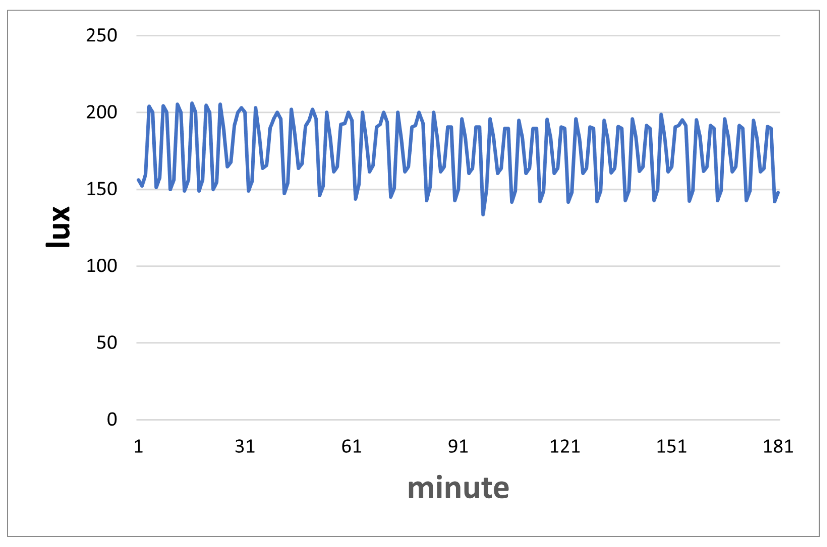
Experiments are carried out to demonstrate the performance of the proposed RB controls in Section 2.1. The experiments are performed for three hours. Inside the greenhouse, we measure the light intensity at every one minute, i.e., min.
Recall that denotes the light intensity set by the operator. We set lux in our RB experiments.
Figure 4 plots the experimental results proving the effectiveness of proposed RB controls in Section 2.1. Algorithm 1 is utilized to control the RB, for providing the optimal amount of sunlight which is set by the operator. The mean light intensity remains close to (175 lux) under the light control system (Algorithm 1). This proves the effectiveness of Algorithm 1 in providing the optimal sunlight for plants.
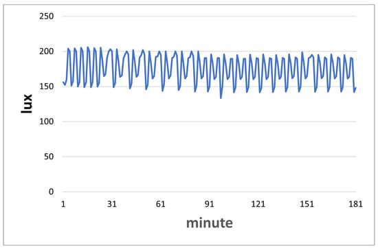
Figure 4.
The experimental results showing the effect of controls in Section 2.1. The mean light intensity remains close to (175 lux) under the light control system (Algorithm 1).
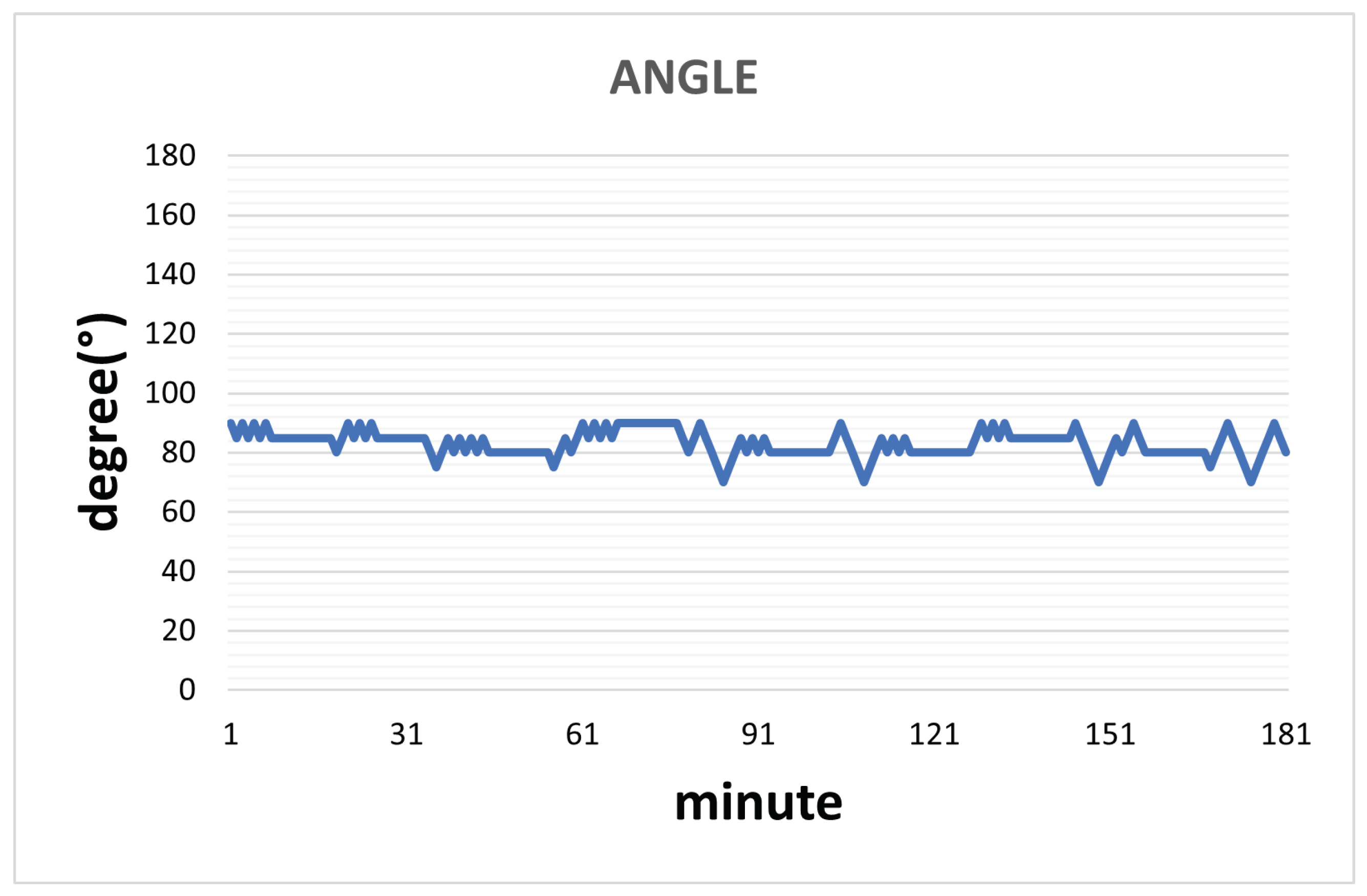
Figure 5 shows the change of RB angle (in degrees) associated with the experiments in Figure 4. In Figure 5, Algorithm 1 is utilized to control the RB for providing the optimum amount of sunlight. Once we set a RB angle using Algorithm 1, we maintain the angle for min until moving the RB again.
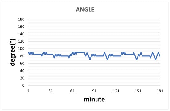
Figure 5.
The change in RB angle (in degrees) associated with the experiments in Figure 4. Algorithm 1 is utilized to control the RB for providing the optimum amount of sunlight. Once we set an RB angle using Algorithm 1, we maintain the angle for min until moving the RB again.
4. Discussion
IoT-enabled automated greenhouse systems can increase the productivity of plants grown in the greenhouse by monitoring and controlling various parameters, such as humidity, mist, CO2 level, UV light intensity, water nutrients solution level, temperature, and amount of pesticides, through sensors for further efficient detection and diagnosis [17]. The proposed greenhouse can be extended to an integrated system, such that a greenhouse operator can monitor various environmental parameters, such as temperature, humidity, and carbon dioxide, inside the greenhouse.
In our integrated system, an operator can set various environmental parameters, such as temperature, humidity, and carbon dioxide, inside the greenhouse. Once the environmental parameters are set, the greenhouse system operates to achieve the set parameters autonomously. The system controls carbon dioxide (CO2), temperature, humidity, and sunlight intensity inside the greenhouse autonomously.
CO2 sensors, temperature sensors, and humidity sensors can be installed inside the greenhouse. In addition, following facilities can be installed inside the greenhouse: CO2 generators, air conditioners, heaters, and dehumidifiers. CO2 generators are used to generate CO2 inside the greenhouse. Air conditioners and heaters are used to control the temperature inside the greenhouse. In addition, dehumidifiers are installed to decrease the humidity inside the greenhouse.
For instance, assume that the temperature setting by an operator is in the interval . If the current temperature is above , then the air conditioner is turned on for decreasing the temperature. If the current temperature is below , then the heater is turned on for increasing the temperature. If the current temperature is within the interval , then both the air conditioner and the heater are turned off. In this way, the greenhouse system can control CO2, temperature, humidity inside the house automatically, so that the operator does not have to turn on/off each facility manually.
Arduino is an open-source micro-controller, which is widely utilized for implementing IoT devices [16]. Depending on the sensor measurements, the Arduino turns on/off the following facilities inside the greenhouse: CO2 generators, air conditioners, heaters, and dehumidifiers. The sensor measurments and the associated time information can be uploaded in the SD card. Here, the DS1307 module (Dallas Semiconductor, Dallas, TX, USA) is used to compute the upload time information.
If necessary, the sensor measurements and the operation state can be transmitted to a remote operator using Wifi communications or Lora module (Semtech Corporation, Irvine, CA, USA). Ref. [14] proved that mobile phone app can be effectively used for the real-time monitoring of soil quality and conditions in wireless multi-sensing based on the IoT. Similarly to [14], sensor measurements and the operation state can be displayed and controlled using mobile phone app of the operator.
5. Conclusions
This study addresses an autonomous RB control system, which controls the amount of sunlight inside the farm. Since the proposed greenhouse uses the natural sunlight, one can grow various kinds of plants which cannot grow under artificial light. Once we set an RB angle using Algorithm 1, we maintain the angle for S minutes until moving the RB again. We control the RB of sunlight, so that the optimal amount (which is set by the operator) of sunlight can be provided for the plants inside the farm. To the best of our knowledge, the proposed greenhouse system based on autonomous RB controls is novel, since we control RBs for providing optimal sunlight for plants inside the greenhouse. Experiments are utilized to demonstrate the performance of the proposed greenhouse system.
In the future, we will carry out experiments using a large-scale greenhouse, such that an operator can monitor and set various parameters, such as temperature, humidity, sunlight intensity, and CO2 inside the greenhouse. Once the parameters are set by the operator, the greenhouse system works to achieve the set parameters autonomously, as presented in Section 4. We will build a modular greenhouse system which can be extended to a long greenhouse, as plotted in Figure 1.
In this paper, an RB is located in front of the greenhouse. However, the place of RBs can change if necessary. For instance, considering a Fenluo type greenhouse, RBs can be installed on the house’s roof. We can apply Algorithm 1 for controlling the RBs. As we control the RBs, direct or reflected sunlight can be provided for plants inside the greenhouse.
The proposed greenhouse can be powered by solar cells on the greenhouse. On top of the greenhouse, solar cells can be installed to obtain sufficient power for operating facilities in the greenhouse. We argue that the proposed RB control strategy can be useful in regions with sufficient sunlight intensity, such as Middle East countries.
Funding
This work was supported by the National Research Foundation of Korea (NRF) grant funded by the Korea government (MSIT) (Grant Number: 2022R1A2C1091682).
Institutional Review Board Statement
Not applicable.
Informed Consent Statement
Not applicable.
Data Availability Statement
Data is contained within the article.
Conflicts of Interest
The author declare no conflicts of interest.
References
- Hafez, A.; Yousef, A.; Soliman, A.; Ismail, I. A comprehensive review for solar tracking systems design in Photovoltaic cell, module, panel, array, and systems applications. In Proceedings of the 2018 IEEE 7th World Conference on Photovoltaic Energy Conversion (WCPEC) (A Joint Conference of 45th IEEE PVSC, 28th PVSEC & 34th EU PVSEC), Waikoloa, HI, USA, 10–15 June 2018; pp. 1188–1193. [Google Scholar]
- Atmoko, R.A.; Sarena, S.T.; Adhitya, R.Y.; Hartono, D.; Yang, D. Reflector based smart solar tracker (RBSST) as a solution of global climate change and its economic analysis for 900VA customer. AIP Conf. Proc. 2020, 2278, 020013. [Google Scholar]
- Tharamuttam, J.K.; Ng, A.K. Design and Development of an Automatic Solar Tracker. Energy Procedia 2017, 143, 629–634. [Google Scholar] [CrossRef]
- Serikul, P.; Nakpong, N.; Nakjuatong, N. Smart Farm Monitoring via the Blynk IoT Platform: Case Study: Humidity Monitoring and Data Recording. In Proceedings of the 2018 16th International Conference on ICT and Knowledge Engineering (ICT&KE), Bangkok, Thailand, 21–23 November 2018; pp. 1–6. [Google Scholar]
- Mukherji, S.V.; Sinha, R.; Basak, S.; Kar, S.P. Smart Agriculture using Internet of Things and MQTT Protocol. In Proceedings of the 2019 International Conference on Machine Learning, Big Data, Cloud and Parallel Computing (COMITCon), Faridabad, India, 14–16 February 2019; pp. 14–16. [Google Scholar]
- Coelho, A.D.; Dias, B.G.; de Oliveira Assis, W.; de Almeida Martins, F.; Pires, R.C. Monitoring of Soil Moisture and Atmospheric Sensors with Internet of Things (IoT) Applied in Precision Agriculture. In Proceedings of the 2020 XIV Technologies Applied to Electronics Teaching Conference (TAEE), Porto, Portugal, 8–10 July 2020; pp. 1–8. [Google Scholar]
- Khelifa, B.; Amel, D.; Amel, B.; Mohamed, C.; Tarek, B. Smart irrigation using internet of things. In Proceedings of the 2015 Fourth International Conference on Future Generation Communication Technology (FGCT), Luton, UK, 29–31 July 2015; pp. 1–6. [Google Scholar]
- Satyanarayana, G.V.; Mazaruddin, S. Wireless Sensor Based Remote Monitoring System for Agriculture Using ZigBee and GPS. In Conference on Advances in Communication and Control Systems (CAC2S 2013); Atlantis Press: Amsterdam, The Netherlands, 2013; pp. 110–114. [Google Scholar]
- A. Dhivya, J.I.; Chakrapani, K. Automated Agricultural Process Using PLC and ZigBee. J. Artif. Intell. 2012, 5, 170–177. [Google Scholar] [CrossRef]
- Yoon, C.; Huh, M.; Kang, S.G.; Park, J.; Lee, C. Implement smart farm with IoT technology. In Proceedings of the 2018 20th International Conference on Advanced Communication Technology (ICACT), Chuncheon, Republic of Korea, 11–14 February 2018; pp. 749–752. [Google Scholar]
- Lohchab, V.; Kumar, M.; Suryan, G.; Gautam, V.; Das, R.K. A Review of IoT based Smart Farm Monitoring. In Proceedings of the 2018 Second International Conference on Inventive Communication and Computational Technologies (ICICCT), Coimbatore, India, 20–21 April 2018; pp. 1620–1625. [Google Scholar]
- Prodanović, R.; Sarang, S.; Rančić, D.; Vulić, I.; Stojanović, G.M.; Stankovski, S.; Ostojić, G.; Baranovski, I.; Maksović, D. Trustworthy Wireless Sensor Networks for Monitoring Humidity and Moisture Environments. Sensors 2021, 21, 3636. [Google Scholar] [CrossRef] [PubMed]
- Wu, Y.; Zhang, C.; Liu, W. Living Tree Moisture Content Detection Method Based on Intelligent UHF RFID Sensors and OS-PELM. Sensors 2022, 22, 6287. [Google Scholar] [CrossRef] [PubMed]
- Wu, Y.; Yang, Z.; Liu, Y. Internet-of-Things-Based Multiple-Sensor Monitoring System for Soil Information Diagnosis Using a Smartphone. Micromachines 2023, 14, 1395. [Google Scholar] [CrossRef] [PubMed]
- Olle, M.; Viršile, A. The effects of light-emitting diode lighting on greenhouse plant growth and quality. Agric. Food Sci. 2013, 22, 223–234. [Google Scholar] [CrossRef]
- Arduino. 2022. Available online: https://www.arduino.cc/ (accessed on 14 June 2024).
- Dhanaraju, M.; Chenniappan, P.; Ramalingam, K.; Pazhanivelan, S.; Kaliaperumal, R. Smart Farming: Internet of Things (IoT)-Based Sustainable Agriculture. Agriculture 2022, 12, 1745. [Google Scholar] [CrossRef]

Disclaimer/Publisher’s Note: The statements, opinions and data contained in all publications are solely those of the individual author(s) and contributor(s) and not of MDPI and/or the editor(s). MDPI and/or the editor(s) disclaim responsibility for any injury to people or property resulting from any ideas, methods, instructions or products referred to in the content. |
© 2024 by the author. Licensee MDPI, Basel, Switzerland. This article is an open access article distributed under the terms and conditions of the Creative Commons Attribution (CC BY) license (https://creativecommons.org/licenses/by/4.0/).