Article

Solving a Multi-Objective Optimization Problem of a Two-Stage Helical Gearbox with Second-Stage Double Gear Sets Using the MAIRCA Method

1
Faculty of Mechanical Engineering, Viet Tri University of Industry, 09 Tien Son Street, Viet Tri City 35100, Vietnam
2
Faculty of Mechanical Engineering, Vinh Long University of Technology Education, 73 Nguyen Hue Street, Ward 2, Vinh Long City 85110, Vietnam
3
Electronics and Electrical Department, East Asia University of Technology, Trinh Van Bo Street, Hanoi City 12000, Vietnam
4
School of Engineering and Technology, Duy Tan University, 03 Quang Trung Street, Hai Chau Ward, Da Nang City 550000, Vietnam
5
Faculty of Mechanical Engineering, Thai Nguyen University of Technology, 3/2 Street, Tich Luong Ward, Thai Nguyen City 251750, Vietnam
*
Author to whom correspondence should be addressed.
Appl. Sci. 2024, 14(12), 5274; https://doi.org/10.3390/app14125274
Submission received: 28 May 2024 / Revised: 16 June 2024 / Accepted: 17 June 2024 / Published: 18 June 2024

Abstract

:
This paper provides a novel application of the multi-criteria decision-making (MCDM) method to the multi-objective optimization problem (MOOP) of creating a two-stage helical gearbox (TSHG) with second-stage double gear sets (SDGSs). The aim of the study is to determine the optimum major design components for enhancing the gearbox efficiency while reducing the gearbox volume. In this work, three primary design parameters are chosen to accomplish this: the gear ratio of the first stage and the coefficients of the wheel face width (CWFW) of the first and second stages. Additionally, the study is conducted with two distinct objectives in mind: the lowest gearbox volume and the maximum gearbox efficiency. Moreover, phase 1 and phase 2, respectively, are the two stages of the MOOP. Phase 2 handles the MOOP to identify the ideal primary design factors as well as the single-objective optimization problem to minimize the difference between the variable levels. Additionally, the Multi-Attributive Ideal–Real Comparative Analysis (MAIRCA) approach is selected to deal with the MOOP. The results of the study are utilized to determine the ideal values for three crucial design parameters in order to create a TSHG with SDGSs.

1. Introduction

A gearbox is a crucial part of a mechanical drive system. It is employed to improve the torque and decrease the speed from the input to the output of the gearbox. In reality, there are a wide variety of forms of gearboxes: worm, planetary, bevel, and cylindrical gearboxes (with spur or helical gears). Because they operate more smoothly and silently than spur-gear gearboxes, helical gearboxes are highly common and exceed other types of gearboxes in terms of efficiency [1]. This is the rationale behind the efforts of numerous academics to optimize the helical gearbox.
Up to now, there has been quite a lot of research on optimizing a helical gearbox. Research on helical gearbox optimization has been fairly extensive up to this point on both single-objective and multi-objective optimization problems. The single-objective optimization problems have been conducted with different objectives, including increasing gearbox efficiency [2,3], reducing radiated noise [4,5,6], gear box length [7,8,9,10], gearbox height [11], gearbox volume [8,9,10,11,12], gear mass [11,13,14], gearbox cross-section area [15,16,17,18], and gearbox cost [19,20,21]. The research was conducted for two-stage [2,3,7,8,9,10], three-stage [14,18,22], and four-stage gearboxes [9,21]. Solving the MOOP for the helical gearbox, in particular, is highly studied as, in practice, a gearbox can only be satisfied by a large number of objective functions.
Various techniques have been employed to address the multi-objective optimization issue with a gearbox. Wang, Y., et al. [23] provided an optimal multi-objective analysis of a cycloid pin gear planetary reducer. The study focused on analyzing the reducer volume, turning arm bearing force, and pin maximum bending stress using Pareto optimal solutions in order to minimize all three of these objectives. The study’s findings demonstrate that the modified algorithm can generate Pareto optimal solutions that surpass those generated by the regular design. Chong, T.H., et al. [24] conducted a study on multi-objective optimization problem (MOOP) to reduce the size of the gears and minimize the vibration caused by their meshing in cylindrical gear pairs. The design method minimized the size and vibration of cylindrical gear pairs by taking into account the strength and geometric limitations. The method’s validity will be verified by the design findings presently employed in an elevator reduction drive. Park C.I. [25] reported the outcomes of their study on addressing the MOOP for reducing helical gear noise. The study employed the design of an experiment and the response surface method as the approach to address the MOOP. The MCDM method was utilized by Chrystopher, V.T., et al. [26] to determine the optimal gear material for a gearbox with the goal of improving the wear resistance and surface fatigue. The objective of this study is to improve the efficiency of the surface fatigue resistance when it is applied to gearboxes. Jawaz Alam and Sumanta Panda [27] developed an approach for spur gear set design optimization that aims to reduce the gear weight, contact stress throughout the contact path, and suitable film thickness at the contact point. This work combined particle swarm optimization, particle swarm optimization-based teaching learning optimization, and Jaya methods to ensure a significant decrease in the weight and contact stress of a profile-modified spur gear set with sufficient film thickness at the site of contact. The results of the study show that the gear design is significantly better with optimum addendum coefficient values inside the design space than with traditional designs. M. Patil et al. presented a novel multi-objective optimization of a two-stage spur gearbox using the NSGA-II approach [28]. This attempt involved two aim functions: minimum gearbox power losses and minimum gearbox volume. The results of the study indicate that there is a high probability of wear failure in solutions that are obtained using single-objective minimization. Furthermore, the total power loss is reduced by half when multi-goal optimization is used instead of single-objective optimization.
Using the Non-Dominated Sorting Genetic Algorithm II (NSGA-II) approach, A. Parmar et al. [29] carried out an optimization analysis of a planetary gearbox while taking into account considerable regular mechanical and tribological constraints. When comparing the results of single-objective optimization with and without tribological limits, using the study’s recommendations led to a significant reduction in the weight and power loss. With the aid of the NSGA-II method, D. Miler et al. [30] performed a multi-objective optimization of the gear pair characteristics with the aim of lowering the transmission volume and power losses. This method was also used in [31] to solve a MOOP, including the reduction of both the gearing mass and the flank adhesive wear speed, and in [32] to solve an optimization problem involving the design of a multi-speed gearbox that has four competing objectives. The NSGA-II was combined with the Technique for Order of Preference by Similarity to Ideal Solution (TOPSIS) approach in [33] to solve a multi-objective optimization problem of a small gearbox with three objectives: the gearbox volume, the power output, and the center distance. Three distinct techniques were used in the multi-objective optimization of a two-stage helical gear train by R.C. Sanghvi et al. [34]: genetic algorithms (GAs), NSGA-II, and the MATLAB optimization toolbox. The study had two aims, which were to determine the minimal gearbox volume and the load-carrying capacity. The comparison of the findings shows that the NSGA-II approach produced superior outcomes than the other techniques for both objectives. Sabarinath, P., et al. [35] looked into the multi-objective design of the transmission using helical gear pairs. The opposing number of overlap ratios and gear volumes served as indicators of the goal functions. The study employed the Parameter Adaptive Harmony Search Algorithm (PAHS) to resolve the optimization problem. Using a mono-objective self-adaptive algorithm, the optimization of tooth modifications for spur and helical gears was resolved in [36]. The particle swarm optimization (PSO) technology served as the foundation for this tactic. The multi-objective optimization enhanced the maximal contact pressures and the transmission error signal’s root mean square values. A multi-objective micro-geometry optimization of the gear tooth with response surface methods was conducted by J.A. Korta et al. [37]. H. Wang et al. [38] also employed the response surface methodology approach to multi-objectively optimize the helical gear in a centrifugal compressor. Liu, S., et al. [39] presented a MOOP work using two-stage helical gear sets in a helical hydraulic rotary actuator. The optimization was performed via the NSGA-II method, incorporating four permutations of the three objectives: volume, transmission efficiency, and maximum contact stress. The findings suggest that there is a trade-off between the maximal contact stress and the volume in the ideal region. Also, taking into account various combinations enhances the durability of the optimization outcomes. Liu, X., and Pan, Q., [40] utilized a Discrete Non-Dominated Sorting Genetic Algorithm III (NSGA-III) to optimize a two-stage gearbox. The study investigated three objectives: volume, center distance, and power loss. It also analyzed several design characteristics, such as the number of gear teeth, module, and helix angle.
Gray relation analysis (GRA) and Taguchi techniques were recently applied by X.H. Le and N.P. Vu [41] to the MOOP of designing a TSHG. The lowest gearbox mass and the highest gearbox efficiency were the two objectives selected for this investigation. The optimal values for the five crucial design components that contribute to making a TSHG were established using the study’s findings. In order to optimize the gearbox efficiency and reduce the gearbox volume for a two-stage bevel helical gearbox, the Taguchi and GRA techniques were also utilized in [42]. Furthermore, in order to improve the efficiency and lower gearbox bulk, these techniques were applied to the optimization of a TSHG with in [43]. Hung, T.Q., and Huong, T.T.T., [44] used Taguchi and GRA methods to solve the MOOP. The aim of this work was to reduce the gearbox height and enhance the gearbox efficiency. The Taguchi and GRA techniques were also applied in [45] to minimize the gearbox cross-section area and maximize the gearbox efficiency. The TOPSIS method was utilized to address the MOOP of a TSHG with SDGSs by V.T. Dinh et al. [46]. The objective of this work was to decrease the cross-sectional area of the gearbox and improve its efficiency.
In decision-making procedures, two distinct approaches are employed: MCDM and multi-objective optimization (MOO). MCDM is a highly utilized technique for ranking and selecting options across several domains. It assists in determining the optimal solution that fulfills various requirements from an extensive list of options. On the other hand, the primary aim of MOO is to employ optimization techniques in order to concurrently identify the optimal solutions for numerous separate objectives. MCDM focuses on the process of prioritizing choices, while MOO focuses on identifying the most optimal solutions that maintain a balance between several objectives. In this work, the MAIRCA technique is utilized as a multi-criteria decision-making (MCDM) method to address the multi-objective optimization problem (MOOP). The MAIRCA method is a novel MCDM approach that was first proposed in 2014 by Dragan, P., and colleagues [47]. This method relies on the evaluation of theoretical and empirical alternative ratings through comparison. The MAIRCA technique provides reliable results and utilizes a robust and well-organized analytical framework for ranking the possibilities. This method exhibits superior stability in comparison to other methods, such as MOORA, TOPSIS, ELECTRE, and COPRAS [48]. The tool is a straightforward mathematical instrument that exhibits a remarkable level of stability when it comes to variations in the criteria’s nature and characteristics [49].
Although helical gearbox multi-objective optimization has been thoroughly investigated, the best main design parameters for these gearboxes have not been determined using the MCDM method. Furthermore, the power loss during idle motion, or the power loss resulting from idle rotating gears submerged in lubricant in the event of bath lubrication, was not included in the aforementioned research. The results of a multi-objective optimization study on a TSHG with double gear sets in the second stage are presented in this work. This optimization effort’s two primary goals are to improve the gearbox efficiency and decrease the gearbox volume. Three additional optimal fundamental design factors for the gearbox are examined: the CWFW for both stages and the gear ratio of the first stage. In addition, the MAIRCA method is applied to the optimization task, and the entropy method is used to establish the weights of the criteria. The novelty of this study is that, for the first time, a MOOP involving a TSHG with SDGSs is successfully solved using the MCDM approach (MAIRCA technique). Second, in the process of multi-objective gearbox optimization, the power losses during idle motion have been considered for the first time in determining the gearbox efficiency. Furthermore, the solutions to the challenge outperform those from previous research.

2. Optimization Problem

This section builds on the optimization problem by first calculating the gearbox efficiency and volume. The given objective functions and constraints are then provided.

2.1. Determination of Gearbox Volume

Assume that the gearbox is in a rectangular shape. Therefore, the gearbox volume V g b , can be determined by (Figure 1):
V g b = L · B · H
where L, B, and H are the length, the width, and the height of the gearbox, which are calculated by [50]:
L = ( d 11 + d 21 / 2 + d 12 / 2 + d 22 / 2 + 22.5 ) / 0.975
H = m a x d 21 ; d 22 + 8.5 · S G
B = b 1 + 2 · b 2 + 7 · S G
S G = 0.005 · L + 4.5
In the above equations, b1, and b2 are the gear width (mm) of stage i; and d 1 i , d 2 i are the pitch diameter of the pinion and the gear (mm), which can be calculated by [51]:
b 1 = ψ b a 1 · a 1
b 2 = ψ b a 2 · a 2
d 1 i = 2 · a i / ( u i + 1 )
d 2 i = 2 · a i · u i · / ( u i + 1 )
In the above equations, ψ b a 1 and ψ b a 2 are the CWFW of stage 1 and 2; ui, and a i are the gear ratio, and the center distance (mm) of stage i; i = 1÷2. It is assumed that the gear trains are well lubricated. In this instance, the primary failure of each gear stage is tooth surface peeling failure; hence, the helical gear sets will be constructed based on the contact strength [16]. Therefore, a i is determined by [51]:
a i = k a · ( u i + 1 ) · T 1 i · k H β / ( σ i 2 · u i · ψ b a i ) 3
where T 1 i is the torque on the pinion of stage i (Nmm) (i = 1 ÷ 2), which is calculated by the following equations:
T 11 = T o u t / u g · η h g 2 · η b 3
T 12 = T o u t / 2 · u 2 · η h g · η b e 2
where T o u t is the output torque (Nmm); u g is the gearbox ratio; η h g , is the efficiency of a helical gear unit; and η b is the efficiency of a pair of rolling bearings.

2.2. Determination of Gearbox Efficiency

The efficiency of the gearbox (%), η g b is calculated by:
η g b = 100 100 · P l P i n
Here, Pl is the total power loss, which can be determined by [52],
P l = P l g + P l b + P l s + P Z 0
where Plg, Plb, Pls, and Pzo are the power loss in the gears, in the bearings, in the seals, and in the idle motion (kW), which can be found as follows:
(+) Determination of Plg:
P l g = i = 1 2 P l g i
where
P l g i = P g i · 1 η g i
Here, η g i is the efficiency of the i stage, which is found by [53]:
η g i = 1 1 + 1 / u i β a i + β r i · f i 2 · β a i 2 + β r i 2
In the above equation, β a i and β r i are the arc of approach and recess on i stage, which can be calculated by [53]:
β a i = R e 2 i 2 R 02 i 2 1 / 2 R 2 i · s i n α R 01 i
β r i = R e 1 i 2 R 01 i 2 1 / 2 R 1 i · s i n α R 01 i
where α is the pressure angle (rad). It is assumed that the gear has an involute gear profile with a pressure angle of 20 degrees; f is the friction coefficient, which can be determined by [11]:
-
if v ≤ 0.424 (m/s):
f = 0.0877 · v + 0.0525
-
if v > 0.424 (m/s):
f = 0.0028 · v + 0.0104
where v is the sliding velocity of the gear (m/s).
(+) Determination of Plb [52]:
P l b = i = 1 6 f b · F i · v b i
where i = 1 ÷ 6, and f b = 0.0011 is the friction coefficient of the bearing (for the radical ball bearings with angular contact) [52]; Fi is the load of the bearing (N); and v b i is the peripheral velocity of the bearing (m/s).
(+) Determination of Pls [52]:
P l s = i = 1 2 P s i
Here, i = 1 ÷ 2, is the ordinal number of the seal; and P s i is the power loss in seal i (kW), which can be determined by:
P s i = 145 1.6 · t o i l + 350 · log log V G 40 + 0.8 · d s 2 · n · 10 7
where ds and n are the diameter (mm) and the revolution of the shaft; and VG40 is the ISO Viscosity Grades number.
(+) Determination of Pzo [52]:
P Z 0 = i = 1 k T H i · π · n i 30
In (25), k = 2, is the total gear pair number; n is the driven gear revolution; and T H i is the hydraulic torque of power loss (Nm), which is found by [52]:
T H i = C S p · C 1 · e C 2 · v v t 0
Here, C S p = 1 , for stage 1 in the case of the involved oil having to pass until the mesh, and for stage 2, C S p can be found by (Figure 2):
C S p = 4 · e m a x 3 · h C 1.5 · 2 · h C l h i
With lhi, which is calculated by [52]:
l h i = 1.2 ÷ 2.0 · d a 2 i
In (26), C1 and C2 are calculated by [52]:
C 1 = 0.063 · e 1 + e 2 e 0 + 0.0128 · b b 0
C 2 = e 1 + e 2 80 · e 0 + 0.2
With e0 = b0 = 10 (mm).

2.3. Objective Functions and Constrains

2.3.1. Objectives Functions

Two single objectives compose the MOOP in this paper:
-
Minimizing the gearbox volume:
m i n f 1 X = m g b
-
Maximizing the gearbox efficiency:
m a x f 2 X = η g b
where X is the vector that denotes the design variables. A TSHG with SDGSs has five main design factors: u1, ψ b a 1 , ψ b a 2 , and AS1, AS2. Moreover, it is found that the maximum values of AS1 and AS2 match their ideal values [43]. Consequently, the optimization problem is solved with u1, ψ b a 1 , and ψ b a 2 , the three main design elements in this work, as variables. The outcome is:
X = u 1 , ψ b a 1 , ψ b a 2

2.3.2. Constrains

The multi-objective function needs to adhere to the following restrictions:
1 u 1 9 ,   and   1 u 2 9
0.25 ψ b a 1 0.4 ,   and   0.25 ψ b a 2 0.4

3. Methodology

3.1. Method to Solve the Multi-Objective Optimization

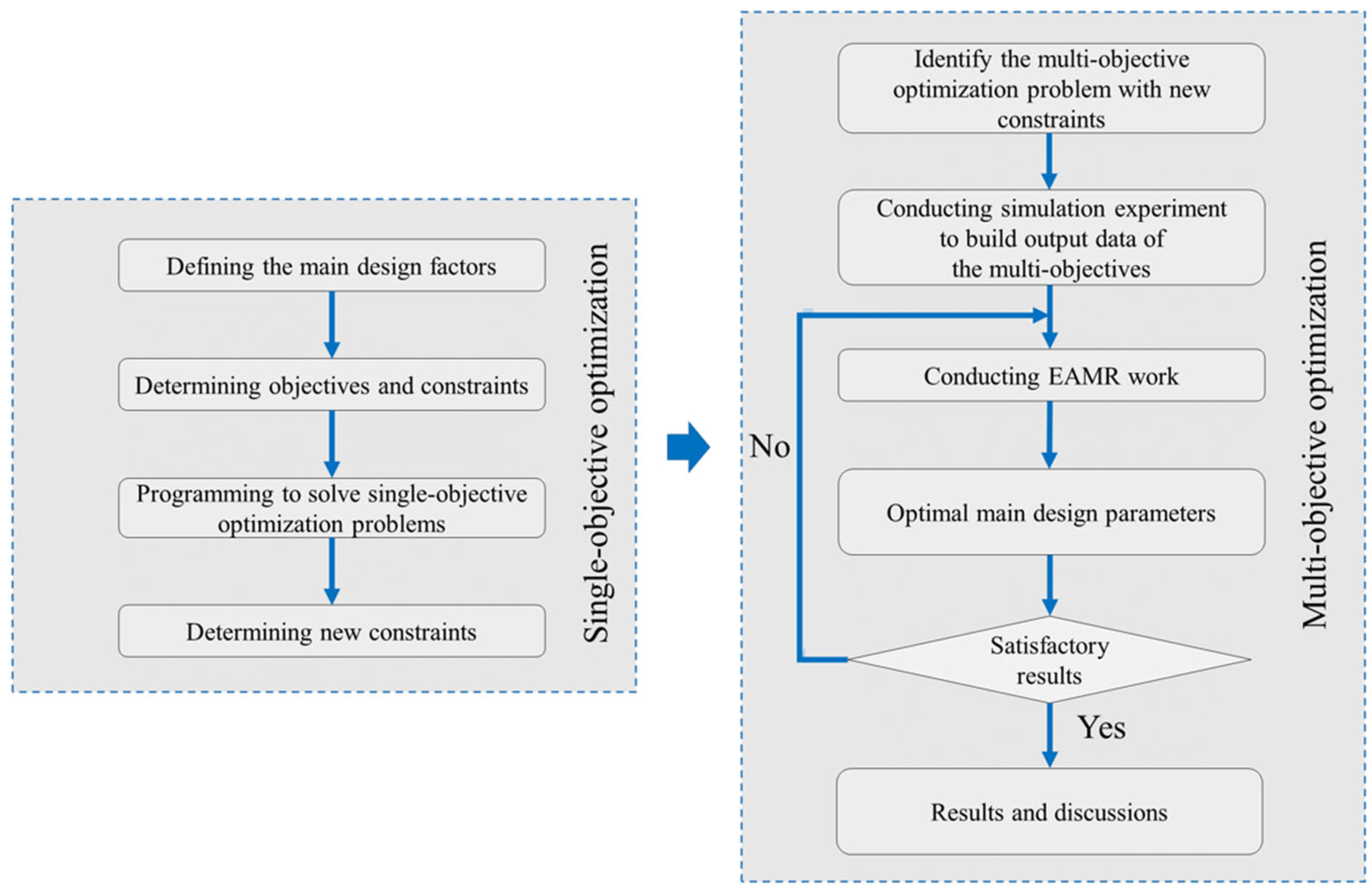
As stated in Section 2.3, three main design factors are selected as variables for the MOOP in this work. These variables are listed in Table 1, along with their lowest and maximum values. In actuality, it is challenging to address the multi-objective optimization (MOO) problem using an MCDM method. The reason for this is that there are a lot of options or potential solutions when it comes to dealing with a MOO problem. To ensure the accuracy of the parameters and avoid missing the optimization problem’s solution, the three parameters in this work have limits, as shown in Table 1, and the step between the variables is 0.02. In this case, the number of options (or experimental runs) that must be determined and compared is ( 9 1 ) / 0.02 · ( 0.4 0.25 ) / 0.02 · ( 0.4 0.25 ) / 0.02 = 22.500 (runs). Therefore, it is not viable to address the MOO problem directly using the MCDM approach due to the sheer amount of possibilities. The MAIRCA method is used to solve the MOOP in this work and find the optimal values for the three main design variables. Minimizing the gearbox volume and optimizing the gearbox efficiency are the two goals. A simulation experiment is constructed in order to address the MOOP for a TSHG with SDGSs. Furthermore, by adopting the full factorial design, the number of experiments can be increased without taking into account the budget for each experiment because this is a simulation experiment. There will be 53 = 125 experiments as a result of the three experimental variables and five levels for each variable. But out of the three variables that are listed, Table 1 shows that u1 has the widest distribution (ranging from 1 to 9). Consequently, there is a considerable difference between the levels of this variable (in this case, (9 − 1)/4 = 2), even with five levels). The values of u1 are typically rounded to the hundredths in practice. As a result, in order to make the computation easier and simpler, a way to lessen the vast distance between the variables of u1 must be found. A solution to multi-objective problems is suggested in this work (Figure 3). The following are the two components of this procedure: phase 1 factors determine the best primary design by solving the multi-objective optimization issue; and phase 2 factors minimize the gap between the levels by solving the single-objective optimization problem. Furthermore, if the levels of the variable are not sufficiently close to one another or if the best solution is not appropriate for the requirement, the MAIRCA issue will be rerun using the smaller distance between two levels of the u1 in order to solve the multi-objective problem (see Figure 3).

3.2. Method to Solve MCDM Problem

In this paper, the MCDM problem is handled via the MAIRCA technique. The following actions must be taken in order to apply this approach [47]:
-
Step 1: Building the initial matrix:
X = x 11 x 1 n x 21 x 2 n x m 1 x m n
Here, the result of criterion n in variant m is represented by xmn.
-
Step 2: Determining options based on various selections P A j through:
P A j = 1 m
-
Step 3: Calculating the t p i j elements using:
t p i j = P A j ·   w j
where i = 1, 2,…, m; j = 1, 2, …, n.
-
Step 4: Finding t r i j by:
(+)
For the gearbox efficiency objective:
t r i j = t p i j · x i j x i x i + x i
(+)
For the gearbox volume objective:
t r i j = t p i j · x i j x i + x i x i +
-
Step 5: Calculating the complete gap matrix gij by:
g i j = t p i j t r i j
-
Step 6: Determining the final values of the criteria functions, Qi:
Q i = i = 1 m g i j

3.3. Method to Find the Weight of Criteria

The weights of the criteria in this research are determined using the entropy technique. This technique can be implemented by following the steps outlined below [54].
-
Finding the indicator normalized values:
p ij = x ij m + i = 1 m x ij 2
-
Calculating the entropy of each indicator:
m e j = i = 1 m p i j × l n p i j 1 i = 1 m p i j × l n 1 i = 1 m p i j
-
Determining each indicator’s weight:
w j = 1 m e j j = 1 m 1 m e j

4. Single-Objective Optimization

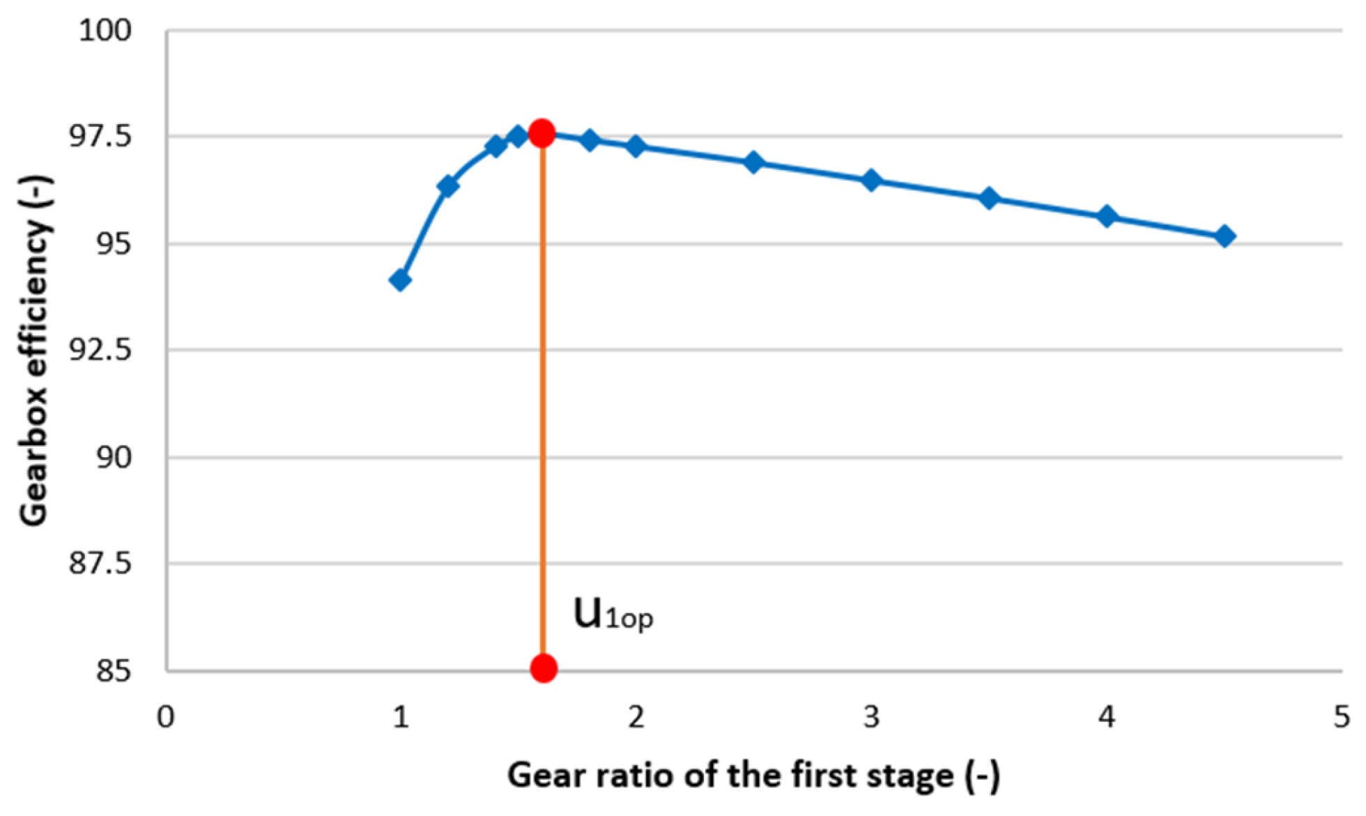
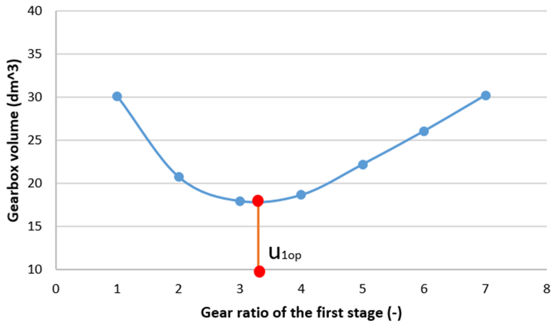
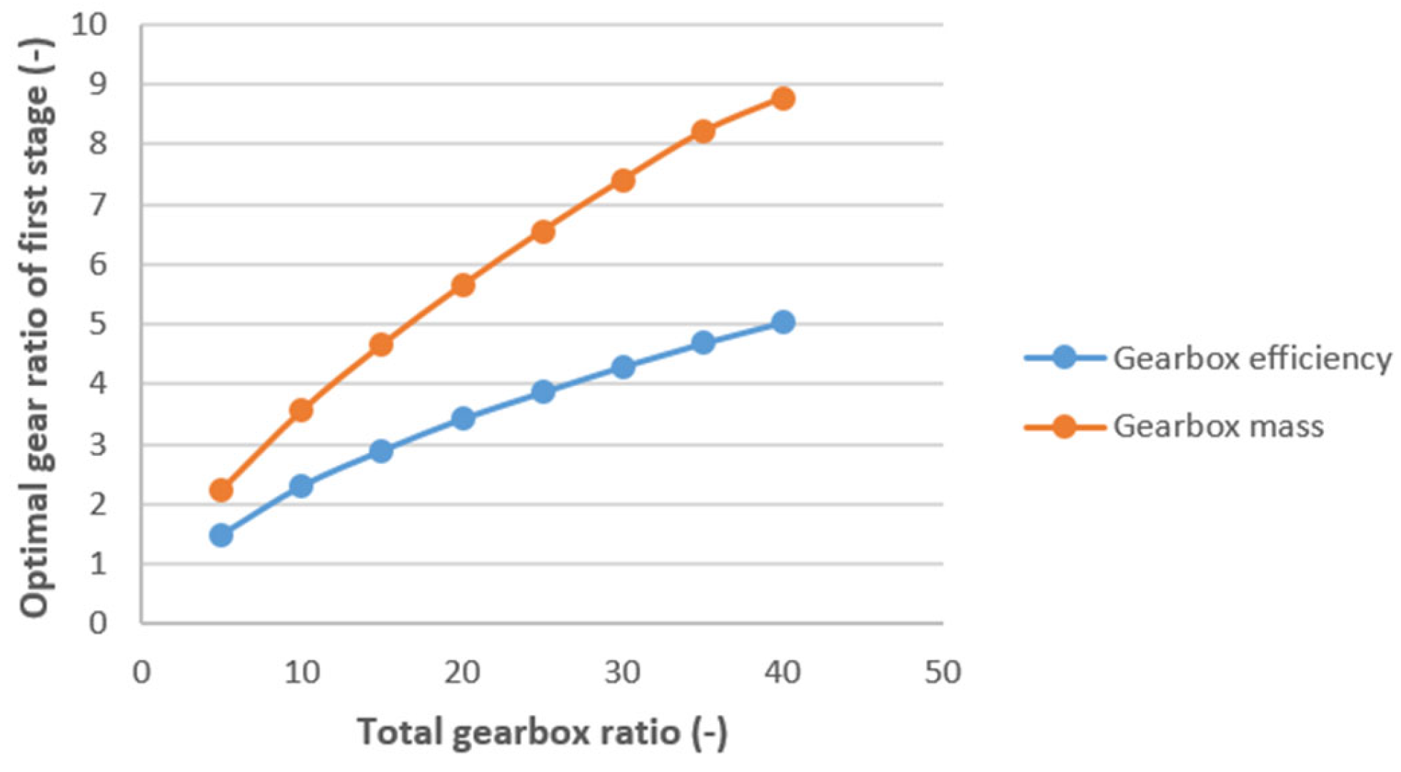
In this work, the single-objective optimization problem is solved using the direct search approach. Additionally, two single-objective tasks are solved with a MATLAB R2024a (License No. 41224477) computer program: maximizing the gearbox efficiency and minimizing the gearbox volume. The figures and observations from the program include the following. The link between ηgb and u1 is depicted in Figure 4. It is clear that for an ideal value of u1, ηgb reaches its maximum. Figure 5 shows the relationship between u1 and Vgb. It was found from the figure that Vgb reaches its minimum value when u1 is at its ideal value. The relationship between ηgb and Vgb, and ψ b a 1 and ψ b a 2 , is depicted in Figure 6 and Figure 7, respectively. Figure 6 illustrates that an increase in ψ b a 1 results in an increase in ηgb and a decrease in Vgb. As ψ b a 2 increases, both ηgb and Vgb also drop (Figure 7). The relationship between the overall gearbox ratio, ut, and the optimal gear ratio of the first stage u1 is shown in Figure 8. Additionally, Table 2 presents the newly derived constraints for the variable u1 that are calculated from the solutions of single-objective problems.

5. Multi-Objective Optimization

To conduct simulation experiments, a computer program has been developed. For the purpose of the investigation, the gearbox ratios of 10, 15, 20, 25, 30, 35, and 40 are all considered. The solutions to this ut = 35 problem are shown below. For the first 125 testing cycles, this total gearbox ratio is employed (as stated in Section 3.1). The gearbox mass and efficiency, which are the experiment’s output values, will be entered into the MAIRCA as input parameters in order to solve the MOOP. With each MAIRCA step, the gap between the two levels of each variable will decrease. For example, when ug = 35 in step 1, u1 rises from 4.58 to 8.31 (Table 2). Consequently, the distance between the two levels of u1 is (8.31 − 4.58)/4 = 0.933. Until there is less than 0.02 between the two levels of the variable, this process will be repeated. Table 3 displays the main design parameters and output responses for ut = 35 in the MAIRCA experiment’s fourth and final iteration. The weights of the criteria have been determined through the application of the entropy approach (see Section 3.3). To begin with, obtain the normalized values of pij using Equation (43). The entropy value of each indicator (mej) is found using Equation (44). Lastly, determine the weight of the criteria wj using Equation (45). For the latest MAIRCA experiment, the weights of Vgb and ηgb are found to be 0.4508 and 0.5492, respectively. Section 3.2 provides guidelines for using the MAIRCA approach for multi-objective decision-making. Adopting the measures recommended in Section 2.1, in particular, after the starting matrix is put up, the priority, or criterion PAj, is calculated by applying Equation (2). As a result, Vgb and ηgb have the same priority, which is 1/125 = 0.008. In addition, the value of parameter tpij is determined using Equation (38) and the weight of the criterion is determined in Section 2.2. The tpij values for ηgb and Vgb are 0.0036 and 0.0044, respectively. The values of trij are then obtained using Equations (39) and (40), and the values of gij are then determined using Equation (41). In the end, the values of the criteria functions Qi are determined using Equation (42). The results of the option ranking and the different parameters that the MAIRCA technique computed (for the last run of MAIRCA work) are displayed in Table 4. The table shows that option 55 is the best option out of all the options provided. Accordingly, u1 = 7.02, ψ b a 1 = 0.25, and ψ b a 2 = 0.4 are the ideal values for the primary design features (see Table 3).
The MOO problem is handled using two additional MCDM techniques, Evaluation by an Area-based Method of Ranking (EAMR) and Measurement of Alternatives and Ranking According to COmpromise Solution (MARCOS), in order to evaluate the reliability of the outcomes that are found (option 55 is the best). To determine the weights, the entropy approach is also used. When both of these methods are used to address the MOO problem, option 55 finally performs the best (see Table 5). Using all three MCDM methods, the best option, 55, is produced, demonstrating that the best option is independent of the decision-making process selected.
Continuing with the preceding discussion, Table 6 displays the ideal values for the primary design parameters that match the remaining ut values of 10, 20, 25, 30, 35, and 40. With the data in this table, the following conclusions can be drawn. Whereas ψ b a 2 chooses the greatest value ( ψ b a 2 = 0.4), ψ b a 1 chooses the lowest value ( ψ b a 1 = 0.25). This is because the smallest gearbox volume can only be produced by a small box with a cross-sectional area (LxH). This requires dw21 and dw22 to be roughly equal in order to be accomplished [55]. In addition, a larger ψ b a 2 is needed to reduce the diameter of dw22 due to the higher torque of the second stage. On the other hand, because the first stage has a lower torque, a smaller ψ b a 1 needs to be selected in order to raise dw21.
In order to evaluate the effectiveness of applying the formula for the power loss in the idle motion when calculating power loss in gears, the calculated values of the gearbox efficiency in this work are compared with the results in [33]. From Table 4 [33], when the total gearbox ratio is 7.5, the gearbox efficiency will be 99.33–99.71% (determined from input power of 10 kW, maximum output power of 9.971 kW and minimum output power of 9.933 kW). In addition, in this work, when ut changes from 10 to 40, the gearbox efficiency will have the values of 87.42–93.44% (Table 3). In fact, the efficiency of a helical gear train is 0.93–0.98 (93–98%) and the efficiency of a pair of bearings is 0.99–0.995 (99–99.5%) [51]. From these data, the efficiency of a TSHG can be determined as follows:
η g b = η g 2 · η b 3 = 0.93 2 · 0.99 3 ÷ 0.98 2 · 0.995 3 = 0.83 ÷ 0.95   or   η g b = 83 ÷ 95
By comparing the above computed values with (1), it is evident that the gearbox efficiency in this work (87.42–93.44%), is fairly close to reality (83–95%). Moreover, the gearbox efficiency in [33] (99.33–99.71%) is extremely high and not consistent with reality. This proves that using the formula to calculate the power loss in the idle motion in this work is a valuable new point and should be applied.
To evaluate the accuracy of finding the optimal values of the proposed method with other methods, like the Taguchi and Gray Relational Analysis (GRA) methods, the result of finding the optimal gear ratio of the first stage u1 in this work is compared with that in [41]. In this work, the solutions to the optimization problem, for example, u1, are found by directly comparing (over multiple steps) 22,500 values (with u1 = 1–9) to choose from (as mentioned in Section 3.1). In this case, the step between the variables of u1 is only 0.02. Meanwhile, when using the Taguchi and GRA methods, the total number of options to choose the optimal value of u1 is only 25 (Table 3 [41]). In this case, the step between the variables is 0.775 (much larger than when using the proposed method). As a result, the value u1 found using the proposed method will be more accurate than using the Taguchi and GRA methods. In other words, the proposed method is better than the Taguchi and GRA methods.
The association between the ideal values of u1 and ut is depicted in Figure 9. Additionally, it is discovered that the ideal values of u1 may be determined using the regression equation that follows (with R2 = 0.9974):
u 1 = 3.7098 · l n u t 6.0709
After finding u1, the optimal value of u2 is calculated by the following formula:
u 2 = u t / u 1

6. Conclusions

In this study, the multi-objective optimization issue associated with the design of a TSHG with a SDGSs is solved using the MAIRCA approach. The objective of the study is to determine the optimal essential design parameters that minimize the gearbox volume while maximizing the gearbox efficiency. Three crucial design elements are selected to accomplish this: the first-stage gear ratio and the CWFW for the first and second stages. Furthermore, the method of solving the multi-objective optimization issue involves two parts. Phase 2 is concerned with identifying the ideal fundamental design factors, while phase 1 is devoted to addressing the single-objective optimization issue of minimizing the difference between the variable values. This work produced the following conclusions:
By bridging the gap between the variable levels, the single-objective optimization problem speeds up and simplifies the MOOP’s solution.
-
Based on the study’s findings, the best values for the three primary design parameters of a two-stage helical gear gearbox with an SDGS ψ b a 1 = 0.2, ψ b a 1 = 0.4 and u1 determined according to (47).
-
Two individual targets are evaluated in relation to the main design parameters.
A precise solution to the MOOP can be obtained by repeatedly applying the MAIRCA technique until the desired outcomes are obtained (variables have an accuracy of less than 0.02).
-
The remarkable degree of agreement between the experimental data and the u1 model suggests that the data are reliable.

Author Contributions

The first idea was proposed by N.-P.V. and it was discussed by all the authors. With help from D.-B.V., V.-T.N. and N.-P.V. solved the optimization problem. Each author also assisted in the design of the simulation, the analysis of the experimental figures, and the interpretation of the experimental findings. With assistance from V.-T.N. and N.-P.V. wrote the manuscript. All authors have read and agreed to the published version of the manuscript.

Funding

This research received no external funding.

Data Availability Statement

The original contributions presented in the study are included in the article, further inquiries can be directed to the corresponding author.

Acknowledgments

The authors would like to thank Thai Nguyen University of Technology for their assistance with this work.

Conflicts of Interest

The authors declare that they have no conflicts of interest.

References

  1. Collins, J.A.; Busby, H.R.; Staab, G.H. Mechanical Design of Machine Elements and Machines: A Failure Prevention Perspective; John Wiley & Sons: Hoboken, NJ, USA, 2009. [Google Scholar]
  2. Höhn, B.-R.; Michaelis, K.; Hinterstoißer, M. Optimization of gearbox efficiency. Goriva I Maz. Časopis Za Tribol. Teh. Podmazivanja I Primjen. Tekućih I Plinovitih Goriva I Inžinjerstvo Izgaranja 2009, 48, 441–461. [Google Scholar]
  3. Kaya, İ.; Baykara, C. The investigation of the effect of operating conditions in gearboxes on efficiency. Adv. Mech. Eng. 2024, 16, 16878132241248072. [Google Scholar] [CrossRef]
  4. Son, G.-H.; Kim, B.-S.; Cho, S.-J.; Park, Y.-J. Optimization of the housing shape design for radiated noise reduction of an agricultural electric vehicle gearbox. Appl. Sci. 2020, 10, 8414. [Google Scholar] [CrossRef]
  5. Wang, J.P.; Liu, G.; Chang, S.; Wu, L.Y. Topology optimization of gearbox to reduce radiated noise. In Proceedings of the International Design Engineering Technical Conferences and Computers and Information in Engineering Conference, Boston, MA, USA, 2–5 August 2015; American Society of Mechanical Engineers: New York, NY, USA, 2015. [Google Scholar]
  6. Inoue, K.; Yamanaka, M.; Kihara, M. Optimum stiffener layout for the reduction of vibration and noise of gearbox housing. J. Mech. Des. 2002, 124, 518–523. [Google Scholar] [CrossRef]
  7. Pi, V.N.; Cam, N.T.H.; Hong, T.T.; Hung, L.X.; Tung, L.A.; Tuan, N.K.; Tham, H.T. Determination of optimum gear ratios of a two-stage helical gearbox with second stage double gear sets. IOP Conf. Ser. Mater. Sci. Eng. 2019, 635, 012012. [Google Scholar] [CrossRef]
  8. Van Cuong, N.; Le Hong, K.; Tran, T. Splitting total gear ratio of two-stage helical reducer with first-stage double gearsets for minimal reducer length. Int. J. Mech. Prod. Eng. Res. Dev. (IJMPERD) 2019, 9, 595–608. [Google Scholar]
  9. Pi, V.N. Optimal calculation of partial transmission ratios for four-step helical gearboxes with first and third step double gear-sets for minimal gearbox length. In Proceedings of the American Conference on Applied Mathematics, Cambridge, MA, USA, 29–32 March 2008. [Google Scholar]
  10. Marjanovic, N.; Kostic, N.; Petrovic, N.; Blagojevic, M.; Matejic, M.; Isailovic, B. Comparative Analysis of Analytical Calculation and Optimization on Gearbox Dimensions and Volume. Mach. Des. 2014, 6, 127–130. [Google Scholar]
  11. Golabi, S.; Fesharaki, J.J.; Yazdipoor, M. Gear train optimization based on minimum volume/weight design. Mech. Mach. Theory 2014, 73, 197–217. [Google Scholar] [CrossRef]
  12. Danh, T.H.; Huy, T.Q.; Danh, B.T.; Van Trang, N.; Hung, L.X. Optimization of Main Design Parameters for a Two-Stage Helical Gearbox Based on Gearbox Volume Function. In Proceedings of the International Conference on Engineering Research and Applications, Thai Nguyen, Vietnam, 1–2 December 2022; Springer: Cham, Switzerland, 2022. [Google Scholar]
  13. Milou, G.; Dobre, G.; Visa, F.; Vitila, H. Optimal design of two step gear units, regarding the main parameters. VDI Berichte 1996, 1230, 227. [Google Scholar]
  14. Cam, N.T.H.; Pi, V.N.; Tuan, N.K.; Hung, L.X.; Thao, T.T.P. A study on determination of optimum partial transmission ratios of mechanical driven systems using a chain drive and a three-step helical reducer. In Advances in Engineering Research and Application: Proceedings of the International Conference, ICERA 2018; Springer: Berlin/Heidelberg, Germany, 2019. [Google Scholar]
  15. Tuan, N.K.; Pi, V.N.; Cam NT, H.; Thao TT, P.; Thanh, H.K.; Hung, L.X.; Tham, H.T. Determining optimal gear ratios of a two-stage helical reducer for getting minimal acreage of cross section. In MATEC Web of Conferences; EDP Sciences: Les Ulis, France, 2018. [Google Scholar]
  16. Pi, V.N.; Tuan, N.K.; Hung, L.X.; Tung, L.A. A new study on determination of optimum gear ratios of a two-stage helical gearbox. In Advances in Material Sciences and Engineering; Springer: Singapore, 2020. [Google Scholar]
  17. Tu, N.T.; Ky, L.H.; Hong, T.T.; Van Cuong, N.; Tung, L.A.; Hien, B.T.; Hung, L.X. Determining optimal gear ratios of mechanical drive systems using two-stage helical gearbox with second-stage double gear sets and chain drive for minimal system cross section area. In Advances in Engineering Research and Application: Proceedings of the International Conference on Engineering Research and Applications, ICERA 2019, Thai Nguyen, Vietnam, 1–2 December 2020; Springer: Cham, Switzerland, 2020. [Google Scholar]
  18. Pi, V.N.; Tuan, N.K. Optimum determination of partial transmission ratios of three-step helical gearboxes for getting minimum cross section dimension. J. Environ. Sci. Eng. A 2016, 5, 570–573. [Google Scholar]
  19. Pi, V.N.; Ngoc, N.D.; Hong, T.T.; Linh, N.H. Cost optimization study of two-step helical gearboxes with first stage double gear sets. Int. J. Mech. Prod. Eng. Res. Dev. (Ijmperd) 2020, 10, 573–584. [Google Scholar]
  20. Danh, T.H.; Huy, T.Q.; Danh, B.T.; Tan, T.M.; Van Trang, N.; Tung, L.A. Determining Partial Gear Ratios of a Two-Stage Helical Gearbox with First Stage Double Gear Sets for Minimizing Total Gearbox Cost. In Proceedings of the International Conference on Engineering Research and Applications, Thai Nguyen, Vietnam, 1–2 December 2022; Springer: Cham, Switzerland, 2022. [Google Scholar]
  21. Quang, N.H.; Tu, N.T.; Linh, N.H.; Luan, N.H.; Anh, L.H.; Tuan, N.A.; Giang, T.N.; Pi, V.N. Determining Optimum Gear Ratios for a Four-Stage Helical Gearbox for Getting Minimum Gearbox Cost. In Proceedings of the International Conference on Engineering Research and Applications, Thai Nguyen, Vietnam, 1–2 December 2021; Springer: Cham, Switzerland, 2021. [Google Scholar]
  22. Pi, V.N.; Hong, T.T.; Ky, L.H.; Hung, L.X.; Tung, L.A.; Tuan, N.K. A study on calculating optimum gear ratios of a three-stage helical gearbox. Int. J. Mech. Eng. Technol. 2018, 9, 1392–1400. [Google Scholar]
  23. Wang, Y.; Qian, Q.; Chen, G.; Jin, S.; Chen, Y. Multi-objective optimization design of cycloid pin gear planetary reducer. Adv. Mech. Eng. 2017, 9, 1687814017720053. [Google Scholar] [CrossRef]
  24. Chong, T.H.; Bae, I.; Kubo, A. Multiobjective optimal design of cylindrical gear pairs for the reduction of gear size and meshing vibration. JSME Int. J. Ser. C Mech. Syst. Mach. Elem. Manuf. 2001, 44, 291–298. [Google Scholar] [CrossRef]
  25. Park, C.I. Multi-objective optimization of the tooth surface in helical gears using design of experiment and the response surface method. J. Mech. Sci. Technol. 2010, 24, 823–829. [Google Scholar] [CrossRef]
  26. Terán, C.V.; Martínez-Gómez, J.; Milla, J.C.L. Material selection through of multi-criteria decisions methods applied to a helical gearbox. Int. J. Math. Oper. Res. 2020, 17, 90–109. [Google Scholar] [CrossRef]
  27. Alam, J.; Panda, S. comprehensive study on multi-objective design optimization of spur gear. Mech. Based Des. Struct. Mach. 2023, 51, 5272–5298. [Google Scholar] [CrossRef]
  28. Patil, M.; Ramkumar, P.; Shankar, K. Multi-objective optimization of spur gearbox with inclusion of tribological aspects. J. Frict. Wear 2017, 38, 430–436. [Google Scholar] [CrossRef]
  29. Parmar, A.; Ramkumar, P.; Shankar, K. Optimization of Planetary Gearbox Using NSGA-II. In Recent Advances in Mechanical Engineering: Select Proceedings of ICRAME 2020; Springer: Berlin/Heidelberg, Germany, 2021. [Google Scholar]
  30. Miler, D.; Žeželj, D.; Lončar, A.; Vučković, K. Multi-objective spur gear pair optimization focused on volume and efficiency. Mech. Mach. Theory 2018, 125, 185–195. [Google Scholar] [CrossRef]
  31. Tudose, L.; Buiga, O.; Jucan, D.; Stefanache, C. Multi-objective optimization in helical gears design. In Proceedings of the Fifth International Symposium about Design in Mechanical Engineering-KOD, Novi Sad, Serbia, 15–16 April 2008. [Google Scholar]
  32. Deb, K.; Jain, S. Multi-speed gearbox design using multi-objective evolutionary algorithms. J. Mech. Des. 2003, 125, 609–619. [Google Scholar] [CrossRef]
  33. Maputi, E.S.; Arora, R. Multi-objective optimization of a 2-stage spur gearbox using NSGA-II and decision-making methods. J. Braz. Soc. Mech. Sci. Eng. 2020, 42, 1–22. [Google Scholar] [CrossRef]
  34. Sanghvi, R.C.; Vashi, A.S.; Patolia, H.P.; Jivani, R.G. Multi-objective optimization of two-stage helical gear train using NSGA-II. J. Optim. 2014, 2014, 670297. [Google Scholar] [CrossRef]
  35. Sabarinath, P.; Thansekhar, M.; Jeganathan, R.; Saravanan, R. Multi objective Design Optimization of Helical gear pair using Adaptive parameter Harmony search Algorithm. Appl. Mech. Mater. 2015, 813–814, 1032–1036. [Google Scholar] [CrossRef]
  36. Lagresle, C.; Guingand, M.; de Vaujany, J.-P.; Fulleringer, B. Optimization of tooth modifications for spur and helical gears using an adaptive multi-objective swarm algorithm. Proc. Inst. Mech. Eng. Part C J. Mech. Eng. Sci. 2019, 233, 7292–7308. [Google Scholar] [CrossRef]
  37. Korta, J.A.; Mundo, D. Multi-objective micro-geometry optimization of gear tooth supported by response surface methodology. Mech. Mach. Theory 2017, 109, 278–295. [Google Scholar] [CrossRef]
  38. Wang, H.; Chen, D.; Pan, F.; Yu, D. Multi-objective Optimization Design of Helical Gear in Centrifugal Compressor Based on Response Surface Method. IOP Conf. Series Mater. Sci. Eng. 2018, 423, 012040. [Google Scholar] [CrossRef]
  39. Liu, S.; Li, B.; Gan, R.; Xu, Y.; Yang, G. Multi-Objective Optimization of Two-Stage Helical Pairs in Helical Hydraulic Rotary Actuator Using Ensemble of Metamodels and NSGA-II. Actuators 2023, 12, 385. [Google Scholar] [CrossRef]
  40. Wu, K.; Wei, D.; Lu, R.; Huang, Q.; Xie, J.; Tang, W. Multi-objective optimization of a 2-stage helical gear transmission system using NSGA-III. In Proceedings of the 2022 IEEE 6th Information Technology and Mechatronics Engineering Conference (ITOEC), Chongqing, China, 4–6 March 2022; IEEE: Piscataway, NJ, USA, 2022. [Google Scholar]
  41. Le, X.-H.; Vu, N.-P. Multi-objective optimization of a two-stage helical gearbox using taguchi method and grey relational analysis. Appl. Sci. 2023, 13, 7601. [Google Scholar] [CrossRef]
  42. Tran, H.-D.; Le, X.-H.; Nguyen, T.-T.; Hoang, X.-T.; Trieu, Q.-H.; Vu, N.-P. Application of the Taguchi Method and Grey Relational Analysis for Multi-Objective Optimization of a Two-Stage Bevel Helical Gearbox. Machines 2023, 11, 716. [Google Scholar] [CrossRef]
  43. Huy, T.Q.; Van Binh, N.; Van Thanh, D.; Danh, T.H.; Van Trang, N. Optimization of a Two-stage Helical Gearbox with Second Stage Double Gear Sets to Reduce Gearbox Mass and Increase Gearbox Efficiency. WSEAS Trans. Appl. Theor. Mech. 2023, 18, 287–298. [Google Scholar] [CrossRef]
  44. Hung, T.Q.; Huong, T.T.T. Multi-objective Optimization of a Two-Stage Helical Gearbox to Improve Efficiency and Reduce Height. J. Environ. Sci. Eng. B 2023, 12, 236–247. [Google Scholar]
  45. Hung, T.Q.; Tung, L.A. Application of Taguchi Technique and Grey Relational Analysis for Multi-Target Optimization of Two Stage Helical Gearboxes. Eur. J. Appl. Sci. 2023, 11, 236–247. [Google Scholar]
  46. Dinh, V.-T.; Tran, H.-D.; Bui, T.-D.; Vu, D.-B.; Vu, D.; Vu, N.-P.; Truong, T.-T. Multi-Objective Optimization of a Two-Stage Helical Gearbox with Second Stage Double Gear-Sets Using TOPSIS Method. Processes 2024, 12, 1160. [Google Scholar] [CrossRef]
  47. Pamučar, D.; Vasin, L.; Lukovac, L. Selection of railway level crossings for investing in security equipment using hybrid DEMATEL-MARICA model. In Proceedings of the XVI International Scientific-Expert Conference on Railway, Railcon, Niš, Serbia, 13–14 October 2014. [Google Scholar]
  48. Pamucar, D.S.; Tarle, S.P.; Parezanovic, T. New hybrid multi-criteria decision-making DEMATELMAIRCA model: Sustainable selection of a location for the development of multimodal logistics centre. Econ. Res. Istraz. 2018, 31, 1641–1665. [Google Scholar]
  49. Gigović, L.; Pamučar, D.; Bajić, Z.; Milićević, M. The combination of expert judgment and GIS-MAIRCA analysis for the selection of sites for ammunition depots. Sustainability 2016, 8, 372. [Google Scholar] [CrossRef]
  50. Römhild, I.; Linke, H. Gezielte Auslegung Von Zahnradgetrieben mit minimaler Masse auf der Basis neuer Berechnungsverfahren. Konstruktion 1992, 44, 229–236. [Google Scholar]
  51. Chat, T.; Van Uyen, L. Design and Calculation of Mechanical Transmissions Systems, vol. 1; Educational Republishing House: Hanoi, Vietnam, 2007. [Google Scholar]
  52. Jelaska, D.T. Gears and Gear Drives; John Wiley & Sons: Hoboken, NJ, USA, 2012. [Google Scholar]
  53. Buckingham, E. Analytical Mechanics of Gears; Courier Corporation: North Chelmsford, MA, USA, 1988. [Google Scholar]
  54. Hieu, T.T.; Thao, N.X.; Thuy, L. Application of MOORA and COPRAS models to select materials for mushroom cultivation. Vietnam. J. Agric. Sci. 2019, 17, 322–331. [Google Scholar]
  55. Kudreavtev, V.N.; Gierzaves, I.A.; Glukharev, E.G. Design and Calculus of Gearboxes; Mashinostroenie Publishing: St. Petersburg, Russia, 1971. (In Russian) [Google Scholar]
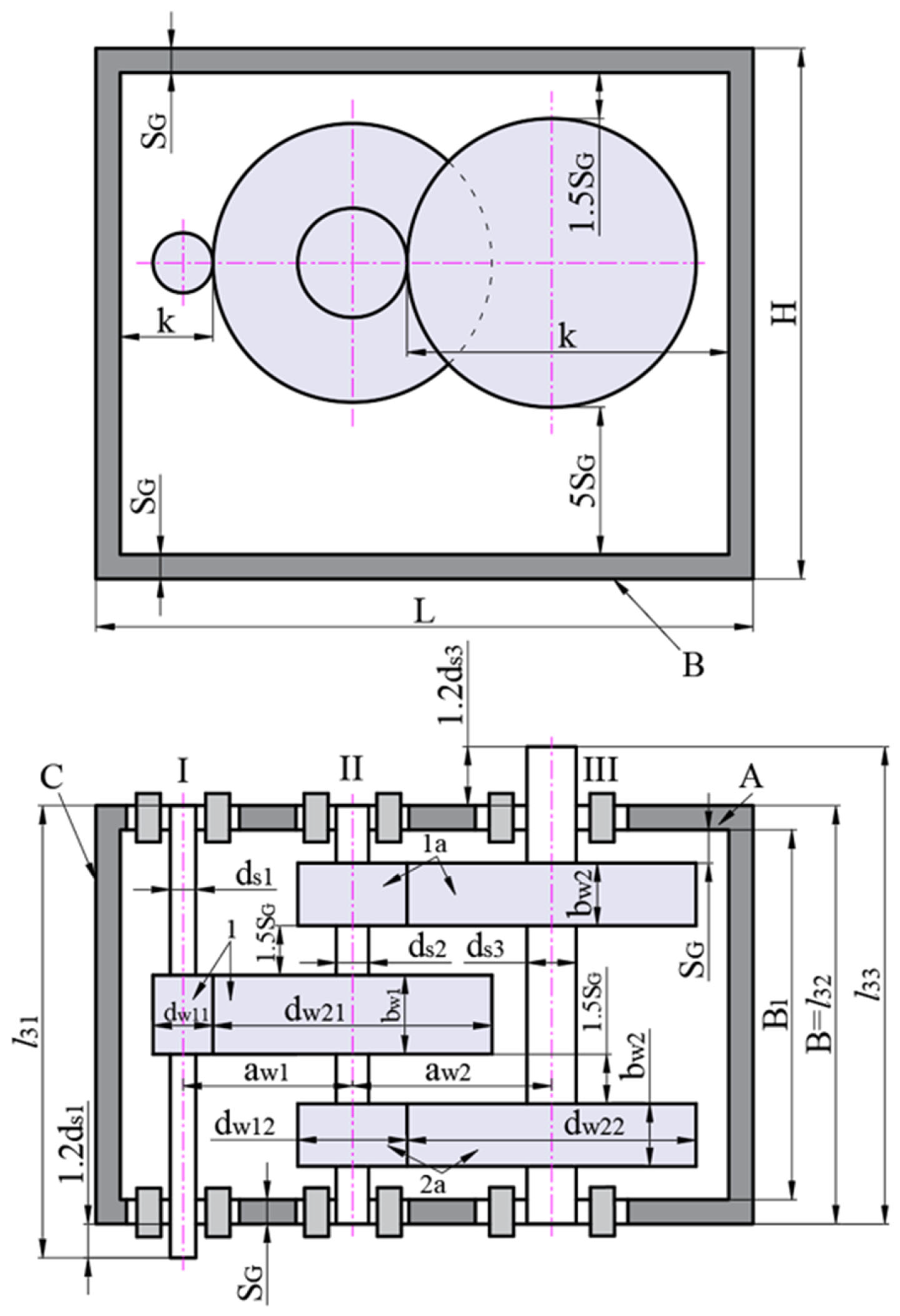
Figure 1. Two-stage helical gearbox with second-stage double gear sets.
Applsci 14 05274 g001
Figure 2. Calculated schema of the lubrication parameters.
Applsci 14 05274 g002
Figure 3. The procedure for solving the multi-objective problem.
Applsci 14 05274 g003
Figure 4. Relationship between u1 and ηgb.
Applsci 14 05274 g004
Figure 5. Relationship between u1 and Vgb.
Applsci 14 05274 g005
Figure 6. Relationship between ψ b a 1 and ηgb (a) and Vgb (b).
Applsci 14 05274 g006
Figure 7. Relationship between ψ b a 2 and ηgb (a) and Vgb (b).
Applsci 14 05274 g007
Figure 8. Optimal gear ratio of stage 1 versus the total gearbox ratio.
Applsci 14 05274 g008
Figure 9. Relationship between u1 and ut.
Applsci 14 05274 g009
Table 1. Input parameters.
ParameterSymbolLower LimitUpper Limit
Gearbox ratio of stage 1u119
CWFW of stage 1 ψ b a 1 0.250.4
CWFW of stage 2 ψ b a 2 0.250.4
Table 2. New constraints of u1.
utu1
Lower LimitUpper Limit
102.22.36
152.794.76
203.325.75
253.766.66
304.197.51
354.588.31
404.938.88
Table 3. Main design factors and output results for ut = 35 in the 4th run of the MAIRCA. The background color describes the best option.
Trial.u1 ψ b a 1 ψ b a 2 Vgb (dm3)ηgb (%)
16.990.250.2521.2393.44
26.990.250.2920.8293.38
36.990.250.3320.5293.32
46.990.250.3620.3093.26
56.990.250.4020.1293.21
66.990.290.2521.3792.26
76.990.290.2920.9392.21
267.010.250.2521.2193.42
277.010.250.2920.8193.36
287.010.250.3320.5193.30
547.020.250.3620.2793.23
557.020.250.4020.1093.18
567.020.290.2521.3592.22
717.020.400.2521.8787.72
727.020.400.2921.3487.66
737.020.400.3320.9487.60
1017.050.250.2521.1793.33
1027.050.250.2920.7793.27
1037.050.250.3320.4793.21
1237.050.400.3320.9287.53
1247.050.400.3620.6087.48
1257.050.400.4020.3587.42
Table 4. Calculated results and ranking of the options via the MAIRCA method for ut = 35. The background color describes the best option.
Trial.trijgijQiRank
VgbηgbVgbηgb
10.00160.00360.00280.00000.002854
20.00260.00360.00180.00000.001830
30.00340.00350.00100.00010.001120
40.00390.00350.00050.00010.000610
50.00430.00350.00000.00010.00023
60.00130.00290.00310.00070.003875
70.00240.00290.00200.00070.002855
260.00170.00360.00270.00000.002751
270.00270.00360.00170.00000.001829
280.00340.00350.00100.00010.001119
540.00400.00350.00040.00010.00057
550.00440.00350.00000.00020.00021
560.00130.00290.00310.00070.003873
710.00010.00020.00430.00340.0077123
720.00140.00010.00300.00350.0065118
730.00230.00010.00210.00350.0055108
1010.00180.00350.00260.00010.002746
1020.00280.00350.00160.00010.001726
1030.00350.00350.00090.00010.001016
1230.00240.00010.00200.00350.0055106
1240.00320.00000.00120.00360.004891
1250.003800.00060.00360.0042283
Table 5. Rankings of the options when using the MAIRCA, EAMR, and MARCOS methods. The background color describes the best option.
Ranking
Trial.MAIRCAEAMRMARCOS
1545565
2303538
3202020
4101010
5333
6757785
7555255
26515464
27293336
28191919
54777
55111
56737483
71123123123
72118118115
73108108108
101464859
102262731
103161616
123106106106
124919191
125838171
Table 6. Optimum values of the main design factors.
No.ut
10152025303540
u12.44.125.025.796.637.027.66
ψ b a 1 0.250.250.250.250.250.250.25
ψ b a 2 0.40.40.40.40.40.40.4
Disclaimer/Publisher’s Note: The statements, opinions and data contained in all publications are solely those of the individual author(s) and contributor(s) and not of MDPI and/or the editor(s). MDPI and/or the editor(s) disclaim responsibility for any injury to people or property resulting from any ideas, methods, instructions or products referred to in the content.