Article

Novel Ordinary Differential Equation for State-of-Charge Simulation of Rechargeable Lithium-Ion Battery

1
Group of German Research Chair, African Institute for Mathematical Sciences (AIMS), KN 3 Rd, Kigali P.O. Box 7150, Rwanda
2
Group of Process Optimization, Institute for Automation and Systems Engineering, Technische Universität Ilmenau, P.O. Box 10 05 65, 98684 Ilmenau, Germany
*
Author to whom correspondence should be addressed.
Appl. Sci. 2024, 14(12), 5284; https://doi.org/10.3390/app14125284
Submission received: 11 April 2024 / Revised: 6 June 2024 / Accepted: 13 June 2024 / Published: 18 June 2024

Abstract

:
Lithium-ion battery energy storage systems are rapidly gaining widespread adoption in power systems across the globe. This trend is primarily driven by their recognition as a key enabler for reducing carbon emissions, advancing digitalization, and making electricity grids more accessible to a broader population. In the present study, we investigated the dynamic behavior of lithium-ion batteries during the charging and discharging processes, with a focus on the impact of terminal voltages and rate parameters on the state of charge (SOC). Through modeling and simulations, the results show that higher terminal charging voltages lead to a faster SOC increase, making them advantageous for applications requiring rapid charging. However, large values of voltage-sensitive coefficients and energy transfer coefficients were found to have drawbacks, including increased battery degradation, overheating, and wasted energy. Moreover, practical considerations highlighted the trade-off between fast charging and time efficiency, with charging times ranging from 8 to 16 min for different rates and SOC levels. On the discharging side, we found that varying the terminal discharging voltage allowed for controlled discharging rates and adjustments to SOC levels. Lower sensitivity coefficients resulted in more stable voltage during discharging, which is beneficial for applications requiring a steady power supply. However, high discharging rates and sensitivity coefficients led to over-discharging, reducing battery life and causing damage. These new findings could provide valuable insights for optimizing the performance of lithium-ion batteries in various applications.

1. Introduction

Rechargeable lithium-ion batteries are widely used as a power source in many industrial sectors ranging from portable electronic devices to electric vehicles and power grid systems [1,2,3]. In the context of energy management and distribution, the rechargeable lithium-ion battery has increased the flexibility of power grid systems, because of their ability to provide optimal use of stable operation of intermittent renewable energy sources such as solar and wind energy [4,5,6]. In addition to storing renewable energy for later use, lithium-ion batteries are the major component dictating the performance of electric vehicle (EV) performance. Furthermore, their integration into EVs offers a promising solution to reducing CO2 emissions.
Rechargeable lithium-ion batteries offer many opportunities, such as high power density, long life cycle [7,8], higher cell voltages [9,10], lower maintenance requirements [11,12], higher charging speeds with lower self-discharging rates [13,14], and no memory effect compared with the previous generations of rechargeable batteries [15]. However, even if the rechargeable lithium-ion battery seems to provide a suitable solution to the limitations of renewable energy production and utilization, there are also some existing issues related to its technology. More explicitly, one of the fundamental problems with this device is battery management systems (BMSs) [16], and among all the parameters of BMSs, state of charge was found to be the most significant parameter [17,18]. The state of charge is one of the crucial evaluation parameters of BMSs that confirms the optimal charging or discharging profiles of batteries [2]. Moreover, the state of charge describes the remaining capacity in a battery energy storage system and is indicated in the form of a percentage, [ % ] . Meanwhile, one can identify the charging or discharging status of a battery by checking its SOC value [19,20]. High precision in state-of-charge estimation is a must for power battery control strategies [21,22]. Indeed, to ensure the optimal charging/discharging profiles of the battery, the SOC should satisfy the following condition:
S O C m i n S O C ( t ) S O C m a x ,
where S O C m i n is the minimum state of charge and S O C m a x is the maximum state of charge. These conditions play an important role when designing a controller to decide when to charge and when to discharge a battery [2]. Furthermore, these box constraints on the state of charge also help the controller to cut off the power to prevent the battery from damage due to over-discharging and overcharging [23]. In ref. [24], for instance, it is reported that the overcharging of lithium-ion batteries leads to the generation of dendrites due to the deposition of lithium ions, which induces the generation of a large amount of heat due to internal short circuit, and the vaporization of the electrolyte solution. Another research work published has shown experimentally that when the lithium-ion battery is discharged to the cut-off voltage and then forced to discharge more than 20 % of the state of charge, it will cause irreversible internal short-circuit damage to the battery [25,26]. In this respect, the authors concluded that the possibility of short circuit has a non-linear relationship with the depth of over-discharging.
In general, determining the SOC of rechargeable lithium-ion batteries is a complex task, due to the non-linear reaction dynamics caused by the electrochemical characteristics of lithium-ion batteries [27,28]. This means that the SOC can only indirectly be calculated by measuring some physical parameters, such as charge/discharge current, terminal voltage, and internal resistance [29], or by using a mathematical model and algorithm [30,31]. However, the physical parameters of lithium-ion batteries are usually affected by some uncertain factors, such as the open-circuit voltage ( U o c ) of the battery, temperature variation, battery aging, and overall efficiency of the battery systems [32]. This induces strong non-linear behavior in battery systems, which significantly increases the difficulty of estimating the battery state of charge. Therefore, accurately estimating the state of charge is crucial to keeping the lithium-ion battery working under safe conditions and maximizing its performance.

2. Some Existing Methods of Estimating the Lithium-Ion Battery State of Charge

At present, battery state-of-charge estimation methods can be divided into three categories, namely, experimental methods, data-driven methods, and model-based methods [33,34,35].

2.1. Experimental Methods

Experimental methods refer to the methods to explore battery characteristics through battery experiments. The first experimental method is referred to as the Coulomb counting method [36]. This technique estimates the SOC in the battery by integrating the current transferred to the battery over time, to determine the remaining charge relative to the maximum battery state of charge. Coulomb counting is often utilized in combination with model-based methods due to its relatively simple implementation. However, this method suffers from inaccuracies due to sensor error accumulation and initial value errors; moreover, it is only suitable for online applications [37,38]. The second experimental method is the so-called Hybrid Pulse Power Characterization (HPPC) [39]. This method consists of monitoring voltage variations during short-/high-current charge/discharge pulses with relaxation periods. In this method, the cell voltage response is affected by the electrochemical kinetics of the battery, such as ohmic losses, double-layer capacity, and lithium-ion diffusion [40,41]. The third existing experimental method is Electrochemical Impedance Spectroscopy (EIS), which measures the current and voltage relationship over a frequency range and can be used to model kinetic battery processes through the impedance spectrum and estimate physical properties like diffusion coefficients and reaction rates. Impedance Spectroscopy (EIS) requires linearity, stability, and causality, which makes it challenging to implement as an online method [42]. The experimental methods alone are more suitable for offline state-of-charge estimation due to the required experimental conditions.

2.2. Data-Driven Method

Data-driven approaches are model-free black-box methods that, for a given dataset, can provide rapid and accurate results given enough training data. These applications are the fruit of outstanding progress in machine learning in the recent past, which has motivated a renewed interest in applying data-driven algorithms to the field of the battery state-of-charge estimation. Indeed, data-driven methods take temperature as an input characteristic, which avoids the establishment of a new thermal coupling model. Nevertheless, in the studies of ref. [43], the authors utilized a BP neural network to estimate the state of charge of lithium-ion batteries. In this regard, the estimation error of the state of charge was around 5 % . On the other hand, the work performed in ref. [44] proposed another method to estimate the battery state of charge using Support Vector Machine (SVM). In this case, the authors established an average error of 3 % . Furthermore, ref. [45] proposed the use of LS-SVM to correct the cumulative error of the ampere-hour integration method, which favors online state-of-charge estimation. However, these approaches do not take into consideration the issue of the number of training data. Thus, the work of ref. [46] suggests that using an LSTM method to estimate the state of charge can reduce the demand for training data for modeling to some extent. However, in modeling state-of-charge estimation under different conditions, data-driven methods, including RNNs, do not have great advantages. Generating sufficient training data is important but difficult because battery cell chemistry can change at any time, making existing training data non-representative.

2.3. Model-Based Methods

Model-based methods attempt to model battery behavior by incorporating physical and chemical principles into mathematical equations to accurately estimate the state of charge [47]. The authors in ref. [2] reported that state-of-charge models that define battery capacity in units of energy (kWh) are classified as energy reservoir models (ERMs). Those that define it in units of charge (Ah) are classified as charge reservoir models (CRMs), and those that define it in units of concentration (mol/L) are classified as concentration-based models.
The model-based approach involves the use of electrochemical, electrical, or a combination of both models to describe the battery dynamics from which the state of charge is estimated. The electrical model employs an approximate equivalent circuit to represent battery dynamics, and it incorporates adaptive filter algorithms like the Kalman Filter (KF), as referenced in [31]. In this approach, constructing the circuit models involves arranging various circuit elements in series, parallel, or combinations thereof to mimic the battery’s dynamic behavior. Several equivalent circuit models have been proposed, including the Rint model, the RC model, and the Thevenin model, as discussed in [1,2]. These models include a critical component, a voltage source, which signifies the Open Circuit Voltage (OCV) of the battery. The OCV, in turn, depends on the battery SOC. It is essential to note that the accuracy of SOC estimation is heavily impacted by the specific equivalent circuit model chosen to represent the battery. For SOC estimation within the electrical model, the Extended Kalman Filter (EKF) is utilized. The EKF is an enhanced version of the Kalman Filter (KF) designed for estimating the internal state of non-linear dynamic systems, using a state-space model, as described in [48]. Essentially, it predicts the future state of the system based on prior data. The EKF encompasses two key equations. One equation involves matrices constructed by using equivalent circuit model (ECM) parameters, along with the system SOC, measurable input matrices, and non-measurable process noise. The parameters are identified through standard testing procedures. The second equation is the measurement equation, which relates the output voltage to the system state vectors, measurable input matrices, and measurement noise. In the context of SOC estimation, the EKF leverages advanced battery cell models and demands relatively high computational resources. Furthermore, the electrical model’s performance relies on capacitance and resistance values that are influenced by factors like state of charge, current, or temperature. This necessitates conducting numerous experiments to establish the relationships among these parameters, as mentioned in [49]. To enhance the accuracy of the battery equivalent circuit model, researchers, as highlighted in the papers [50], often consider temperature effects and develop thermal coupling models. However, this approach increases the complexity of the model and introduces errors in the state-of-charge estimation.
The electrochemical model uses partial differential equations (PDEs) to describe battery dynamics [51]. Indeed, one of the widely used electrochemical models is the pseudo-2-D (P2D) model (refs. [52,53]), which is a set of six partial differential equations, coupled with algebraic constraints. The P2D model takes current as its input and returns voltage as its output. The partial differential equations used in the P2D model incorporate the following parameters [53]:
  • Electrolyte lithium-ion diffusion equations in the positive electrode, negative electrode, and separator according to Fick’s second law.
  • Solid-phase lithium-ion diffusion equations in the electrodes due to Fick’s second law.
  • Electrolyte ohm equations in the electrodes and separator.
  • Solid-phase ohm equations in the positive electrode and negative electrode.
  • Charge conservation equations, including a positive electrode and a negative electrode, and a separator.
  • Butler–Volmer (BV) kinetic equations at the surface of the particles in the electrodes.
However, the P2D model suffers from a notable drawback stemming from its intricacy, primarily because it incorporates a multitude of partial differential equations (PDEs) and boundary conditions. This heightened complexity significantly escalates the computational workload involved. Furthermore, the substantial computational demands associated with the application of state and parameter estimation algorithms to the PDAEs (partial differential algebraic equations) forming the P2D model make it challenging to implement these electrochemical models in real-time applications (as referenced in [54,55]). State-of-charge estimation from the full P2D model using a modified Extended Kalman Filter (EKF) has been reported in [56], where the electrochemical model is solved by the Chebyshev orthogonal collocation method to reduce the computational burden of the battery P2D electrochemical model. However, parameter estimation of the model remains a significant challenge [18]. To address this challenge, previous efforts have been made to estimate the state of charge of lithium-ion batteries by using simplified PDE-based models, such as the Single-Particle Model (SPM) and the Single-Particle Model with Electrolyte Dynamics (SPME) (as mentioned in [57,58,59]). These endeavors aimed to reduce the computational complexity associated with the P2D electrochemical model’s extensive set of PDEs. An important drawback of these simplified models is their limited suitability for scenarios involving higher C-rates. It has been observed, as highlighted in references [60], that these models begin to lose their accuracy when C-rates surpass 0.5 C. Additionally, it is worth noting that the Single-Particle Model with Electrolyte Dynamics (SPME) captures less cell dynamics for its performance assessment. However, the set of PDEs that form a P2D model requires a lot of development and computation time in online battery state-of-charge estimation [18]. In this respect, it is crucial to develop a new mathematical model that is suitable for real-time implementation of lithium-ion battery state of charge. Recently, the critical review of three mathematical models, namely, the energy reservoir model, the reservoir of charge model, and the concentration-based model for determining the evolution of the lithium-ion battery state of charge was provided to the power systems research community by Rosewater et al. in their work [2], where they used these models to calculate the optimal timing of a battery energy storage system for a peak-shaving application. The authors highlighted the advantages and disadvantages of each model from a computational point of view but mainly looked at references outside the typical applications of grid-level battery energy storage systems. However, their models do not directly incorporate the initial state of charge into the dynamic state-of-charge equation of the battery, nor the nominal and terminal voltages of the battery.
Although, as we have already stressed above, batteries are essential in modern applications because of their power and energy density, incorrect charging and discharging can impair their performance and cause breakdowns. A battery management system (BMS) is, therefore, essential for their smooth operation. SOC estimation is a key element of any battery management system and is essential to maintaining the health and efficiency of the battery. In this respect, the contribution of this paper is to provide a new mathematical model to simulate the state of charge of a lithium-ion battery, taking into account the efficiency, charge transfer coefficient, nominal voltage, and terminal voltage during the charging and discharging processes. To do so, we consider certain approximations in each modeling stage and discuss their physical meaning and characteristic units. Our proposed model assumes a one-dimensional anisotropic energy reservoir box in the 12-volt battery system, taking into account various parameters, such as battery length, energy reservoir cross-sectional area, nominal voltage, and battery voltage, during the charging and discharging processes. We numerically solve our models by using a fourth-order Runge Kutta algorithm implemented in Lunix and generate a global state-of-charge map for different sets of characteristic values of the model parameters. We assume charging and discharging efficiencies of 80 % and 95 % , respectively.
The remainder of this paper is organized as follows: In Section 3, an energy reservoir model configuration of a rechargeable lithium-ion battery is presented. In Section 4, we present a detailed exposition of our models. Section 5 presents a case study and discusses the results obtained from the numerical implementation of these models. In Section 6, we summarize and highlight the importance of meticulously choosing operational parameters to balance fast charging and discharging time efficiency.

3. Model Configuration of a Rechargeable Lithium-Ion Battery

This work considers a rechargeable lithium-ion battery to be a power–energy reservoir model, and the detailed structure is illustrated in Figure 1. In this simplified model configuration, x R is the one-dimensional spatial coordinate, L R + is the total length of the energy storage reservoir (i.e., yellow box), H R + is the cross-sectional area of the energy reservoir, E c h is the inlet energy within the battery, and E d i s is the outlet energy from the battery system.

4. Methods

4.1. Mathematical Modeling of Rechargeable Lithium-Ion Battery State of Charge

Mathematical modeling plays an important role in gaining in-depth knowledge of the dynamic behavior of rechargeable lithium-ion batteries, ultimately leading to improvements in their operational efficiency. By using the above power–energy reservoir model presented in Figure 1, the energy balance equation for the lithium-ion battery during charging/discharging can be modeled by Equation (2), which includes the entire process in the spatial domain: x [ 0 , L ] .
H L β c h P c h + P d i s β d i s = H L κ d q d t + U b C 0 γ ( μ ± q ) .
To be more explicit, Equation (2) can help to capture charging or discharging scenarios, depending on the specific conditions applied, which we will provide later. In this framework, key parameters such as P c h and P d i s quantify the rate of transfer of electrical energy into and out of the battery, while β c h and β d i s characterize the efficiency of charging and discharging, respectively. The voltage U b is the terminal voltage of the battery when it reaches its fully charging or discharging state, while q designates, under specific conditions, the state of charge added during charging or the state of charge removed during discharging so that ( κ d q / d t ) indicates the contribution of the flow of energy stored or supplied per unit time, where κ signifies the energy capacity of the energy reservoir box. Furthermore, C 0 represents the standard capacity, γ is the constant parameter that governs the energy transfer, and μ stands for the initial state of charge when the battery is neither charging nor discharging. In the term ( μ ± q ) , the plus sign (+) means that we are in a charging condition, while the minus sign (−) means that we are in a discharging condition. The reason why P c h is multiplied by β c h is that when a battery is charged, not all the energy supplied is stored; some is lost in the form of heat due to internal resistance and other inefficiencies. The charging efficiency β c h reflects the fraction of the energy supplied that is stored in the battery. If one supplies P c h to the battery, the amount of energy stored in the battery is
P s t o r e = β c h × P c h .
This means that only a part of the input power is effectively converted into stored energy. The parameter P d i s is divided by β d i s because when discharging a battery, not all the stored energy can be converted back into useful output power; again, some of it is lost as heat due to inefficiencies. The discharging efficiency β d i s indicates the fraction of the stored energy that can be converted into useful output power. If the battery discharges power at a rate of P d i s , the amount of stored energy consumed from the battery is
P c o n s u m e d = P d i s β d i s .
This formula considers that more energy needs to be drawn from the battery than is available as useful output power due to losses during the discharging process. The parameters and units in Equation (2) are summarized in Table 1.
The charging and discharging power in Equation (2) can be expressed as the rates of change in energy with respect to time, as evidenced by Equations (5) and (6):
P c h = d E c h d t ,
P d i s = d E d i s d t .
The negative sign in Equation (6) indicates that discharging power ( P d i s ) is the rate at which energy ( E d i s ) is released from the battery over time. Substituting Equations (5) and (6) into Equation (2) yields
κ d q d t + U b C 0 γ ( μ ± q ) β c h d E c h d t + 1 β d i s d E d i s d t = 0 .
To assess the efficiency of the charging and discharging processes, we correlate the rate at which energy is delivered to the battery during charging (see Equation (8)) and the rate at which energy is delivered from the battery during discharging (see Equation (9)), both as a function of energy. This correlation provides valuable insights into the overall performance and efficiency of the energy transfer processes involved in the battery’s charging and discharging cycles.
d E c h d t = U c h C 0 d q d t ,
d E d i s d t = U d i s C 0 d q d t ,
where U c h and U d i s are charging and discharging voltages, respectively.
By replacing Equations (8) and (9) into Equation (7), we obtain
κ β c h U c h C 0 + U d i s C 0 β d i s d q d t + U b C 0 γ ( μ ± q ) = 0 .
where U c h is the voltage supplied to the battery during charging, and U d i s is the voltage delivered by the battery to the load during discharging. As we have already stressed above, Equation (10) can, under specific conditions, describe either the dynamics of the state of charge of a lithium-ion battery during the charging or the discharging processes. To satisfy this condition, we should have U d i s = 0 during the charging process and U c h = 0 during the discharging process. Moreover, the form of U b should be well defined. To follow the ultimate goal of the present study, we conceived the battery terminal voltage as an empirical function of S O C ( t ) . Therefore, depending on the battery operation conditions, U b will take the form
U b c h = A S O C ( t ) S O C ( t ) 0.01 ( during charging ) ,
U b d i s = B S O C ( t ) S O C ( t ) 0.01 ( during discharging ) ,
where A and B represent the sensitivity coefficients of the variation in terminal voltage during the charging and discharging periods, respectively.

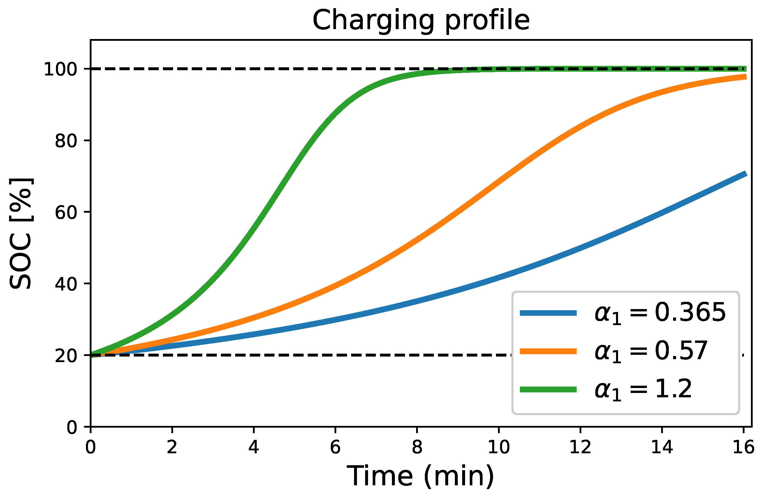
4.2. Charging Process Condition

Equation (10), to simulate the charging process, should take the following form:
κ β c h U c h C 0 d q i n t d t + U b c h C 0 γ 1 ( μ 1 + q i n t ) = 0 ,
where q i n t is the inlet state of charge that should be added to increase the battery state-of-charge level. The battery will reach the full charging state when
S O C ( t ) = μ 1 + q i n t q i n t = S O C ( t ) μ 1 .
To maintain the SOC in [%], we consider that 0.01 = 1 % and the new expression of U b c h obtained from Equation (11) is introduced with Equation (14) into Equation (13) to provide
κ β c h U c h C 0 d d t ( S O C ( t ) μ 1 ) + C 0 γ 1 A S O C ( t ) S O C ( t ) 1 S O C ( t ) = 0 .
Rearranging Equation (15) yields
d S O C ( t ) d t α 1 1 S O C ( t ) S O C 2 ( t ) = 0 ,
where
α 1 = γ 1 A V n β c h U c h , and V n = κ C 0 .
In Formula (17), V n is the nominal voltage of the battery. Moreover, α 1 represents the charging rate of the battery. It indicates how quickly the battery is being charged. A higher value of α 1 means a faster charging rate, while a lower value means a slower charging rate. To solve Equation (16), the initial condition which represents the initial state of the battery should be given. In fact, at t = 0 , when the charging process has not yet started, the battery is in the following state:
S O C ( 0 ) = ( μ 1 + q i n t ) ( 0 ) = μ 0 + q i n t ( 0 ) .
However, when the charging process has not yet started, we assume that q i n t ( 0 ) = 0 and μ 0 = 20 % . It follows from this that the initial condition of Equation (16) is
S O C ( 0 ) = μ 0 = 20 % .

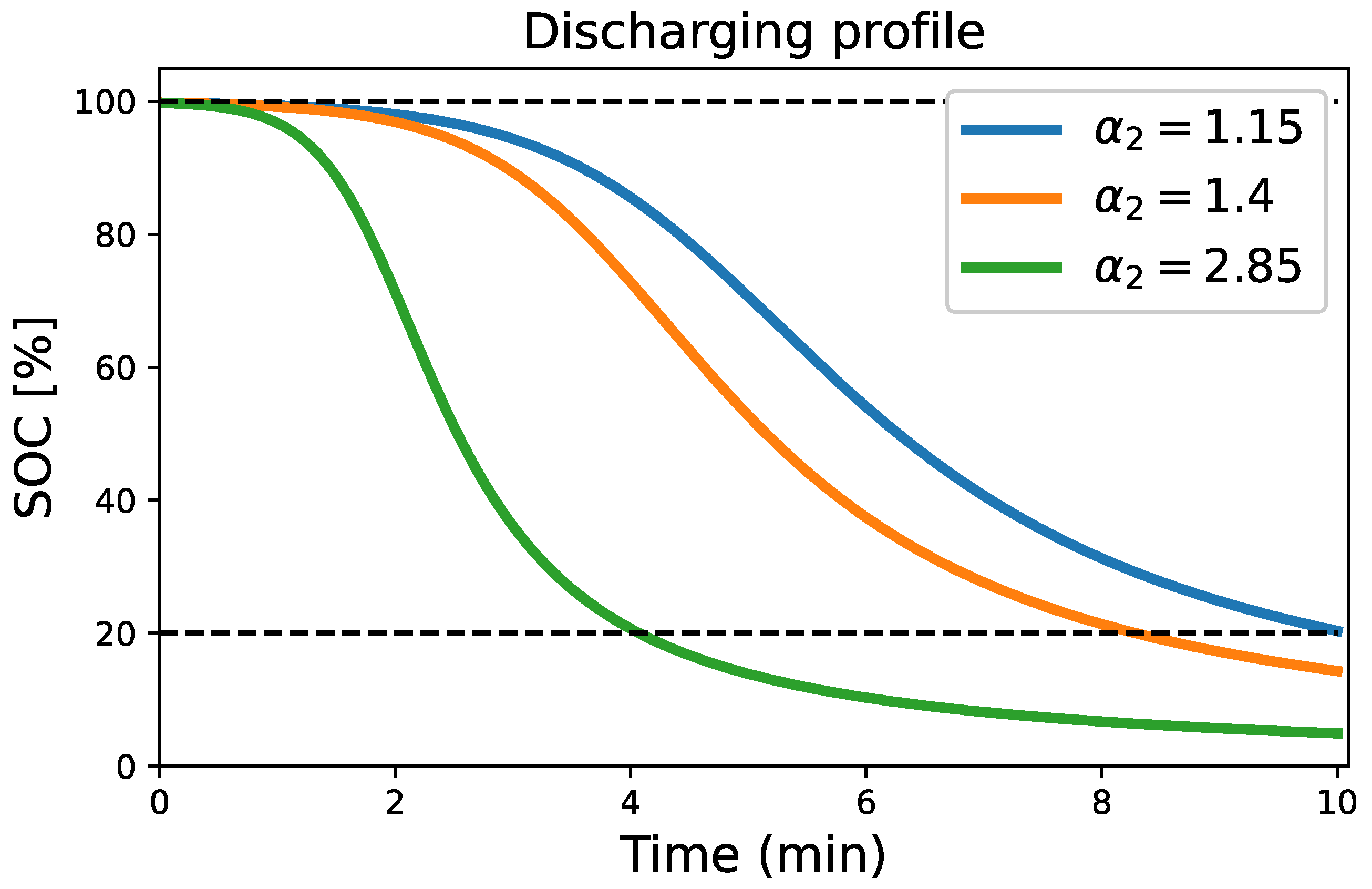
4.3. Discharging Process Condition

To simulate the discharging process, Equation (10) will now take the form
κ + U d i s C 0 β d i s d q o u t d t + U b d i s C 0 γ 2 ( μ 2 q o u t ) = 0 ,
where q o u t denotes that the battery state of charge is diminishing (i.e., q o u t < μ 2 ). Furthermore, the battery will reach the discharging state when
S O C ( t ) = μ 2 q o u t q o u t = μ 2 S O C ( t ) .
Substituting Equation (20) into Equation (19) yields
κ + U d i s C 0 β d i s d d t μ 2 S O C ( t ) + U b d i s C 0 γ 2 S O C ( t ) = 0 .
As μ 2 is a constant, Equation (21) can be written in the form
κ + U d i s C 0 β d i s d S O C ( t ) d t B C 0 γ 2 1 S O C ( t ) S O C 2 ( t ) = 0 .
It follows from this that
d S O C ( t ) d t + α 2 1 S O C ( t ) S O C 2 ( t ) = 0 ,
where
α 2 = β d i s γ 2 B β d i s V n + U d i s , and V n = κ C 0 .
In Equation (24), α 2 represents the rate of discharging of the battery. It indicates the rate at which the battery is discharged. In addition, a higher value of α 2 means a faster rate of discharging, while a lower value means a slower rate of discharging.
As in the case of the equation that simulates the charging process, we also need the initial condition to solve Equation (23). In fact, when the battery has not yet started to discharge, we have
S O C ( 0 ) = μ 2 q o u t ( 0 ) S O C ( 0 ) = μ 100 q o u t ( 0 ) .
However, as in the case of the charging condition when the discharging of the battery has not yet started, we assume that q o u t ( 0 ) = 0 and μ 100 = 100 % . It follows from this that the initial condition to solve Equation (23) is
S O C ( 0 ) = μ 100 = 100 % ,
where the subscript 100 means that the battery starts its discharging process from the state of charge S O C ( 0 ) = 100 .

4.4. Comparison of Developed Model with Old Model

The work of [2] has provided a critical review of battery energy storage systems to the power systems research community. In their work, the authors present different types of energy reservoir models and highlighted the advantages and disadvantages of each model from a computational point of view. However, their models do not directly incorporate the initial state of charge or the nominal and terminal voltages of the battery into the dynamic state-of-charge equation of the battery which we have taken into account in our model. The simplicity of the model derived in the present study lies in the fact that the battery can be considered an energy reservoir in which energy is stored and then withdrawn for consumption in the electricity distribution system. In addition, the charging and discharging dynamic models we have provided in our Equations (16) and (23) are advantageous because they do not involve complex mathematical terms and there is no need to distinguish the elementary electrochemical units or the type of electrochemistry inside the battery as presented in [54]. Another advantage of the models we propose is that the initial state of charge of the battery is directly integrated into the mathematical model, and so are the nominal and terminal voltages of the battery. The control variables of these models are the terminal charging voltage U b c h and the terminal discharging voltage U b d i s , while the state of charge is the only state variable. It is important to note that our proposed model accounts for the presence of losses during the charging and discharging cycles, which are quantified by the separate energy efficiency factors, β c h and β d i s , assigned to each operation. In particular, the model formulated in this study provides a new theoretical framework for understanding the complex interaction of battery terminal voltage in the dynamic equations governing the state of charge. Some important parameters of the model are listed in Table 2.

5. Case Study

As a case study, the model developed in the present work is applied to a 12-volts lithium-ion battery. In fact, for this type of battery, the terminal voltage varies during charging and discharging, and its sensitivity coefficient reflects how it changes in response to current flow. The charging terminal voltage increases from 13.2 V to 14.6 V as energy is stored, while the discharging terminal voltage decreases from 12.9 V to 12 V as energy is released. Furthermore, the energy transfer coefficient characterizes the efficiency of energy conversion from electrical to chemical forms during charging or from chemical to electrical forms during discharging processes. All these parameter variations influence the battery SOC. Therefore, we have chose to vary these parameters in the finite range in the case of charging and discharging, and the results are summarized in Table 3 and Table 4.
Figure 2 shows the evolution of the state of charge, S O C ( t ) , of the lithium-ion battery as a function of time for different values of the rate of charging α 1 and for V n = 12.8 V, U c h = 14.6 V, β c h = 80 % , and μ 0 = 20 % . Each curve corresponds to α 1 = 0.365 (blue curve), α 1 = 0.57 (orange curve), and α 1 = 1.2 (green curve). In Figure 2, we observe that at higher terminal charging voltages U b c h , voltage-sensitive coefficients A and energy transfer coefficients γ 1 lead to faster increases in time, making them advantageous for applications requiring fast charging. However, it should be noted that large values of these parameters can lead to drawbacks, such as increased battery degradation, overheating, and wasted energy. In addition, practical consideration of charging time, which varies from 8 min at a charging rate of 1.2 for S O C = 100 % to 16 min at rates of 0.365 and 0.57 for S O C = 70 % and S O C = 99 % , respectively, highlights the trade-off between fast charging and time efficiency. These results are summarized in Table 3.
Figure 3 shows the discharging profile of the lithium-ion battery as a function of time for different values of discharging rate α 2 and for V n = 12.8 V, U d i s = 12 V, β d i s = 95 % , and μ 100 = 100 % . Indeed, Figure 3 suggests that varying the terminal discharging voltage U b d i s allows the discharging process to be controlled. More explicitly, a particular feature of these results that emerges from the numerical simulations of Equation (23) is the observation that a higher terminal voltage (i.e., 12.9 V) results in a slower discharging rate α 2 = 1.15 , which can be advantageous when a longer battery life is desired. This variation allows the S O C to be adjusted to the desired level (i.e., 20 % ). In addition, setting the sensitivity coefficient (B) affects how the voltage reacts to variations in S O C . A lower B value (see, for example, B = 3.395 × 10 2 ) results in lower sensitivity, giving a more stable voltage during discharging. This can be advantageous for applications requiring a steady power supply. However, a high γ 2 leads to excessive discharging, as observed when α 2 = 2.85 . This can significantly reduce battery life and damage the battery. In addition, a higher α 2 (for example, 2.85 ) leads to rapid discharging, resulting in over-discharging to 9 % SOC after 4 h. These results are summarized in Table 4.

6. Conclusions

This study provided valuable insights into the dynamic behavior of lithium-ion batteries during both the charging and discharging processes. We observed that varying terminal voltages, sensitivity coefficients, and energy transfer coefficients significantly impact the SOC and discharging rates. Higher terminal charging voltages, as demonstrated by our results, can lead to faster SOC increases, making them advantageous for applications requiring rapid charging. However, it is crucial to strike a balance, as excessive values of these parameters can result in battery degradation, overheating, and energy wastage. On the other hand, in the discharging process, a higher terminal voltage leads to a slower discharging rate, which is beneficial for extending battery life. Adjusting sensitivity coefficients can provide a more stable voltage during discharging, essential for applications demanding a consistent power supply. Yet, a high discharging rate can significantly reduce battery life and lead to over-discharging. These findings underscore the necessity of carefully selecting the operating conditions to achieve a balance among fast charging, time efficiency, and battery longevity in practical applications. However, certain factors, such as internal resistance, temperature, charging/discharging behavior, and aging, which can have an impact on the SOC, were not taken into account in this study. Therefore, for greater accuracy of the model, the inclusion of these factors should be considered in the future.

Author Contributions

Conceptualization and methodology, P.K.N., I.R.M., A.G. and P.L.; software and validation, P.K.N., I.R.M., A.G. and P.L.; writing—original draft preparation, P.K.N. and I.R.M.; writing—review and editing, A.G. and P.L. All authors have read and agreed to the published version of the manuscript.

Funding

This paper is based on DAAD project 57611107, which received funding from the Federal Ministry of Education and Research (BMBF).

Institutional Review Board Statement

Not applicable.

Informed Consent Statement

Not applicable.

Data Availability Statement

The original contributions presented in the study are included in the article, further inquiries can be directed to the corresponding author.

Acknowledgments

The first two authors wish to thank DAAD and the Institute for Automation and Systems Engineering at Technische Universität Ilmenau, Germany, for a visit during which part of this work was completed.

Conflicts of Interest

The authors declare no conflicts of interest. The responsibility for the content of this publication lies with the authors.

References

  1. Hu, X.; Zheng, Y.; Lin, X.; Xie, Y. Optimal Multistage Charging of NCA/Graphite Lithium-Ion Batteries Based on Electrothermal-Aging Dynamics. IEEE Trans. Transp. Electrif. 2020, 6, 427–438. [Google Scholar] [CrossRef]
  2. Rosewater, D.M.; Copp, D.A.; Nguyen, T.A.; Byrne, R.H.; Santoso, S. Battery Energy Storage Models for Optimal Control. IEEE Access 2019, 7, 178357–178391. [Google Scholar] [CrossRef]
  3. Breyer, C.; Khalili, S.; Bogdanov, D.; Ram, M.; Oyewo, A.S.; Aghahosseini, A.; Gulagi, A.; Solomon, A.A.; Keiner, D.; Lopez, G.; et al. On the History and Future of 100% Renewable Energy Systems Research. IEEE Access 2022, 10, 78176–78218. [Google Scholar] [CrossRef]
  4. Shaqsi, A.L.A.Z.; Kamaruzzaman, S.; Al-Hinai, A. Review of energy storage services, applications, limitations, and benefits. Energy Rep. 2020, 6, 288–306. [Google Scholar] [CrossRef]
  5. Chen, T.; Jin, Y.; Lv, H.; Yang, A.; Liu, M.; Chen, B.; Xie, Y.; Chen, Q. Applications of Lithium-Ion Batteries in Grid-Scale Energy Storage Systems. Trans. Tianjin Univ. 2020, 26, 208–217. [Google Scholar] [CrossRef]
  6. Opiyo, N. Energy storage systems for PV-based communal grids. J. Energy Storage 2016, 7, 1–12. [Google Scholar] [CrossRef]
  7. Das, U.K.; Shrivastava, P.; Tey, K.S.; Idris, M.Y.I.B.; Mekhilef, S.; Jamei, E.; Seyedmahmoudian, M.; Stojcevski, A. Advancement of lithium-ion battery cells voltage equalization techniques: A review. Renew. Sustain. Energy Rev. 2020, 134, 110227. [Google Scholar] [CrossRef]
  8. Hu, X.; Liu, W.; Lin, X.; Xie, Y. A comparative study of control-oriented thermal models for cylindrical li-ion batteries. IEEE Trans. Transp. Electrif. 2019, 5, 1237–1253. [Google Scholar] [CrossRef]
  9. Zhang, S.S.; Xu, K.; Jow, T.R. Study of the charging process of a LiCoO2-based Li-ion battery. J. Power Sources 2006, 160, 1349–1354. [Google Scholar] [CrossRef]
  10. Zhao, X.W.; Zhang, G.Y.; Yang, L.; Qiang, J.X.; Chen, Z.Q. A new charging mode of Li-ion batteries with LiFePO4/C composites under low temperature. J. Therm. Anal. Calorim. 2010, 104, 561–567. [Google Scholar] [CrossRef]
  11. Zhao, J.; Song, C.; Li, G. Fast-Charging Strategies for Lithium-Ion Batteries: Advances and Perspectives. ChemPlusChem 2022, 87, e202200155. [Google Scholar] [CrossRef] [PubMed]
  12. Zhang, S. The effect of the charging protocol on the cycle life of a Li-ion battery. J. Power Sources 2006, 161, 1385–1391. [Google Scholar] [CrossRef]
  13. Vetter, J.; Novák, P.; Wagner, M.R.; Veit, C.; Möller, K.-C.; Besenhard, J.O.; Winter, M.; Wohlfahrt-Mehrens, M.; Vogler, C.; Hammouche, A. Ageing mechanisms in lithium-ion batteries. J. Power Sources 2005, 147, 269–281. [Google Scholar] [CrossRef]
  14. Liu, K.; Zou, C.; Li, K.; Wik, T. Charging Pattern Optimization for Lithium-Ion Batteries With an Electrothermal-Aging Model. IEEE Trans. Ind. Inform. 2018, 14, 5463–5474. [Google Scholar] [CrossRef]
  15. Xiong, R.; Cao, J.; Yu, Q.; He, H.; Sun, F. Critical Review on the Battery State of Charge Estimation Methods for Electric Vehicles. IEEE Access 2018, 6, 1832–1843. [Google Scholar] [CrossRef]
  16. Zhai, S.; Li, W.; Wang, C.; Chu, Y. A Novel Data-Driven Estimation Method for State-ofCharge Estimation of Li-Ion Batteries. Energies 2022, 15, 3115. [Google Scholar] [CrossRef]
  17. How, D.N.T.; Hannan, M.A.; Lipu, M.S.H.; Ker, P.J. State of Charge Estimation for Lithium-Ion Batteries Using Model-Based and Data-Driven Methods: A Review. IEEE Access 2019, 7, 136116–136136. [Google Scholar] [CrossRef]
  18. Lipu, M.S.H.; Hannan, M.A.; Hussain, A.; Saad, M.H.M.; Ayob, A.; Blaabjerg, F. State of Charge Estimation for Lithium-Ion Battery Using Recurrent NARX Neural Network Model Based Lighting Search Algorithm. IEEE Access 2018, 6, 28150–28161. [Google Scholar] [CrossRef]
  19. Murnane, M.; Ghazel, A. A Closer Look at State of Charge (SOC) and State of Health (SOH) Estimation Techniques for Batteries. Analog. Devices 2017, 2, 426–436. [Google Scholar]
  20. Chaowanan, J. The effect of SoC management on economic performance for battery energy storage system in providing voltage regulation in distribution networks. Electr. Power Syst. Res. 2022, 211, 108340. [Google Scholar] [CrossRef]
  21. Liu, T.; Tan, W.; Tang, X.; Zhang, J.; Xing, Y.; Cao, D. Driving conditions-driven energy management strategies for hybrid electric vehicles: A review. Renew. Sustain. Energy Rev. 2021, 151, 111521. [Google Scholar] [CrossRef]
  22. Zhang, Q.S.; Zhao, Q.C. Efects of overcharge cycling on the aging and safety of lithium ion batteries. High Volt. Eng. 2020, 46, 3390–3397. [Google Scholar]
  23. Zhou, Y. Analysis of causes of fire and explosion of lithium battery and analysis of control measure. Fire Prot. Eng. 2020, 5, 126–127. [Google Scholar]
  24. Sun, L.; Zheng, Y.J.; Zhou, L.; Li, X.J.; Zhou, P. Experimental study on overdischarge induced internal short circuit of NCM batteries. Chin. J. Power Sources 2018, 42, 1454–1457. [Google Scholar]
  25. Zhang, X.; Han, Y.; Zhang, W. A Review of Factors Affecting the Lifespan of Lithium-ion Battery and its Health Estimation Methods. Trans. Electr. Electron. Mater. 2021, 22, 567–574. [Google Scholar] [CrossRef]
  26. Wang, Z.; Feng, G.; Zhen, D.; Gu, F.; Ball, A. A review on online state of charge and state of health estimation for lithium-ion batteries in electric vehicles. Energy Rep. 2021, 7, 5141–5161. [Google Scholar] [CrossRef]
  27. Stroe, A.I.; Meng, J.; Stroe, D.I.; Świerczyński, M.; Teodorescu, R.; Kær, S.K. Influence of Battery Parametric Uncertainties on the State-of-Charge Estimation of Lithium Titanate Oxide-Based Batteries. Renew. Sustain. Energy 2018, 11, 795. [Google Scholar] [CrossRef]
  28. Espedal, I.B.; Jinasena, A.; Burheim, O.S.; Lamb, J.J. Current Trends for State-of-Charge (SoC) Estimation in Lithium-Ion Battery Electric Vehicles. Energy 2021, 14, 3284. [Google Scholar] [CrossRef]
  29. Ahmed, M.S.; Raihan, S.A.; Balasingam, B. A scaling approach for improved state of charge representation in rechargeable batteries. Appl. Energy 2020, 267, 114880. [Google Scholar] [CrossRef]
  30. Wang, Q.; Jiang, J.; Gao, T.; Ren, S. State of Charge Estimation of Li-Ion Battery Based on Adaptive Sliding Mode Observer. Sensors 2022, 22, 7678. [Google Scholar] [CrossRef]
  31. Xuan, D.; Shi, Z.; Chen, J.; Zhang, C.; Wang, Y.X. Real-time estimation of state-of-charge in lithium-ion batteries using improved central difference transform method. J. Clean. Prod. 2020, 252, 119787. [Google Scholar] [CrossRef]
  32. Zhang, Z.; Yang, Z.; Gan, C.; Karlsen, H. State-of-Charge Estimation of Lithium Battery Based on Transfer Learning. In Proceedings of the 2021 International Conference on Artificial Intelligence, Big Data and Algorithms (CAIBDA), Xi’an, China, 28–30 May 2021; pp. 50–53. [Google Scholar] [CrossRef]
  33. Karlsen, H.; Dong, T.; Yang, Z.; Carvalho, R. Temperature-Dependence in Battery Management Systems for Electric Vehicles: Challenges, Criteria, and Solutions. IEEE Access 2019, 7, 142203–142213. [Google Scholar] [CrossRef]
  34. Zhang, S.; Guo, X.; Dou, X.; Zhang, X. A data-driven coulomb counting method for state of charge calibration and estimation of lithium-ion battery. Sustain. Energy Technol. Assess. 2020, 40, 100752. [Google Scholar] [CrossRef]
  35. Xiong, R.; Li, L.; Tian, J. Towards a smarter battery management system: A critical review on battery state of health monitoring methods. J. Power Sources 2018, 405, 18–29. [Google Scholar] [CrossRef]
  36. Sun, B.; Jiang, J.; Wang, Z. SOC Estimation of Ni-MH Battery Pack based on Approved HPPC Test and EKF Algorithm for HEV. Adv. Mater. Res. 2012, 403, 4398–4402. [Google Scholar] [CrossRef]
  37. Andre, D.; Meiler, M.; Steiner, K.; Wimmer, C.; Soczka-Guth, T.; Sauer, D. Characterization of high-power lithium-ion batteries by electrochemical impedance spectroscopy. I. Experimental investigation. J. Power Sources 2011, 196, 5334–5341. [Google Scholar] [CrossRef]
  38. ISO 12405–4:2018; Electrically Propelled Road Vehicles—Test Specification for Lithium-Ion Traction Battery Packs and Systems—Part 4: Performance Testing. Internationational Organization for Standardization (ISO): Geneva, Switzerland, 2018.
  39. Ciucci, F. Modeling electrochemical impedance spectroscopy. Curr. Opin. Electrochem. 2019, 13, 132–139. [Google Scholar] [CrossRef]
  40. Zhao, Y.; Xu, J.; Wang, X.; Mei, X. The Adaptive Fading Extended Kalman Filter SOC Estimation Method for Lithium-ion Batteries. Energy Procedia 2018, 145, 357–362. [Google Scholar] [CrossRef]
  41. Lin, C.; Tang, A.; Xing, J. Evaluation of electrochemical models based battery state-of-charge estimation approaches for electric vehicles. Appl. Energy 2017, 207, 394–404. [Google Scholar] [CrossRef]
  42. Doyle, M.; Fuller, T.F.; Newman, J. Modeling of galvanostatic charge and discharge of the lithium/polymer/insertion cell. J. Electrochem. Soc. 1993, 140, 1526–1533. [Google Scholar] [CrossRef]
  43. Zhao, S.; Duncan, S.R.; Howey, D.A. Observability Analysis and State Estimation of Lithium-Ion Batteries in the Presence of Sensor Biases. IEEE Trans. Control Syst. Technol. 2017, 25, 326–333. [Google Scholar] [CrossRef]
  44. Moura, S.J.; Chaturvedi, N.A.; Krstic, M. Adaptive partial differential equation observer for battery state-of-charge/state-of-health estimation via an electrochemical model. J. Dyn. Syst. Meas. Control 2013, 136, 011015. [Google Scholar] [CrossRef]
  45. Domenico, D.D.; Stefanopoulou, A.; Fiengo, G. Lithium-ion battery state of charge and critical surface charge estimation using an electrochemical model-based extended Kalman filter. J. Dyn. Syst. Meas. Control 2010, 132, 061302. [Google Scholar] [CrossRef]
  46. Bartlett, A.; Marcicki, J.; Onori, S.; Rizzoni, G.; Yang, X.G.; Miller, T. Electrochemical model-based state of charge and capacity estimation for a composite electrode lithium-ion battery. IEEE Trans. Control Syst. Technol. 2016, 24, 384–399. [Google Scholar] [CrossRef]
  47. Bizeray, A.M.; Zhao, S.; Duncan, S.R.; Howey, D.A. Lithium-ion battery thermal-electrochemical model-based state estimation using orthogonal collocation and a modified extended Kalman filter. J. Power Sources 2015, 296, 400–412. [Google Scholar] [CrossRef]
  48. Zou, C.; Klintberg, A.; Wei, Z.; Fridholm, B.; Wik, T.; Egardt, B. Power capability prediction for lithium-ion batteries using economic nonlinear model predictive control. J. Power Sources 2018, 396, 580–589. [Google Scholar] [CrossRef]
  49. Zhang, C.; Li, L.; Zhao, D. Estimation and simulation of power battery SOC based on BP neural network. Chin. J. Power Sources 2017, 41, 1356–1357. [Google Scholar]
  50. Luo, X.; Zhang, B.; Huang, X.; Huo, C. Estimation of lithium battery SOC based on SVM. J. Telecom Power Technol. 2016, 40, 287–290. [Google Scholar]
  51. Dang, X.; Yan, L.; Jiang, H.; Wu, X.; Zhang, X. Study on estimation based on online LS-SVM for state of charge of power battery. J. Telecom Power Technol. 2017, 041, 752–756. [Google Scholar]
  52. Yuqing, C.; Yuqiong, K.; Yun, Z.; Li, W.; Jilei, L.; Yanxi, L.; Zheng, L.; Xiangming, H.; Xing, L.; Naser, T.; et al. A review of lithium-ion battery safety concerns: The issues, strategies, and testing standards. J. Energy Chem. 2021, 59, 83–99. [Google Scholar] [CrossRef]
  53. Bard, A.J.; Faulkner, L.R. Electrochemical Methods-Fundamentals and Applications, 3rd ed.; Wiley: New York, NY, USA, 2001. [Google Scholar]
  54. Lagraoui, M.; Nejmi, A.; Rayhane, H.; Taouni, A. Estimation of lithium-ion battery state-of-charge using an extended kalman filter. Bull. Electr. Eng. Inform. 2021, 10, 1759–1768. [Google Scholar] [CrossRef]
  55. Wang, J.; Meng, J.; Peng, Q.; Liu, T.; Zeng, X.; Chen, G.; Li, Y. Lithium-ion battery state-of-charge estimation using electrochemical model with sensitive parameters adjustment. Batteries 2023, 9, 180. [Google Scholar] [CrossRef]
  56. Xiong, R.; Li, L.; Li, Z.; Yu, Q.; Mu, H. An electrochemical model based degradation state identification method of Lithium-ion battery for all-climate electric vehicles application. Appl. Energy 2018, 219, 264–275. [Google Scholar] [CrossRef]
  57. Moura, S.J.; Argomedo, F.B.; Klein, R.; Mirtabatabaei, A.; Krstic, M. Battery State Estimation for a Single Particle Model with Electrolyte Dynamics. IEEE Trans. Control Syst. Technol. 2016, 25, 453–468. [Google Scholar] [CrossRef]
  58. Hussein, H.M.; Aghmadi, A.; Abdelrahman, M.S.; Rafin, S.S.H.; Mohammed, O. A review of battery state of charge estimation and management systems: Models and future prospective. Wiley Interdiscip. Rev. Energy Environ. 2024, 13, e507. [Google Scholar] [CrossRef]
  59. Di Luca, G.; Di Blasio, G.; Gimelli, A.; Misul, D.A. Review on Battery State Estimation and Management Solutions for Next-Generation Connected Vehicles. Energies 2024, 17, 202. [Google Scholar] [CrossRef]
  60. Hwang, J.H.; Lee, J.H.; Lee, I.S. Analysis and Diagnosis of the Effect of Voltage and Current Sensor Faults on the State of Charge Estimation of Lithium-ion Batteries Based on Neural Networks. Int. J. Control Autom. Syst. 2024, 22, 1691–1706. [Google Scholar] [CrossRef]
Figure 1. Simplified structure of power–energy reservoir model of lithium-ion battery.
Applsci 14 05284 g001
Figure 2. (Color online.) The charging profile of a lithium-ion battery as a function of time for different values of charging rate α 1 and for V n = 12.8 V, U c h = 14.6 V, β c h = 80 % , and μ 0 = 20 % .
Applsci 14 05284 g002
Figure 3. (Color online.) The discharging profile of a lithium-ion battery as a function of time for different values of discharging rate α 2 for V n = 12.8 V, U d i s = 12 V, β d i s = 95 % , and μ 100 = 100 % .
Applsci 14 05284 g003
Table 1. Parameters and units.
SymbolQuantityUnit
κ Energy capacityWatt-minutes (W min)
qInlet/outlet state of charge%
μ Initial charging/discharging state of charge%
C 0 Maximum capacity of batteryAmpere-minutes (A min)
β Charging/discharging efficiency%
U b Terminal charging/discharging voltageVolt (V)
U c h Battery charging voltageVolt (V)
U d i s Battery discharging voltageVolt (V)
LLength of the energy reservoir boxm
HEnergy reservoir box base aream2
γ Charging/discharging energy transfer coefficientsMinutes (min−1)
S O C ( t ) Charging/discharging state of charge%
tCharging/discharging timeMinutes (min)
Table 2. Battery basic parameters.
ItemSpecification
Charging cut-off voltage ( U c h ) 14.6 V
Nominal voltage ( V n ) 12.8 V
Discharging cut-off voltage ( U d i s ) 12 V
Charging efficiency ( β c h ) 80%
Discharging efficiency ( β d i s ) 95%
Table 3. Simulation parameters for the charging condition.
Different Charging Terminal Voltage [V]Charging Terminal Voltage-Sensitive Coefficient, A [V/%] × 10 3 Charging Energy Transfer Coefficient, γ 1 [ min 1 ]Charging Rate α 1 [ min 1 / % ]Charging Time (min)Corresponding State of Charge, SOC [%]
13.2 V 2.734 149.525 0.365 16 min 70 %
13.4 V 1.382 461.94 0.57 16 min 99 %
14.4 V 1.455 923.72 1.2 8 min 100 %
Table 4. Simulation parameters for the discharging condition.
Different Discharging Terminal Voltage [V]Discharging Terminal Voltage-Sensitive Coefficient, B [V/%] × 10 2 Discharging Energy Transfer Coefficient, γ 2 [ min 1 ]Discharging Rate α 2 [ min 1 / % ]Discharging Time (min)Corresponding State of Charge, SOC [%]
12.9 V 3.395 861.453 1.15 10 min 20 %
12.8 V 4.706 756.58 1.4 10 min 17 %
12 V 12.5 579.84 2.85 10 min 9 %
Disclaimer/Publisher’s Note: The statements, opinions and data contained in all publications are solely those of the individual author(s) and contributor(s) and not of MDPI and/or the editor(s). MDPI and/or the editor(s) disclaim responsibility for any injury to people or property resulting from any ideas, methods, instructions or products referred to in the content.

