Article

An Improved Deviation Coupling Control Method for Speed Synchronization of Multi-Motor Systems

School of Optoelectronic Engineering, Changchun University of Science and Technology, Changchun 130022, China
*
Author to whom correspondence should be addressed.
Appl. Sci. 2024, 14(12), 5300; https://doi.org/10.3390/app14125300
Submission received: 20 April 2024 / Revised: 11 June 2024 / Accepted: 17 June 2024 / Published: 19 June 2024
(This article belongs to the Special Issue Advanced Control Systems and Applications)

Abstract

:
In order to enhance the synchronization of welding robot arms and improve welding quality, this study proposes a fuzzy PID-based improved deviation coupling multi-axis synchronous control method. Firstly, in response to the intricacies inherent in the compensation mechanism of the deviation coupling control structure and the substantial volume of system computation, the integration of average speed and sub-average speed is proposed to optimize the speed compensator. This integration aims to mitigate speed synchronization errors, minimize synchronization adjustment time, and elevate overall system synchronization performance. Moreover, the fuzzy PID algorithm is employed to design the controller to realize the single-motor adaptive control, leading to improvement in both system stability and dynamic response performance. Finally, a simulation model for six-axis synchronization control and an experimental platform were developed. Both simulation and experimental results demonstrate that the improved deviation coupling control method exhibits superior synchronization performance. The proposed multi-axis synchronous control method effectively heightens the synchronous performance of the six-degrees-of-freedom robotic arm.

1. Introduction

In recent years, propelled by the rapid advancements in intelligent manufacturing, the demand for welding robot arms has surged. They are extensively applied in aerospace, shipbuilding, automotive manufacturing, and other sectors due to their capability to operate in challenging and intricate environments, delivering high welding efficiency and consistent weld quality [1,2,3,4,5]. However, during welding operations, the synchronization of multiple axes within the robot arm can significantly impact welding quality. Consequently, achieving high-precision welding necessitates a heightened focus on synchronous joint control of robot arm movements.
The synchronization control of multiple axes in welding robot arms is commonly categorized into several approaches, including master command control, master–slave control, cross-coupling control, virtual shaft control, adjacent cross-coupling control, and deviation coupling control [6,7,8]. Among these, the master–slave control method stands out due to its simplicity and ease of implementation. Additionally, it employs a parallel processing strategy where each axis receives identical signals, thus eliminating delays in signal transmission caused by inter-axis factors. In the master–slave control strategy, one motor is designated as the master motor while the other motor acts as the slave motor. The output speed signal from the master motor is utilized as the input speed signal for the slave motor. Both master command control and master–slave control fall under the category of uncoupled control, meaning there is no coupling relationship between the axes during motion, leading to significant synchronization errors [9]. The cross-coupling control strategy, initially introduced by Koren [10], offers an effective resolution to the challenge of two-axis synchronous motion coupling. This strategy involves utilizing the speed disparity between two motors as a compensatory signal fed into the controller. Gao [11] presented a friction-compensated multi-motor cross-coupling synchronous control method to achieve synchronous control of multi-servo motors. This method relied on friction compensation and incorporated a virtual shaft as its primary strategy, along with the design of a fuzzy PID compensation controller. By implementing this approach, a significant reduction in multi-servo motor synchronization error was achieved, resulting in high synchronization control accuracy. Nonetheless, it is imperative to note that while effective for certain applications, the cross-coupling control strategy may not be universally applicable to multi-motor systems. The concept of virtual shaft control was originally introduced by K. Payette [12], aiming to emulate the traction properties of mechanical shafts for achieving synchronous control across multiple motors. This approach involves providing feedback on the actual operating torque from the multiple motors to the virtual shaft, which then adjusts its output to drive the slave shafts back to a synchronized state. Han et al. [13] adopted a non-singular terminal sliding-mode control technique to refine the virtual shaft control strategy. They integrated this with the dynamic sliding film control method specific to switched reluctance motors (SRMs) to enhance speed synchronization in dual SRM systems. However, challenges persist with this method, including inherent signal delays and the complexity of determining virtual shaft inertia. The concept of adjacent cross-coupling strategy was introduced by Shih et al. [14], facilitating synchronous control of more than three motors. Fang et al. [15] augmented this approach by integrating adjacent cross-coupling control with master–slave control. Their devised controller, employing a convergence law algorithm and global sliding mode control, notably enhances the synchronicity of multi-motor oscillating systems. Nonetheless, owing to inherent structural limitations, this configuration proves suboptimal as the number of motors increases gradually, with adjustment times extending excessively, thereby constraining its broader applicability. Perez-Pinal et al. [16] introduced a deviation coupling control strategy. This approach compensates for the speed of each motor based on the relationship between the speed difference and the speed deviation, resulting in improved synchronous performance and faster response speed. This synchronous structure not only capitalizes on the high synchronous accuracy of cross-coupling dual axes but also overcomes the limitation of the cross-coupling structure in multi-axis conditions. The deviation coupling control strategy exhibits excellent overall performance. To further enhance synchronization, researchers have integrated various synchronization control algorithms to make substantial improvements in multiple aspects. Chen et al. [17] enhanced the speed compensator by integrating sliding mode control with a coupling matrix, thus advancing both the synchronization and robustness of the system. Zhao et al. [18] introduced a radial basis function (RBF) neural network into the conventional PID algorithm and utilized the gradient descent algorithm to mitigate errors, thereby enhancing the system’s anti-interference capability and robustness. Jiang et al. [19] employed the space vector pulse width modulation (SVPWM) control technique as the inner loop, complemented by PI and sliding mode controllers serving as the outer loop within a four-motor control system. Their approach, augmented by a deviation coupling control strategy, ensured robust tracking performance in the face of sudden load variations. Lan et al. [20] introduced a novel non-singular fast terminal sliding mode control (NSTSMC) method, integrating it with an improved deviation coupling control structure. This innovation bolstered the interconnection between multiple motors, thereby achieving precise position synchronization across the motor array. Zhang et al. [21] harnessed sliding mode control to enhance the dynamic response of motors within the deviation coupling control framework. Their proposed nonlinear function amalgamated various strategies to bolster synchronization and anti-interference capabilities within a four-motor control system, particularly in an independently driven electric vehicle setting. Hao et al. [22] devised a self-adaptive integral sliding mode control (SAISMC) scheme alongside an improved sliding mode disturbance observer (SMDO). By integrating SAISMC and SMDO into the deviation coupling control framework for multiple permanent magnet synchronous motors (MPMSMs), their methodology substantially elevated the stability and control precision of the multi-motor system. Zou et al. [23] proposed a tracking and synchronous control strategy for a vehicle two-motor SBW system using super-twisted second-order sliding mode control (SOSMC) and a mean deviation coupling structure (MDCS). This approach aimed to enhance the reliability and safety of conventional multi-motor systems. Meanwhile, Wu et al. [24] adopted particle swarm optimization and an improved variable-speed integral, based on the mean coupled control (MCC) structure term, to optimize the regular compensation factors and parameters of the PI controller. This optimization was geared towards improving the tracking accuracy and stability of multi-motor systems.
While the aforementioned method effectively optimizes the control system’s performance, its complex structure leads to a significant increase in system arithmetic, particularly when dealing with additional control axes. To address these challenges, this study proposes an improved deviation coupling synchronous control approach. By incorporating average speed compensation, the structure of the multi-motor system is simplified, reducing system overhead during axis adjustments. Moreover, the integration of a fuzzy PID design controller allows for adaptive correction of control parameters to fulfill the demands for tracking accuracy amidst load disturbances. A simulation model for six-axis motor synchronous control is developed to assess the feasibility of the proposed structure and algorithm. Finally, the improved deviation coupling multi-axis synchronous control algorithm is implemented into the motion controller of a six-degrees-of-freedom robotic arm to validate its effectiveness.

2. Research Methods

2.1. Deviation Coupling Control Strategy

The structure of the deviation coupling control structure is illustrated in Figure 1. The deviation coupling synchronization control strategy enables synchronous control among multiple motors through a speed compensator. By calculating the deviation between the states of each motor and using the speed deviation as an input to the compensator, each axis can be controlled based on the deviation coupling synchronous control strategy for motion control. This approach facilitates synchronous motion across multiple axes, where ωref represents the reference input speed of the ith motor after the speed compensator, ωi is the actual speed of the ith motor, ei denotes the compensated speed error of the ith motor after the speed compensator, TLi stands for the load torque of the ith motor (i = 1, 2, …, n), Gi(s) signifies the transfer function of the ith motor, and Kij is the synchronization coefficient of the system. The value of Kij equals the ratio between the torques of each motor as follows:
K i j = J i / J j
where Ji is the rotational inertia of the ith motor (kg·m2), and Jj is the rotational inertia of the jth motor with the difference in speed of the ith motor (kg·m2).
The output deviation ei of the speed compensator is obtained by summing the weighted speed differences between the ith motor and the other motors. This can be expressed using the following equation:
e i = j = 1 , j i n K i j ( ω i ω j )
Further, the controller input is
E i = ω r e f ω i e i
The controller dynamically adjusts parameters based on real-time speed deviations among each motor to achieve system precision control. To attain synchronous control across multiple motors, it is imperative for the deviations among them to converge, satisfying the subsequent control conditions as follows:
lim t e i 1 ( t ) = lim t [ ω i ( t ) ω 1 ( t ) ] = 0 lim t e i 2 ( t ) = lim t [ ω i ( t ) ω 2 ( t ) ] = 0 lim t e i n ( t ) = lim t [ ω i ( t ) ω n ( t ) ] = 0
where eij (j = 1, 2, …, n) represents the speed deviation between the ith motor and the jth motor, and n denotes the total number of motors in the system.
Figure 1. Deviation coupling control structure.
Applsci 14 05300 g001

2.2. Improved Deviation Coupling Control Strategy

The deviation coupling control strategy exhibits escalated computational demands with an increasing number of motors, resulting in prolonged control durations and diminished synchronization accuracy of the speed compensator. In pursuit of enhancing synchronization, this study introduces an improved deviation coupling control strategy. The schematic diagram of the improved deviation coupling control structure is presented in Figure 2. The conceptual framework of this control methodology draws primarily from the principles of average deviation coupling control [25]. Initially, it computes the average speeds of all motors and generates the compensation signal 1 by computing the deviation between the speed of the ith motor and the overall average speed. Subsequently, it calculates the average speeds of all motors, excluding the ith motor, generating the compensation signal 2 by assessing the deviation between the speed of the ith motor and the sub-average speed. Both signals, 1 and 2, collectively formulate a speed compensator structure, where ωavg signifies the total average speed and ωavgi represents the sub-average speed of the multi-motor synchronous control systems. These values can be mathematically expressed as
ω a v g = i = 1 n ( ω i / n ) ω a v g i = j = 1 , j i n ( ω j / ( n 1 ) )
The compensation speed error ei can be expressed as
e i = j = 1 , j i n K i j ( ω i ω a v g ) + j = 1 , j i n K i j ( ω i ω a v g i )
Correspondingly, the control conditions are
lim t [ ω i ( t ) ω 1 ( t ) + + ω i ( t ) + + ω n ( t ) n ] = 0 lim t [ ω i ( t ) ω 1 ( t ) + + ω i 1 ( t ) + ω i + 1 ( t ) + ω n ( t ) n 1 ] = 0
In comparison with the conventional speed compensator, the average speed compensator structure proposed in this study notably diminishes system arithmetic complexity and abbreviates system response time. Furthermore, contrasting with mean deviation coupling control, the incorporation of sub-average speed compensation mitigates the impact of residual motor disturbances on the system, consequently enhancing the synchronous performance of the multi-motor system.
Figure 2. Improved deviation coupling control structure.
Applsci 14 05300 g002

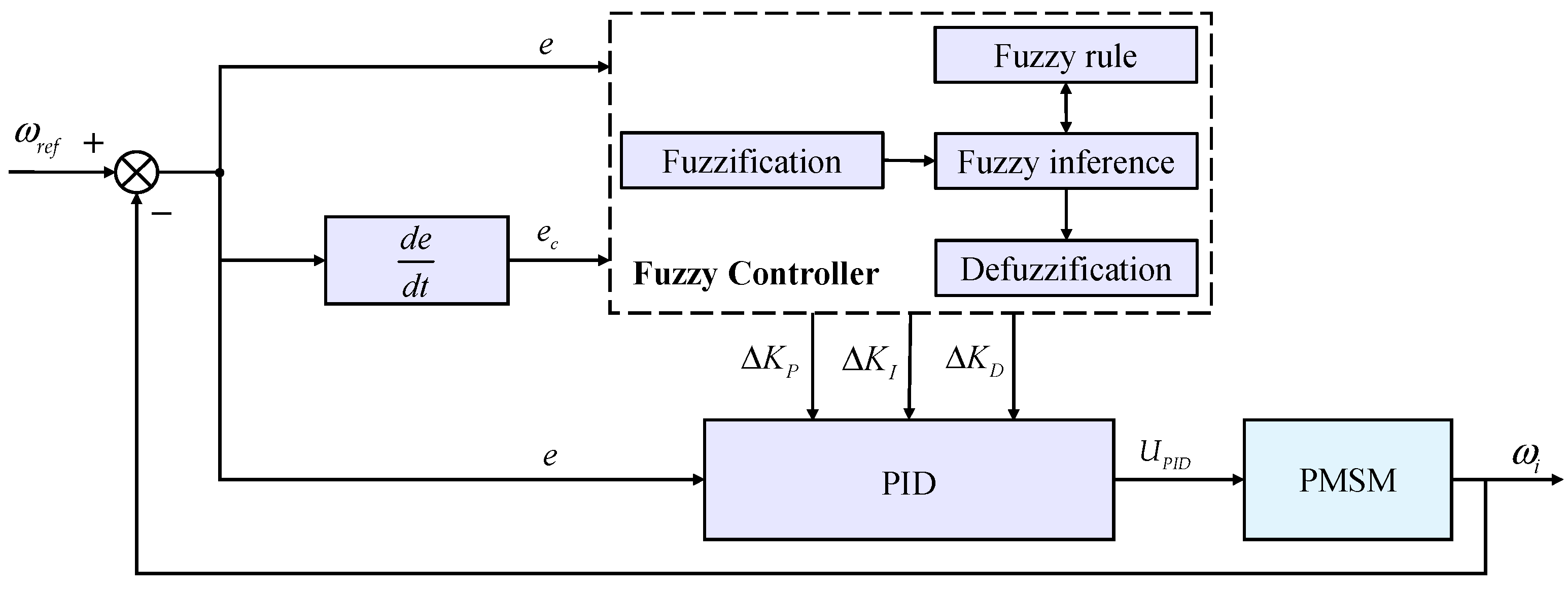
2.3. Controller Based on Fuzzy Control Algorithm

To uphold the comprehensive performance of multi-axis synchronization, beyond the adoption of an appropriate multi-axis synchronization control strategy, integration with suitable synchronization algorithms becomes imperative to ensure the precision of individual motor control. The controllers depicted in Figure 2 typically employ PID control algorithms. Nevertheless, conventional PID algorithms are limited to linear systems and may fail to accomplish dynamic regulation while exhibiting synchronization deficiencies. Among various algorithms, fuzzy control, devoid of reliance on exact mathematical models of the controlled entity, exhibits superior robustness and adaptability, rendering it highly suitable for deployment within the vector control system of permanent magnet synchronous motors (PMSMs). Consequently, this study amalgamates the fuzzy control algorithm with a conventional PID controller to formulate a fuzzy PID controller capable of autonomously adjusting parameters in response to external condition variations. This integration effectively enhances system stability and dynamic response performance.
The configuration of the fuzzy PID controller is illustrated in Figure 3. Initially, the system deviation e between the reference input and feedback, along with the rate of change ec of the deviation, are fed as inputs into the fuzzy controller, the appropriate quantization factors λe, λec, λP, λI, and fuzzy theory domain are selected for fuzzification. Subsequently, fuzzy rules are formulated, and the fuzzified quantity is determined utilizing the fuzzy inference table. Finally, the centroid method is employed for defuzzification, yielding an output of precisely Δ K P , Δ K I , and Δ K D to the PID controller. This process enables online adaptive adjustment of the PID parameters through the fuzzy controller [26].
The traditional PID control formula is as follows:
U P I D = K P ( e ( t ) + 1 T I 0 t e ( t ) d t + T D d e ( t ) d t ) = K P e ( t ) + K I e ( t ) + K D e ( t )
where e(t) represents the variance between the set speed and the actual speed, TI signifies the integral time constant, and TD represents the differential time constant.
Leveraging fuzzy control theory, the output of the fuzzy PID control depicted in Figure 3 is derived as follows:
U P I D = K P e ( t ) + K I e ( t ) + K D e ( t )
where K P = K P + Δ K P , K I = K I + Δ K I , and K D = K D + Δ K D correspond to the values of the PID controller parameters set by fuzzy control, respectively.

3. Simulation Experiment and Result Analysis

3.1. Model Construction

To evaluate the efficacy of the proposed improved synchronous control architecture, a six-axis motor synchronous control model is developed within the MATLAB/Simulink (R2021a) environment. The six AC permanent magnet synchronous motors (PMSMs) share identical parameters as delineated in Table 1. The simulation model, depicted in Figure 4, encompasses six single-axis control modules and synchronous compensator modules. Each single-axis control module comprises controllers and motors, as illustrated in Figure 5, where the PMSM adopts a vector control strategy with id = 0. Within the controller part, based on relevant studies [27,28,29] and combined with several simulation results, the parameters KP, KI, and KD are configured as 2.5, 0.3, and 0, respectively. The fuzzy theory domain of deviation e and the deviation rate of change ec are specified as [–10, 10], while the fuzzy theory domain of Δ K P and Δ K I are set to [–1, 1]. Furthermore, the quantization factors λe, λec, λP, and λI are established at 0.01, 0.0001, 7, and 3.5, respectively. In the synchronous compensator module, without synchronization control, deviation coupling control and improved deviation coupling control are separately implemented. The efficacy of these strategies is compared by real-time monitoring of speed variations across each axis.
The initial system speed is configured at 1000 rpm, with a simulation duration of 0.1 s and a sampling time of 0.00001 s utilizing fixed steps. Initially, all six motors commence operation under no load conditions. At 0.05 s, a load of 13 Nm is applied to motor 1 and 10 Nm to motor 2, while the remaining motors remain unloaded. By introducing loads to axes 1 and 2, motor 1 experiences multiple disturbances, thereby ensuring that the simulation conditions are in line with the actual situation and effectively demonstrates the efficacy of the synchronous control strategy.

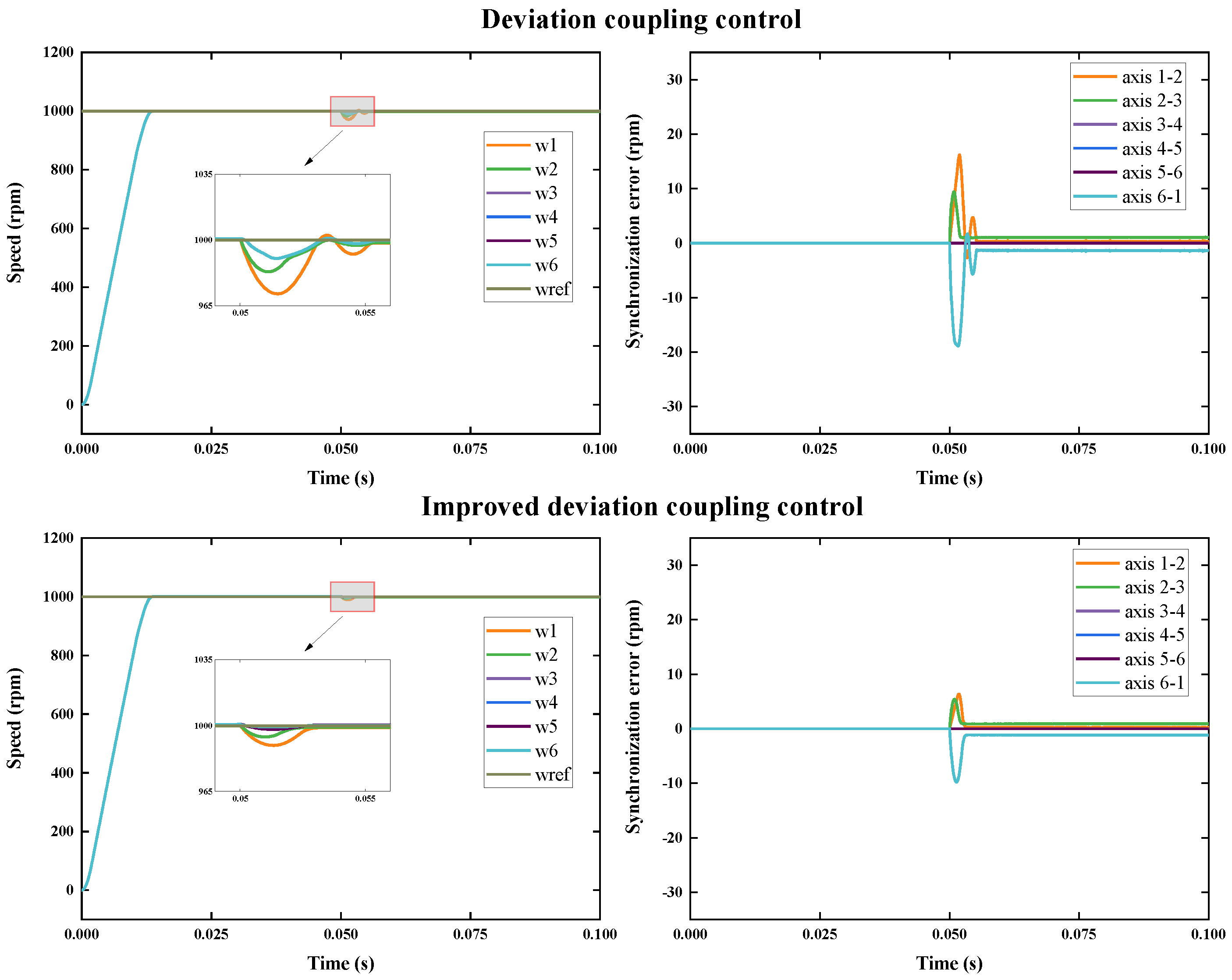
3.2. Analysis of Simulation Results

Utilizing the established simulation model, the synchronization of the method is confirmed by evaluating motor speeds, speed synchronization errors between adjacent axes, and the adjustment time for synchronization errors when various control strategies are implemented. The simulation outcomes employing the PID controller are depicted in Figure 6, while the results utilizing the fuzzy PID controller are illustrated in Figure 7.
Table 2 presents a comparative analysis of different control strategies under the PID controller. Notably, the improved deviation coupling control strategy exhibits superior synchronization efficacy. The maximum synchronization error decreases from 28.82 rpm to 11.71 rpm, marking a significant 59% reduction compared to the without synchronization control strategy. Additionally, the synchronization error adjustment time decreases from 5.94 ms to 4.74 ms, reflecting a 20% improvement. During the initial phase, the motor achieves a steady state at 0.02773 s due to speed overshoot oscillation. Upon the abrupt load application at 0.05 s, motors 1 and 2 manifest noticeable speed fluctuations. With the incorporation of the deviation coupling control strategy, motor speeds interact, leading to more pronounced speed fluctuations in the remaining motors and an increase in synchronization error adjustment time. However, the maximum synchronization error diminishes significantly. On the contrary, the improved deviation coupling control strategy better facilitates synchronous motion among multiple motors. Post sudden load application, minor speed fluctuations occur in motors 1 and 2 with the improved deviation coupling control strategy, while the impact on other motors remains minimal, resulting in almost negligible speed fluctuations. The speed adjustment time for each motor shortens, and the maximum synchronization error experiences a notable reduction. Compared to the deviation coupling control strategy, the maximum synchronization error decreases from 19.19 rpm to 11.71 rpm, marking a 39% improvement, while the synchronization adjustment time decreases from 8.92 ms to 4.74 ms, signifying a 49% enhancement.
Upon integrating fuzzy PID, depicted in Figure 7, it is evident that the phenomenon of speed overshoot oscillation during motor startup is notably mitigated. The motor achieves a steady state in a mere 0.01365 s, representing a remarkable 51% reduction in time. Additionally, under fuzzy PID control, the motor attains a steady state faster following a sudden load addition. Table 3 illustrates that compared to the deviation coupling control strategy, the improved deviation coupling control strategy can decrease the maximum synchronization error by 48%, from 18.88 rpm to 9.81 rpm, and reduce the synchronization error adjustment time by 32%, from 5.59 ms to 3.78 ms.
In summary, the improved deviation coupling control method incorporating fuzzy PID, as proposed in this study, exhibits distinct advantages in reducing synchronization error and enhancing dynamic adjustment performance. Compared to without synchronization control, the maximum synchronization error can be reduced by 66%, and the synchronization error adjustment time can be diminished by 37% after implementing the improved deviation coupling control method. This method significantly improves the synchronous performance of the multi-axis control system.

4. System Testing

In order to verify the effect of the multi-axis synchronous control method, a six-axis control platform is built for experimental testing. As shown in Figure 8, the experimental platform consists of a PC, a motion controller (self-developed in the laboratory, using ARM + FPGA architecture), six servo drives (Invt SV-DA200 series, Shenzhen INVT Electric Co., Ltd., Shenzhen, China), and six servo motors (Invt SV-ML06-0R4G-2-1A0, Shenzhen INVT Electric Co., Ltd., Shenzhen, China).
All six motors are commanded to run at 600 rpm. An oscilloscope (GDS-2202A, Good Will Instrument Co., Ltd., Suzhou, China) is used to observe the running status of the motors, recording the waveforms between each of two adjacent axes and measuring the time difference ΔT between the initial rising edges of two signals within a complete cycle, as well as the running cycle Ti of each motor. The experiment employs the EtherCAT bus for signal transmission between the motion controller and individual motors. Due to the distributed clock mechanism, the system-generated jitter is markedly below 1 µs, rendering transmission delays during time measurements negligible. The time difference ΔT between the two adjacent axes is used to reflect the system’s synchronization under different control methodologies. The actual motor speed can be calculated from the pulse period and pulse/revolution of the motor. The pulse period refers to the time required for the motor to generate a pulse, which is the period Ti measured by the oscilloscope. The pulses/revolutions represent the number of pulses required for each revolution of the motor. In this experiment, the motor employed has a pulse/revolution value of 2500 P/R, yielding the motor speed ni as follows:
n i = ( 60 × f ) / 2500 = 3 / ( 125 × T i )
where f is the motor frequency, which is inversely related to the period.
The measurement results of the waveforms after implementing different control algorithms are presented in Figure 9. It is evident that the improved deviation coupling control algorithm significantly reduces the time difference between each pair of adjacent axes, leading to a remarkable improvement in axis synchronization. When compared to the without synchronization control algorithm, as depicted in Figure 10a, the average time difference between axes is shortened from 9.23 ms to 5.42 ms, marking a 41% reduction. Moreover, it demonstrates a 12% improvement over the deviation coupling control algorithm. Furthermore, the speed variation between multiple axes is analyzed, as shown in Figure 10b. After incorporating the improved deviation coupling control algorithm based on fuzzy PID, the speed synchronization error between axes is greatly diminished. In comparison to the control algorithm without synchronization implementation, the average rotational speed synchronization error between axes is reduced by 33%, from 64.07 rpm to 42.37 rpm. Similarly, when compared to the deviation coupling control algorithm, it also achieves a 16% enhancement. Overall, the fuzzy PID improved deviation coupling control method optimizes the system’s synchronization performance, thereby improving the welding accuracy of the six-degrees-of-freedom robotic arm.

5. Conclusions

To enhance the synchronization performance of welding robotic arms and improve welding quality, this study presents an improved deviation coupling synchronization control method based on fuzzy PID. The improvement in the deviation coupling control strategy involves the design of an average speed compensator, effectively mitigating synchronization errors and reducing adjustment time in multi-axis control systems, thereby refining system synchronization. Furthermore, integrating the fuzzy PID algorithm into the controller promotes the adaptivity and stability of single-axis motors, leading to further suppression of synchronization errors and shorter adjustment times. Finally, without synchronization control, deviation coupling control and improved deviation coupling control are compared and analyzed. Simulation results reveal that, compared to without synchronization control, the improved deviation coupling control method reduces the maximum synchronization error of the system by 66% and decreases synchronization error adjustment time by 36%. Furthermore, compared to deviation coupling control, the improved method decreases the maximum synchronization error by 48% and reduces synchronization error adjustment time by 32%. Experimental findings demonstrate that embedding the improved deviation coupling control algorithm fosters cooperative motion among system axes and diminishes speed synchronization errors. These results comprehensively validate the effectiveness of the proposed method, offering a viable solution for the synchronization control of a six-degrees-of-freedom robotic arm with promising application prospects in the multi-axis synchronization control field.
In forthcoming research, an in-depth analysis will be conducted on positional synchronization subsequent to the implementation of a multi-axis synchronous control algorithm, targeting enhanced positioning accuracy of welding robotic arms. Furthermore, refinement of the deviation coupling synchronization control compensator is envisaged to cater to environments necessitating heightened welding precision.

Author Contributions

Conceptualization, Y.M., L.Q. and W.H.; methodology, Y.M.; software, Y.M.; validation, Y.M. and L.Q.; formal analysis, Y.M.; investigation, Y.M.; resources, L.Q.; data curation, Y.M. and M.S.; writing—original draft preparation, Y.M. and W.H.; writing—review and editing, Y.M., L.Q., W.H. and M.S.; visualization, Y.M.; supervision, L.Q. and W.H.; project administration, W.H.; funding acquisition, L.Q. All authors have read and agreed to the published version of the manuscript.

Funding

This research was funded by the National Key R&D Program of China (2022YFB3902500).

Institutional Review Board Statement

Not applicable.

Informed Consent Statement

Not applicable.

Data Availability Statement

The data presented in this study are available in article.

Conflicts of Interest

The authors declare no conflicts of interest.

References

  1. Licardo, J.T.; Domjan, M.; Orehovački, T. Intelligent Robotics—A Systematic Review of Emerging Technologies and Trends. Electronics 2024, 13, 542. [Google Scholar] [CrossRef]
  2. Wahidi, S.I.; Oterkus, S.; Oterkus, E. Robotic Welding Techniques in Marine Structures and Production Processes: A Systematic Literature Review. Mar. Struct. 2024, 95, 103608. [Google Scholar] [CrossRef]
  3. Tsuzuki, R. Development of Automation and Artificial Intelligence Technology for Welding and Inspection Process in Aircraft Industry. Weld. World 2022, 66, 105–116. [Google Scholar] [CrossRef]
  4. Guo, Q.; Yang, Z.; Xu, J.; Jiang, Y.; Wang, W.; Liu, Z.; Zhao, W.; Sun, Y. Progress, Challenges and Trends on Vision Sensing Technologies in Automatic/Intelligent Robotic Welding: State-of-the-Art Review. Robot. Comput.-Integr. Manuf. 2024, 89, 102767. [Google Scholar] [CrossRef]
  5. Wang, B.; Hu, S.J.; Sun, L.; Freiheit, T. Intelligent Welding System Technologies: State-of-the-Art Review and Perspectives. J. Manuf. Syst. 2020, 56, 373–391. [Google Scholar] [CrossRef]
  6. Niu, F.; Sun, K.; Huang, S.; Hu, Y.; Liang, D.; Fang, Y. A Review on Multimotor Synchronous Control Methods. IEEE Trans. Transp. Electrif. 2023, 9, 22–33. [Google Scholar] [CrossRef]
  7. Jerković Štil, V.; Varga, T.; Benšić, T.; Barukčić, M. A Survey of Fuzzy Algorithms Used in Multi-Motor Systems Control. Electronics 2020, 9, 1788. [Google Scholar] [CrossRef]
  8. Li, R.; Yuan, W.; Ding, X.; Xu, J.; Sun, Q.; Zhang, Y. Review of Research and Development of Hydraulic Synchronous Control System. Processes 2023, 11, 981. [Google Scholar] [CrossRef]
  9. Ismail, K.; Sabar, M. Speed Synchronization Technique for a Multi DC Motor System Using Serial Synchronization. In Proceedings of the 2020 International Conference on Sustainable Energy Engineering and Application (ICSEEA), Tangerang, Indonesia, 18–20 November 2020; pp. 1–5. [Google Scholar]
  10. Koren, Y. Cross-Coupled Biaxial Computer Control for Manufacturing Systems. J. Dyn. Syst. Meas. Control 1980, 102, 265–272. [Google Scholar] [CrossRef]
  11. Gao, L. Friction Compensation-Based Cross-Coupled Synchronous Control Method for Multiple Servo Motors. In Proceedings of the 2022 4th International Conference on Robotics, Intelligent Control and Artificial Intelligence, Dongguan, China, 16–18 December 2022; pp. 408–412. [Google Scholar]
  12. Payette, K. The Virtual Shaft Control Algorithm for Synchronized Motion Control. In Proceedings of the 1998 American Control Conference. ACC (IEEE Cat. No.98CH36207), Philadelphia, PA, USA, 26 June 1998; pp. 3008–3012. [Google Scholar]
  13. Han, G.; Hong, J.; Chen, B.; Zhu, H.; Zhu, B.; Yu, D. An Improved Virtual-Shaft Control Strategy for Speed Synchronization of Dual-SRM Drive. IEEE Trans. Ind. Electron. 2024, 71, 5485–5495. [Google Scholar] [CrossRef]
  14. Shih, Y.-T.; Chen, C.-S.; Lee, A.-C. A Novel Cross-Coupling Control Design for Bi-Axis Motion. Int. J. Mach. Tool. Manu. 2002, 42, 1539–1548. [Google Scholar] [CrossRef]
  15. Fang, P.; Wang, Y.; Zou, M.; Zhang, Z. Combined Control Strategy for Synchronization Control in Multi-Motor-Pendulum Vibration System. J. Vib. Control 2022, 28, 2254–2267. [Google Scholar] [CrossRef]
  16. Perez-Pinal, F.J.; Calderon, G.; Araujo-Vargas, I. Relative Coupling Strategy. In Proceedings of the IEEE International Electric Machines and Drives Conference, 2003. IEMDC’03., Madison, WI, USA, 1–4 June 2003; pp. 1162–1166. [Google Scholar]
  17. Chen, Q.; Dong, F.; Tao, L.; Nan, Y. Multiple Motors Synchronization Based on Active Disturbance Rejection Control with Improved Adjacent Coupling. In Proceedings of the 2016 35th Chinese Control Conference (CCC), Chengdu, China, 27–29 July 2016; pp. 4510–4516. [Google Scholar]
  18. Zhao, M.; Wang, Q.; Wang, Y.; Dong, Q. Multi-Motor Cooperative Control Strategy for Speed Synchronous Control of Construction Platform. Electronics 2022, 11, 4162. [Google Scholar] [CrossRef]
  19. Jiang, J.; Ren, J.; Gao, X.; Bian, H.; Wu, Y.; Lou, Z. Modeling and Simulation of Multi-Motor Synchronous Control System Based on Slide Mode Controller. In Proceedings of the International Conference on Smart Transportation and City Engineering (STCE 2022), Chongqing, China, 22 December 2022; p. 1246028. [Google Scholar]
  20. Lan, C.; Wang, H.; Deng, X.; Zhang, X.; Song, H. Multi-Motor Position Synchronization Control Method Based on Non-Singular Fast Terminal Sliding Mode Control. PLoS ONE 2023, 18, e0281721. [Google Scholar] [CrossRef]
  21. Zhang, P.; Li, Z. Multi-Motor Speed Synchronization Control System Based on Improved ADRC. In Proceedings of the 2023 8th International Conference on Intelligent Computing and Signal Processing (ICSP), Xi’an, China, 21–23 April 2023; pp. 542–546. [Google Scholar]
  22. Hao, Y.; Zhao, Y. Research on Coupling Control of Multiple Permanent Magnet Synchronous Motors Based on NAISMC and SMDO. PLoS ONE 2023, 18, e0292913. [Google Scholar] [CrossRef]
  23. Zou, S.; Zhao, W.; Wang, C. Tracking and Synchronization Control Strategy of Vehicle Dual-Motor Steer-by-Wire System via Super-Twisting SOSMC and MDCS. Mech. Syst. Signal Proc. 2023, 183, 109638. [Google Scholar] [CrossRef]
  24. Wu, X.; Wei, S.; You, J.; Sun, J. Research on Multi-Motor Speed Synchronous Control Based on Mean Coupling Control. In Proceedings of the 9th International Symposium on Sensors, Mechatronics, and Automation (ISSMAS 2023), Nanjing, China, 12 August 2023; p. 1298161. [Google Scholar]
  25. Li, L.; Sun, L.; Zhang, S. Mean Deviation Coupling Synchronous Control for Multiple Motors via Second-Order Adaptive Sliding Mode Control. ISA Trans. 2016, 62, 222–235. [Google Scholar] [CrossRef]
  26. Jin, F.; Wan, H.; Huang, Z.; Gu, M. PMSM Vector Control Based on Fuzzy PID Controller. In Proceedings of the Journal of Physics: Conference Series, 2nd International Conference on Electronic Engineering and Informatics, Lanzhou, China, 17–19 July 2020; p. 012016. [Google Scholar]
  27. Zhao, M.; Xu, X.; Yang, H.; Pan, Z. Design of a Predictive RBF Compensation Fuzzy PID Controller for 3D Laser Scanning System. Appl. Sci. 2020, 10, 4662. [Google Scholar] [CrossRef]
  28. Liu, C.; Zhao, J.; Gu, J.; Du, Y.; Li, Z.; Zhu, Z.; Mao, E. Pressure Control Algorithm Based on Adaptive Fuzzy PID with Compensation Correction for the Tractor Electronic Hydraulic Hitch. Appl. Sci. 2020, 10, 3179. [Google Scholar] [CrossRef]
  29. Deng, L.; Liu, T.; Jiang, P.; Xie, F.; Zhou, J.; Yang, W.; Qi, A. Design of an Adaptive Algorithm for Feeding Volume–Traveling Speed Coupling Systems of Rice Harvesters in Southern China. Appl. Sci. 2023, 13, 4876. [Google Scholar] [CrossRef]
Figure 3. Fuzzy PID controller structure.
Applsci 14 05300 g003
Figure 4. Six-axis motor synchronous control model.
Applsci 14 05300 g004
Figure 5. Single-axis control module.
Applsci 14 05300 g005
Figure 6. Simulation results of the six-axis synchronous control model with PID.
Applsci 14 05300 g006
Figure 7. Simulation results of the six-axis synchronous control model with fuzzy PID.
Applsci 14 05300 g007
Figure 8. Six-axis synchronous control experimental platform.
Applsci 14 05300 g008
Figure 9. Experimental waveforms of adjacent two axes with different methods. (a) Without synchronization control; (b) deviation coupling control; (c) improved deviation coupling control. In the figure, the red dotted line illustrates the time difference ΔT between two adjacent axes.
Applsci 14 05300 g009
Figure 10. Experimental results of six-axis synchronous control with different methods. (a) Time difference between two adjacent axes; (b) speed difference between two adjacent axes.
Applsci 14 05300 g010
Table 1. Motor parameters in the simulation.
ParametersValues
Rated torque T15 Nm
Rated speed v3000 rpm
Pole logarithm Pn4
Moment of inertia J0.003 kg·m2
Stator resistance R0.958 Ω
Magnetic chain amplitude ψf0.1827 Wb
Friction coefficient B0.003 N·m·s
Cross-axis inductance Ld0.00525 H
Straight-axis inductance Lq0.012 H
Table 2. Comparison of simulation data with PID.
Without Deviation CouplingImprovedCompare
Maximum synchronization error28.82 rpm19.19 rpm11.71 rpm−59%
Synchronization error adjustment time5.94 ms8.92 ms4.74 ms−20%
Table 3. Comparison of simulation data with fuzzy PID.
Deviation CouplingImprovedCompare
Maximum synchronization error18.88 rpm9.81 rpm−48%
Synchronization error adjustment time5.59 ms3.78 ms−32%
Disclaimer/Publisher’s Note: The statements, opinions and data contained in all publications are solely those of the individual author(s) and contributor(s) and not of MDPI and/or the editor(s). MDPI and/or the editor(s) disclaim responsibility for any injury to people or property resulting from any ideas, methods, instructions or products referred to in the content.

