Abstract
A shield tunnel is an assembly structure composed of connecting bolts and segments, generally considered to have good seismic performance. However, there is still a possibility of damage occurring in shield tunnels under strong seismic action. Therefore, a secondary lining can be applied on the inner side of the segment lining to improve the overall seismic performance of the shield tunnel. Using the Shiziyang Shield Tunnel as a case study, this paper employs numerical analysis to examine the seismic response characteristics of the shield tunnel with overlapped double-layer lining. Subsequently, it investigates the influence of segmental lining stiffness degradation and tunnel burial depth on the internal forces of the tunnel under seismic loads. The results indicate that under seismic loading, the stress in the segmental lining exceeds that in the secondary lining, with the maximum stress being three times higher. As the segmental lining stiffness decreases, the bending moment of the segmental lining decreases accordingly, while the secondary lining bending moment remains relatively constant. The bending moment of the segmental lining consistently surpasses that of the secondary lining. Furthermore, the variation in the axial force of the segmental lining is not significant, whereas the axial force in the secondary lining notably decreases. With increasing burial depth, the bending moment of the tunnel structure initially increases and then decreases. As the burial depth of the tunnel increases from 0.5D to 2D and 5.0D, the ratio of the maximum positive bending moment between the segmental lining and secondary lining first decreases and then increases, which are 7.56, 4.78, and 7.70, respectively. Similar patterns are also observed in axial forces. A burial depth of 2D is the critical depth between shallow and deep burial. When the tunnel is shallowly buried, the overlying strata have a significant impact on the seismic internal forces of the tunnel, which continue to increase with increasing burial depth. When the tunnel is deeply buried, it is subjected to the confining action of the strata, making it relatively safe, and the internal forces of the tunnel continue to decrease with increasing burial depth. Overall, under seismic loading, the segmental lining remains the primary load-bearing structure in a tunnel structure with double-layer lining.
1. Introduction
The seismic load-bearing capacity of shield tunnels is of great importance. Currently, the commonly used approach involves a single-layer lining, which consists of segments and connecting bolts to form an assembled structure. Pitilakis et al. [1] studied the seismic interaction behavior between above-ground structures and circular tunnels. Zou et al. [2] presented an efficient and reasonable methodology to evaluate the seismic fragility of shield tunnels based on a detailed investigation of the seismic performance of segments and joints in detail. Shen et al. [3] developed a two-dimensional saturated soil-structure dynamic interaction model for shield tunnel lining structures and investigated the interaction mechanism between the liquefiable soil layer and the tunnel. Zhang et al. [4] conducted a large-scale shaking table test and studied the seismic performance of shield tunnels under near-field ground motion. Wu et al. [5] proposed a refined lining model to simulate the mechanical behavior of segmental joints and investigated the seismic response of a shield tunnel passing saturated sand deposits with different relative densities. Sun et al. [6] studied the interaction of cross tunnels with different angles at close range during earthquakes, indicating that ground acceleration, internal force, and deformation of tunnel structure increase with the crossing angle between tunnels. Based on an undersea shield tunnel, Liu et al. [7] created and validated a series of refined models and investigated the development of crack and damage in shield tunnel lining under seismic loading. Wang et al. [8] carried out finite element simulation analyses of centrifuge shaking table tests to investigate the influence of segmental joints on seismic responses. Xu et al. [9] studied the dynamic response characteristics of the bottom soil layer of a shield tunnel with different structural stiffness under different seismic loads, using the finite difference method. Zhao et al. [10] investigated the damage pattern of the concrete lining in a large-diameter subsea shield tunnel under different seismic loading intensities.
A shield tunnel with single-layer lining possesses good seismic performance. However, there remains a risk of damage under conditions of high-intensity or adverse geological conditions. In order to enhance the seismic performance of shield tunnels, secondary linings are applied to the inner side of the tunnel. Based on the existing numerical models of the shield tunnel with double-layer lining, Yan et al. [11] developed an improved numerical model and verified it with a similar model test. Yang et al. [12] established a three-dimensional finite element model to analyze the stress distribution and deformation characteristics of the prestressed composite lining when the tunnel is under the completed segment assembly condition. Using a similarity model test and the engineering background of the Shiziyang Tunnel, Wang et al. [13] studied the influence of the joint surface type on the mechanical behaviors and failure characteristics of the lining structure. Taking the Shiziyang shield tunnel as a case study, Wang et al. [14] investigated the interaction between shield segmental lining and secondary lining under different construction times, using similar model tests. Based on the model tests, Guo et al. [15] pointed out that under the high internal water pressure, structure fractures appeared first at the hance of the secondary lining, then at the vault and the arch bottom. Other scholars have also investigated the static load-bearing capacity of the shield tunnel with double-layer lining [16,17,18,19,20,21,22].
Building upon these understandings, scholars have further studied the seismic response characteristics of the shield tunnel with double-layer lining. Xin et al. [23] explored polypropylene fiber-reinforced concrete as a secondary lining to reduce the seismic response intensity of tunnel structures. Zhou et al. [24] investigated the seismic performance of single-layer linings, double-layer linings, and isolation layers under different combinations of loading conditions. Based on shake table tests, Zhang et al. [25] studied the influence of secondary lining configurations on the seismic response of tunnels, including a tunnel only with segmental linings, a tunnel with additional semi-ring secondary lining, and a tunnel with additional full-ring secondary lining. The aforementioned studies have mostly focused on the tunnel structure itself, with insufficient analysis of the relevant structural parameters that affect its seismic response.
In conclusion, current research on the seismic response of shield tunnels predominantly focuses on single-layer linings. However, there are few studies on the seismic response of shield tunnels with secondary linings. Moreover, there is a lack of analysis on the structural characteristics of the parameters related to the shield tunnels with secondary linings. Therefore, this paper aims to investigate the seismic response characteristics of shield tunnels with overlapped double-layer linings and analyze the influence of segmental lining stiffness and burial depth on the seismic response of shield tunnels. The conclusions drawn from this study can provide valuable references for relevant engineering projects.
2. Engineering Background
The Shiziyang Tunnel is a pivotal project of the Guangzhou-Shenzhen-Hong Kong High-Speed Railway. It passes under the main navigation channel of the Pearl River—the Shiziyang Waterway. The tunnel project has a total length of 10.8 km, with a shield tunneling section spanning 9340 m. It is the first underwater railway shield tunnel in China.
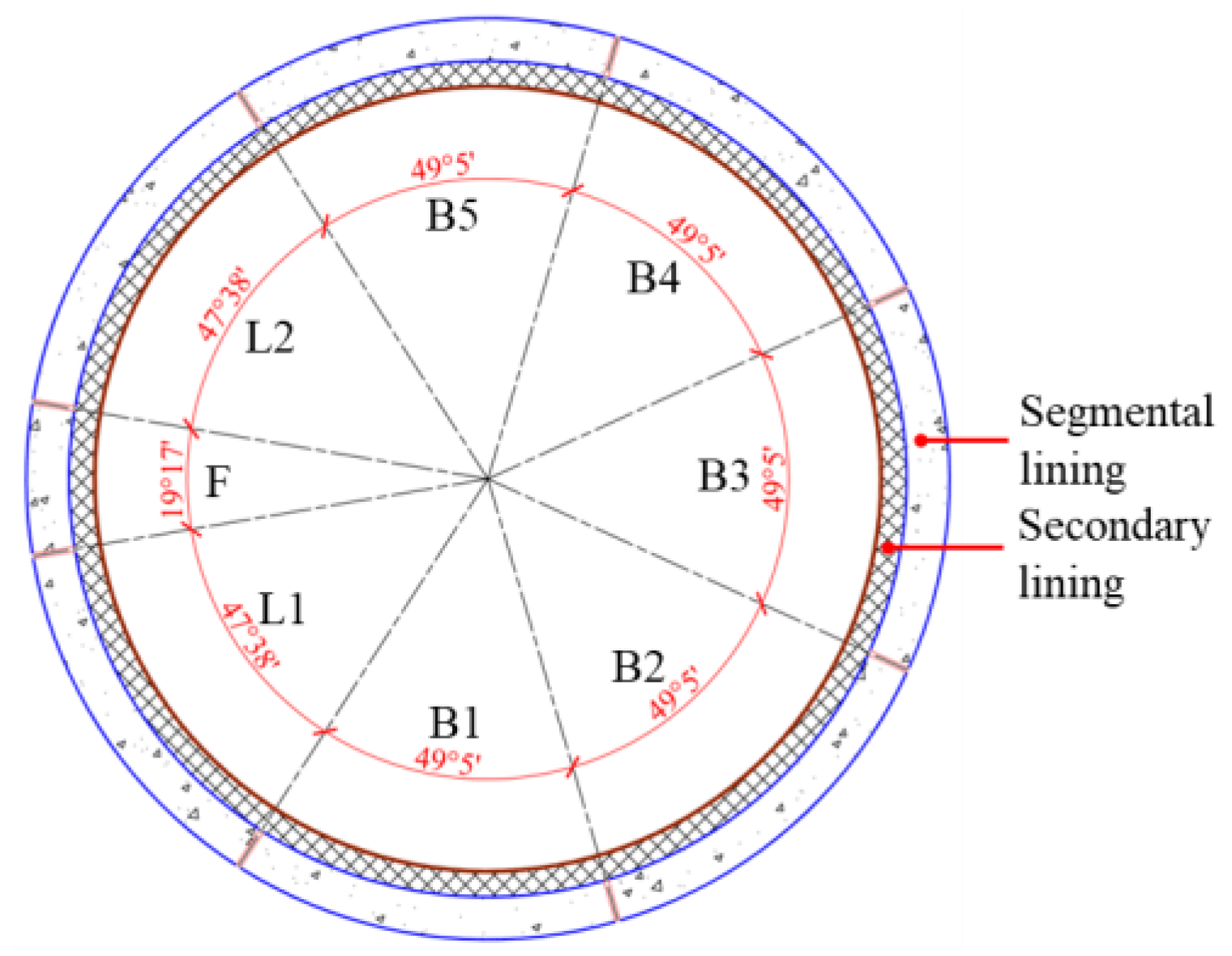
In the Shiziyang Shield Tunnel, which passes through weak and uneven geological formations at the entrance and exit sections, a double-layer lining structure is adopted due to structural safety concerns (Figure 1). The outer diameter of the shield tunnel is 10.80 m, with a thickness of 0.50 m for the segmental lining. The width of the segmental lining is 2 m. The diameter of the secondary lining is 9.80 m, with a thickness of 0.30 m. There are eight segments in each segmental ring, with 24 bolts connecting them. There are 22 M30 circumferential bolts arranged between two interacting rings (Manufactured by CHINA RAILWAY 12TH BUREAU GROUP CO., LTD., located in Taiyuan, China). The concrete strength grade for the segmental lining is C50, while the concrete strength grade for the secondary lining is C25.
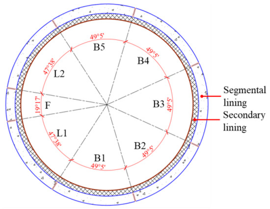
Figure 1.
The schematic diagram of the segmental ring.
3. Finite Element Model of Shield Tunnel
In general, double-layer linings can be classified as composite linings and overlapped linings, with the difference lying in whether the transfer of shearing force between the linings is considered. For composite linings, the grooves on the inner surface of the segmental lining are completely filled and smoothed with cement before applying the secondary lining. It can be assumed that only normal force is transferred between the segmental lining and the secondary lining. For overlapped linings, the large grooves on the inner side of the segments are filled and smoothed with concrete, while other areas of the segmental lining are roughened before applying the secondary lining. This results in a closer interaction between the segmental lining and the secondary lining, allowing for the transfer of compressive and some shearing force. This study focuses on the shield tunnel with overlapped linings, establishing numerical analysis models to clarify its seismic response characteristics.
3.1. The Numerical Model
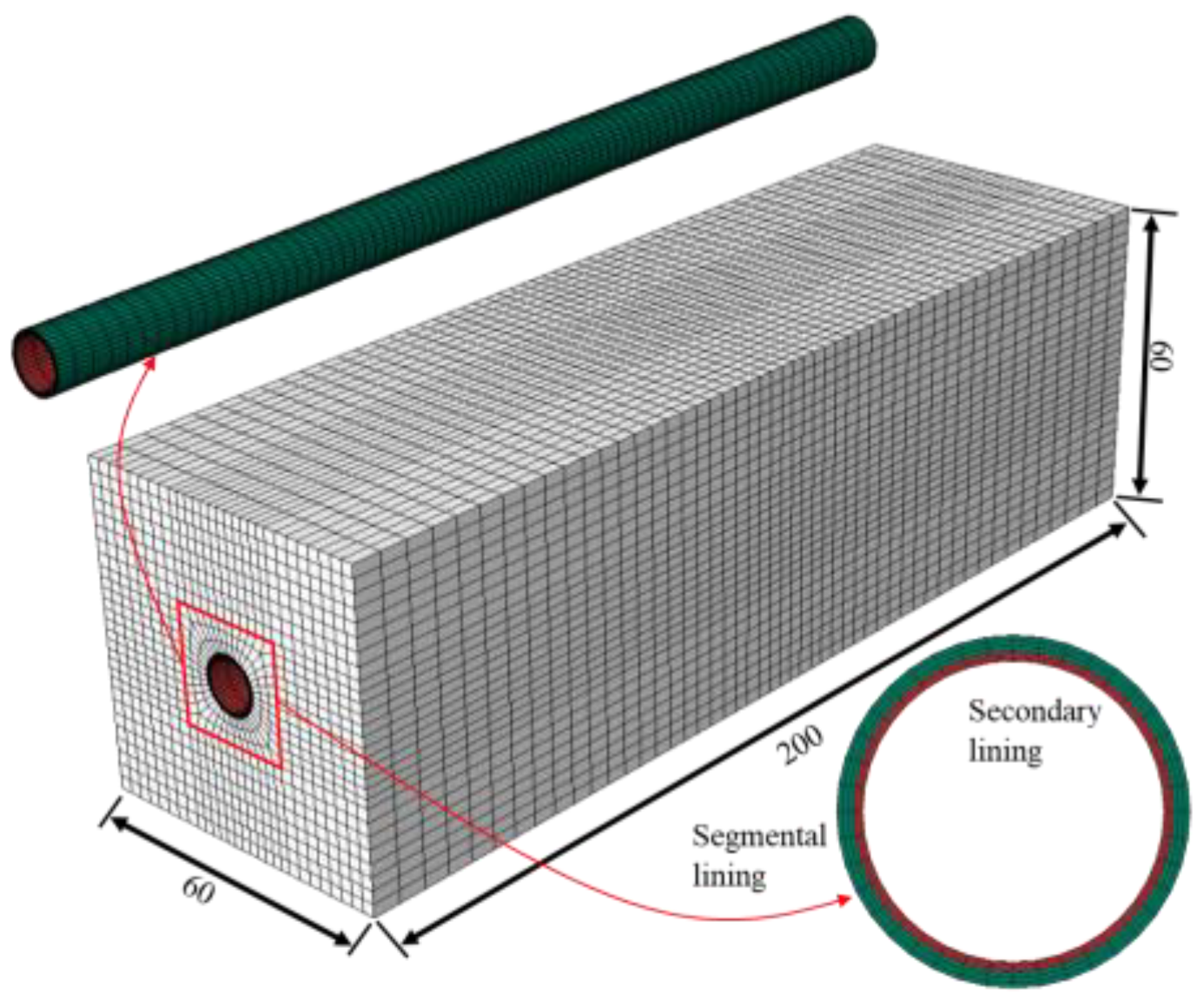
A three-dimensional finite element analysis model is established using Abaqus 2020 software. The dimensions of the model are length × width × height = 60 m × 60 m × 200 m, with the burial depth of the shield tunnel being 25 m. The segmental lining is modeled using an equivalent homogeneous circular ring model, which considers the weakening effect of the segmental joints on the lateral stiffness of the segmental rings by using a reduction factor of 0.8 [26]. A secondary lining is applied on the inner side of the segmental lining (Figure 2). Both the stratum and the shield tunnel adopt 3D stress-reduced integration elements (Semens, Plano, TX, USA).
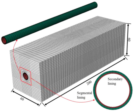
Figure 2.
Double-layer lining shield tunnel numerical model (Unit: m).
The geological parameters of the numerical model are selected according to the “Design Specification for the Shiziyang Tunnel of the Guangzhou-Shenzhen-Hong Kong Passenger Dedicated Line” [27]. The segmental lining and secondary lining are modeled with concrete under a linear elastic constitutive model, with material parameters shown in Table 1.

Table 1.
Material parameters.
This model represents an overlapped double-layer lining structure, where both axial force and shear force can be transferred between the segmental ring and the secondary lining. Normal contact is adopted between the segmental lining and the secondary lining, while tangential contact utilizes frictional contact with a friction coefficient of 0.6 [13,28].
3.2. Input Seismic Motion and Dynamic Boundary
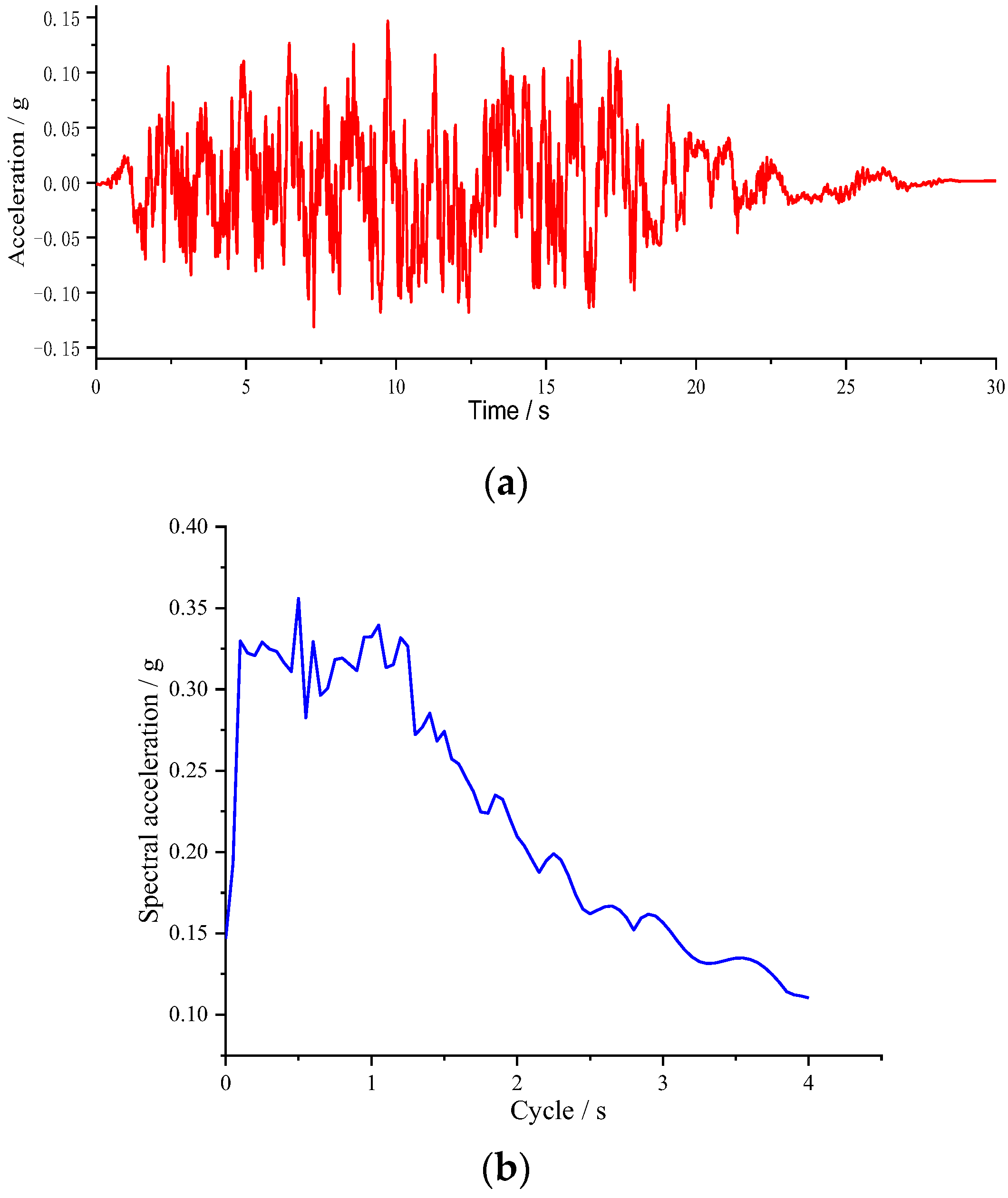
The Shiziyang Tunnel is designed to withstand seismic forces calculated based on earthquake ground motion parameters at a 2% exceedance probability level over a 100-year return period. Scholars investigated the seismic response of a subway metro station and tunnel through a large set of numerical simulations using different real and artificial accelerograms and found that the structural seismic response may be significantly influenced by the main characteristics of the accelerogram considered [29]. Due to the lack of locally measured earthquake motion, according to the “Design Specification for the Shiziyang Tunnel of the Guangzhou-Shenzhen-Hong Kong Passenger Dedicated Line” [27], an artificially synthesized motion with a peak acceleration of 0.15 g was chosen as the seismic load, applied laterally along the tunnel, with a duration of 30 s (Figure 3).

Figure 3.
Input seismic motion: (a) Acceleration time–history; (b) Response spectrum.
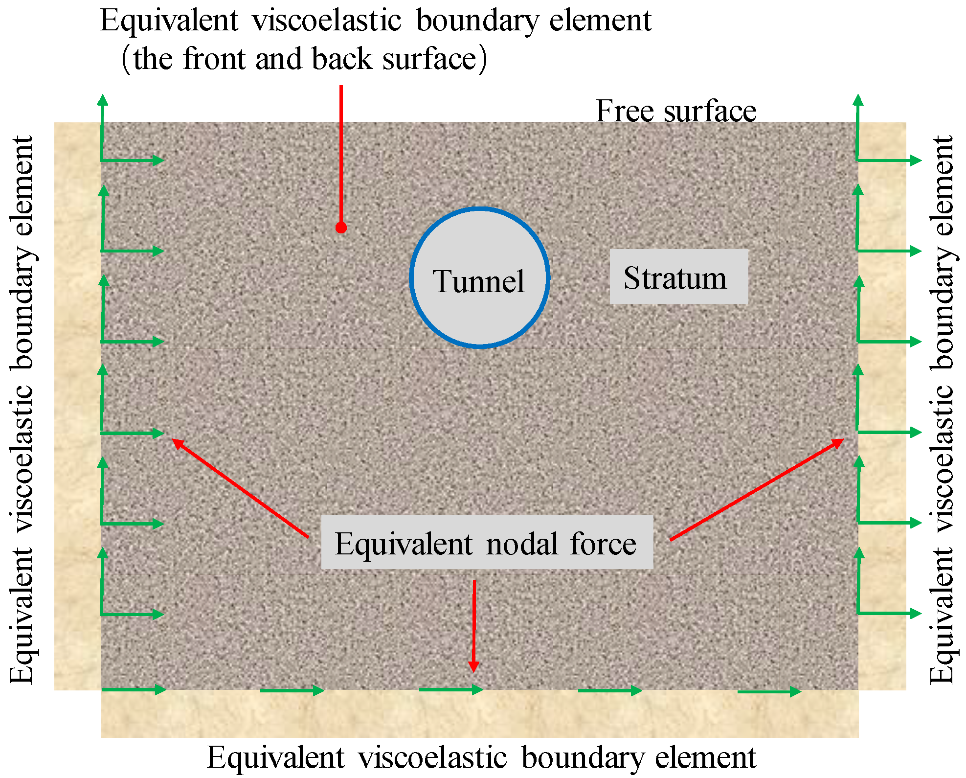
To reduce the reflection of seismic waves at the truncated boundaries of the model, equivalent viscoelastic artificial boundary elements are applied to the side and bottom boundaries. The seismic loads are converted into forces applied to the boundary nodes, enabling the study of the seismic response characteristics of the shield tunnel (Figure 4).
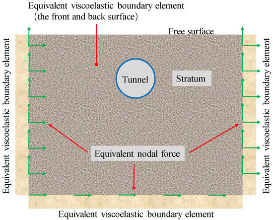
Figure 4.
Equivalent viscoelastic boundary element artificial dynamic boundary.
Except for the surface being free, equivalent viscoelastic boundary elements are set up in both the normal and bottom directions of the model. The application method of equivalent viscoelastic boundary elements is to extend a layer element outward from the boundary elements of the finite element model. The parameter calculation formulas for the equivalent viscoelastic boundary element are
Here,
—Equivalent shear modulus of artificial boundary elements;
—Medium shear modulus;
—Distance from wave source to artificial boundary point;
—Tangential spring stiffness;
—Normal spring stiffness;
—Equivalent elastic modulus of artificial boundary elements;
—Artificial boundary element thickness;
—Equivalent Poisson’s ratio of strata;
—Equivalent damping coefficient of artificial boundary element material;
—Medium mass density;
—S-wave velocity;
—P-wave velocity.
A reasonable seismic load application method needs to be matched with a dynamic boundary. Here, the seismic load is transformed into equivalent nodal forces and applied to the boundary points of the model. The equivalent nodal forces are calculated as follows:
Tangential force at the bottom boundary
Normal and tangential forces at the left boundary
Normal and tangential forces at the right boundary
Tangential force at the front boundary
Tangential force at the back boundary
Here, .
Here,
—Equivalent nodal force on boundary nodes, with superscripts indicating the direction of the outer normal of the boundary interface. When consistent with the coordinate axis, it is positive, and the subscript represents the direction of the equivalent force on the node;
—The normal (tangential) stiffness of the artificial boundary element;
—Damping coefficient of artificial boundary element;
—First Lame constant;
—Model height;
—The distance from the node to the bottom boundary;
—Time of the input S-wave at the node;
—Time of S-wave reflection from the surface before reaching the node.
4. Result Analysis
4.1. Structural Acceleration
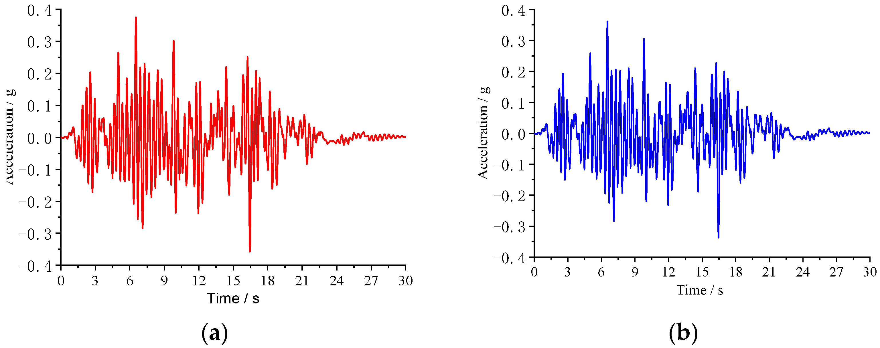
Taking the acceleration at the crown as an example, here analyzes the acceleration response characteristics of the shield tunnel with double-layer lining (Figure 5).
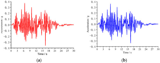
Figure 5.
Acceleration time–history curve: (a) Segmental lining; (b) Secondary lining.
From Figure 4, it can be observed that the seismic acceleration curve shapes of the segmental rings and secondary lining are largely consistent, indicating good transfer of internal forces between layers. The initial seismic response of the tunnel structure is relatively small, with both the segmental lining and secondary lining reaching peak acceleration at approximately 6.4 s. The maximum acceleration on the segmental lining is 0.37 g, which exceeds the maximum acceleration of 0.36 g on the secondary lining. This indicates that the segmental lining directly experiences forced displacement transmitted from the stratum, resulting in a more pronounced seismic response.
By extracting the maximum accelerations of the tunnel structure and the stratum at the same height, the seismic acceleration amplification factor can be obtained (Figure 6).
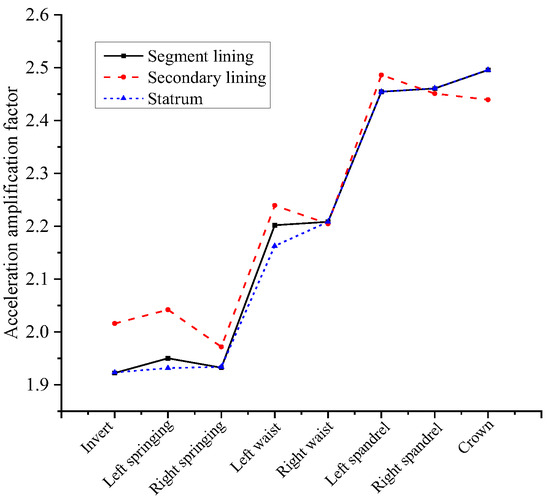
Figure 6.
Acceleration amplification factor.
From the above figure, it is evident that at the invert, the acceleration amplification factor of the segmental lining and stratum is relatively small, around 1.9, while that of the secondary lining is approximately 2.02. As the burial depth decreases, the acceleration amplification factor in the structure and the stratum gradually increases. At the crown, the acceleration amplification factor of the segmental lining, secondary lining, and stratum are more consistent, with a value of approximately 2.45. The acceleration amplification law on the segmental lining is generally consistent with that of the surrounding stratum due to the constraining effect of the stratum on the segmental lining, resulting in seismic responses consistent with the adjacent stratum. However, the acceleration amplification factor on the secondary lining is generally greater than that on the segmental lining. This is because the secondary lining has one side facing the tunnel clearance, experiencing less constraint, thus exhibiting a more pronounced acceleration response.
In conclusion, there is a certain degree of fluctuation in the acceleration amplification effect between the tunnel structure and stratum, but overall, the acceleration amplification factors of the tunnel structure gradually increase from the invert to the crown. Due to the strong interaction between the stratum and the segmental lining, the acceleration amplification factors of these two at the same location are generally consistent.
4.2. Structural Stress
Extract the maximum stresses of the tunnel structure as shown in (Figure 7).
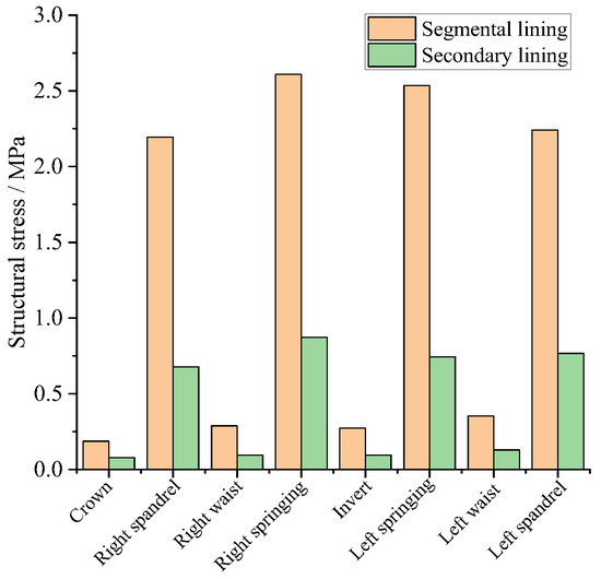
Figure 7.
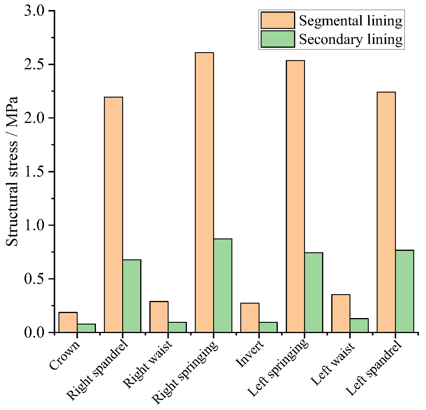
Structural stress.
From the figure, it can be observed that both the segmental lining and the secondary lining experience significant stresses under seismic loads, with higher stresses at the springing and spandrel. For the segmental lining, the stresses at the right spandrel, right springing, left spandrel, and left springing are 2.19 MPa, 2.61 MPa, 2.24 MPa, and 2.54 MPa, respectively. For the secondary lining, the stresses at the right spandrel, right springing, left spandrel, and left springing are 0.68 MPa, 0.87 MPa, 0.77 MPa, and 0.74 MPa, respectively. It is evident that both the segmental lining and the secondary lining exhibit relatively high stresses at their corresponding locations. This indicates that in the shield tunnel with overlapped double-layer lining, the load-transferring between the segmental lining and the secondary lining is effective, allowing them to collectively withstand seismic loads as a cohesive structure.
In terms of stress distribution, the stresses at all the positions of the segmental lining are greater than those at the corresponding positions of the secondary lining. The peak stress of the tunnel structure occurs in the right springing area, where the stress in the segmental lining is 2.61 MPa, approximately three times larger than that of the secondary lining. Thus, it can be inferred that under seismic loads, the segmental lining serves as the primary load-bearing structure, while the secondary lining acts as a reinforcing structure and shares a portion of the seismic load.
4.3. Structural Deformation
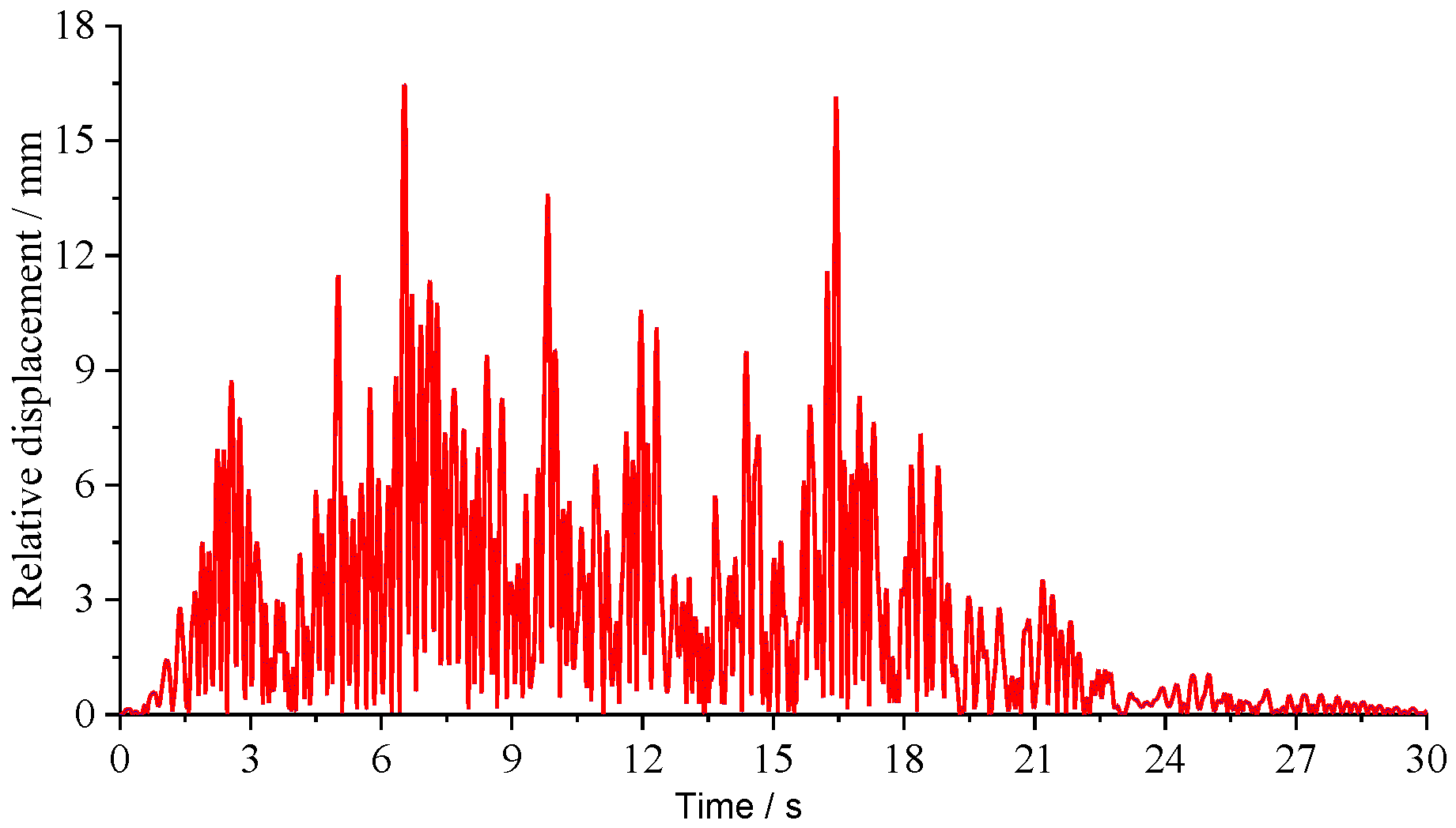
The time–history curves of relative displacements between the tunnel crown and invert are shown in Figure 8.

Figure 8.
Time–history curve of relative displacement between tunnel crown and invert.
Under the initial seismic loading, the relative displacements between the tunnel crown and invert are relatively small. As the input seismic acceleration increases, the relative displacements of the tunnel structure rapidly escalate, reaching a peak value of approximately 16.46 mm at 6.5 s. In the later stages of seismic loading, the relative displacements of the lining structure gradually decrease, indicating a weaker vibrational response compared to the initial stage. Additionally, at 6.5 s, the maximum inclination angle of the tunnel structure is approximately 0.00152 rad, which is within the permissible limit of 1/350, indicating that the tunnel structure is in a safe condition.
5. Influence of Calculation Parameters on Dynamic Response of Double-Layer Lining Shield Tunnel
The design parameters of the tunnel structure significantly affect its seismic performance. Since the Shiziyang Tunnel is an underwater tunnel, the mechanical properties of the segmental lining may degrade due to the combined effects of high water pressure and chemical erosion. This degradation could affect the seismic response characteristics of the overall tunnel structure, which includes the segmental lining and secondary lining. This chapter investigates the influence of variations in segmental lining stiffness and burial depth on the seismic response of the shield tunnel with double-layer lining.
5.1. Segmental Lining Stiffness Degradation
The elastic modulus of the segmental lining is reduced to 90%, 80%, 70%, and 60% of the ordinary value (i.e., 100% segment stiffness in the following figures) to simulate the stiffness degradation.
5.1.1. Structural Bending Moment
Under the condition of segmental lining stiffness degradation, the bending moments of the shield tunnel under the seismic motion (depicted in Figure 3) are illustrated in Figure 9 and Figure 10.
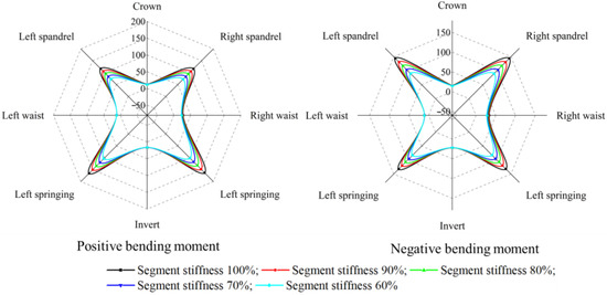
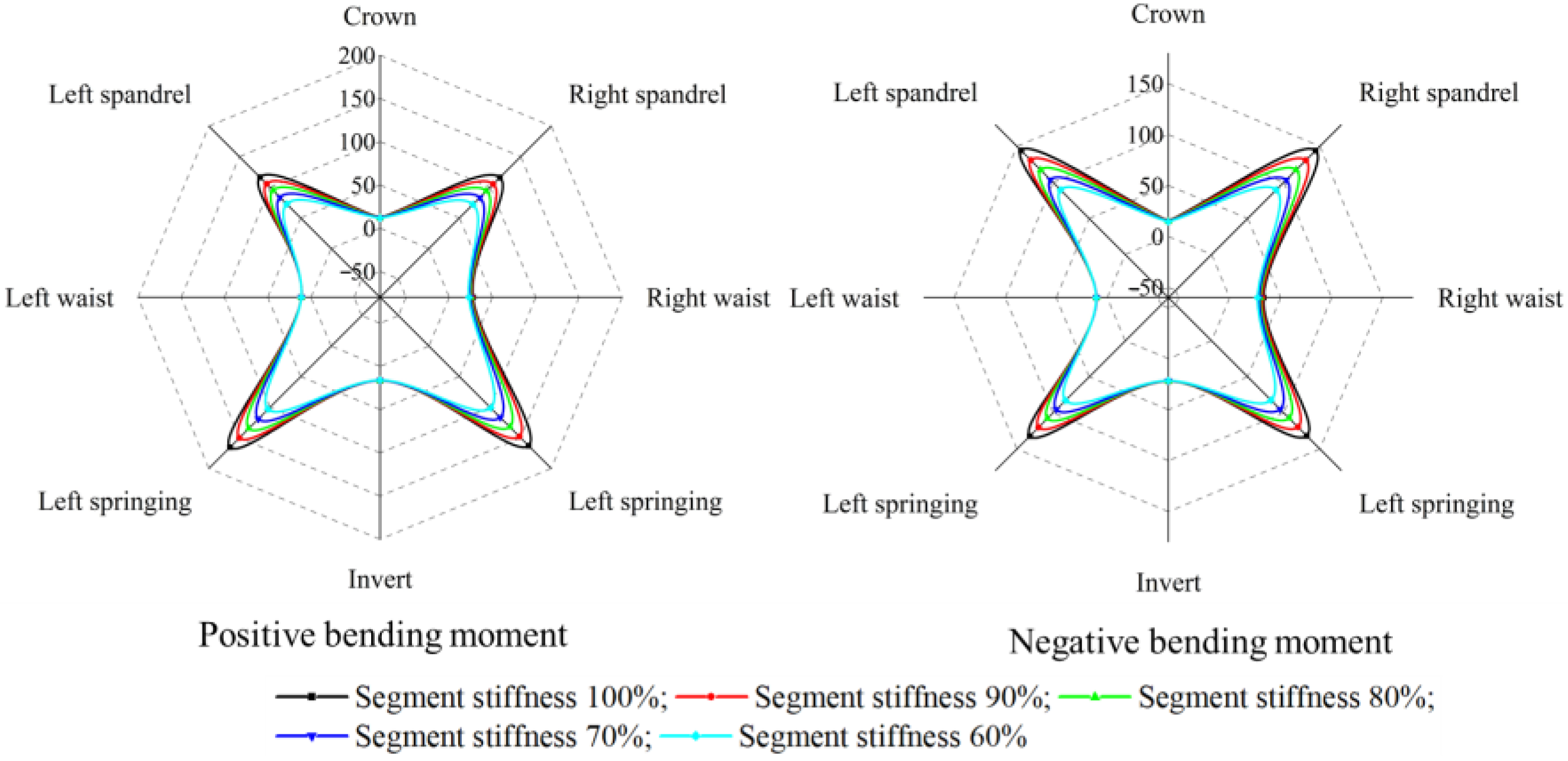
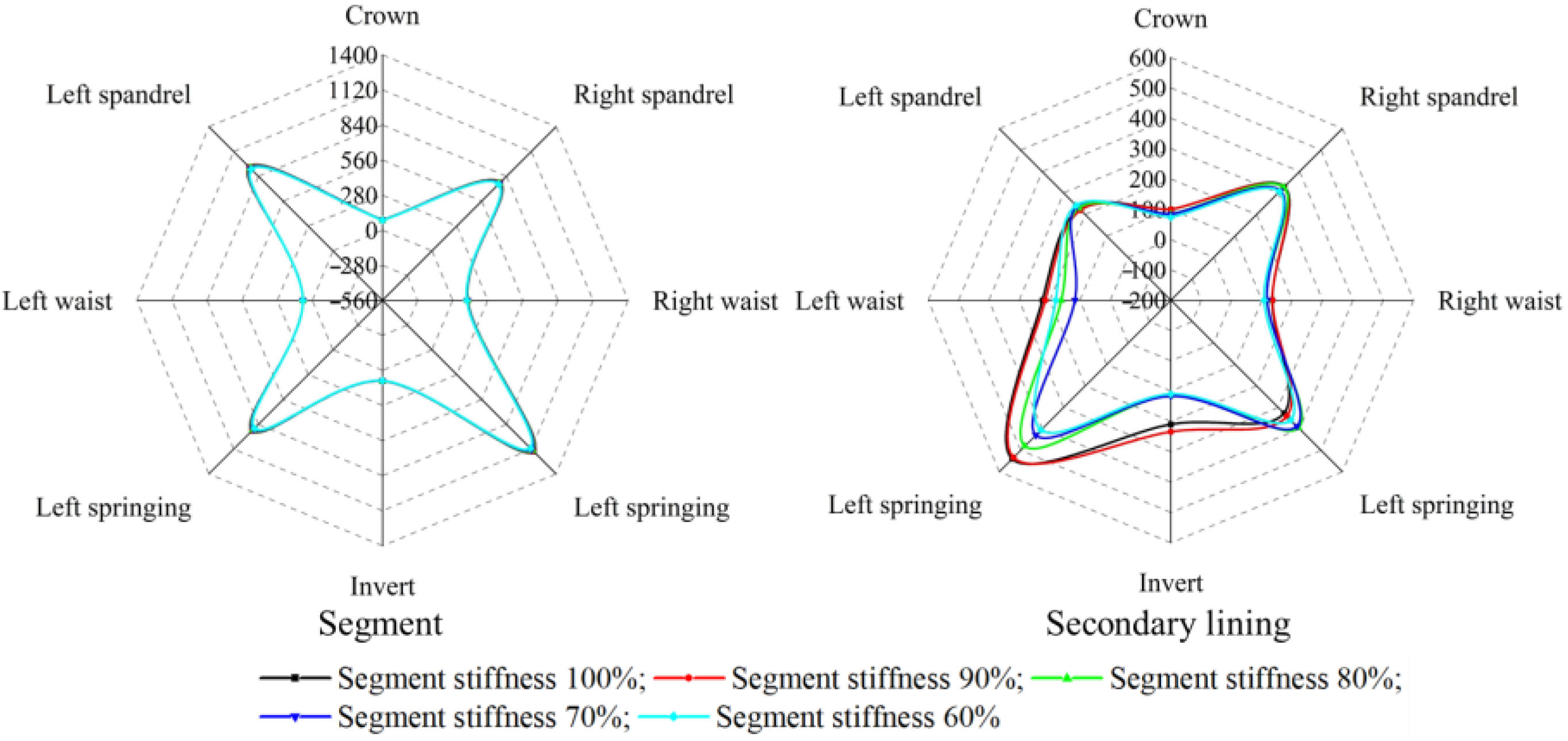
Figure 9.
Maximum bending moments of segment (Different segment stiffness. Unit: kN·m).
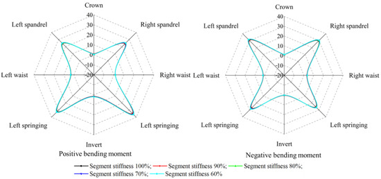
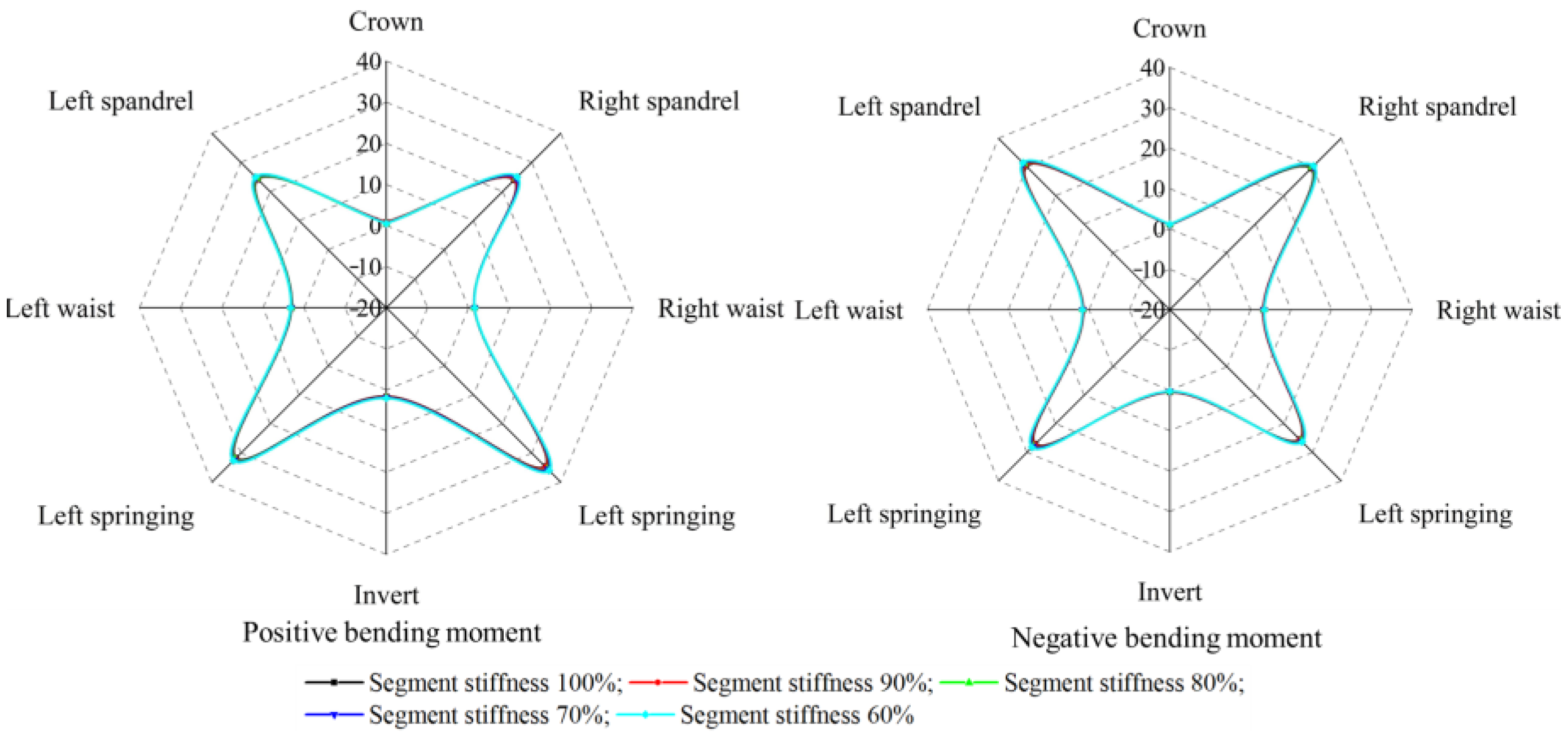
Figure 10.
Maximum bending moments of secondary lining (Different segment stiffness. Unit: kN·m).
From these figures, it can be observed that the distribution characteristics of bending moments in both the segmental lining and the secondary lining remain unchanged regardless of the stiffness degradation. The maximum bending moments in the segmental lining and the secondary lining of all cases consistently occur in the conjugate 45° region. Specifically, the maximum positive bending moment occurs in the springing, while the maximum negative bending moment occurs in the spandrel.
The maximum bending moments for the tunnel structure are shown in Figure 11.
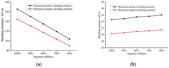
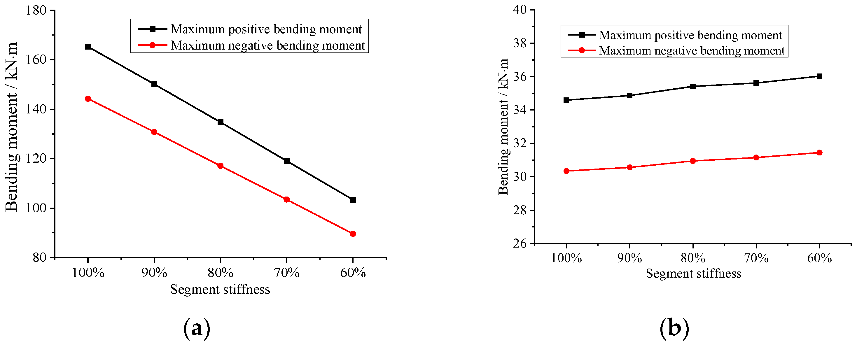
Figure 11.
Variation curve of the maximum bending moment under segment stiffness degradation: (a) Segmental lining; (b) Secondary lining.
Figure 11 shows that as the segmental lining stiffness degrades from 100% to 60%, the maximum positive bending moment of the segmental lining gradually decreases from 165.31 kN·m to 103.38 kN·m, while the maximum negative bending moment decreases from 144.27 kN·m to 89.61 kN·m, approximately in a linear manner. The maximum positive bending moment remains greater than the maximum negative bending moment. The changes in the maximum positive and negative bending moments of the segmental lining are relatively consistent, with the decreasing rate of the maximum positive bending moment being approximately 1.13 times higher than that of the maximum negative bending moment.
For the secondary lining, when the segmental lining stiffness decreases from 100% to 60%, the maximum positive bending moment remains around 35 kN·m, while the maximum negative bending moment remains around 31 kN·m.
As the stiffness of the segmental lining degrades, the bending moment of the segmental lining gradually decreases, while the bending moment of the secondary lining remains almost unchanged. Numerically, although the stiffness of the segmental lining decreases, it remains greater than that of the secondary lining. This indicates that when the segmental lining stiffness degrades, the segmental lining remains to be the primary load-bearing structure, while the bending moment of the secondary lining is hardly affected.
As the stiffness of the segmental lining degrades, the ratio of the maximum bending moment between the segmental lining and the secondary lining gradually decreases. When the segmental lining stiffness decreases from 100% to 60%, the ratios of the maximum positive bending moment decrease from 4.77 to 2.86, a decrease of 40.04%. Similarly, the ratios of the maximum negative bending moment decrease from 4.75 to 2.84, a decrease of 40.02%. This indicates a significant change in the load distribution of the tunnel structure under seismic loads.
5.1.2. Structural Axial Force
The axial forces of the segmental lining and secondary lining under segmental lining stiffness degradation are extracted and shown in Figure 12.
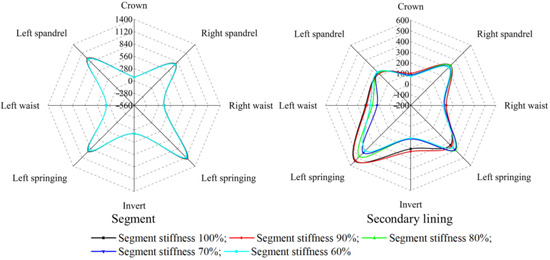
Figure 12.
Maximum axial force of tunnel structure (Different segment stiffness. Unit: kN).
As observed from Figure 11, the degradation of segmental lining stiffness does not alter the overall distribution pattern of axial forces in the tunnel structure. That is, the axial force is significant in the invert and spandrel areas, while it is relatively smaller in other regions.
The maximum axial forces in the tunnel structure are illustrated in Figure 13.

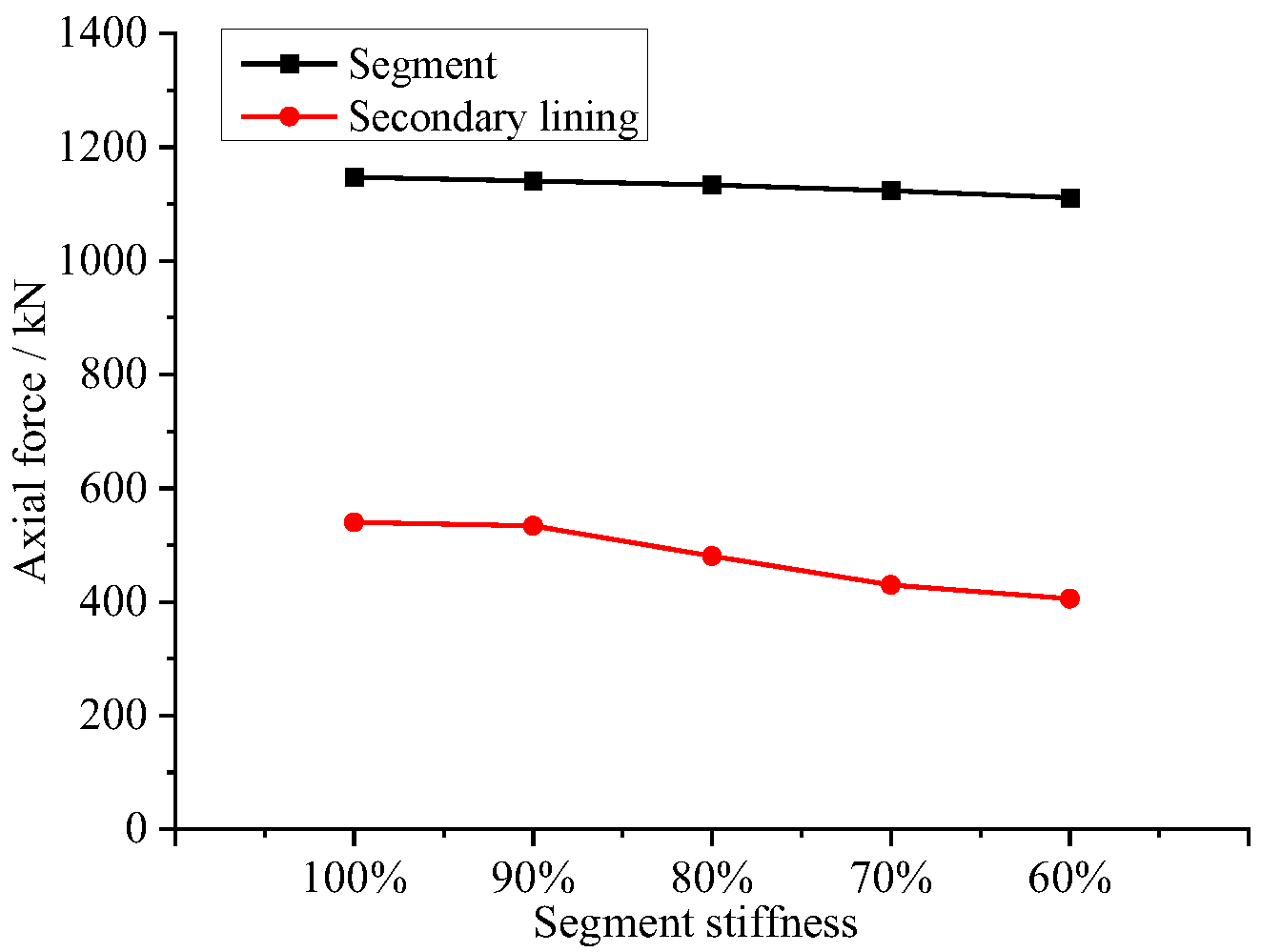
Figure 13.
Variation curve of the maximum axial force under segment stiffness degradation.
The maximum axial force is observed at the right springing of the segmental lining, and it does not change significantly with the degradation in segmental lining stiffness. When the segmental lining stiffness degrades from 100% to 60%, the axial force at the right springing changes from 1147.33 kN to 1111.06 kN.
The maximum axial force of the secondary lining is observed at the left springing and decreases significantly with the degradation in segmental lining stiffness. When the segmental lining stiffness degrades from 100% to 60%, the axial force at the left springing decreases from 540.17 kN to 405.61 kN, a decrease of 24.9%.
In conclusion, under the segmental lining stiffness degradation, the segmental lining and the secondary lining exhibit uncoordinated deformation under seismic loads, resulting in asynchronous changes in axial force. Specifically, in regions where axial force is relatively high, there is a significant reduction in axial force; conversely, in regions where axial force is relatively low, the changes in axial forces are not significant. Under the same conditions, the axial force in the segmental lining is significantly higher than that in the secondary lining, indicating that the segmental lining remains the primary load-bearing structure.
5.2. Tunnel Burial Depth
Burial depth is a critical construction parameter for tunnels. In this study, six scenarios with burial depths of 0.5D, 1D, 1.5D, 2.0D, 3.0D, and 5.0D (D refers to the outer diameter of the shield tunnel, which is 10.80 m in this research) are selected to investigate the seismic response characteristics of the shield tunnel with double-layer lining.
5.2.1. Structural Bending Moment
The maximum bending moments of the segmental lining and secondary lining at different burial depths are illustrated in Figure 14 and Figure 15, respectively
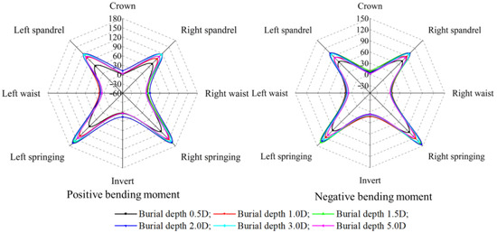
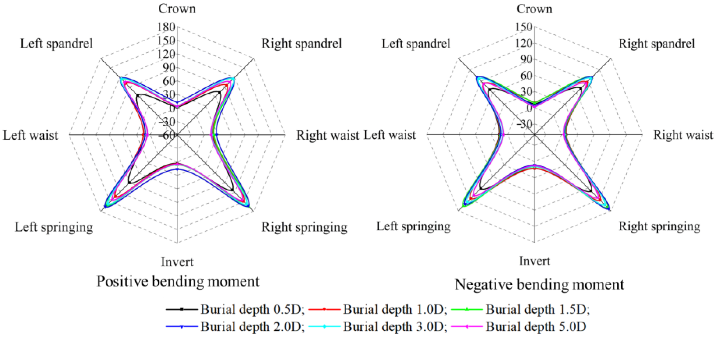
Figure 14.
Maximum bending moment of segment (Different burial depths. Unit: kN·m).
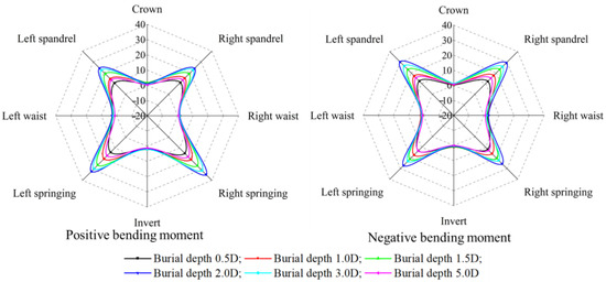
Figure 15.
Maximum bending moment of secondary lining (Different burial depths. Unit: kN·m).
Figure 14 and Figure 15 show that the distribution characteristics of bending moments for segmental lining and secondary lining are generally consistent under different burial depths, with larger values concentrated in the conjugate 45° regions and relatively smaller values elsewhere. The maximum positive bending moments for both the segmental lining and secondary lining occur in the springing, while the maximum negative bending moments occur in the spandrel.
The maximum bending moments under each burial depth are summarized in Figure 16.

Figure 16.
Variation curve of the maximum bending moments under different tunnel burial depths: (a) Segmental lining; (b) Secondary lining.
Figure 16 indicates that, as the burial depth increases, the bending moments initially increase and then decrease. For the segmental lining, the maximum positive bending moment is always greater than the maximum negative bending moment. When the tunnel burial depth increases from 0.5D to 2.0D, the maximum positive bending moment of the segmental lining increases from 112.52 kN·m to 165.31 kN·m, an increase of 46.9%, and the maximum negative bending moment increases from 97.67 kN·m to 144.27 kN·m, an increase of 47.7%, both showing a consistent rate of increase. By contrast, as the tunnel burial depth increases from 2D to 5D, the bending moments of the segmental lining gradually decrease. The maximum positive bending moment decreases from 165.31 kN·m to 143.58 kN·m, a decrease of 13.14%, and the maximum negative bending moment decreases from 144.27 kN·m to 115.43 kN·m, a decrease of 19.99%.
For the secondary lining, the maximum positive bending moment also consistently exceeds the maximum negative bending moment. When the tunnel burial depth increases from 0.5D to 2.0D, the maximum positive bending moment increases from 14.87 kN·m to 34.59 kN·m, an increase of 132.5%, and the maximum negative bending moment increases from 13.18 kN·m to 30.35 kN·m, an increase of 130.3%. When the tunnel burial depth increases from 2D to 5D, the maximum positive bending moment gradually decreases from 34.59 kN·m to 18.66 kN·m, a decrease of 46.07%, and the maximum negative bending moment decreases from 30.35 kN·m to 15.78 kN·m, a decrease of 48%.
As the tunnel burial depth increases, the ratio of the maximum bending moments between the segmental lining and secondary lining initially decreases and then increases. When the burial depths are 0.5D, 2D, and 5.0D, the ratios of the maximum positive bending moments are 7.56, 4.78, and 7.70, respectively, and the ratios of the maximum negative bending moment are 7.41, 4.75, and 7.31, respectively.
Based on the above analysis, it is evident that the maximum bending moments of the segmental lining are consistently greater than those of the secondary lining, and this pattern remains unchanged regardless of the changes in the burial depth. The segmental lining continues to serve as the primary load-bearing structure in the shield tunnel with double-layer lining. Furthermore, with the gradual increase in burial depth, the structural bending moments initially increase and then decrease, with the burial depth of 2D as the critical point, while the bending moment distribution ratio between the segmental lining and secondary lining initially decreases and then increases. The burial depth of 2D can be considered as the critical depth between shallow and deep burial depth. When the tunnel is in a shallow burial depth state, the overlying stratum has a significant influence on the seismic internal forces of the tunnel, and the internal forces continue to increase with the increasing burial depth. When the tunnel is in a deep burial depth state, it is securely confined by the surrounding stratum, making it relatively safer, and the internal forces on the tunnel continue to decrease with the increasing burial depth.
5.2.2. Structural Axial Force
The maximum axial forces of the segmental lining and secondary lining under different burial depths are illustrated in Figure 17.
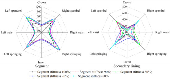
Figure 17.
Maximum axial force of tunnel structure (Different burial depths. Unit: kN).
Figure 17 shows that as the tunnel burial depth increases, the axial force distribution pattern of both the segmental lining and secondary lining remains largely unchanged, with higher axial forces in the springing and spandrel regions.
The maximum axial forces for each condition are summarized in Figure 18.
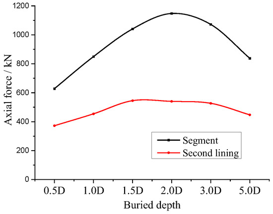
Figure 18.
Variation curve of the maximum axial force under different burial depths.
Both the segmental lining and secondary lining exhibit a trend where the maximum axial forces initially increase and then decrease with increasing burial depth, while the minimum axial forces show no significant change. For the segmental lining, the maximum axial force occurs in the right springing. When the tunnel burial depth increases from 0.5D to 2.0D, the axial force at the right arch foot increases from 627.99 kN to 1147.33 kN, an increase of 82.69%. However, as the tunnel burial depth increases from 2.0D to 5.0D, the axial force in the right springing decreases from 1147.33 kN to 837.54 kN, a reduction of 25.25%.
For the secondary lining, when the tunnel burial depth increases from 0.5D to 2.0D, the maximum axial force increases from 371.99 kN to 540.17 kN, an increase of 45.2%. Conversely, when the tunnel burial depth increases from 2.0D to 5.0D, the maximum axial force decreases from 540.17 kN to 447.16 kN, a reduction of 17.2%.
The burial depth of 2D can be considered as the critical depth between shallow and deep burial depth. When the tunnel is in a shallow burial depth state, the overlying stratum has a significant influence on the seismic internal forces of the tunnel, and the internal forces continue to increase with the increasing burial depth. When the tunnel is in a deep burial depth state, it is securely confined by the surrounding stratum, making it relatively safer, and the internal forces on the tunnel continue to decrease with the increasing burial depth. The segmental lining and secondary lining undergo uncoordinated deformation under different burial depths, resulting in differences in the axial force distribution between them. The variation of axial forces in the segmental lining is more significant with increasing burial depth.
The ratios of the maximum axial forces between the segmental lining and secondary lining for each condition are summarized in Figure 19.
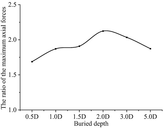
Figure 19.
The ratios of the maximum axial forces between the segmental and secondary lining.
Figure 18 shows that as the tunnel burial depth gradually increases, the ratio of the maximum axial forces between the segmental lining and secondary lining exhibits a trend of initially increasing and then decreasing. When the burial depth increases from 0.5D to 2.0D, the ratios rapidly increase from 1.69 to 2.21. However, when the burial depth increases from 2.0D to 3.0D, the ratios rapidly decrease from 2.21 to 2.03, and it gradually decreases to 1.87 as the burial depth increases to 5.0D. It can be seen that in shallow burial depth conditions (<2D), with increasing burial depth, the axial force on the segmental lining gradually increases in comparison to the secondary lining, eventually reaching more than twice the axial force of the secondary lining. In deep burial depth conditions (>2D), as the burial depth increases, the axial force on the segmental lining decreases gradually in comparison to the secondary lining but always remains at least 1.5 times greater than the secondary lining, indicating that the axial force on the segmental lining consistently remains dominant.
In summary, with the increase in tunnel burial depth, the uncoordinated deformation between the segmental lining and secondary linings leads to significant changes in the axial force distribution ratio.
6. Conclusions
Under the influence of strong earthquakes, shield tunnels are at risk of structural damage. The use of a double-layer lining structure helps to improve their seismic performance. In this research, using the Shiziyang Shield Tunnel as a case study, the numerical simulation method is employed to investigate the seismic response characteristics of a shield tunnel with overlapped double-layer lining. The following conclusions are drawn:
- The tunnel structure and surrounding stratum exhibit an increasing trend in acceleration amplification factors from the invert to the crown. Due to the intense interaction between the surrounding stratum and segmental lining, their acceleration amplification factors at the corresponding characteristic positions are nearly identical.
- The stresses in the segmental lining are greater than those in the secondary lining at all locations, with peak stresses occurring in the right springing. The stress in the segmental lining at this location is 2.61 MPa, while it is 0.87 MPa in the secondary lining, indicating an approximately threefold difference. This suggests that the segment remains the primary load-bearing structure under seismic loads.
- As the stiffness of the segmental lining decreases, its bending moment gradually decreases, while the bending moment in the secondary lining remains almost unchanged. The bending moment in the segmental lining consistently exceeds that in the secondary lining. When the segmental lining stiffness decreases from 100% to 60%, the maximum positive bending moment ratios decrease from 4.77 to 2.86, a reduction of 40.04%, indicating a significant change in load distribution under seismic loads. Additionally, the axial force in the segmental lining does not change significantly, but the axial force in the secondary lining decreases markedly.
- With increasing burial depth, the bending moment of the tunnel structure initially increases and then decreases. When the burial depths are 0.5D, 2D, and 5.0D, the ratios of the maximum positive bending moment between the segmental lining and secondary lining initially decrease and then increase, which are 7.56, 4.78, and 7.70, respectively. The segmental lining remains the primary load-bearing structure in the shield tunnel with double-layer lining.
- Increasing the segmental lining stiffness in shield tunnels is beneficial for enhancing seismic performance. Additionally, seismic internal forces in the shield tunnel reach their maximum value at a burial depth of 2D. Therefore, while ensuring structural safety, efforts should be made to maximize the burial depth of the tunnel (>2D).
Author Contributions
Conceptualization, X.G. and Q.C.; software, X.G.; writing—original draft preparation, X.G.; writing—review and editing, Q.C.; project administration, X.G.; funding acquisition, X.G. and Q.C. All authors have read and agreed to the published version of the manuscript.
Funding
This research was funded by the National Natural Science Foundation of China (Grant numbers 52308400 and 52378342) and the Funds of Scientific and Technological Plan of Fujian Province (Grant number 2022Y4015).
Institutional Review Board Statement
Not applicable.
Informed Consent Statement
Not applicable.
Data Availability Statement
The raw data supporting the conclusions of this article will be made available by the correspondence author on request.
Acknowledgments
We thank Junbin Liao (China Construction Yipin Investment and Development Co., Ltd.) and Zhicong Chen (Xiamen Metro Construction Co., Ltd., Xiamen, China) for their assistance in engineering background and design.
Conflicts of Interest
The authors declare no conflicts of interest.
References
- Pitilakis, K.; Tsinidis, G.; Leanza, A.; Maugeri, M. Seismic behaviour of circular tunnels accounting for above ground structures interaction effects. Soil. Dyn. Earthq. Eng. 2014, 67, 1–15. [Google Scholar] [CrossRef]
- Zou, Y.; Zhang, Y.; Liu, H.; Liu, H.; Miao, Y. Performance-based seismic assessment of shield tunnels by incorporating a nonlinear pseudostatic analysis approach for the soil-tunnel interaction. Tunn. Undergr. Space Technol. 2021, 114, 103981. [Google Scholar] [CrossRef]
- Shen, Y.; Zhong, Z.; Li, L.; Du, X.; Hesham El Naggar, M. Seismic response of shield tunnel structure embedded in soil deposit with liquefiable interlayer. Comput. Geotech. 2022, 152, 105015. [Google Scholar] [CrossRef]
- Zhang, S.; Yang, Y.; Yuan, Y.; Li, C.; Qiu, J. Experimental investigation of seismic performance of shield tunnel under near-field ground motion. Structures 2022, 43, 1407–1421. [Google Scholar] [CrossRef]
- Wu, H.; Ye, Z.; Zhang, Y.; Liu, H.; Liu, H. Seismic response of a shield tunnel crossing saturated sand deposits with different relative densities. Soil. Dyn. Earthq. Eng. 2023, 166, 107790. [Google Scholar] [CrossRef]
- Sun, F.; Shi, L.; Wang, J.; Wang, G. Seismic response analysis of close-distance cross tunnels: Shaking table test and numerical parameter analysis. Structures 2023, 50, 1670–1685. [Google Scholar] [CrossRef]
- Liu, C.; Peng, Z.; Cui, J.; Huang, X.; Li, Y.; Chen, W. Development of crack and damage in shield tunnel lining under seismic loading: Refined 3D finite element modeling and analyses. Thin Wall Struct. 2023, 185, 110647. [Google Scholar] [CrossRef]
- Wang, J.; Liu, H. Transverse seismic responses of a shield tunnel considering the influence of segment joints. Tunn. Undergr. Space Technol. 2023, 142, 105423. [Google Scholar] [CrossRef]
- Xu, L.; Guo, J.; Xu, C.; Chen, R.; Lin, J. Study on Dynamic Response of Soil Layer at the Bottom of Subway Shield Tunnel Under Seismic Action. Geotech. Geol. Eng. 2023, 41, 1635–1646. [Google Scholar] [CrossRef]
- Zhao, Z.; Cui, J.; Liu, C.; Liu, H.; Rehman, M.U.; Chen, W.; Peng, Z. Seismic damage characteristics of large-diameter shield tunnel lining under extreme-intensity earthquake. Soil. Dyn. Earthq. Eng. 2023, 171, 107958. [Google Scholar] [CrossRef]
- Yan, Q.; Yao, C.; Yang, W.; He, C.; Geng, P. An Improved Numerical Model of Shield Tunnel with Double Lining and Its Applications. Adv. Mater. Sci. Eng. 2015, 2015, 430879. [Google Scholar] [CrossRef]
- Yang, F.; Cao, S.; Qin, G. Mechanical behavior of two kinds of prestressed composite linings: A case study of the Yellow River Crossing Tunnel in China. Tunn. Undergr. Space Technol. 2018, 79, 96–109. [Google Scholar] [CrossRef]
- Wang, S.; Ruan, L.; Shen, X.; Dong, W. Investigation of the mechanical properties of double lining structure of shield tunnel with different joint surface. Tunn. Undergr. Space Technol. 2019, 90, 404–419. [Google Scholar] [CrossRef]
- Wang, S.; Jian, Y.; Lu, X.; Ruan, L.; Dong, W.; Feng, K. Study on load distribution characteristics of secondary lining of shield under different construction time. Tunn. Undergr. Space Technol. 2019, 89, 25–37. [Google Scholar] [CrossRef]
- Guo, R.; Zhang, M.; Xie, H.; He, C.; Fang, Y.; Wang, S. Model test study of the mechanical characteristics of the lining structure for an urban deep drainage shield tunnel. Tunn. Undergr. Space Technol. 2019, 91, 103014. [Google Scholar] [CrossRef]
- Li, Z.; Li, J.; Lin, G. A precise radiation boundary method for dynamic response of a double-layered tunnel embedded in a layered half-space. J. Appl. Geophys. 2019, 162, 93–107. [Google Scholar] [CrossRef]
- Wang, Y.; Cao, R.; Pi, J.; Jiang, L.; Zhao, Y. Mechanical properties and analytic solutions of prestressed linings with un-bonded annular anchors under internal water loading. Tunn. Undergr. Space Technol. 2020, 97, 103244. [Google Scholar] [CrossRef]
- Zhang, D.; Bu, X.; Pang, J.; Zhou, W.; Jiang, Y.; Jia, K.; Yang, G. Soil effect on the bearing capacity of a double-lining structure under internal water pressure. J. Zhejiang Univ. A Sci. 2022, 23, 863–881. [Google Scholar] [CrossRef]
- Zhang, D.; Zhou, W.; Bu, X.; Jiang, Y.; Jia, K.; Yang, G. Failure mechanism and stiffness degradation of double lining with inner R/FRC lining subjected to internal water pressure. Tunn. Undergr. Space Technol. 2022, 130, 104737. [Google Scholar] [CrossRef]
- Wang, S.; Wang, Y.; Lin, Z.; Song, Z.; Wang, X.; Peng, X. Analysis of the influence of the thickness insufficiency in secondary lining on the mechanical properties of Double-layer lining of shield tunnel. Eng. Fail. Anal. 2022, 141, 106663. [Google Scholar] [CrossRef]
- Chai, S.; Yan, Y.; Hu, B.; Wang, H.; Hu, J.; Chen, J.; Fu, X.; Zhou, Y. The Optimization of Secondary Lining Construction Time for Shield Tunnels Based on Longitudinal Mechanical Properties. Appl. Sci. 2023, 13, 10772. [Google Scholar] [CrossRef]
- Mai, S.; Tang, X.; Lu, A.; Yan, Z.; He, H. Full-scale model test for the performance of DDS prestressed composite lining with SCC-NC of high internal pressure shield tunnel. Tunn. Undergr. Space Technol. 2024, 144, 105528. [Google Scholar] [CrossRef]
- Xin, C.L.; Wang, Z.Z.; Zhou, J.M.; Gao, B. Shaking table tests on seismic behavior of polypropylene fiber reinforced concrete tunnel lining. Tunn. Undergr. Space Technol. 2019, 88, 1–15. [Google Scholar] [CrossRef]
- Zhou, T.; Dong, C.; Fu, Z.; Li, S. Study on Seismic Response and Damping Performance of Tunnels with Double Shock Absorption Layer. KSCE J. Civ. Eng. 2022, 26, 2490–2508. [Google Scholar] [CrossRef]
- Zhang, S.; Yuan, Y.; Yang, Y.; Li, C.; Yu, H. Experimental investigation of seismic performance of segmental tunnel with secondary lining under strong earthquake. Structures 2024, 60, 105833. [Google Scholar] [CrossRef]
- Koizumi, A. Segment Design of Shield Tunnel, 1st ed.; China Architecture & Building Press: Beijing, China, 2012; pp. 57–58. [Google Scholar]
- Zhang, X. Research on the Route Scheme of Shiziyang Crossing Pearl River Project of Foshan-Dongguan Intercity Railway. J. Railw. Eng. Soc. 2020, 37, 35–39. [Google Scholar]
- Yu, H.; Chen, J.; Bobet, A.; Yuan, Y. Damage observation and assessment of the Longxi tunnel during the Wenchuan earthquake. Tunn. Undergr. Space Technol. 2016, 54, 102–116. [Google Scholar] [CrossRef]
- Zucca, M.; Valente, M. On the limitations of decoupled approach for the seismic behaviour evaluation of shallow multi-propped underground structures embedded in granular soils. Eng. Struct. 2020, 211, 110497. [Google Scholar] [CrossRef]


Disclaimer/Publisher’s Note: The statements, opinions and data contained in all publications are solely those of the individual author(s) and contributor(s) and not of MDPI and/or the editor(s). MDPI and/or the editor(s) disclaim responsibility for any injury to people or property resulting from any ideas, methods, instructions or products referred to in the content. |
© 2024 by the authors. Licensee MDPI, Basel, Switzerland. This article is an open access article distributed under the terms and conditions of the Creative Commons Attribution (CC BY) license (https://creativecommons.org/licenses/by/4.0/).