
Grout Diffusion Mechanism along the Pile Shaft during the Process of Pile Tip Post-Grouting in Sand

Abstract
:Featured Application
Abstract
1. Introduction
2. Experimental Materials
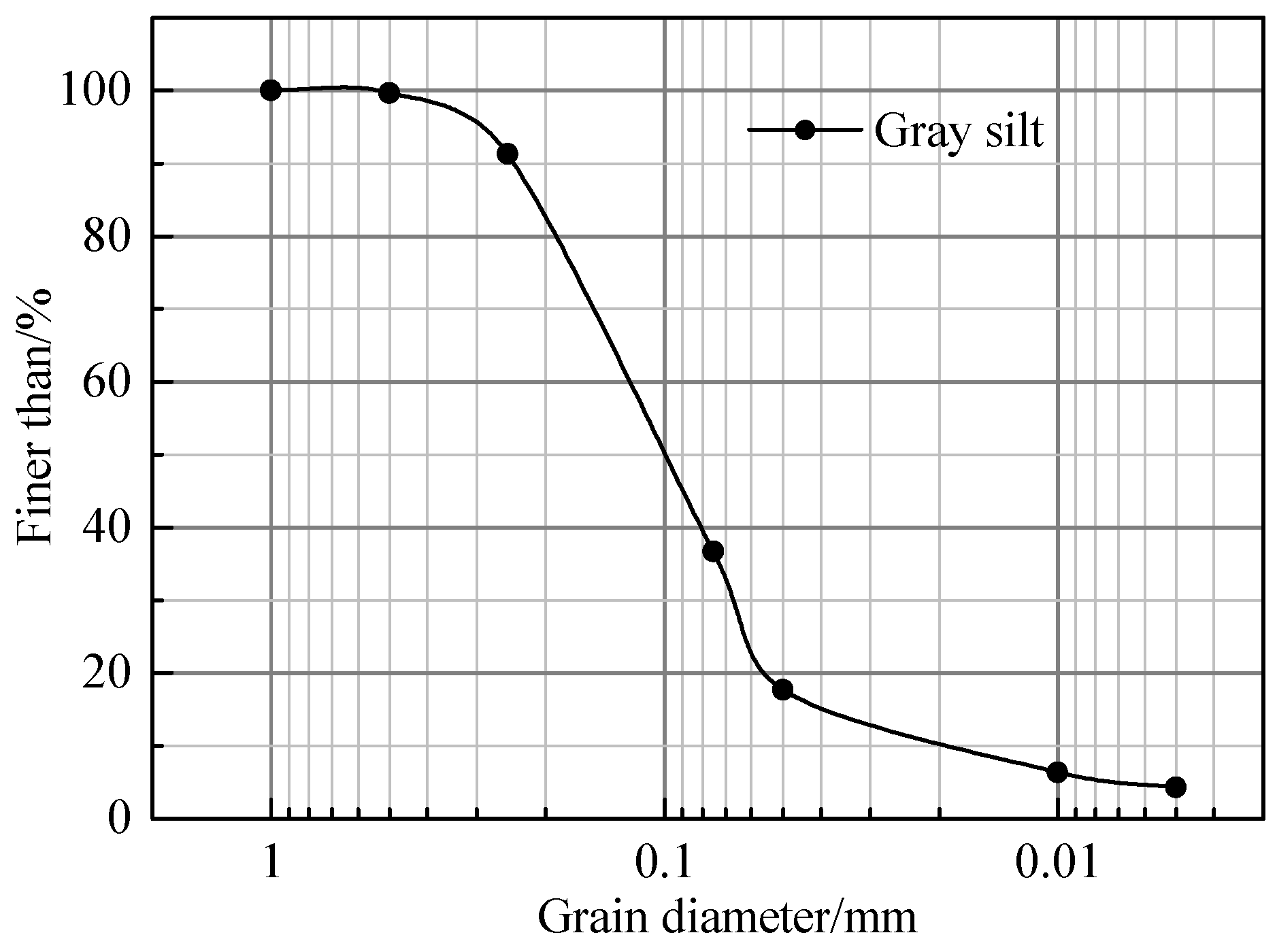
2.1. Sand
2.2. Cement
2.3. Concrete Plate
3. Experimental Methods
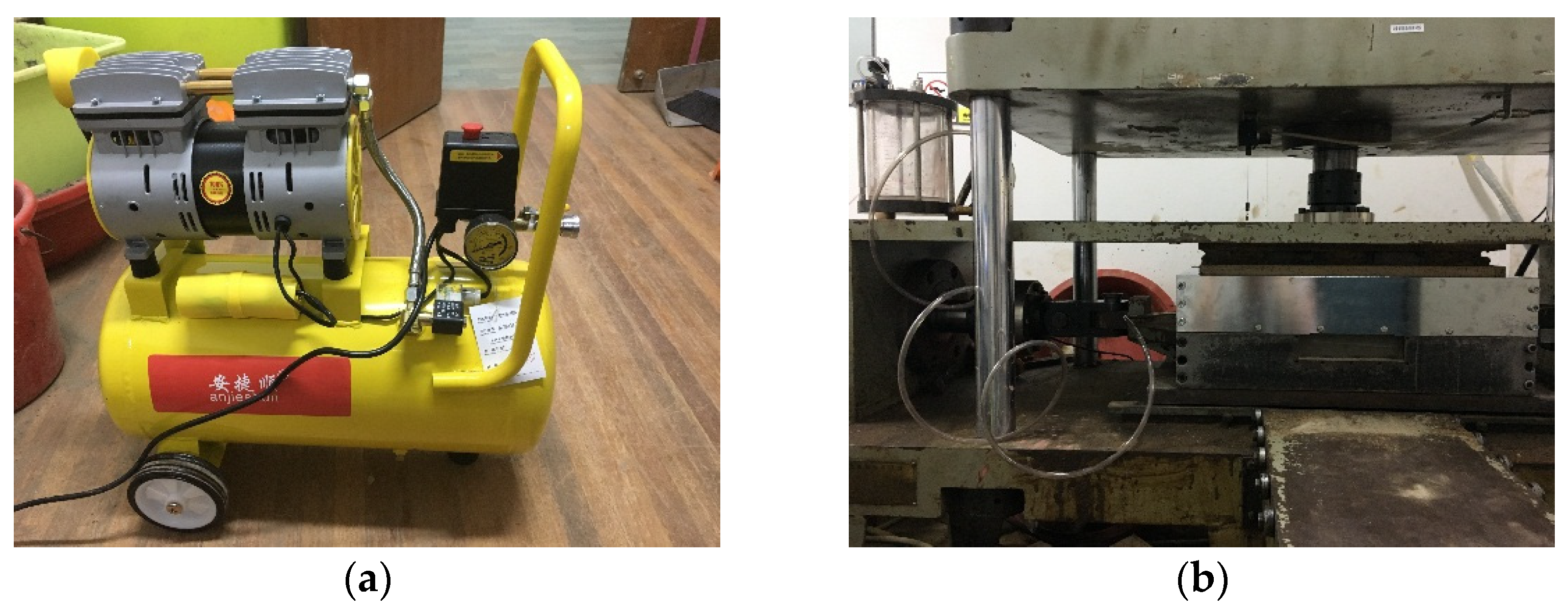
3.1. Test Apparatus
3.2. Test Program and Methods
3.3. Grout Diffusion Range and Mode
4. Experimental Results
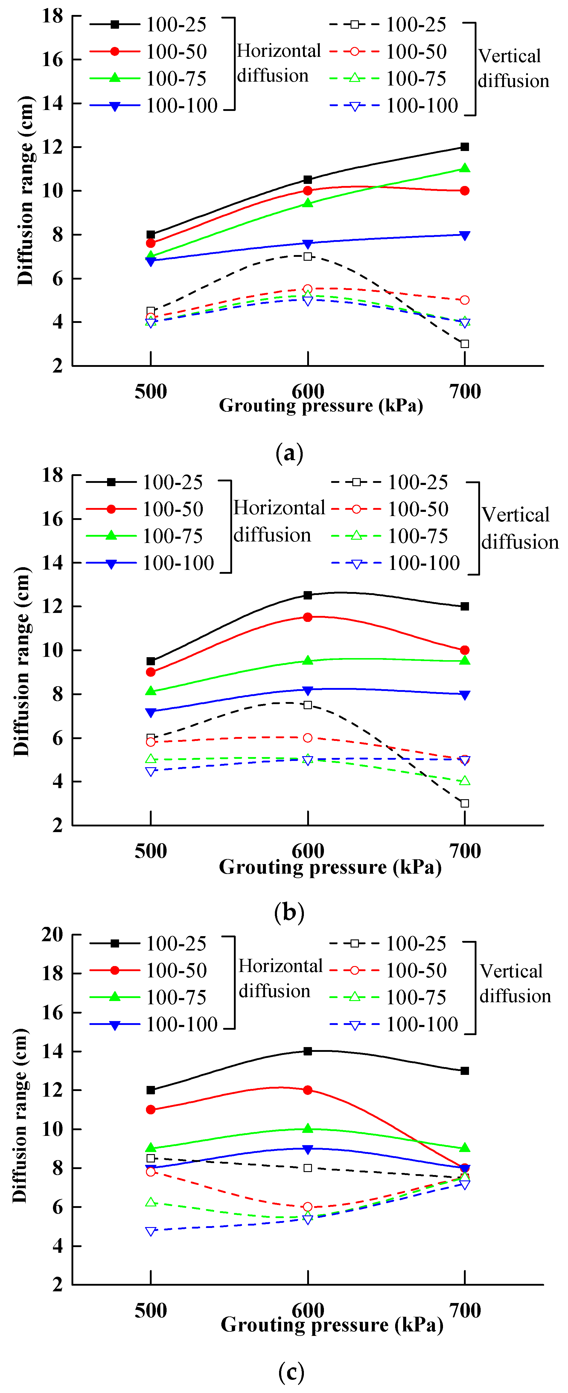
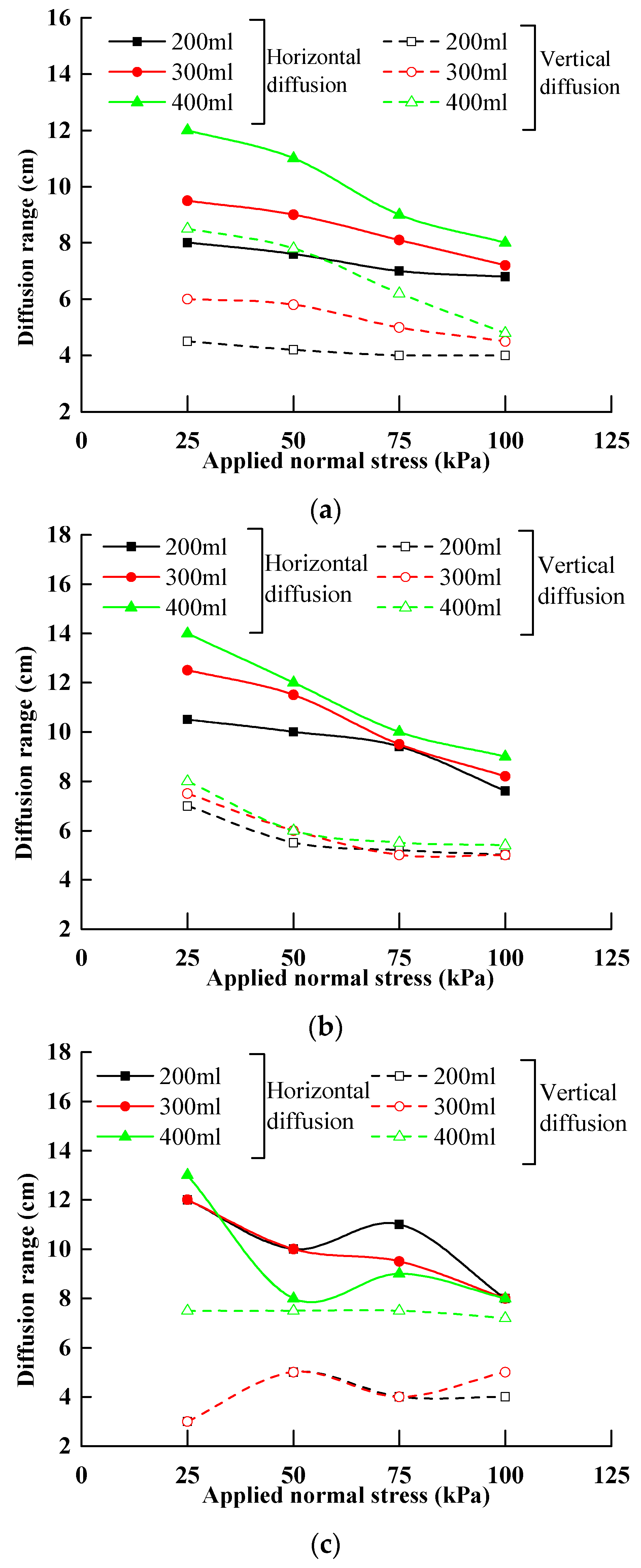
4.1. Effect of Grouting Pressure on the Grouting Diffusion Range
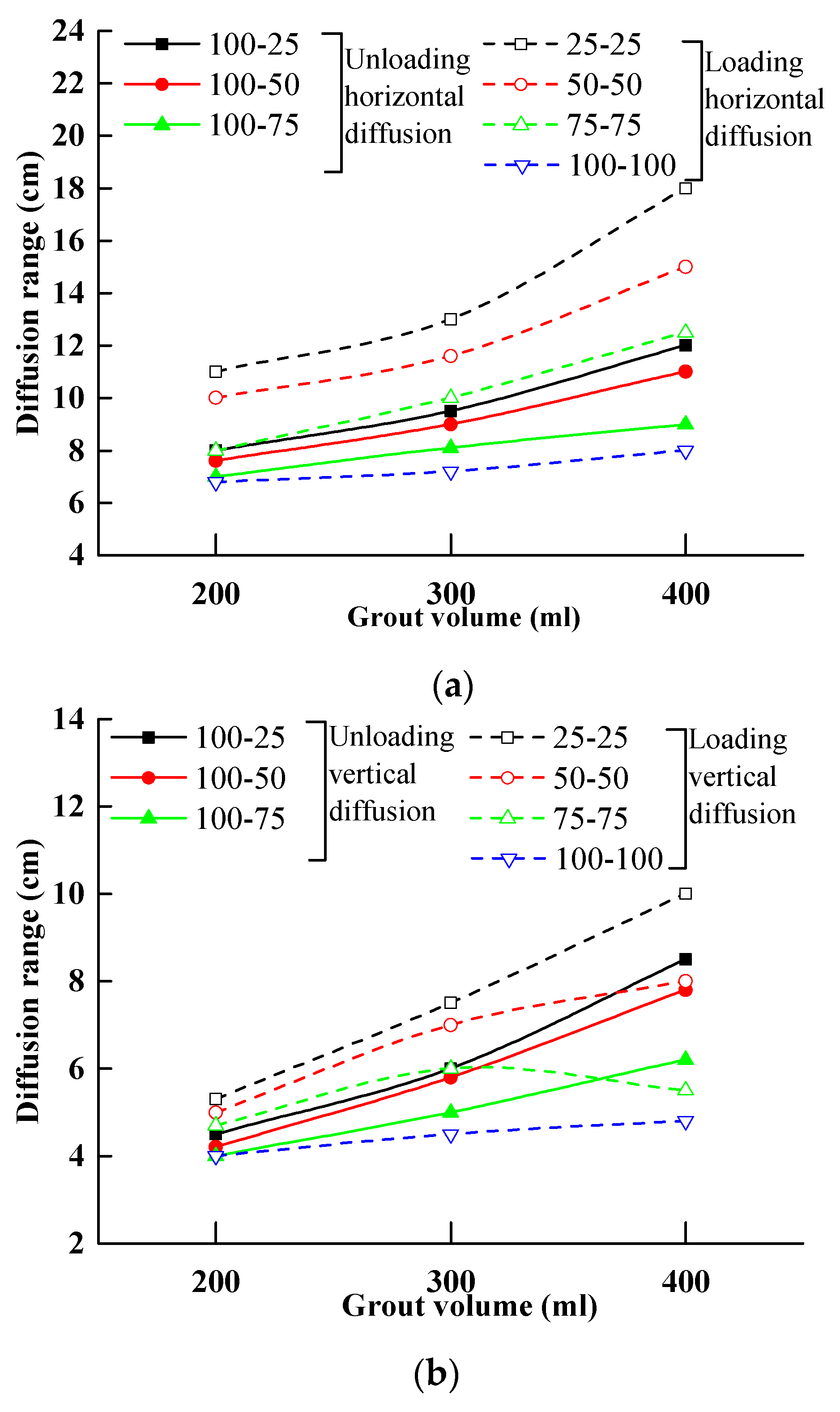
4.2. Effect of Grout Volume on the Grouting Diffusion Range
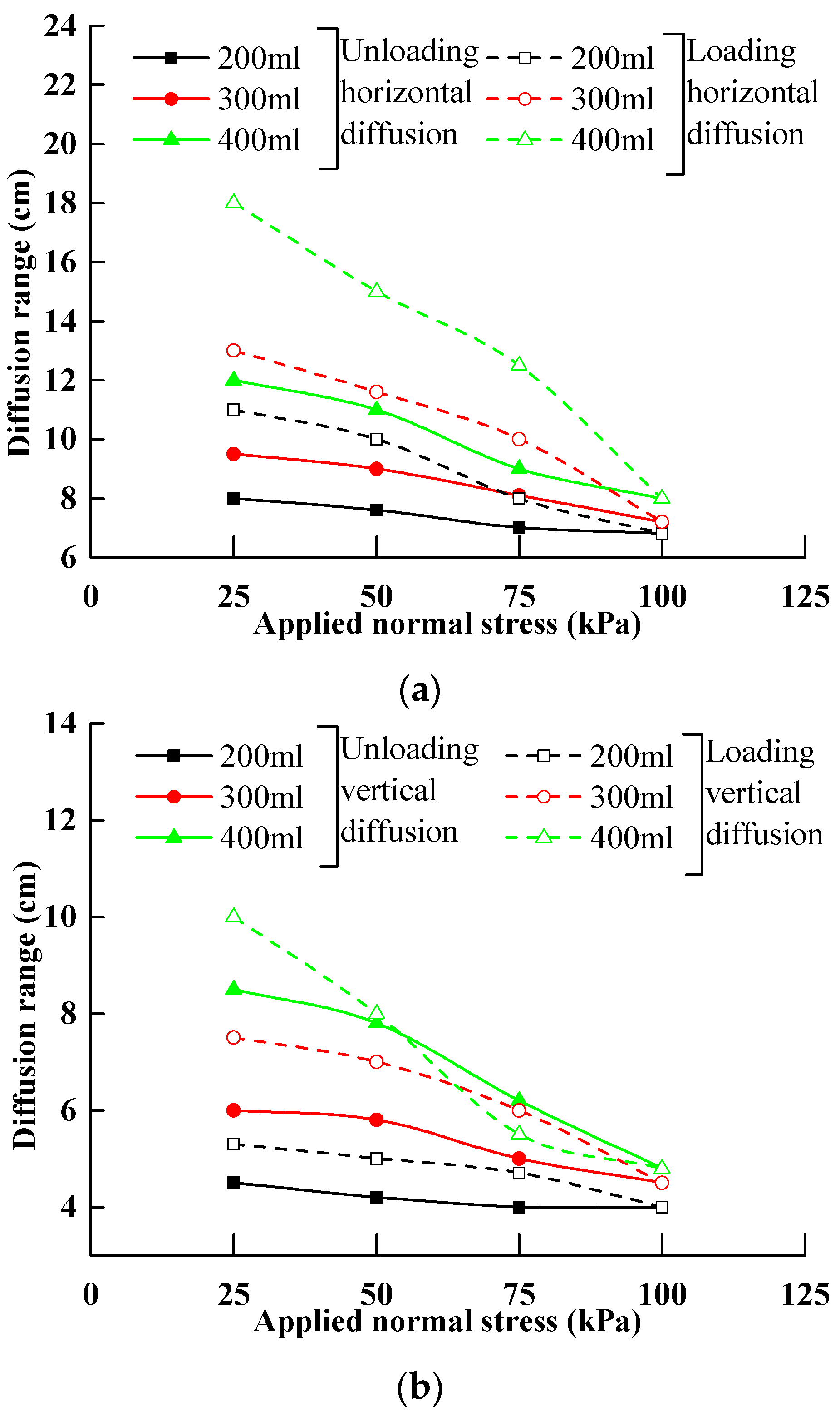
4.3. Effect of Soil Stress History on the Grouting Diffusion Range
4.4. Grout Diffusion Characteristics
5. Discussion and Interpretation
6. Conclusions
- The returned height increases non-linearly with increasing grouting pressure when the grout volume is low. With the increase of the grout volume, the returned height with increasing grouting pressure is not monotonic, and the threshold value is approximately 600 kPa. The radial expansion distance with increasing grouting pressure is also not monotonic, and the threshold value is also approximately 600 kPa.
- The returned height increases with the grout volume increased, but the radial expansion distance is maintained within the range of 5–8 cm for the grouting pressure at 500 kPa and 600 kPa. When the grouting pressure is 700 kPa, the relationship between the returned height and the grout volume is affected by the degree of unloading, but the radial expansion distance is affected by the grout volume.
- The grout diffusion range in the loading soil is higher than that in the unloading soil and the returned height is greater than the radial expansion distance under the same grouting pressure, grout volume, and the applied normal stress of the soil.
- Regardless of loading and unloading conditions in the soil stress history, the characteristic of the grouting cement returned along the pile body during the process of the pile tip post-grouting is mainly affected by the grouting pressure and the grout volume, whereas the transition of grouting mode is mainly affected by the grouting pressure.
- A simplified model to describe the grouting cement diffusion pattern and the corresponding grouting mode of grouting cement returned along the pile body during the process of pile tip post-grouting was proposed. This model can comprehensively reflect the grouting cement diffusion characteristics along the pile body, with different grouting and load conditions taken into account.
Author Contributions
Funding
Institutional Review Board Statement
Informed Consent Statement
Data Availability Statement
Conflicts of Interest
References
- Zhang, Q.Q.; Li, H.T.; Cui, W.; Zhao, Y.H.; Wang, S.L.; Xu, F. Analysis of grout diffusion of postgrouting pile considering the time-dependent behavior of grout viscosity. Int. J. Geomech. 2021, 21, 04021201. [Google Scholar] [CrossRef]
- Yin, X.L.; Wu, Z.J.; Xu, X.Y.; Weng, L.; Liu, Q.S. Numerical investigation on the grouting penetration process of quick-setting grout in discrete fractured rock mass based on the combined finite-discrete-element method. Int. J. Geomech. 2023, 24, 04023298. [Google Scholar] [CrossRef]
- Sha, F.; Zhang, L.Y.; Zhang, M.l.; Zuo, Y.H.; Niu, H.Y. Penetration grouting diffusion and strengthening mechanism of sand layer with crucial grout. J. Build. 2024, 91, 109585. [Google Scholar] [CrossRef]
- Wu, Y.; Zhao, C.; Zhao, C.F.; Liu, F.M.; Zhang, Z.Q. Modeling of compaction grouting considering the soil unloading effect. Int. J. Geomech. 2022, 22, 04022061. [Google Scholar] [CrossRef]
- Shrivastava, N.; Zen, K. Finite element modeling of compaction grouting on its densification and confining aspects. Geotech. Geol. Eng. 2018, 36, 2235–2378. [Google Scholar] [CrossRef]
- Brown, D.R.; Warner, J. Compaction grouting. J. Soil Mech. Found. 1973, 99, 589–601. [Google Scholar] [CrossRef]
- El-Kelesh, A.M.; Matsui, T.; Tokida, K.I. Field investigation into effectiveness of compaction grouting. J. Geotech. Geoenviron. Eng. 2012, 138, 451–460. [Google Scholar] [CrossRef]
- Seo, H.J.; Jeong, K.H.; Choi, H.; Lee, I.M. Pullout resistance increase of soil nailing induced by pressurized grouting. J. Geotech. Geoenviron. Eng. 2012, 138, 604–613. [Google Scholar] [CrossRef]
- Nichols, S.C.; Goodings, D.J. Physical model testing of compaction grouting in cohesionless soil. J. Geotech. Geoenviron. Eng. 2000, 126, 848–852. [Google Scholar] [CrossRef]
- Wang, Q.; Wang, S.; Sloan, S.W.; Sheng, D.; Pakzad, R. Experimental investigation of pressure grouting in sand. Soils Found. 2016, 56, 161–173. [Google Scholar] [CrossRef]
- Zhang, Z.M.; Jian, Z. Penetration radius and grouting pressure in fracture grouting. Chin. J. Geotech. Eng. 2008, 30, 181–184. [Google Scholar] [CrossRef]
- Zou, J.F.; Li, L.; Yang, X.L. Penetration radius and pressure attenuation law in fracturing grouting. J. Hydraul. Eng. 2006, 37, 314–319. [Google Scholar]
- Liang, J.S.; Du, X.m.; Fang, H.Y.; Li, B.; Wang, N.N.; Di, D.Y.; Xue, B.H.; Zhai, K.J.; Wang, S.Y. Intelligent prediction model of a polymer fracture grouting effect based on a genetic algorithm-optimized back propagation neural network. Tunn. Undergr. Space Technol. 2024, 148, 105781. [Google Scholar] [CrossRef]
- Zhang, L.Z.; Huang, C.X.; Li, Z.P.; Han, X.; Zhang, Q.S.; Gao, Y. Characteristics of slurry-water mixing region in fractured rock mass grouting process: Experimental study. Constr. Build Mater. 2024, 427, 136244. [Google Scholar] [CrossRef]
- Xiao, F.; Liu, Q.; Zhao, Z.Y.; Xiao, F.; Liu, Q.; Zhao, Z.Y. Information and knowledge behind data from underground rock grouting. J. Rock Mech. Geotech. Eng. 2021, 13, 1326–1339. [Google Scholar] [CrossRef]
- Yan, C.Z.; Wang, T.; Gao, Y.K.; Ke, W.H.; Wang, G. A three-dimensional grouting model considering hydromechanical coupling based on the combined finite-discrete element method. Int. J. Geomech. 2022, 22, 04022189. [Google Scholar] [CrossRef]
- JGJ 94-2008; Technical Code for Building Pile Foundations. China Architecture and Building Press: Beijing, China, 2008.
- JTG D63-2007; Code for Design of Ground Base and Foundation of Highway Bridges and Culverts. China Communications Press: Beijing, China, 2007.
- Mori, A.; Tamura, M.; Fukul, Y. Fracturing pressure of soil ground by viscous materials. Soils Found. 1990, 30, 129–136. [Google Scholar] [CrossRef]
- Mori, A.; Tamura, M.; Shibata, H.; Hayashi, H. Some factors related to injected shape in grouting. Grouting Soil Improv. Geosynth. 1992, 3, 313–324. [Google Scholar]
- Zhao, C.F.; Wu, Y.; Zhao, C.; Liu, F.M.; Liu, F. Effect of unloading on shear behavior of interface between sand and concrete. Chin. J. Rock Mech. Eng. 2018, 37, 1020–1029. [Google Scholar] [CrossRef]
- Bezuijen, A.; Tol, A.F.V. Compensation grouting in sand, fractures and compaction. In Proceedings of the XIV European Conference on Soil Mechanics and Geotechnical Engineering, Madrid, Spain, January 2007; pp. 1257–1262. [Google Scholar]
- Jafari, M.R.; Au, S.K.; Soga, K.; Bolton, M.D.; Karim, U.F.A.; Komiya, K. Experimental and numerical investigation of compensation grouting in clay. J. Appl. Microbiol. 2000, 17, 333–334. [Google Scholar]
- Komiya, K. Soil consolidation associated with grouting during shield tunnelling in soft clayey ground. Géotechnique 2001, 53, 447–448. [Google Scholar] [CrossRef]
- Zhao, C.F.; Wu, Y.; Zhao, C.; Zhang, Q.Z.; Liu, F.M.; Liu, F. Pile side resistance in sands for the unloading effect and modulus degradation. Mater. Constr. 2019, 69, 185. [Google Scholar] [CrossRef]
- Bezuijen, A.; Tol, A.F.V.; Sanders, M.P.M. Mechanisms that determine between fracture and compaction grouting in sand. In Aspects of Underground Construction in Soft Ground, Proceeding of the 6st International Symposium on Geotechnical Aspects of Underground Construction in Soft Ground, Shanghai, China, 10–14 April 2008; CRC Press: Boca Raton, FL, USA, 2021. [Google Scholar]
- Gafar, K.; Soga, K.; Bezuijen, A.; Sanders, M.P.M.; Tol, A.F.V. Fracturing of sand in compensation grouting. In Geotechnical Aspects of Underground Construction in Soft Ground; CRC Press: Boca Raton, FL, USA, 2009; Volume 156, pp. 117–123. [Google Scholar]
- Zhao, C.; Zhao, C.F.; Gong, H. Elastoplastical analysis of the interface between clay and concrete incorporating the effect of the normal stress history. J. Appl. Math. 2013, 12, 673057. [Google Scholar] [CrossRef]


| Unit Weight γ/(kN·m−3) | Internal Friction Angle φ/(°) | Water Content ω/% | Void Ratio e | Compression Modulus ES1–2/MPa |
|---|---|---|---|---|
| 19.5 | 31.5 | 20 | 0.754 | 11.23 |
| Grouting Pressure (kPa) | Grout Volume (mL) | Initial Normal Stress (kPa) | Applied Normal Stress (kPa) | ||
|---|---|---|---|---|---|
| 500 | 200 | 100 | 25 | 50 | 75 |
| 300 | 100 | 25 | 50 | 75 | |
| 400 | 100 | 25 | 50 | 75 | |
| 600 | 200 | 100 | 25 | 50 | 75 |
| 300 | 100 | 25 | 50 | 75 | |
| 400 | 100 | 25 | 50 | 75 | |
| 700 | 200 | 100 | 25 | 50 | 75 |
| 300 | 100 | 25 | 50 | 75 | |
| 400 | 100 | 25 | 50 | 75 | |
| Grouting Pressure (kPa) | Grout Volume (mL) | Normal Stress (kPa) | |||
|---|---|---|---|---|---|
| 500 | 200 | 25 | 50 | 75 | 100 |
| 300 | 25 | 50 | 75 | 100 | |
| 400 | 25 | 50 | 75 | 100 | |
| 600 | 200 | × | × | × | 100 |
| 300 | × | × | × | 100 | |
| 400 | × | × | × | 100 | |
| 700 | 200 | × | × | × | 100 |
| 300 | × | × | × | 100 | |
| 400 | × | × | × | 100 | |
| Grout Volume (mL) | Difference of the Returned Height (cm) | Difference of the Radial Expansion Distance (cm) | ||||||
|---|---|---|---|---|---|---|---|---|
| Load Conditions (kPa) | Load Conditions (kPa) | |||||||
| 100-25 | 100-50 | 100-75 | 100-100 | 100-25 | 100-50 | 100-75 | 100-100 | |
| 200 | 4 | 2.4 | 4 | 1.2 | −1.5 | 0.8 | 0 | 0 |
| 300 | 2.5 | 1 | 1.4 | 0.8 | −3 | −0.8 | −1 | 0.5 |
| 400 | 1 | −3 | 0 | 0 | −1 | −0.3 | 1.3 | 2.4 |
| Grouting Pressure (kPa) | Difference of the Returned Height (cm) | Difference of the Radial Expansion Distance (cm) | ||||||
|---|---|---|---|---|---|---|---|---|
| Load Conditions (kPa) | Load Conditions (kPa) | |||||||
| 100-25 | 100-50 | 100-75 | 100-100 | 100-25 | 100-50 | 100-75 | 100-100 | |
| 500 | 4 | 3.4 | 2 | 1.2 | 4 | 2.4 | 2.2 | 0.8 |
| 600 | 3.5 | 2 | 0.6 | 1.4 | 1 | 0.5 | 0.3 | 0.4 |
| 700 | 1 | −2 | 2 | 0 | 4.5 | 2.5 | 3.5 | 3.2 |
| Grout Volume (mL) | Grouting Pressure (kPa) | Digital Photos | Horizontal Diffusion Grout Distance (cm) | Vertical Diffusion Grout Distance (cm) | Main Features |
|---|---|---|---|---|---|
| 200 | 500 | 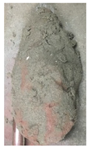 | 8 | 4.5 | Compaction grouting; Half-droplet shape |
| 600 | 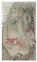 | 10.5 | 7 | Compaction grouting; Similar to a half-droplet shape | |
| 700 | 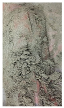 | 12 | 3 | Compaction dominant; Long and narrow strip shape | |
| 300 | 500 |  | 9.5 | 6 | Compaction grouting; Half-droplet shape |
| 600 | 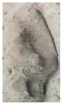 | 12.5 | 7.5 | Compaction dominant; Thick and short grout veins in the horizontal and lateral directions | |
| 700 | 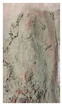 | 12 | 3 | Compaction dominant; Thick and short grout veins in the horizontal and lateral directions | |
| 400 | 500 | 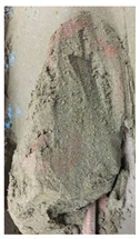 | 12 | 8.5 | Compaction grouting; combination of a semi-cylindrical body and a semi-cone body |
| 600 | 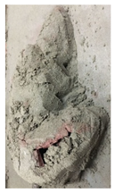 | 14 | 8 | Compaction and fracture; Grout bulb crack tip in the horizontal direction, thick and short grout veins, and grout bulb shell in the lateral direction | |
| 700 | 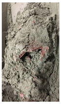 | 13 | 7.5 | Fracture dominant; Obviously, grout bulb shell and cracked surface morphology existed |
| Grout Volume (mL) | Grouting Pressure (kPa) | Digital Photos | Horizontal Diffusion Grout Distance (cm) | Vertical Diffusion Grout Distance (cm) | Main Features |
|---|---|---|---|---|---|
| 200 | 500 | 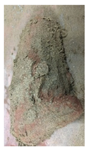 | 6.8 | 4 | Compaction grouting; Half-droplet shape |
| 600 |  | 7.6 | 5 | Compaction grouting; Long and narrow half-droplet shape | |
| 700 | 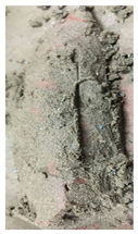 | 8 | 4 | Compaction grouting; Long and narrow strip shape | |
| 300 | 500 | 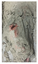 | 7.2 | 4.5 | Compaction grouting; Wide and short half-ellipsoidal shape |
| 600 |  | 8.2 | 5 | Compaction dominant; Irregular in shape, similar to a double half-spherical shape | |
| 700 |  | 8 | 5 | Compaction and fracture; Half-spherical shape closing to the grouting hole and thick and short grout veins away from the grouting hole | |
| 400 | 500 | 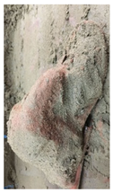 | 8 | 4.8 | Compaction dominant; Grout bulb gathered on the grouting hole like ancient bell and sheet shape away from the grouting hole |
| 600 |  | 9 | 5.4 | Compaction and fracture; Broad and long of grout bulb with short and thick veins and grout bulb shells on the tail and sides of the grout bulb. | |
| 700 | 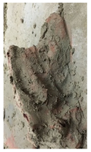 | 8 | 7.2 | Fracture dominant; Similar to the “ball snout” at the bottom of the ship, an obvious grout bulb shell and cracked surface morphology existed |
Disclaimer/Publisher’s Note: The statements, opinions and data contained in all publications are solely those of the individual author(s) and contributor(s) and not of MDPI and/or the editor(s). MDPI and/or the editor(s) disclaim responsibility for any injury to people or property resulting from any ideas, methods, instructions or products referred to in the content. |
© 2024 by the authors. Licensee MDPI, Basel, Switzerland. This article is an open access article distributed under the terms and conditions of the Creative Commons Attribution (CC BY) license (https://creativecommons.org/licenses/by/4.0/).
Share and Cite
Wu, Y.; Deng, Y.; Zhang, X.; Liu, L.; Zhao, C.; Zhang, J. Grout Diffusion Mechanism along the Pile Shaft during the Process of Pile Tip Post-Grouting in Sand. Appl. Sci. 2024, 14, 5389. https://doi.org/10.3390/app14135389
Wu Y, Deng Y, Zhang X, Liu L, Zhao C, Zhang J. Grout Diffusion Mechanism along the Pile Shaft during the Process of Pile Tip Post-Grouting in Sand. Applied Sciences. 2024; 14(13):5389. https://doi.org/10.3390/app14135389
Chicago/Turabian StyleWu, Yue, Yating Deng, Xuefu Zhang, Lang Liu, Chunfeng Zhao, and Jiaqi Zhang. 2024. "Grout Diffusion Mechanism along the Pile Shaft during the Process of Pile Tip Post-Grouting in Sand" Applied Sciences 14, no. 13: 5389. https://doi.org/10.3390/app14135389