Article

Numerical Analysis of Tooth Contact and Wear Characteristics of Internal Cylindrical Gears with Curved Meshing Line

School of Mechanical Engineering and Automation, Fuzhou University, Fuzhou 350108, China
*
Author to whom correspondence should be addressed.
Appl. Sci. 2024, 14(13), 5399; https://doi.org/10.3390/app14135399
Submission received: 28 April 2024 / Revised: 18 June 2024 / Accepted: 19 June 2024 / Published: 21 June 2024

Abstract

:
In order to improve the contact strength and reduce the sliding friction of the gear pair, an internal cylindrical gear pair with a curved meshing line is studied in this paper. Firstly, a curved meshing line is designed. The tooth profiles of the internal gear pair with the designed meshing line are calculated by using differential geometry and the gear meshing principle. Secondly, a wear model is established by combining the finite element method and the Archard wear formula. Then, a numerical simulation is conducted; the relative curvature, sliding coefficient, sliding distance, maximum contact pressure, transmission error, and wear depth are calculated. Ultimately, the variation law of tooth surface wear of new gear with and without installation errors is observed under different stress cycles. On this basis, the influence of tooth modification on tooth surface wear is further researched. Through the results, the advantages of the introduced novel internal cylindrical gears in wear resistance are further demonstrated. The study in this paper provides new research ideas and methods for gear wear research and gear design.

1. Introduction

Planetary gear trains are widely used in modern power transmission systems, and their performance directly affects the quality level of the mechanical equipment. Internal meshing gears are an integral part of the planetary gear train, and studying internal meshing gears is of great significance for planetary gear trains.
Tooth surface wear of gears is an inevitable phenomenon in the transmission process. Severe tooth surface wear will reduce the thickness of the tooth surface, further weaken the bearing capacity of the gear, and even lead to serious accidents such as broken teeth, which will cause the equipment to fail to work. As is well known, the tooth surface profile can determine the performance of gears to some extent. By changing the geometric shape of the tooth surface, the meshing performance of the gears can be improved. Therefore, exploring new tooth profiles and studying the contact and wear characteristics of new gears is another effective way to improve the quality and service life of gear transmission systems.
For a long time, researchers both domestically and internationally have conducted extensive research on gear wear from multiple perspectives. Higher-order tooth surface modification is a relatively novel method which has attracted the attention of researchers in the industry [1]. Through high-order modification, tooth surface contact stress can be decreased, which will lessen tooth surface wear. Rai et al. [2] demonstrated that appropriate profile modifications can balance specific sliding conditions, improving the wear resistance and anti-scuffing capability of helical gear pairs. Chen et al. [3] investigated the competitive relationship between tooth profile modifications and wear, as well as the impact on mesh stiffness and transmission error. Sánchez and Pleguezuelos et al. [4,5] found that the length, depth, and shape of gear modification will affect the load distribution and transmission error, thus affecting the entire wear process. Tunalioglu et al. [6] discovered that modifying the tooth profile of internal gears can reduce wear in the top area of the tooth. Gołębski et al. [7] investigated the modification problem of spur gears and proposed a step-by-step processing method for large module gears applicable to arbitrary modification systems. NARAZAKI et al. [8] discussed the influence of tooth profile modification on the tooth wear of involute spur gears. Abdul et al. [9] researched the impact of different tooth profile modifications (linear, parabolic, and exponential) on the internal spur gear pairs’ performance utilizing a hybrid analysis approach combining contact mechanics and finite elements. Li et al. [10] considered tooth profile modification, proposed a theoretical model of tooth surface wear for cycloid pinwheel pair, and deeply analyzed the tooth surface wear mechanism of cycloidal transmission. Zhang et al. [11] introduced a new method for modifying special gear trains and verified the effectiveness of the optimization method through numerical examples. Issayeva et al. [12] optimized involute gear parameters through gear modification to enhance the load-bearing capacity and reliability of the gear, addressing the severe wear problem of gears in ball mills. In order to compensate for the negative impact of misalignment, Zhang et al. [13] proposed an involute crown modification strategy and verified its effectiveness in improving contact distribution and wear through wear depth prediction. Park et al. [14] explored the influence of tooth profile and surface roughness on spur gear wear under temperature factors. Chernets and De T et al. [15,16] examined the effects of tooth profile modification and friction coupling on spur gear wear. As the gears continue to operate, wear problems are inevitable, and the continued wear of the gears will inevitably lead to changes in the gear tooth profile. Chen et al. [17] established a wear evolution model of gear tooth profile changes caused by cumulative wear. Zhang et al. [18] studied the wear and contact fatigue of involute modified gears under minimum-quantity lubrication by updating the contact path and gear profile in real time. Simultaneously, Feng and Zhang et al. [19,20], respectively, predicted the wear resulting from tooth profile changes to mitigate failures and minimize economic losses. The magnitude of the modification coefficient has different effects on gear wear, and the optimal modification coefficient can significantly prolong the gear’s service life [21]. Therefore, Sekar et al. [22] investigated the influence of different tooth profile correction coefficients on the wear depth of asymmetric spur gears. Sánchez et al. [23] studied the variation in transmission error with the number of wear cycles and discussed the optimal contour correction required to minimize the transmission error. Moreover, Xiao et al. [24] studied the lubrication and wear performance of modified heavy-duty herringbone gears during the complete operating cycle from start to stop. Huangfu et al. [25] explored the effect of tooth profile modification on the dynamic characteristics of thin-edge gear surface wear. Additionally, researchers also started from the perspective of optimizing the tool and modified the tooth surface by changing the tooth shape of the tool, thereby improving the wear resistance of the gear [26,27,28].
From the above discussion, it can be shown that most of the current research on tooth surface wear has mainly focused on involute cylindrical gears; there is still relatively little research on gears with curved meshing lines. The reason is that involute gears occupy a dominant position in general industry and are widely used. In addition, the geometric structure of the tooth surface of gears with curved meshing lines is relatively complicated. However, with the development of industrial technology, engineering equipment has put forward higher requirements for gear transmission systems. In some high load-bearing engineering equipment, such as coal mining machines and shield tunneling machines, involute gears gradually expose problems such as low tooth contact strength and high sliding friction.
Therefore, in order to meet the needs of modern industry in some special fields, such as the mining and construction industries, this paper studies an internal meshing cylindrical gear with a curved meshing line and deeply researches its tooth contact and wear characteristics through simulation modeling. The relative curvature, sliding coefficient, sliding distance, maximum contact pressure, transmission error, and wear depth of the designed gears are calculated based on the established model. The advantages of the internal meshing cylindrical gears with curved meshing lines in these aspects are demonstrated via comparison with involute ones. The research of this paper can lay a solid foundation for the design and development of a novel planetary gear train with a curved meshing line.

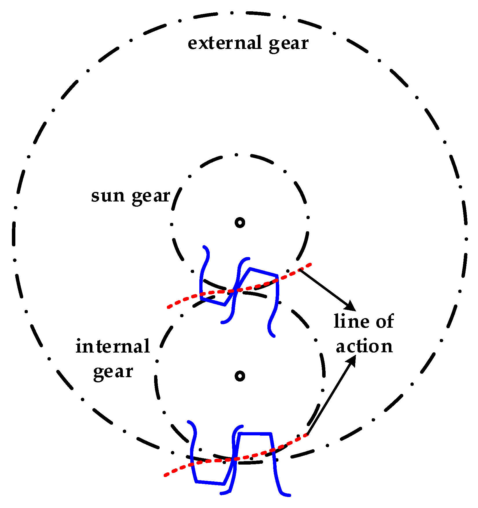
2. Designation of Tooth Profile of Internal Gears with Curved Meshing Lines

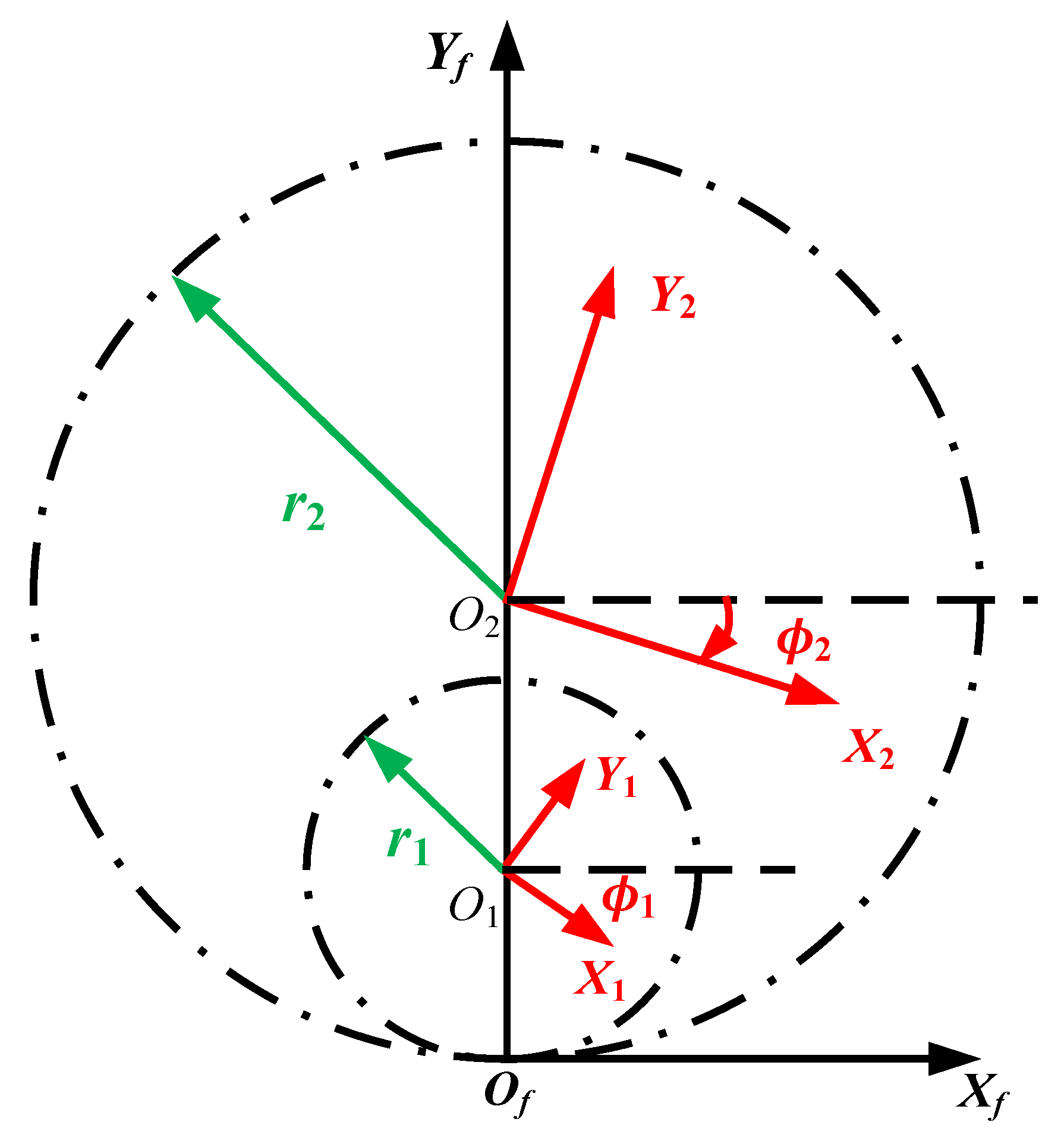
2.1. Designation of Curved Meshing Line

As shown in Figure 1, In a planetary gear train, the meshing lines of the external and internal gear pairs need to be consistent to achieve the correct meshing of the planetary gear train. The curved meshing line internal meshing cylindrical gear proposed in this paper is a part of the planetary gear system, together with the curved meshing line external meshing cylindrical gear proposed in reference [29], which forms a curved meshing line planetary gear train. Therefore, the construction method of the meshing line of the internal meshing gear in this thesis is the same as that of reference [29], but only differs in the length of the meshing line.
As shown in Figure 2, the curved meshing line consists of two parabolas located in the first and third quadrants. Point F1 (0, p1/2) is the focal point of the parabola in the first quadrant, while point F2 (0, −p2/2) is the focal point of the parabola in the third quadrant. The meshing line intersects with the internal gear tooth apex circle at point D1 and the external gear tooth apex circle at point D2.
Based on the construction method in reference [29], the meshing line located in the first quadrant can be expressed by the following equation:
x f = p 1 sin u t 1 sin u t y f = p 1 sin u t 2 1 sin u t
The meshing line located in the third quadrant can be expressed by the following equation:
x f = p 2 sin u t 1 sin u t y f = p 2 sin u t 2 1 sin u t
where u t is the meshing line parameter (Appendix A). Also, the following defines dimensionless parameters:
k 1 = p 1 / 2 r 1               k 2 = p 2 / 2 r
where r1 is the external gear pitch radius and r is the sun gear pitch radius.

2.2. Derivation of Internal Gear Tooth Profiles

As shown in Figure 3, coordinate systems Si (i = 1, 2) and Sf are established, where Si (i = 1, 2) is a coordinate system fixedly connected to the external gear and internal gear, respectively, and the coordinate origin Oi (i = 1, 2) is located at the centers of the two gears. Sf is a fixed coordinate system, with the coordinate origin Of located at the tangent point of the two gear pitch circles.
According to the principle of gear internal meshing and coordinate transformation, the external gear tooth profile equation r 1 and the internal gear tooth profile equation r 2 can be expressed by the following equations, respectively:
r 1 ( u t ) = x f ( u t ) cos ϕ 1 ( u t ) y f ( u t ) sin ϕ 1 ( u t ) + r 1 sin ϕ 1 ( u t ) x f ( u t ) sin ϕ 1 ( u t ) + y f ( u t ) cos ϕ 1 ( u t ) r 1 cos ϕ 1 ( u t ) 1
r 2 ( u t ) = x f ( u t ) cos ϕ 2 ( u t ) y f ( u t ) sin ϕ 2 ( u t ) + r 2 sin ϕ 2 ( u t ) x f ( u t ) sin ϕ 2 ( u t ) + y f ( u t ) cos ϕ 2 ( u t ) r 2 cos ϕ 2 ( u t ) 1
where the angle of the external gear ϕ 1 and the angle of the internal gear ϕ 2 are determined by the following equations:
ϕ 1 ( u t ) = 0 u t x f ( u t ) x f ( u t ) + y f ( u t ) y f ( u t ) x f ( u t ) r 1 d u t
ϕ 2 ( u t ) = ϕ 1 ( u t ) m 12
N 1 and N 2 are the number of teeth of the external gear and the internal gear, respectively, and m 12 is the transmission ratio of the internal meshing gear, which can be expressed by the following formula:
m 12 = N 2 N 1
By substituting the meshing line expressions (1) and (2) into Equations (4) and (5), the tooth profile equations of the curved meshing line external gear and the internal gear can be obtained.

2.3. Tooth Profile Modification

For the practical application, we need to modify the shape of the novel gear. Figure 4 shows the original gear with no modifications. The tooth profile modification surface is made up of the unmodified tooth surface and the tooth profile modification value, as shown in Figure 5. The modification curve determines the modification value along the tooth height, and the addendum and dedendum modification curves are both quadratic curves. The addendum’s maximum modification value is y1, the dedendum’s maximum modification value is y2, and the modification length is the entire tooth height.

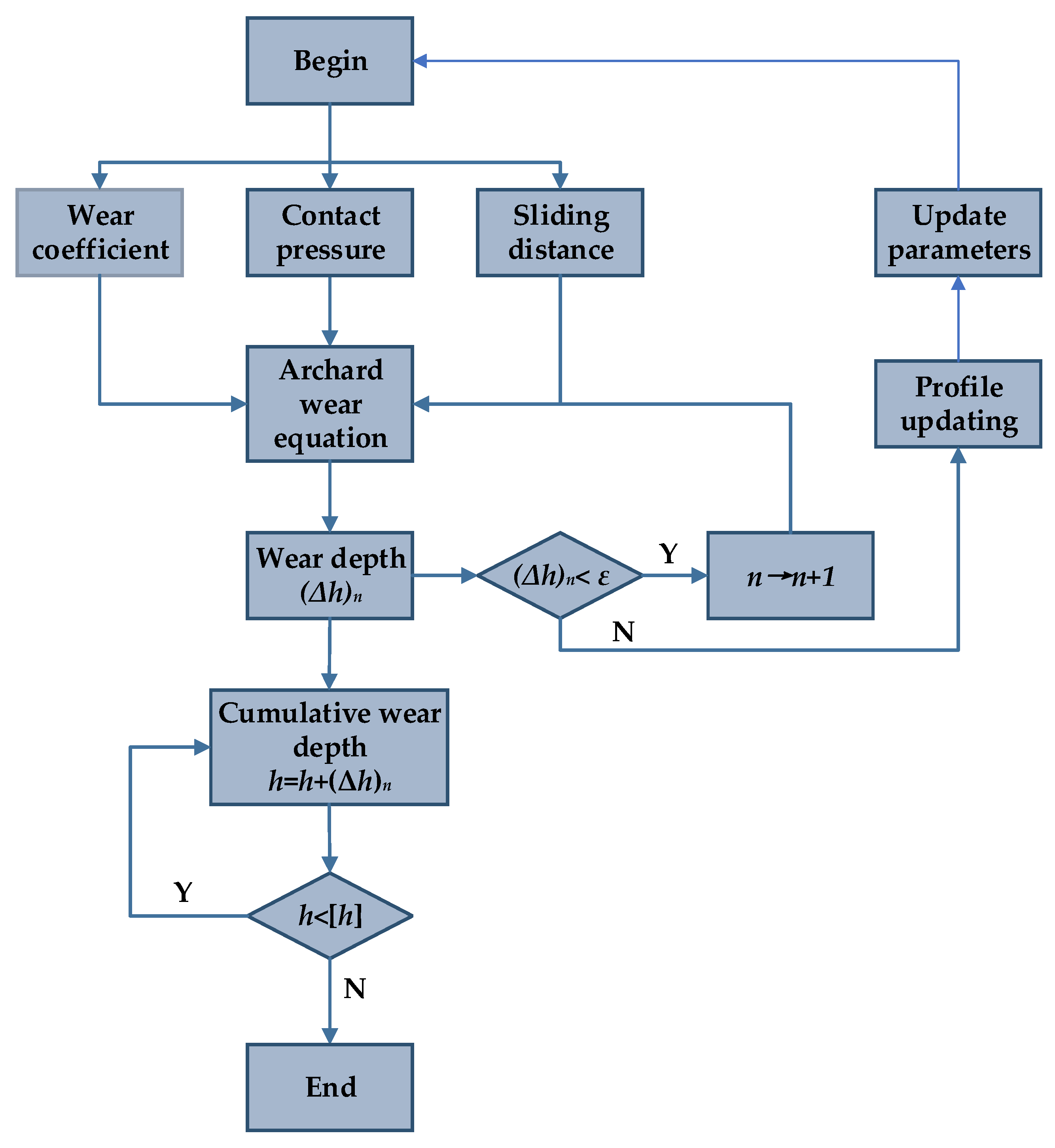
3. Numerical Simulation Model of Tooth Surface Wear

3.1. Wear Calculation Formula

Scholars generally calculate tooth surface wear depth based on the classical Archard formula, and its mathematical expression is as follows [30]:
V S = K W H
where V is the volume of wear per unit time; S is the relative sliding distance between the two meshing tooth surfaces; K is the wear coefficient; W is the normal pressure between the meshing tooth surfaces; and H is the material’s hardness.
On the basis of the “single-point observation method” and assuming that the material hardness remains constant during the tooth surface wear process, the differential expression for the dynamic wear depth at the contact point is [31]:
d h d S = K P               h = 0 S K P d S
where h is the wear depth; S is the sliding distance; K is the wear coefficient; and P is the pressure at the contact point.

3.2. Wear Coefficient

The wear coefficient is defined as the volume of wear caused by the sliding distance per unit load [32], which is affected by various factors, such as material hardness, surface roughness, and lubrication conditions, among others. Janakiraman [33] established a regression Formula (11) for the wear coefficient and the influencing parameters using a general linear regression method based on data points obtained at different loads, roughness amplitudes, and lubricant oil temperatures. In our study, the material hardness, surface roughness, and lubrication conditions used are all within the reasonable range of Janakiraman’s experimental conditions, so Formula (11) is utilized to calculate the wear coefficient of this paper:
k = 3.981 × 10 29 E L 1.29 G 7.377 R 1.589
where L is the dimensionless load; G is the dimensionless lubricant pressure viscosity coefficient; R is the dimensionless composite surface roughness; and E is the equivalent elastic modulus.
From the wear coefficient calculation formula, it can be observed that the wear coefficient increases with the increase in load and roughness and decreases with the increase in lubricant pressure viscosity coefficient. Additionally, the lubricant pressure viscosity coefficient G has the greatest influence on the wear coefficient, followed by the composite surface roughness R, while the load L has the smallest effect. The calculation formulas for each parameter are as follows:
L = W E R               G = α E               R = R q c R               R q c = R q 1 2 + R q 2 2
where W is the load per unit length; R is the equivalent radius, α is the pressure–viscosity coefficient of the lubricant; R q c is the composite roughness; and R q 1 2 and R q 2 2 are the surface roughness of the external gear and internal gear, respectively. The values of each parameter can be found in the gear design manual.

3.3. Contact Pressure

During the gear transmission process, the two meshing tooth surfaces will be subjected to contact pressure, and when using the Hertz contact theory to calculate the contact pressure, it is assumed that the contact pressure of the gear is the same in one meshing cycle, which will lead to errors in the calculation of wear depth. Given this, this paper utilizes ABAQUS 2020 finite element analysis software to obtain the contact pressure at each position within a meshing cycle and uses the measured values to calculate the wear depth in order to obtain more accurate results.

3.3.1. Establishment of High-Precision 3D Mesh Model

The high-precision three-dimensional mesh model of the internal meshing cylindrical gear pair with curved meshing lines was obtained using MATLAB 2019b engineering calculation software. We completed the initial assembly of the node meshing position of the curved meshing line internal cylindrical gear pair in MATLAB, and then imported the assembled curved meshing line internal cylindrical gear pair finite element model into ABAQUS in the form of an INP file. In ABAQUS, the meshing process of the gear pair was discretized, and the external gear was given an angular step of ±1° so that the external gear and the internal gear would rotate through the corresponding angles in sequence according to the transmission ratio until they exited the meshing.

3.3.2. Material Properties and Finite Element Analysis Steps

In the ABAQUS 2020 finite element simulation software, the material properties of the curved meshing line internal cylindrical gear pair were set: the density was set to 7800 kg/m3, the elastic modulus was 2.01 × 10⁵ MPa, and the Poisson’s ratio was 0.29. To make the initial calculation converge, we divided the analysis process into three steps:
  • Step 1: Initial Contact Analysis
In the first analysis step, we constrained all degrees of freedom of the internal and external gears, only releasing the rotational freedom of the external gear around the axis, and gave the external gear a small rotation angle to eliminate the initial clearance between the two gear tooth surfaces to ensure that the tooth surfaces could fully contact. No load was applied in this analysis step; only a stable contact relationship was established.
  • Step 2: Initial load loading
In the second analysis step, the rotational freedom of the external gear around the axis is released, and a low level of torque was applied to ensure that the initial contact analysis of the gear pair could be solved stably.
  • Step 3: Incremental loading analysis
In the third analysis step, the torque was gradually applied in the form of incremental steps until the target load was reached, completing the load contact analysis of the gear pair.

3.3.3. Solver Selection and Meshing

The implicit solver has high stability and accuracy in dealing with nonlinear problems, especially when the load is applied step by step. Gear meshing analysis involves nonlinear problems, so we used an implicit solver. The mesh type of the gear in this paper is an eight-node hexahedral linear reduced integration unit. In order to ensure the accuracy and efficiency of the calculation, we chose an appropriate number of grids. The torque and boundary conditions of the gear were applied at the reference point, and the boundary conditions were transferred to the finite element model through the rigid reference point.

3.3.4. Setting of Contact and Boundary Conditions

After the gear pair assembly, material property definition, and analysis step setup were complete, the contact and boundary conditions of the gear pair were defined. In order to simplify the calculation, the tooth surface contact of the gear pair was defined as frictionless contact. As shown in Figure 6, a finite element model of internal meshing cylindrical gears with curved meshing lines was established. The external gear tooth surface was selected as the master surface, and the internal gear tooth surface was selected as the slave surface. Fixed constraints were applied to the two side surfaces and inner holes of the internal and external gears, the freedom of the external gear to rotate around the axis was released, and a load was applied at the reference point to perform a finite element calculation of the contact pressure. The contact pressure value was extracted using the ABAQUS post-processing tool, and it was substituted into the wear formula to calculate the wear depth of the gear.

3.4. Sliding Distance

While the gears meshing with each other rotated, there was relative sliding between the two tooth surfaces, and the relative sliding distance was called the sliding distance. A larger sliding distance increases friction between gear tooth surfaces, leading to more wear and heat, which in turn affects gear life and performance. Andersson defined the sliding distance by the product of the Hertzian contact half-width and the sliding coefficient [34]:
S = 2 α H σ
According to the Hertz contact theory, the contact region of two tooth surfaces engaging with each other will change into an approximately rectangular shape under the action of stress, and the Hertz contact half-width α H can be calculated using the following formula:
α H = 4 F n ( 1 μ 1 2 E 1 ) + ( 1 μ 2 2 E 2 ) π B κ
where F n is the normal contact force on the tooth surface; B is the tooth width; and κ  is the relative curvature of the internal meshing gear, which can be expressed by the following equation based on geometric knowledge:
κ = κ 1 κ 2 κ 1 = x 1 y 1     x 1 y 1 ( x 1   +   y 1 ) 3 2               κ 2 = x 2 y 2     x 2 y 2 ( x 2   +   y 2 ) 3 2
The sliding coefficient characterizes the degree of sliding between the meshing tooth surfaces, with smaller values indicating less sliding between the tooth surfaces. With the concept of a sliding coefficient, the sliding coefficient σ i (i = 1, 2) of a pair of external and internal gears meshing with each other can be calculated by the following equation:
σ 1 = ( d S 1 d S 2 ) / d S 1 σ 2 = ( d S 2 d S 1 ) / d S 2                   d S 1 = x 1 2 + y 1 2 d y d S 2 = x 2 2 + y 2 2 d y
where x 1 , y 1 are the first-order derivatives of the x -axis and y -axis coordinate components of the external gear position vector, respectively; x 1 and y 1 are the second-order derivatives of the x -axis and y -axis coordinate components of the external gear position vector, respectively; x 2 and y 2 are the first-order derivatives of the x -axis and y -axis coordinate components of the internal gear position vector, respectively; and x 2 and y 2 are the second-order derivatives of the x -axis and y -axis coordinate components of the internal gear position vector, respectively. By substituting Equations (4) and (5) into the above equations, the relative curvature, Hertzian contact half-width, and sliding distance can be obtained.

3.5. Calculation of Wear Depth

Figure 7 illustrates the flow chart for calculating gear wear depth.
As shown in Figure 7, initially, when the tooth surface is unworn, the finite element is used to calculate the three parameters of wear coefficient K, contact pressure P, and sliding distance S. Then, the Archard wear formula is used to calculate the wear depth at any point on the tooth surface (Δh)n, and to determine whether the wear depth has reached the tooth surface reconstruction threshold. If it has not reached the threshold, the above wear calculation is repeated until the wear depth reaches the threshold. At this stage, the change in the tooth surface will have a greater impact on the contact pressure, which in turn will have a greater impact on the wear depth. Therefore, the worn finite element model should be used to determine the contact pressure and the corresponding wear depth. The above calculation steps are then repeated, and finally, the wear amounts at each stage of the tooth surface are accumulated. When the wear depth at any point on the tooth surface exceeds the maximum allowable wear [h], it can be considered that the gear has reached its wear life, and the cycle ends.
As shown in Figure 8, the tooth surface reconstruction in this paper was mainly achieved by superimposing the wear amount on the finite element mesh model to simulate the dynamic change process of tooth surface wear. By comparing the normal contact force under different wear amounts of the mesh model and combining it with data from wear-related literature, this paper uses 2.5 µm as the threshold for tooth surface reconstruction.

4. Results

The parameters in Table 1 were used to complete the tooth profile designation of the introduced novel internal gears. The novel gears and involute gears with the same tooth profile modification value at y1 = y2 = 10 µm are shown in Figure 5.
The relative curvature, sliding coefficient, sliding distance, maximum contact pressure, transmission error, and wear depth of the introduced novel gears with curved meshing lines were calculated and compared with involute gears. Moreover, the factors affecting the wear depth of gears with curved meshing lines were further studied.

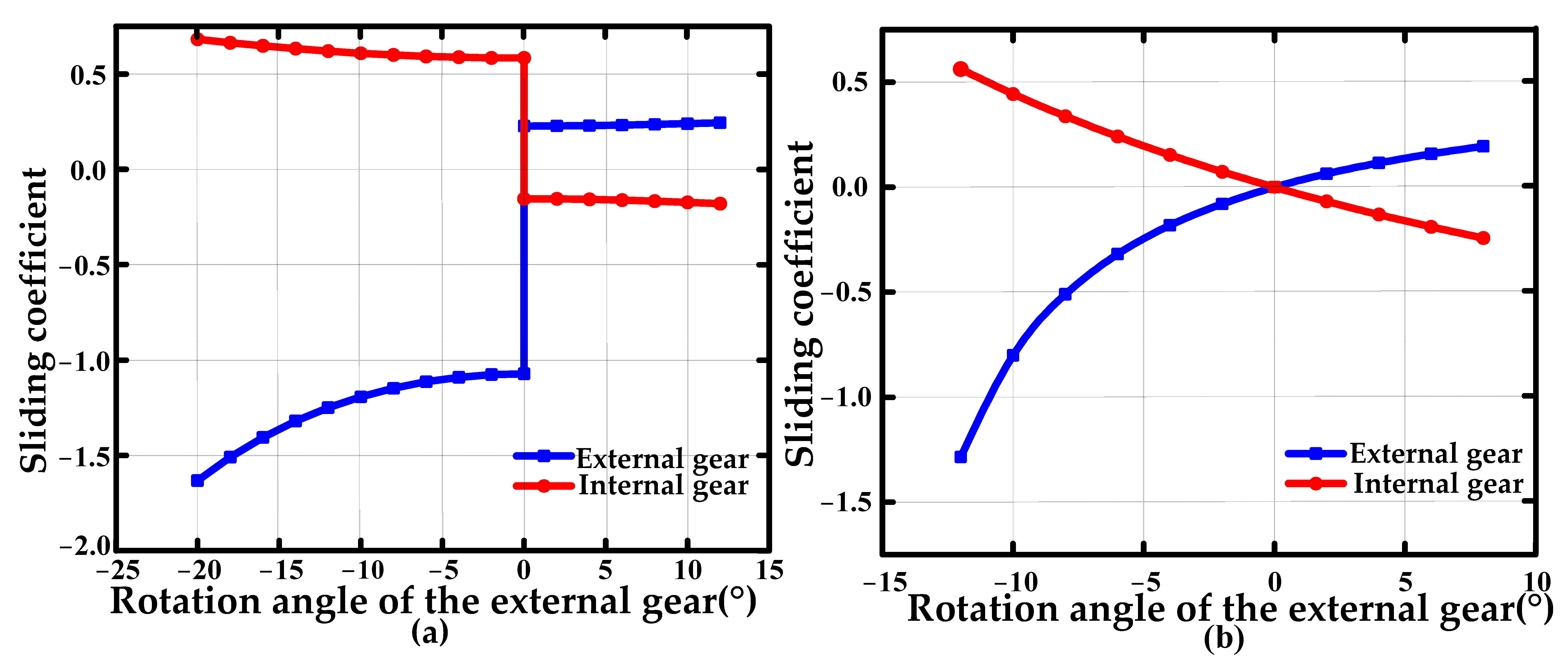
4.1. Comparison of Sliding Coefficients between Novel Gears and Involute Gears

Figure 9 illustrates the changes in the sliding coefficients of introduced novel gears and involute gears within one meshing cycle. The abscissa 0° in the figure indicates meshing at the pitch circle position. As the abscissa value increases, the corresponding gear progresses from entering mesh to exiting mesh. The two gears are purely rolling at the pitch circle position, so the sliding coefficient is zero.

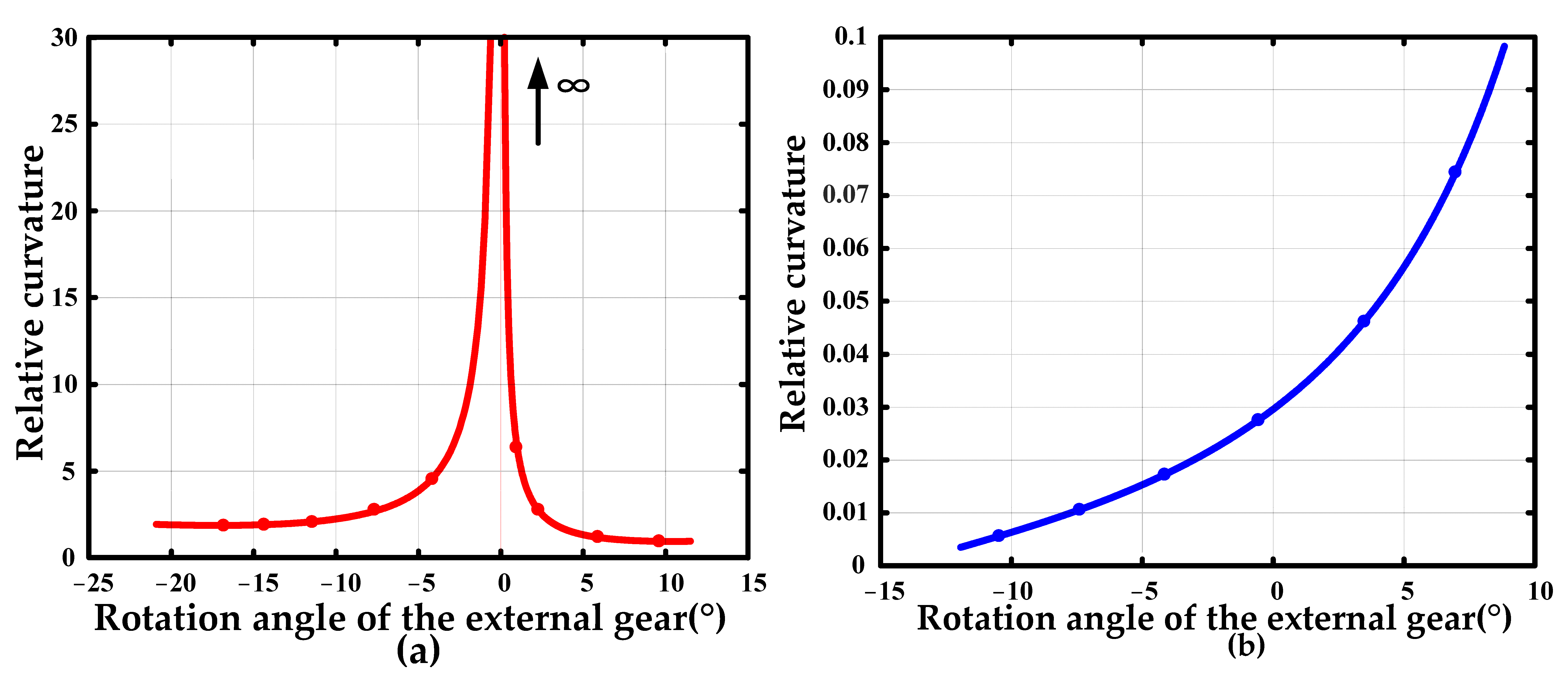
4.2. Comparison of Relative Curvature between Novel Gears and Involute Gears

Figure 10 shows the variations in relative curvature of curved meshing lines and involute internal meshing gears throughout a single meshing cycle. It can be seen that the relative curvature of the meshing gear in the curved meshing line is divided into left and right parts, with the node meshing moment as the boundary. At the nodal mesh, the pressure angle is zero, resulting in an infinite relative curvature. In addition, the relative curvature of the curved meshing line internal meshing gear is numerically larger than that of the involute internal meshing gear, which means that the former may have a smaller contact area. Considering the important influence of normal contact force at the tooth surface on sliding distance and wear depth, a more in-depth comparative analysis was carried out next.

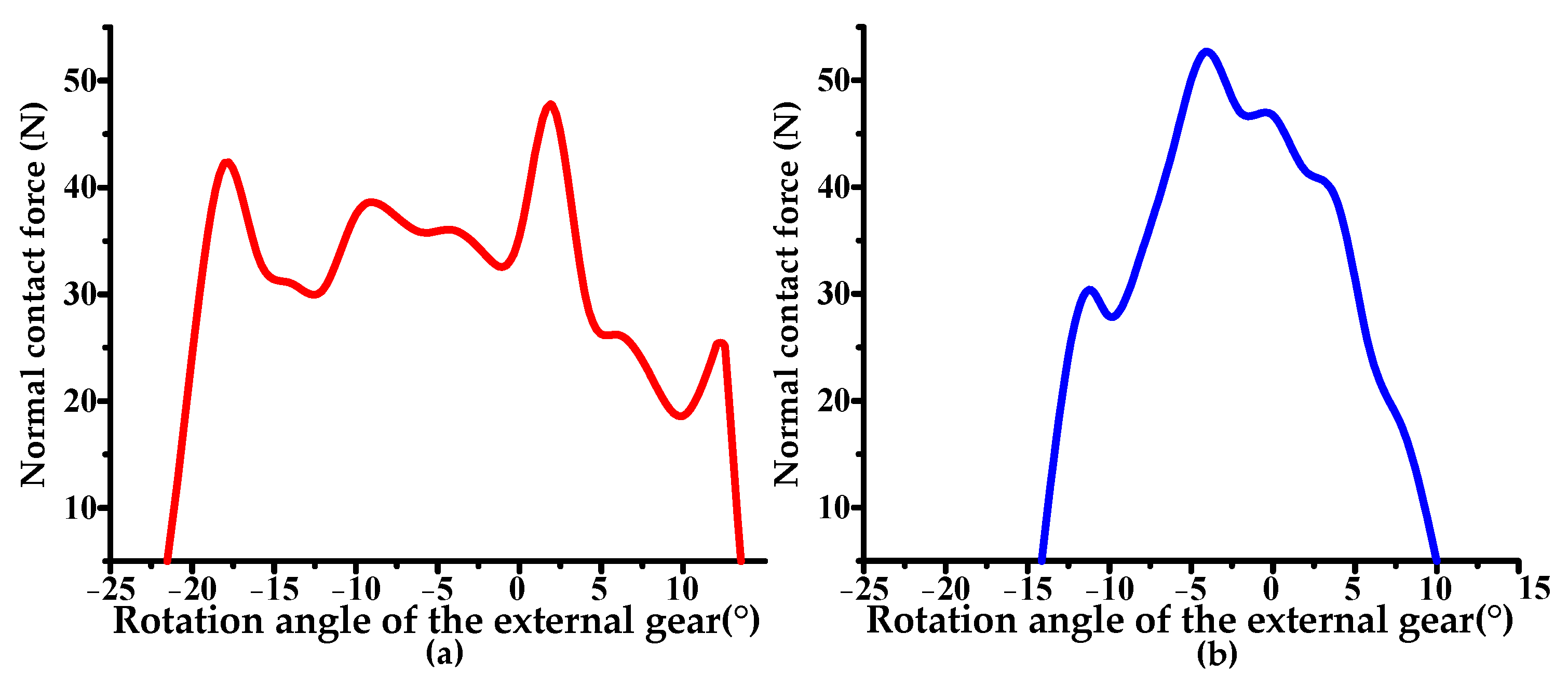
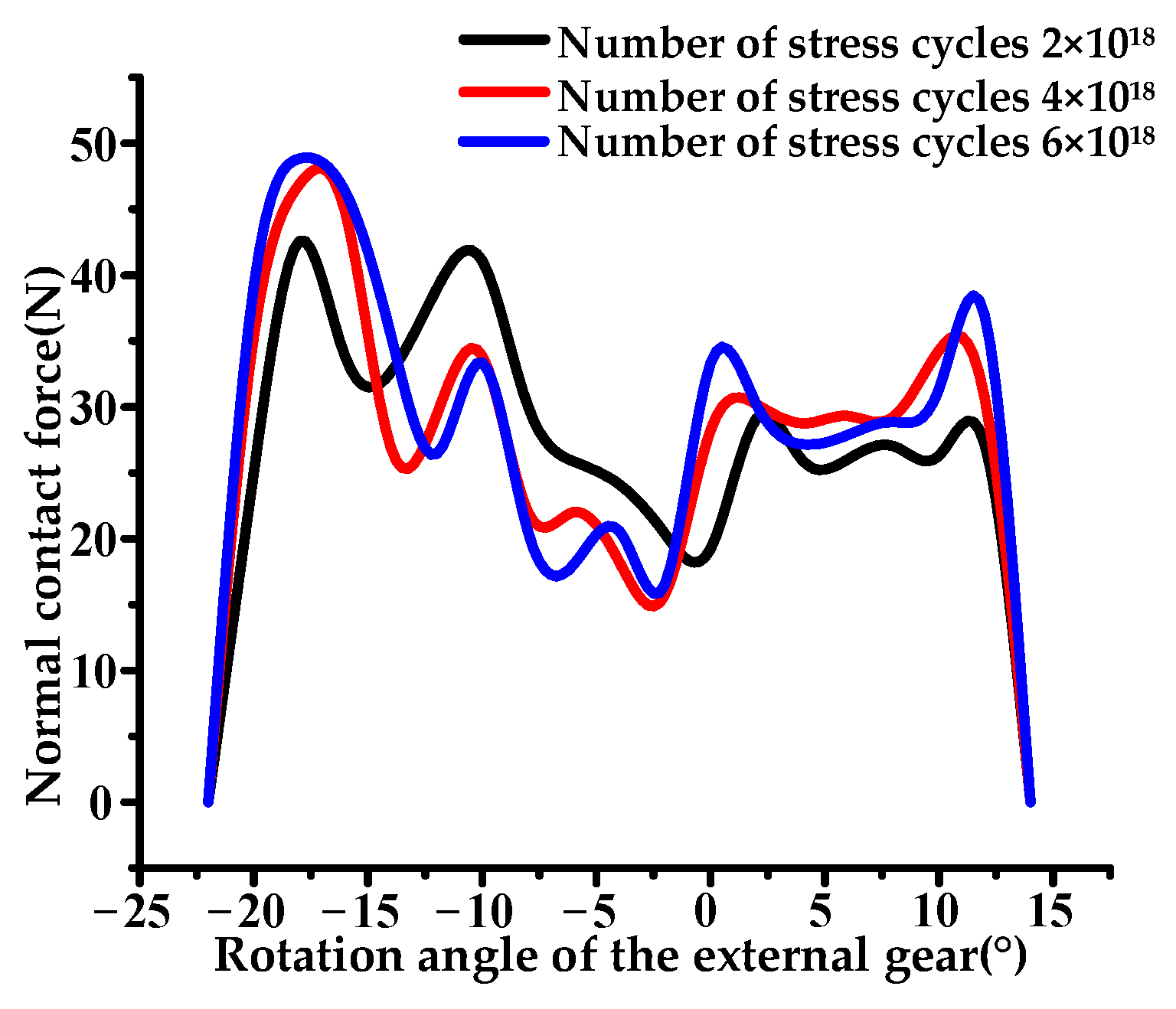
4.3. Comparison of Normal Contact Forces between Novel Gears and Involute Gears

Figure 11 depicts the changes in normal contact force within one meshing cycle of the curved meshing line and involute internal meshing gears. In the figure, the stress at each meshing moment is taken as the midpoint value of the tooth width. It can be observed that the normal contact force of the curved meshing line internal gear exhibits a trend of higher values on both sides and lower values in the middle, whereas the normal contact force of the involute internal meshing gear shows a trend of higher values in the middle and lower values on both sides. Furthermore, the maximum normal contact force of the curved meshing line internal meshing gear in one meshing cycle is smaller than the maximum normal contact force of the involute internal meshing gear, and the normal contact force distribution of the curved meshing line internal meshing gear is more uniform. As shown in Figure 12, the cloud diagram of the change of normal contact force of introduced internal novel gears and involute internal gears at node locations is given. The advantage of the introduced novel gears is further demonstrated.

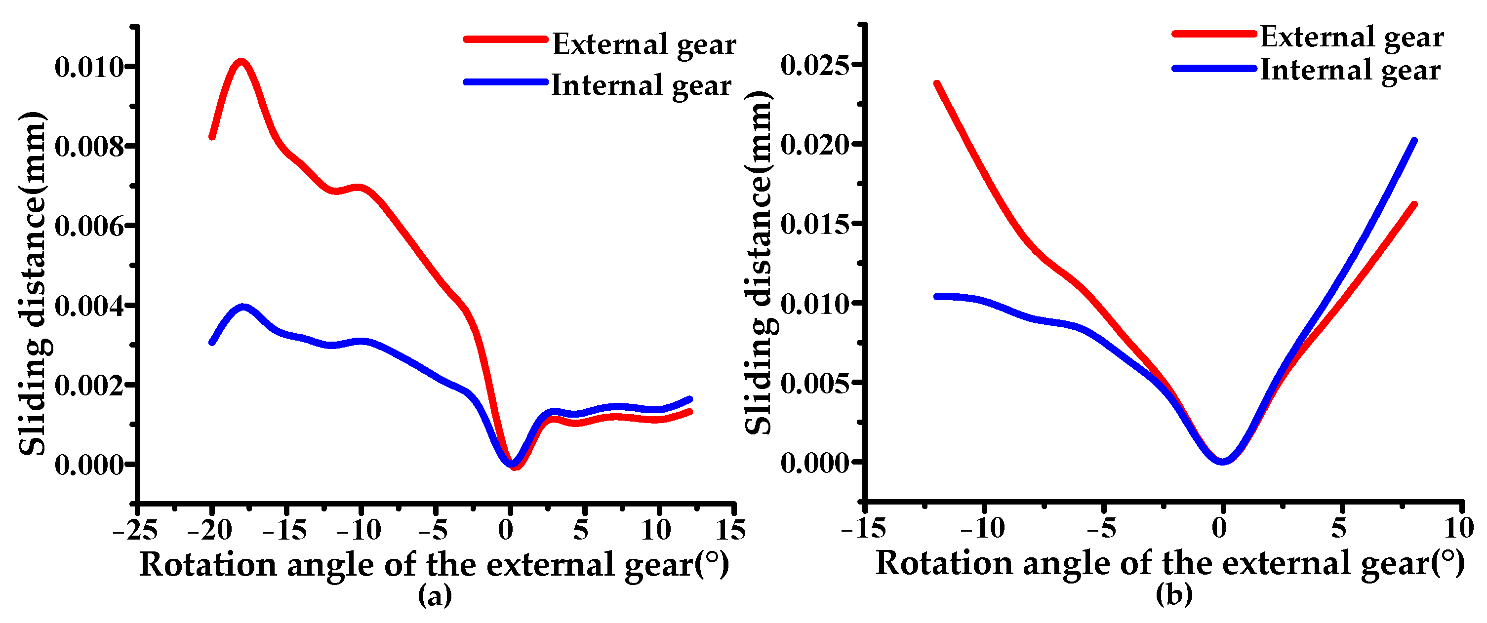
4.4. Comparison of Sliding Distance between Novel Gears and Involute Gears

Figure 13 displays the variation in sliding distance in one meshing cycle of the curved meshing line and involute internal meshing gears. It is evident from the figure that the maximum sliding distance for both gears occurred at the moment of entering mesh, whereas the minimum value was observed at the pitch circle meshing point. This can be attributed to the fact that, at the moment of entering mesh, both the sliding coefficient and normal contact force are relatively high, while the relative curvature is small, leading to a larger sliding distance. Conversely, at the pitch circle meshing point, where the sliding coefficient is zero and the gears experience minimal relative sliding, the sliding distance is at its minimum.
Taking the rotation angle 0° (pitch circle meshing point) as the boundary in the figure, the sliding distance curves of the outer gears and inner gears on both sides were compared. The sliding distance of the external gear was larger than that of the internal gear on the left side, and the sliding distance on the right side was smaller than that of the internal gear, whereas the internal gear was the opposite, which is in line with the meshing characteristics. Meanwhile, the sliding distance of the curved meshing line gear was significantly smaller than that of the involute gear, which indicates that the relative sliding of the meshing gears in the curved meshing line was smaller.

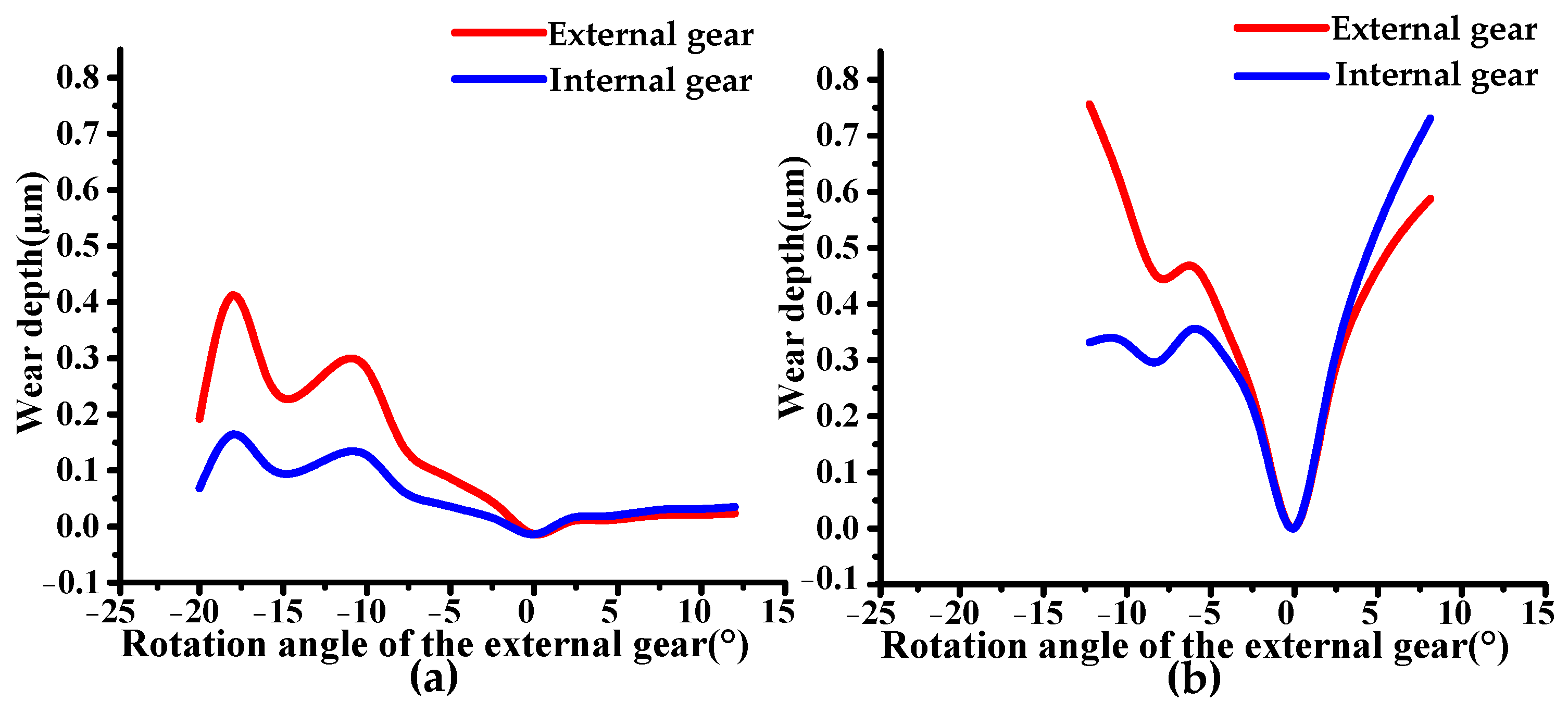
4.5. Comparison of Wear Depth between Novel Gears and Involute Gears

Figure 14a,b illustrate the change trend of the wear depth of the curved meshing line and involute internal meshing gears in one meshing cycle (the number of stress cycles was 2 × 10¹⁸). It can be observed that the variations in wear depth of both were essentially the same as the trends of their respective sliding distances. The minimum wear depth occurred at the node meshing, when the sliding distance was zero and almost no wear occurred. In contrast, the maximum wear depth occurred at the entry and exit moments of meshing, respectively. Through comparison, it was discovered that the maximum wear depth of the curved meshing line internal meshing gear was lower than that of the involute internal meshing gear, indicating that the wear of the curved meshing line internal meshing gear was lower under the same number of stress cycles, which would be beneficial to the heat dissipation of the gear transmission and the extension of its life.

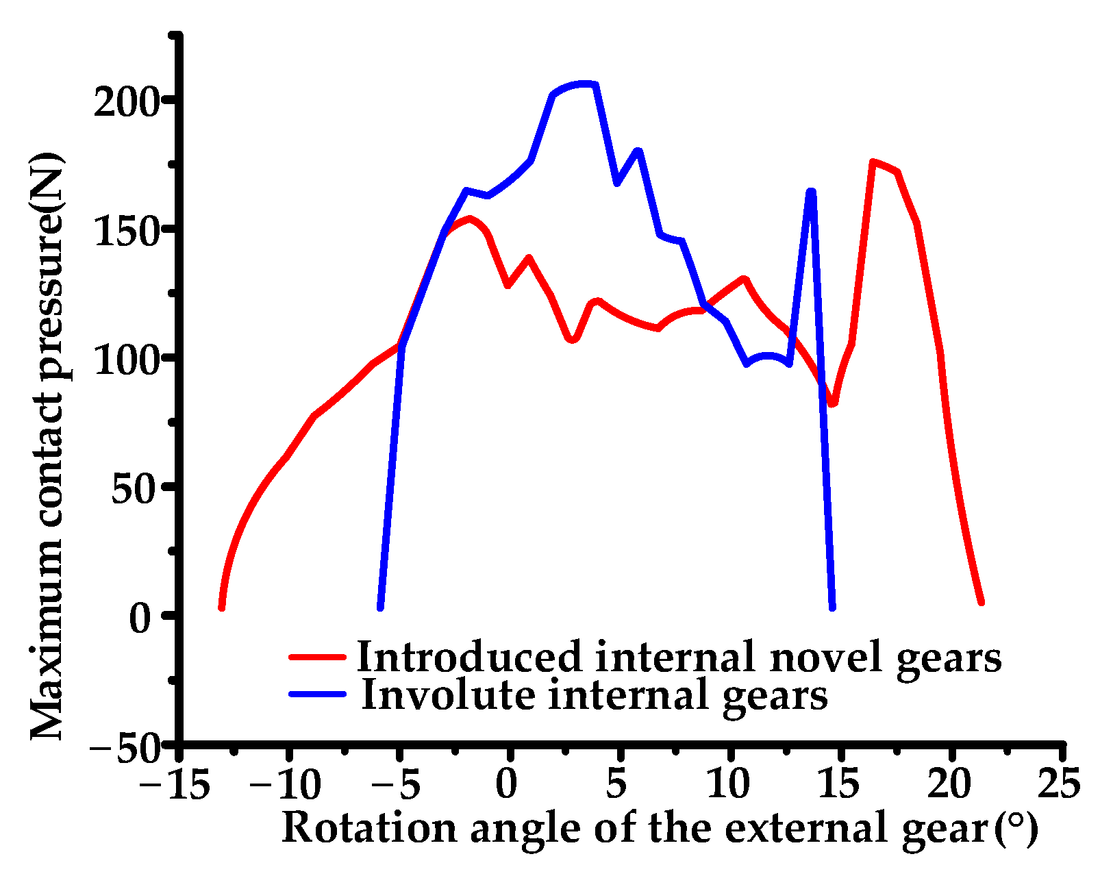
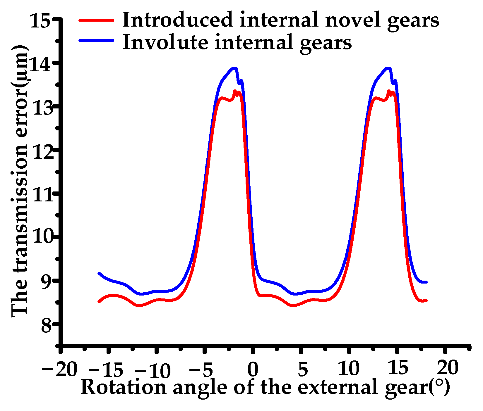
4.6. Comparison of the Maximum Contact Pressure and Transmission Error between Novel Gears and Involute Gears

Figure 15 and Figure 16 show the maximum contact pressure and transmission error of the novel gear and involute gear, respectively. The stress comparison between the novel gears and involute gears with the same tooth profile modification value at y1 = y2 = 10 µm is shown. As can be seen from the figure, under the same conditions, the maximum contact pressure and transmission error of the novel gear were smaller than those of the involute gear, reflecting that the novel gear was superior to the involute gear in terms of load-bearing characteristics and structural stability noise. Therefore, the curved meshing profile has good application potential for planetary gear trains.

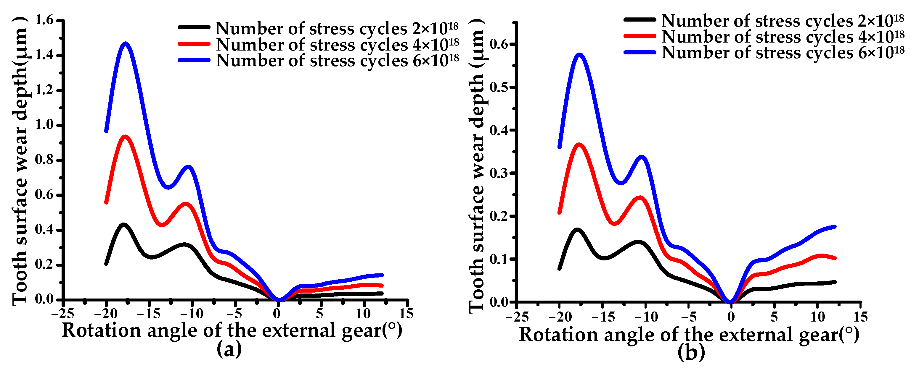
4.7. Effect of Stress Cycle Times on Wear Depth of Novel Gears

Gear wear is a dynamic process. For further study on the impact of the number of stress cycles on the wear depth, Figure 17 gives the changes in the normal contact force of the meshing gear in the curved meshing line under different numbers of stress cycles. From Figure 15, it can be seen that with the increase in the number of stress cycles, the peak normal contact force at both the entry and exit moments of the meshing increased significantly.
Figure 18 shows the change in tooth surface wear depth with the number of stress cycles. It can be seen that the wear depths of both the external gear and the internal gear continued to increase with the number of stress cycles. The change trends of the wear depth under different stress cycle numbers were basically the same. Figure 19 further demonstrates that the maximum wear depth had a non-linear increasing trend and an expanding rise rate, indicating that the wear of the meshing gears in the curved meshing line grew with the stress cycle.

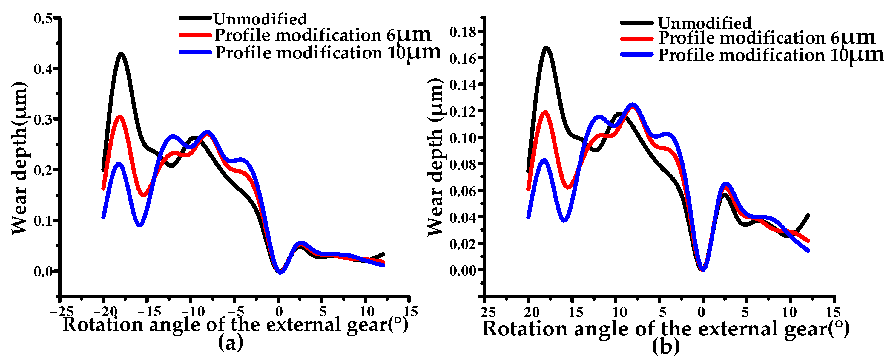
4.8. Effect of Tooth Profile Modification on Wear Depth of Novel Gears

Figure 20 and Figure 21 depict the variations in the normal contact force and wear depth of the meshing gear in the curved mesh line under various tooth profile modification amounts (the number of stress cycles was 2 × 10¹⁸). The graph shows that, without tooth profile modification, the maximum wear depth occurred at the moment when the gear entered meshing. At this time, the normal contact force was also a peak value during the meshing process, and tooth profile modification could significantly reduce the normal contact force when engaging, thus reducing the maximum wear depth, but also increasing normal contact force when exiting engagement. Therefore, appropriate tooth profile modification could reduce the maximum wear depth in one meshing cycle without increasing the wear depth too much at other meshing times, thereby achieving uniform tooth surface wear.

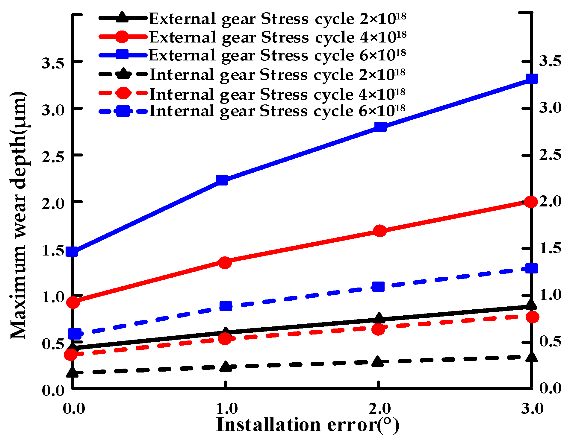
4.9. Effect of Installation Error on Wear Depth of Novel Gears

Figure 22 indicates the variation in the maximum wear depth of the meshing gear in the curved meshing line with the installation error and the number of stress cycles. The chart shows that installation errors had a considerable impact on the maximum wear depth. As the installation error increased, the maximum wear depth of the curved meshing line external gear and internal gear also increased. In addition, as the number of stress cycles increased, the maximum wear depth also increased, which indicates that the impact of the installation error on the maximum wear depth expanded with the wear process. It can be seen that installation errors increased gear wear, and this unfavorable effect was more significant especially with high-turnover operation, which was detrimental to gearing. Therefore, the installation error should be minimized to improve the reliability and life of the gear transmission.

5. Conclusions

In this paper, an internal meshing cylindrical gears with a curved meshing line was designed, and its tooth contact and wear characteristics were deeply studied. The advantages of the introduced novel gears in wear resistance are demonstrated based on simulation results. From the present study, the following conclusions are drawn.
(1) The sliding coefficients of the introduced novel gears with curved meshing lines were similar to that of the involute gears; the relative curvature was greater than that of the involute gears; and the normal contact force was lower than that of the involute gears because the contact ratio of the introduced gears was larger than that of involute gears.
(2) Under the same running times, the sliding distance and wear depth of the inner gear and the outer gear of the curved meshing line were smaller than those of the involute gears. The reduction in wear was beneficial, increasing the effective running life of the gear pair.
(3) The peak wear depth of the introduced novel gears occurred at the moment when the gear entered and exited the meshing, at which time the contact stress was higher, so the wear depth was greater. When meshing at the pitch circle, there was almost no relative sliding between the two tooth surfaces, so there was almost no wear.
(4) The peak value of wear depth could be reduced by tooth modification because the load distribution of tooth surface was improved via tooth modification. The installation errors increased the peak wear depth because the installation errors worsened the load distribution and exacerbated the stress concentration of the tooth surface.

Author Contributions

Conceptualization, C.J.; Methodology, C.J.; Software, G.Z.; Validation, G.Z.; Data curation, G.L.; Writing—original draft, G.Z. All authors have read and agreed to the published version of the manuscript.

Funding

The work described in this paper was supported by the National Natural Science Foundation of China (Grant Nos. 52375044 and 52005107) and the Fujian Provincial Science and Technology Major Special Projects (Grant No. 2021HZ024006).

Data Availability Statement

The original contributions presented in the study are included in the article, further inquiries can be directed to the corresponding author.

Conflicts of Interest

The authors declare no conflicts of interest.

Appendix A

Notation
u t the meshing line parameter
r 1 the external gear pitch radius
rthe sun gear pitch radius
S i coordinate system (i = 1, 2, f)
O i coordinate origin (i = 1, 2, f)
r i tooth profile equation (i = 1, 2)
ϕ i rotation angle of pinion and gear (i = 1, 2)
m 12 gear transmission ratio
N i tooth number of pinion and gear (i = 1, 2)
σ i the sliding coefficient (i = 1, 2)
α H the Hertz contact half-width
F n the normal contact force on the tooth surface
B the tooth width
κ the relative curvature of the internal meshing gear
x i the first-order derivatives of the x -axis (i = 1, 2)
y i the first-order derivatives of the y -axis (i = 1, 2)
x i the second-order derivatives of the x -axis (i = 1, 2)
y i the second-order derivatives of the y -axis (i = 1, 2)

References

  1. Jia, C.; Zhang, G. Investigation on the Dynamic Characteristics of Non-Orthogonal Helical Face Gears with Higher-Order Tooth Surface Modification. Mathematics 2024, 12, 366. [Google Scholar] [CrossRef]
  2. Rai, P.; Barman, A.G. An approach for design optimization of helical gear pair with balanced specific sliding and modified tooth profile. Struct. Multidiscip. Optim. 2019, 60, 331–341. [Google Scholar] [CrossRef]
  3. Chen, Z.; Ji, P. Research on the variation of mesh stiffness and transmission error for spur gear with tooth profile modification and wear fault. Eng. Fail. Anal. 2021, 122, 105184. [Google Scholar] [CrossRef]
  4. Sánchez, M.B.; Pleguezuelos, M.; Pedrero, J.I. Influence of profile modifications on meshing stiffness, load sharing, and trasnsmission error of involute spur gears. Mech. Mach. Theory 2019, 139, 506–525. [Google Scholar] [CrossRef]
  5. Pleguezuelos, M.; Pedrero, J.I.; Sánchez, M.B.; Vicente, E. Influence of wear on load sharing and transmission error of spur gears with profile modifications. In Proceedings of the International Conference on Machine and Industrial Design in Mechanical Engineering, Novi Sad, Serbia, 10–12 June 2021; Springer International Publishing: Cham, Switzerland, 2021; pp. 111–119. [Google Scholar]
  6. Tunalioglu, M.S.; Tuc, B. Effect of tooth profile modification on wear in internal gears. Proc. IOP Conf. Ser. Mater. Sci. Eng. 2018, 351, 012003. [Google Scholar] [CrossRef]
  7. Gołębski, R.; Ivandić, Ž. Analysis of modification of spur gear profile. Teh. Vjesn. 2018, 25, 643–648. [Google Scholar]
  8. Narazaki, J.; Ikejo, K.; Nagamura, K.; Tanaka, E.; Seyama, N. Effect of Tooth Profile Modification on Tooth Wear of Involute Spur Gear. In Proceedings of the JSME International Conference on Motion and Power Transmissions 2017, Kyoto, Japan, 28 February–3 March 2017; The Japan Society of Mechanical Engineers: Sapporo, Japan, 2017; p. 05-05. [Google Scholar]
  9. Abdul, W.A.M.; Krantz, T.L.; Shareef, I. Influence of tip modification on performance characteristics of involute spur gears. Aust. J. Mech. Eng. 2018, 18, 395–414. [Google Scholar] [CrossRef]
  10. Li, X.; Yang, H.; Niu, W.; Guo, R.; Sun, L. Investigation on tooth surface wear of cycloid drives considering tooth profile modifications. Lubricants 2023, 11, 323. [Google Scholar] [CrossRef]
  11. Zhang, X.; Fang, Z.; Yin, X.; Jia, H.; Ma, Y.; Xu, Y.; Zhao, H. Transform of parameter and teeth surface modification for non-standard planetary spur gear train with X-gears. Proc. Inst. Mech. Eng. Part K J. Multi-Body Dyn. 2023, 237, 279–289. [Google Scholar] [CrossRef]
  12. Issayeva, I.; Povetkin, V.; Alpeisov, A.; Bukayeva, A.; Arinova, D. An Increase of the Loading Capacity and Reliability of Gears by Methods of Optimizing Involute Gearing Parameters. East.-Eur. J. Enterp. Technol. 2020, 1, 103. [Google Scholar] [CrossRef]
  13. Zhang, J.; Liu, X. Effects of misalignment on surface wear of spur gears. Proc. Inst. Mech. Eng. Part J J. Eng. Tribol. 2015, 229, 1145–1158. [Google Scholar] [CrossRef]
  14. Park, C.I. Influence of tooth profile and surface roughness on wear of spur gears considering temperature. J. Mech. Sci. Technol. 2023, 37, 5297–5306. [Google Scholar] [CrossRef]
  15. Chernets, M.V.; Shil’ko, S.V.; Starzhinsky, V.E. Estimation of Bearing Capacity and Wear Resistance of Spur Gear Meshing Taking into Account Tooth Profile Correction and Sliding Friction Coefficient. In New Approaches to Gear Design and Production 2020; Springer: Berlin/Heidelberg, Germany, 2020; pp. 261–272. [Google Scholar]
  16. De, T.; Lizhuang, T.; Yue, H.; Bei, L. Dynamics of wind turbine gear wear fault based on tooth profile modification and friction coupling. Acta Energiae Solaris Sin. 2022, 43, 260. [Google Scholar]
  17. Chen, W.; Lei, Y.; Fu, Y.; Hou, L. A study of effects of tooth surface wear on time-varying mesh stiffness of external spur gear considering wear evolution process. Mech. Mach. Theory 2021, 155, 104055. [Google Scholar] [CrossRef]
  18. Zhang, S.; Sun, Z.; Guo, F. Investigation on wear and contact fatigue of involute modified gears under minimum quantity lubrication. Wear 2021, 484, 204043. [Google Scholar] [CrossRef]
  19. Feng, K.; Smith, W.A.; Randall, R.B.; Wu, H.; Peng, Z. Vibration-based monitoring and prediction of surface profile change and pitting density in a spur gear wear process. Mech. Syst. Signal Process. 2022, 165, 108319. [Google Scholar] [CrossRef]
  20. Zhang, Z.; Zheng, C.; Wen, M.; Yang, S.; Li, H.; Du, Q. A Wear Prediction Model for Spur Gears Based on the Dynamic Meshing Force and Tooth Profile Reconstruction. In Proceedings of the 2nd International Conference on Computer Engineering, Information Science & Application Technology (ICCIA 2017), Wuhan, China, 8–9 July 2017; Atlantis Press: Amsterdam, The Netherlands, 2016; pp. 851–860. [Google Scholar]
  21. Chernets, M.; Kiełbiński, J.; Chernets, J. A study on the impact of teeth meshing conditions and profile correction on the carrying capacity, wear, and life of a cylindrical gear. Tribologia 2016, 266, 25–43. [Google Scholar] [CrossRef]
  22. Sekar, R.P. Reduction of tooth wear on asymmetric spur gear through profile correction factors. Aust. J. Mech. Eng. 2022, 22, 506–522. [Google Scholar] [CrossRef]
  23. Sánchez, M.B.; Pleguezuelos, M.; Pedrero, J.I. Influence of profile modification on the transmission error of spur gears under surface wear. Mech. Mach. Theory 2024, 191, 105473. [Google Scholar] [CrossRef]
  24. Xiao, Z.; Shi, X.; Wang, X.; Ma, X.; Han, Y. Lubrication analysis and wear mechanism of heavily loaded herringbone gears with profile modifications in full film and mixed lubrication point contacts. Wear 2021, 477, 203790. [Google Scholar] [CrossRef]
  25. Huangfu, Y.; Zhao, Z.; Ma, H.; Han, H.; Chen, K. Effects of tooth modifications on the dynamic characteristics of thin-rimmed gears under surface wear. Mech. Mach. Theory 2020, 150, 103870. [Google Scholar] [CrossRef]
  26. Zheng, F.; Zhang, J.; Yao, L.; Tan, R. Investigation on the wear of spur gears generated by modified cutter. Friction 2021, 9, 288–300. [Google Scholar] [CrossRef]
  27. Mu, Y.; Li, W.; Fang, Z. Tooth surface modification method of face-milling spiral bevel gears with high contact ratio based on cutter blade profile correction. Int. J. Adv. Manuf. Technol. 2020, 106, 3229–3237. [Google Scholar] [CrossRef]
  28. Karpuschewski, B.; Beutner, M.; Köchig, M.; Härtling, C. Influence of the tool profile on the wear behaviour in gear hobbing. CIRP J. Manuf. Sci. Technol. 2017, 18, 128–134. [Google Scholar] [CrossRef]
  29. Jia, C.; He, Q.; Xiao, J.; Dong, H. Design and Analysis of Novel Non-Involute Cylindrical Gears with a Curved Path of Contact. Mathematics 2022, 10, 4290. [Google Scholar] [CrossRef]
  30. Shen, Z.; Qiao, B.; Yang, L.; Luo, W.; Yang, Z.; Chen, X. Fault mechanism and dynamic modeling of planetary gear with gear wear. Mech. Mach. Theory 2021, 155, 104098. [Google Scholar] [CrossRef]
  31. Sun, Y.; Li, Y.; Zhang, Q.; Qin, X.; Chen, K. Wear analysis and simulation of small module gear based on Archard model. Eng. Fail. Anal. 2023, 144, 106990. [Google Scholar] [CrossRef]
  32. Guan, Y.; Chen, J.; Fang, Z.; Hu, S. A quick multi-step discretization and parallelization wear simulation model for crown gear coupling with misalignment angle. Mech. Mach. Theory 2022, 168, 104576. [Google Scholar] [CrossRef]
  33. Kahraman, A.; Li, S.; Janakiraman, V. An Investigation of the Impacts of Contact Parameters on Wear Coefficient. J. Tribol. 2014, 136, 031602-1–031602-7. [Google Scholar]
  34. Andersson, S. Initial wear of gears. Tribol. Int. 1977, 10, 206–210. [Google Scholar] [CrossRef]
Figure 1. Schematic diagram of planetary gear train meshing line.
Applsci 14 05399 g001
Figure 2. Internal gear mesh line construction.
Applsci 14 05399 g002
Figure 3. Coordinate system of the internal meshing gears.
Applsci 14 05399 g003
Figure 4. Unmodified tooth surface.
Applsci 14 05399 g004
Figure 5. Tooth profile modification.
Applsci 14 05399 g005
Figure 6. Finite element modeling of curved meshing line internal meshing cylindrical gear.
Applsci 14 05399 g006
Figure 7. Flow chart for calculation of gear wear depth.
Applsci 14 05399 g007
Figure 8. Finite element mesh model tooth surface reconstruction.
Applsci 14 05399 g008
Figure 9. Comparison of sliding coefficients: (a) introduced novel internal gears; (b) involute internal gears.
Applsci 14 05399 g009
Figure 10. Comparison of relative curvatures: (a) introduced internal novel gears; (b) involute internal gears.
Applsci 14 05399 g010
Figure 11. Comparison of normal contact forces: (a) introduced internal novel gears; (b) involute internal gears.
Applsci 14 05399 g011
Figure 12. Normal contact force distribution at node locations: (a) introduced internal novel gears; (b) involute internal gears.
Applsci 14 05399 g012
Figure 13. Comparison of sliding distances: (a) introduced internal novel gears; (b) involute internal gears.
Applsci 14 05399 g013
Figure 14. Comparison of wear depth: (a) introduced internal novel gears; (b) involute internal gears.
Applsci 14 05399 g014
Figure 15. Comparison of maximum contact pressure.
Applsci 14 05399 g015
Figure 16. Comparison of the transmission error.
Applsci 14 05399 g016
Figure 17. Comparison of normal contact forces of introduced novel gears under different stress cycle times.
Applsci 14 05399 g017
Figure 18. Tooth surface wear depth of introduced novel gear pair under different stress cycles: (a) external gear; (b) internal gear.
Applsci 14 05399 g018
Figure 19. Variation in tooth surface wear depth of introduced novel gear pair with stress cycle times.
Applsci 14 05399 g019
Figure 20. Comparison of normal contact force of introduced novel gears with different profile modifications.
Applsci 14 05399 g020
Figure 21. Tooth surface wear depth of introduced novel gears with different tooth modification amounts: (a) external gear; (b) internal gear.
Applsci 14 05399 g021
Figure 22. Variation in maximum wear depth of introduced novel gears with installation errors and stress cycles.
Applsci 14 05399 g022
Table 1. Design parameters of internal gears.
Design ParameterNovel GearsInvolute Gears
Tooth number29/7929/79
Normal module (mm)2.252.25
Helix angle (degree)00
Face width (mm)2525
Addendum coefficient11
Dedendum coefficient1.251.25
Root radius (mm)0.10.1
Contact ratio2.821.69
k10.32/
k20.32/
Torque (N·m)134134
Disclaimer/Publisher’s Note: The statements, opinions and data contained in all publications are solely those of the individual author(s) and contributor(s) and not of MDPI and/or the editor(s). MDPI and/or the editor(s) disclaim responsibility for any injury to people or property resulting from any ideas, methods, instructions or products referred to in the content.

