Article

Low-Carbon Operation Strategy of Park-Level Integrated Energy System with Firefly Algorithm

by
Hongyin Chen
1,2,
Songcen Wang
1,2,
Yaoxian Yu
1,2,*,
Yi Guo
1,2,
Lu Jin
1,2,
Xiaoqiang Jia
1,2,
Kaicheng Liu
1,2 and
Xinhe Zhang
1,2
1
National Key Laboratory of Power Grid Safety, Beijing 100192, China
2
China Electric Power Research Institute, Beijing 100192, China
*
Author to whom correspondence should be addressed.
Appl. Sci. 2024, 14(13), 5433; https://doi.org/10.3390/app14135433
Submission received: 28 March 2024 / Revised: 12 June 2024 / Accepted: 14 June 2024 / Published: 22 June 2024

Abstract

:
The integrated energy system at the park level, renowned for its diverse energy complementarity and environmentally friendly attributes, serves as a crucial platform for incorporating novel energy consumption methods. Nevertheless, distributed energy generation, characterized by randomness, fluctuations, and intermittency, is significantly influenced by the surrounding environment. Within the park, the output of multiple devices frequently diverges significantly from the actual demand, potentially resulting in energy waste phenomena, such as the curtailment of wind and solar power. To tackle the dual challenges of balancing energy supply and demand while reducing carbon emissions in the industrial park, this paper introduces a low-carbon integrated energy system that incorporates distributed renewable and clean energy sources. Mathematical models are formulated for the source–grid–load–storage components of this low-carbon integrated energy system. Furthermore, various operational scenarios for the park-level integrated energy system are analyzed. The ultimate goal is to devise an economically viable, low-carbon, and efficient operational strategy for the integrated energy system, aiming to satisfy the diverse objectives of various stakeholders.

1. Introduction

As China actively and prudently advances towards carbon peak and carbon neutrality, expediting the planning and construction of a new energy system has become increasingly crucial in the field of energy dynamics [1,2,3]. Nationwide efforts are underway to vigorously promote the development of photovoltaic (PV) power, wind power, and other low-carbon renewable energy sources, further optimizing the energy structure. The integrated energy system at the park level stands as a pivotal avenue for navigating the transition of energy systems amidst the backdrop of carbon neutrality [4]. Through the implementation of efficient optimization and operational control strategies, it elevates the overall operational efficiency of the park. This underscores a critical direction in the research and development of low-carbon energy systems at the park level. The park-level low-carbon integrated energy, consisting of distributed energy sources, represents the optimal solution for addressing the dual pressures of energy and the environment [5]. Horizontally, it features a diverse mix of complementary energy sources, while vertically, it promotes friendly interaction and coordinated optimization among sources, grids, loads, and storage, thereby enhancing the economic efficiency of energy supply and utilization [6]. The development and application of biomass, heat pump, and distributed natural gas tri-generation technologies have promoted the advancement of integrated multi-energy solutions at the user end, encompassing cooling, heating, electricity, and gas. A regional integrated energy system, composed of various intermittent, fluctuating energy sources, and time-varying flexible loads, requires comprehensive consideration of technical, stability, economic, energy efficiency, and environmental factors during its planning, construction, and operation. These indicators are interrelated and often conflicting, making the coordination and optimization of operations a focal point of research.
Currently, numerous scholars have conducted research on the planning, design, and optimized operation of park-level integrated energy systems [7,8]. Scholars have investigated user-side demand response for thermal and electrical loads, establishing an optimized operational model. Building upon the physical and mathematical foundations of the model, they have researched optimized operational control strategies to enhance the security and stability of low-carbon energy systems within the park. At the planning level, scholars are engaged in the study of the site selection, capacity planning, design, and coupled operation of low-carbon integrated energy systems [9]. In terms of operational efficiency, the focus is on research related to the control strategies for the integrated optimization of low-carbon comprehensive energy with multiple complementary sources. In the realm of energy management, scholars intricately consider the stochastic and intermittent nature of variables like wind and solar energy storage [10]. By incorporating the characteristics of demand-side response, they apply advanced algorithms such as particle swarm optimization and differential evolution. This effort leads to the establishment of stochastic optimization models for the economic operation of regional low-carbon integrated energy systems and a versatile bus-based model [11]. By employing various mathematical models and economic analysis tools, the economic viability of low-carbon integrated energy systems is investigated. This includes an analysis of the energy efficiency variations in combined cooling, heating, and power (CCHP) systems under different operational modes. Environmental factors are also integral to the study of low-carbon integrated energy, wherein pollution gas emission penalty functions are incorporated into the objective function, establishing an economic dispatch model for low-carbon integrated energy systems [12]. With the deepening application of emerging technologies such as cloud computing, big data, the Internet of Things, and blockchain in the energy industry, the large-scale deployment and coordinated control of renewable energy, energy storage, and distributed applications of flexible loads have become key research priorities in the planning, construction, and operational management of regional energy systems. In a park-level low-carbon integrated energy system, multiple components such as generation, grid, load, and storage are involved [13]. Its operation involves various factors, including technical, economic, energy conservation, environmental protection, and energy efficiency. It is necessary to establish a comprehensive energy system cooperative optimization control model based on the analysis and research of the characteristics of each component, i.e., generation, grid, load, and storage. This model aims to meet the optimization operational requirements in real-world scenarios [14]. The regional integrated energy system faces challenges in balancing the technical, environmental, reliability, and electrical quality objectives, with inherent correlations and contradictions among them [15]. Effectively coordinating these diverse goals remains a pivotal challenge in the field, aiming to optimize the system to the greatest extent across objectives.
Current research predominantly focuses on singular aspects of low-carbon integrated energy systems in industrial parks, lacking comprehensive analyses of the entire system operation. This article constructs a low-carbon integrated energy system composed of distributed renewable energy and clean energy and establishes mathematical models for the source, grid, load, and storage components of the low-carbon integrated energy system in the industrial park. The study analyzes operational strategies for the park-level integrated energy system under various scenarios, aiming to design an economically, low-carbon, and efficient mode of operation for the integrated energy system to meet the objectives of diverse stakeholders.

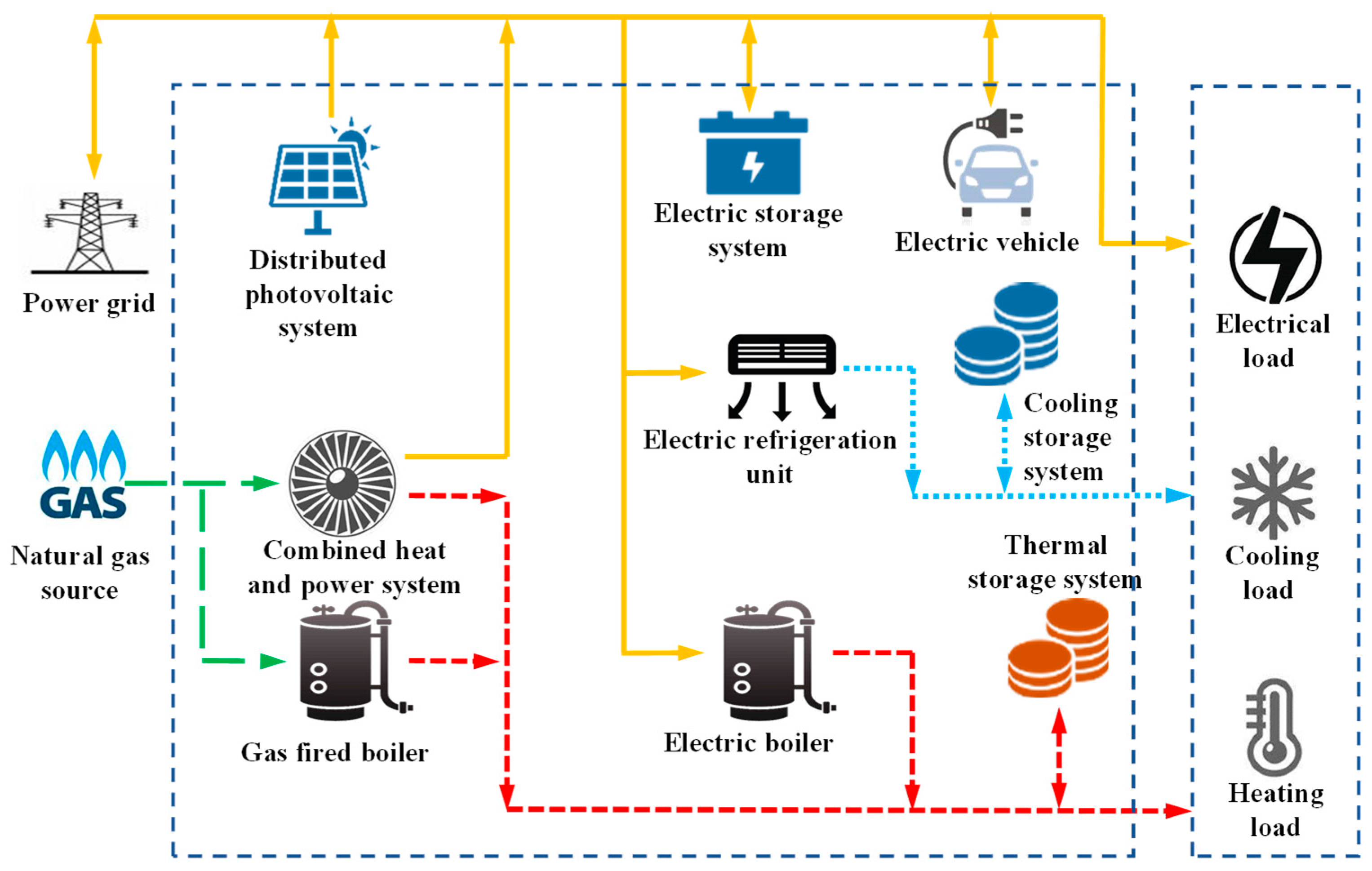
2. Low-Carbon Integrated Energy System Architecture

The low-carbon integrated energy system represents the future direction for comprehensive energy utilization in industrial parks and has garnered increasing attention and application in the construction of modern energy systems. Comprising energy input, conversion, storage, and utilization components, the low-carbon integrated energy system illustrated in Figure 1 is applicable to industrial parks. The energy input side includes the power grid supply, power plants, solar energy, and natural gas, while the output side serves users with electricity, cooling, and heating.
As illustrated in Figure 1, the power supply of the grid primarily relies on power plants. PV power generation converts solar energy into electricity, while micro gas turbines and gas boilers generate electricity and heat through the combustion of natural gas. Both electrical and thermal energy storage play a crucial role in mitigating fluctuations and smoothing peak demands, addressing load variability issues. These storage systems facilitate the rational distribution of various input energies to the output side, and energies should comply with the power balance equation.

3. Mathematical Model of Low-Carbon Integrated Energy Systems

3.1. Mathematical Model of PV Power Generation

Distributed PV power generation is significantly influenced by environmental factors, and, ideally, its output power is determined by both the illuminance and ambient temperature. The calculation formula is expressed as follows:
P P V = f p v P P V R G G S 1 + α P V T T S
In this equation, PPV represents the output power of PV generation, kW; f p v and PPVR respectively denote the derating factor and rated output power of the PV generation equipment under standard conditions, kW; G and GS respectively represent the illumination intensity at the current location of the PV generation equipment and the illumination intensity under standard conditions, W/m2; α P V is the power temperature coefficient under standard conditions, 1/K; and T and TS respectively represent the temperatures on the surface of the PV panel and the temperature on the surface of the PV panel under standard conditions, K.

3.2. Mathematical Model of Micro Gas Turbines

Micro gas turbines utilize the combustion of natural gas to drive the rotation of generator blades, generating electrical energy. Simultaneously, inevitably, thermal energy is produced. The collection of this thermal energy for heating purposes can enhance the overall energy efficiency of the gas turbine system. In an ideal scenario, the thermal and electrical power output of a gas turbine is directly proportional to the consumption rate of natural gas, as expressed by the following formula:
P E G T = η E F G T
P H G T = η H F G T
η E + η H + η l o s s = 1
In this equation, PEGT and PHGT represent the electrical power and thermal power generated by the micro gas turbine, respectively, kW. η E , η H , and η l o s s denote the electrical efficiency, thermal efficiency, and thermal loss rate of the gas turbine, while FGT represents the combustion rate of natural gas, KW.

3.3. Mathematical Model of Gas Boilers

Gas boilers, like micro gas turbines, consume natural gas, but gas boilers only generate thermal power and not electrical power. When the user’s heat load is substantial and cannot be met solely by a gas turbine, gas boilers can be activated to achieve power balance on both sides of the energy bus. In an ideal scenario, the output thermal power of a gas boiler is directly proportional to the natural gas consumption rate, and the calculation formula is given by the following equation:
P G B = η G B F G B
In this equation, PGB denotes the thermal output power of a gas boiler, kW, η G B represents the natural gas utilization efficiency of the gas boiler, and FGB signifies the natural gas combustion rate of the gas boiler, kW.

3.4. Mathematical Model of Electric Refrigeration System

The electric refrigeration system employs a compressor to compress gaseous refrigerant into high-temperature, high-pressure gas, which is then conveyed to the condenser for cooling and transition into a liquid state. Subsequently, the liquid refrigerant undergoes pressure reduction and, upon passing through the evaporator, absorbs heat from the surrounding air, leading to vaporization and a reduction in air temperature. The vaporized refrigerant is then returned to the compressor, thus completing the refrigeration cycle. This entire process necessitates electrical energy to drive the operation of the compressor. The cooling output power of the electric refrigeration system is directly proportional to the input electrical power, and the calculation formula is as follows:
P C E C = η E C P E C
In this equation, PCEC and PEC respectively represent the refrigeration output power and input electrical power of the electric refrigeration machine, kW.

3.5. Mathematical Model of Energy Storage Devices

Energy storage devices contribute to smoothing peak demand, filling energy valleys, and enhancing overall energy utilization efficiency. The energy storage devices mentioned in this article include electrical energy storage and thermal energy storage, with their respective mathematical models outlined below.
In an ideal scenario, the charging and discharging processes of electrical energy storage can be represented by the following equation:
E E S ( t ) = ( 1 η E S ) E E S ( t 1 ) + ( P E S C η E S C P E S D / η E S D ) Δ t  
0 P E S C α E S C P E S C   m a x
0 P E S D α E S D P E S D   m a x
E E S   m i n E E S ( t ) E E S   m a x
In this equation, α E S C and α E S D are in Boolean algebra, which equals a parameter Boolschean operator applicable to either 0 or 1. E E S ( t ) and E E S ( t 1 ) respectively denote the electrical energy stored by the electrochemical energy storage system at time t and t − 1, kW; Δ t represents the time difference between t and t − 1; P E S C and P E S D signify the charging power and discharging power of the electrochemical energy storage system, kW; η E S , η E S C , and η E S D represent the self-discharge rate (i.e., energy loss rate), charging efficiency, and discharging efficiency of the electrochemical energy storage system; and α E S C   a n d   α E S D are integers with a value of 0 or 1. α E S C + α E S D 1 ensures that the electrochemical energy storage system cannot simultaneously charge and discharge. P E S C m a x and P E S D m a x respectively denote the rated charging power and rated discharging power of the electrochemical energy storage system, kW and E E S   m i n and E E S   m a x represent the energy storage lower limit and upper limit of the electrochemical energy storage system, kW.

4. Operational Strategy Optimization Model

The primary objective of the low-carbon energy system in the park is to ensure energy supply–demand balance while meeting economic, low-carbon, and energy efficiency goals according to the requirements of various stakeholders. This entails achieving a harmonious balance among diverse objectives to realize comprehensive goals, including technological, economic, low-carbon, and efficiency targets. The economic viability, environmental compatibility, and energy efficiency of the low-carbon energy system in the park exhibit interdependence and mutual contradictions. Considering this as an optimization problem, a specific optimization model is employed utilizing the method of weighted sums, as outlined below.
o b j = min ( α F e c o / F e c o + β F c a r b o n / F c a r b o n + γ P int / P int )
In this equation, Feco represents the operational management cost of the energy system, yuan; Fcarbon denotes the total greenhouse gas emissions of the energy system, t/CO2; and Pint signifies the power interacting with the distribution grid, kWh. Additionally, α, β, and γ are the weighting coefficients (0.4, 0.3, 0.3) corresponding to the low-carbon integrated energy system’s operational costs, greenhouse gas emissions, and power interaction with the grid in the industrial park, respectively. F e c o , F c a r b o n , P int are the results of operating mode before the optimization.

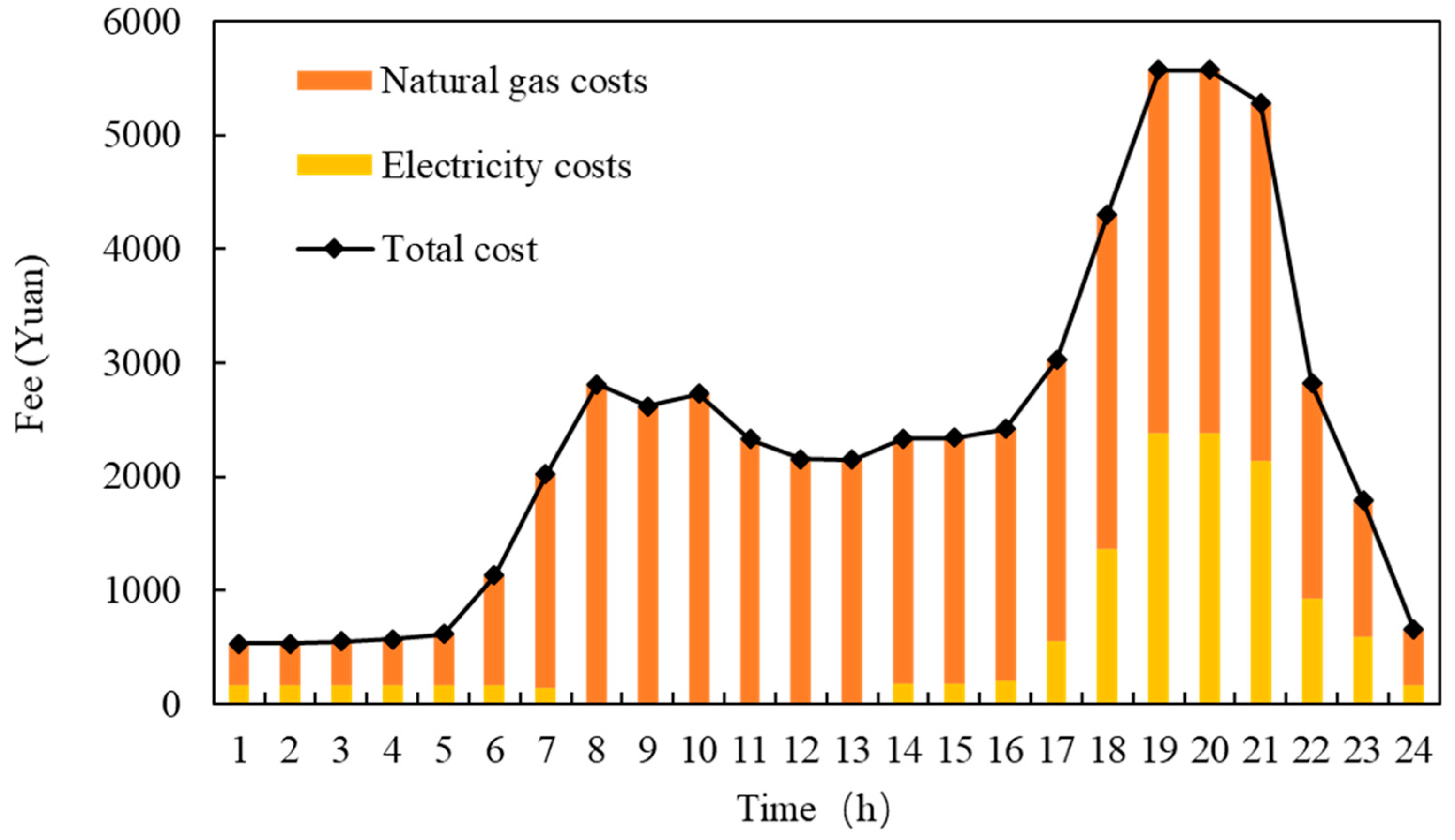
4.1. Operating Costs

Operational costs are the sum of energy procurement costs and equipment maintenance costs, and can be represented by the following equation:
F e c o = C o p + C e n
In this equation, F e c o represents operational costs, yuan, and C o p denotes equipment maintenance costs, yuan. Ideally, the maintenance costs of each device are directly proportional to its output power and operating time. C e n stands for energy procurement costs, yuan. Both can be expressed by the following formulas, respectively:
C o p = t = 1 T [ λ W T P W T t + λ P V P P V t + λ G T P G T t + λ G B P G B ( t ) + λ E C P E C ( t ) + λ R C P R C ( t ) + λ E S P E S ( t ) + λ T S P T S ( t ) ] Δ t
In this equation, P X ( t ) denotes the average output power of device X during the time interval Δ t from time t − 1 to t, kW, and λ X represents the operational and maintenance cost coefficient of device X. The subscripts of the variables have been explained previously in the text.
C e n = δ g a s t = 1 T [ F G T ( t ) + F G B ( t ) ] Δ t + δ e l t = 1 T P g r i d ( t ) Δ t
In this equation, δ g a s and δ e l respectively represent the prices of natural gas and electricity, yuan/kWh. FGT(t), FGB(t), and Pgrid(t) respectively denote the average combustion rates of natural gas in a micro gas turbine, the average combustion rate of natural gas in a gas boiler, and the average power supplied by the electrical grid during the Δ t time interval from time t – 1 to t, kW.

4.2. Carbon Emissions

Carbon emissions resulting from power plant electricity generation and those arising from natural gas combustion are directly proportional to the energy output of the power plant and the quantity of natural gas burned, respectively. The calculation formula is expressed as follows:
F c a r b o n = t = 1 T { λ g a s [ F G B ( t ) + F G T ( t ) ] + λ e l P g r i d ( t ) } Δ t
In this equation, F c a r b o n represents carbon emissions, t/CO2, while λ g a s and λ e l respectively denote the carbon emission coefficients associated with natural gas and electricity from the grid in the energy sector.

4.3. Energy Balance Constraints

Considering negligible losses on the energy bus, in accordance with the principle of energy conservation, the sum of power on both sides should be equal, as indicated by:
P g r i d + P W T + P P V + P E G T = P E + P E C + P E S C P E S D
P H G T + P G B = P H + P R C + P T S C P T S D
η E C P E C + η R C P R C = P C
In these equations, P g r i d represents the power supplied by the power plant to the grid, kW, while P E , P H , and P C respectively denote the electrical load, heating load, and cooling load of the users, kW.

4.4. Equipment Operational Constraints

In a low-carbon integrated energy system, the operational power of each device should fall within the range of the device’s maximum and minimum power levels to ensure the long-term safe operation of the equipment.
0 P G T P G T   m a x
0 P G B P G B   m a x
0 P C E C P C E C   m a x
0 P H R C P H R C   m a x
0 P g r i d P g r i d   m a x
0 F G B + F G T F m a x
In these equations, P G T   m a x , P G B   m a x ,  P C E C   m a x , and P H R C   m a x respectively represent the maximum output power of micro gas turbines, gas boilers, electric chillers, and absorption chillers, kW. P g r i d   m a x and F m a x denote the maximum electrical power supplied by the grid and the maximum natural gas flow rate from the natural gas pipeline, kW. Other variables have been defined in the preceding text and will not be reiterated.

4.5. Optimization Method
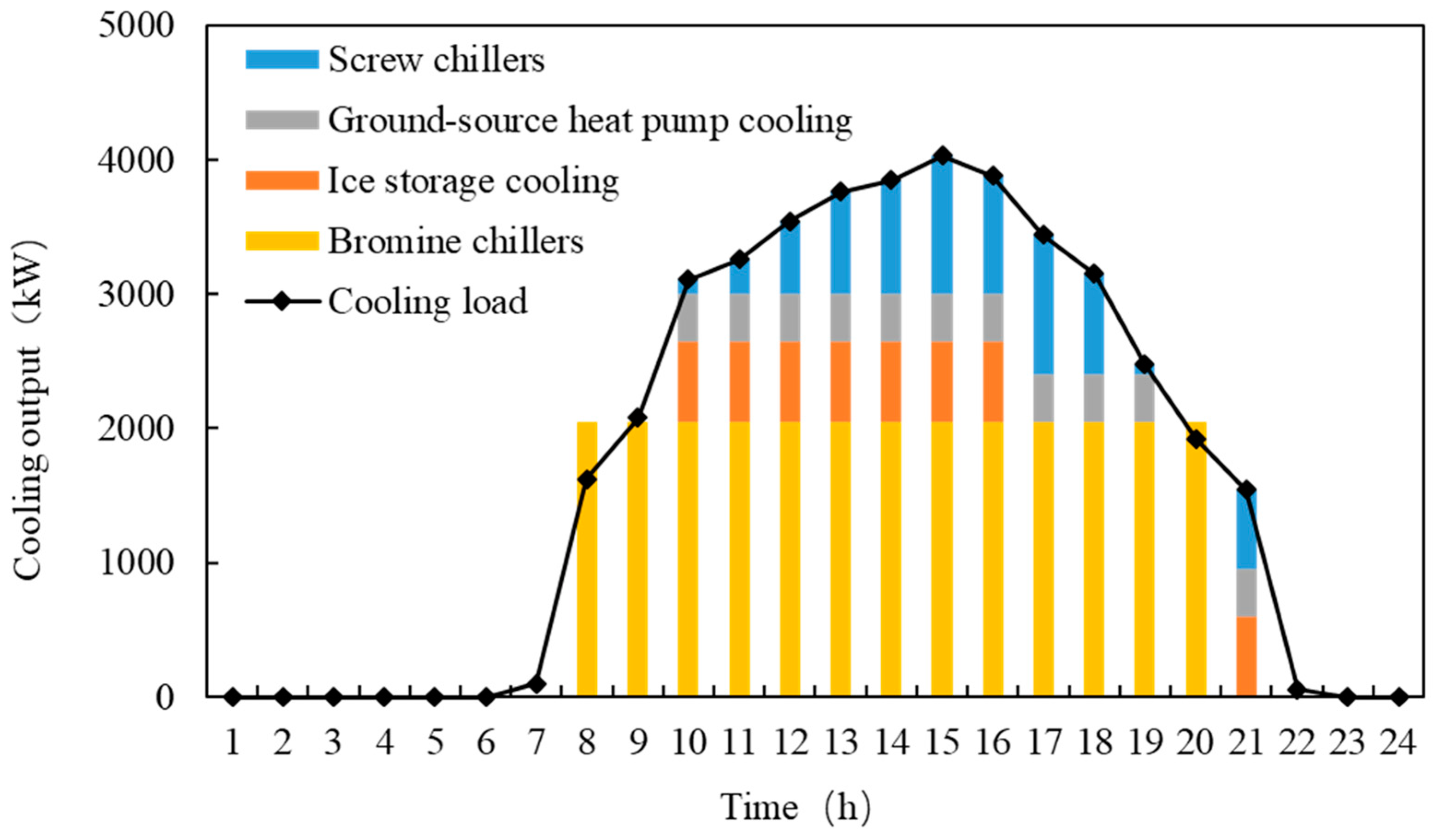
The firefly algorithm (FA) is a stochastic optimization algorithm based on swarm intelligence derived from the study of the mating behavior of fireflies in nature. In this algorithm, each individual is treated as a particle within the search space. Particle movement in the search space is guided by the emitted light intensity and light absorption coefficient of neighboring particles. The movement of a particle is directed towards positions with higher fluorescence values, where fluorescence corresponds to the fitness function value. Therefore, individuals navigate the dynamic decision space by seeking positions with the highest fluorescence values to determine the optimal value of the fitness function.
Evidently, the FA comprises two key elements: luminosity and attractiveness. Luminosity reflects the quality of the firefly’s current position and determines its movement direction, while attractiveness governs the distance the firefly will move. Through the continuous updating of luminosity and attractiveness, the algorithm achieves goal optimization. The relative brightness of a firefly is expressed as:
I = I 0 × e γ r i j
In this equation, I0 represents the maximum self-luminosity of fireflies at the center (r = 0), which is associated with the objective function value. The higher the objective function value, the greater the self-luminosity. Γ denotes the light intensity absorption coefficient and may be treated as a constant. Rij stands for the spatial distance between firefly I and j. When solving discrete problems, the distance can be defined based on the actual situation using the following expression:
β = β 0 × e γ r i j = x i x j = k = 1 d ( x i , k x j , k )
In this equation, d denotes the spatial dimension and xi,k represents the kth component of firefly I in a d-dimensional space.
Firefly attractiveness can be expressed by the following equation:
β = β 0 × e γ r i j 2
In this equation, β0 represents the maximum attractiveness, which is the attractiveness at the light source location (r = 0); due to the gradual attenuation of fluorescence with increasing distance and absorption by the propagation medium, an optical intensity absorption coefficient is introduced to capture this characteristic, and it can be set as a constant.
The position update of firefly I movement towards firefly j is calculated using the following formula:
x i = x i + β × ( x j x i ) + α × ( r a n d 1 / 2 )
In this equation, xi and xj represent the spatial positions of fireflies I and j, respectively. A denotes the step size factor, a constant within the range [0, 1]. Rand is a random factor uniformly distributed in the range [0, 1].
The light absorption coefficient γ has a significant impact on the attractiveness β, determining the individual firefly’s movement span, convergence speed, and other factors. When the distance between two fireflies is relatively small, the expansion of the attractiveness function is as follows:
β = β 0 × e γ r i j 2 = β 0 ( 1 γ r i j 2 + 0.5 γ 2 r i j 4 + )
If the light absorption coefficient approaches zero, the attractiveness tends towards β0. Thus, the position update formula is:
x i = x i + β 0 × ( x j x i ) + α × ( r a n d 1 / 2 )
If β0 is equal to 1, the position update formula is as follows:
x i = x j + α × ( r a n d 1 / 2 )
In this context, if the emitted light from fireflies undergoes no attenuation in space, each firefly can directly locate the optimal and brightest individual within its vicinity.
If the light intensity absorption coefficient γ is relatively large, then β also takes a larger value. The position update formula is as follows:
x i = x i + α × ( r a n d 1 / 2 )
The step size factor α can enhance the individual diversity, expand the algorithm’s search capability, and prevent premature convergence. Its value should be correlated with the range of the search space and the dimensionality.
The vector of the design variables that will be determined in the optimization process could be described as:
V e c t o r = Γ F e c o , F c a r b o n , P int , P W T ( t ) , P P V ( t ) , P G T T ( t ) , P G B ( t ) , P E C ( t ) , P R C ( t ) , P E S ( t ) , P T S ( t )
In this equation, F e c o , F c a r b o n , P int are the three objectives of objective optimization model. P W T ( t ) , P P V ( t ) , P G T T ( t ) , P G B ( t ) , P E C ( t ) , P R C ( t ) , P E S ( t ) , P T S ( t ) are the running state of each equipment time by time.

5. Case Study

Taking an industrial park as an example, the actual thermal load of the region is 4.8 MW and the actual cooling load is 4 MW. The power load is 4 MW, with a typical load curve shown in Figure 2. The weighting coefficients α, β, and γ in objective function are 0.3, 0.3, 0.4. The integrated energy system in the region operates in a grid-connected mode with self-consumption. The installed capacity of photovoltaics is 1.2 MW, and a ground-source heat pump system with a design cooling load of 350 kW is used. Moreover, the efficiency parameters of electrical efficiency, thermal efficiency, and the natural gas utilization efficiency are described in Table 1.
Figure 3 illustrates the cooling demand during the daytime and how it is satisfied by various equipment. During the night time, ice storager cooling generates more cooling for daytime. It can be observed that during the summer, the main cooling supply relies on the coupling of screw compressors and gas engine-driven bromine chillers. Ice storage tanks are used for overnight cooling storage, which significantly reduces the peak load of the screw chiller units.
Figure 4 illustrates the typical daily power output of different equipment during the summer, in which the equipment power consumption is negative. The main power consumption components of the multi-energy coupling system include nighttime cooling storage power consumption, screw chiller power consumption during the day, ground-source heat pump power consumption, and bromine chiller power consumption. The ice cooling storager generates more cooling for daytime during the night time. The power sources mainly consist of grid electricity, internal combustion engine generation, and photovoltaic (PV) generation, with a higher reliance on purchasing electricity from the grid.
Figure 5 shows the typical daily energy costs during the summer, with natural gas prices being relatively high during the project design phase. To balance the project’s goals of being both clean and economical, a smaller internal combustion engine with a capacity of only 1250 kW power output and 1350 kW heating output was chosen, along with 1200 kW of photovoltaic power. According to the output of Figure 4, the hourly energy cost is calculated. It can be seen that the highest hourly cost in summer occurs from 19:00 to 20:00, mainly due to the large demand for cooling load and electrical load at this time, and this period is also the peak electricity price.
Figure 6 displays the typical daily heating output of different equipment during the winter. The ground-source heat pump operates 24 h a day as a renewable energy supply. Due to the small capacity design of internal combustion engines, the heating output of waste heat boilers coupled with internal combustion engines is not high, and the main heat load is provided by gas boilers.
Figure 7 illustrates the typical daily power output of different equipment during the winter. The power consumption of the equipment is negative, and the ground-source heat pump consumes electrical energy 24 h a day. The power source mainly comes from the municipal grid power, internal combustion engine power generation, and photovoltaic power generation.
The typical daily energy cost in winter is shown in Figure 8. Due to the high gas consumption of gas-fired boilers for heating in winter, the gas cost is high. When there is a feed-in tariff, the amount of electricity purchased from the municipal grid decreases significantly, while the gas consumption cost increases significantly, with some online revenue. The feed-in tariff can further reduce the energy consumption cost of system operation and improve the economy of multi-energy coupling systems.
The integrated optimization model uses a normalized linear weighted method to optimize the objective and obtain the optimal weight ratio. The integrated energy system reduces the user’s electricity cost by 3.4 cents/kW·h compared to the grid, reflecting the project’s economic efficiency. It saves 2564 tons of standard coal per year, reduces CO2 emissions by 7512 tons, and reduces NOx emissions by 17.2 tons compared with a traditional coal-fired energy system. The electricity supply from the grid is reduced by 6.5%. It is beneficial to energy conservation, emission reduction, and green development in the park.

6. Conclusions

Research into optimizing operational control strategies for comprehensive energy systems at the park level involves establishing optimization models for diverse system components. An intelligent algorithm-based operational optimization model for multi-energy coupled systems was constructed using the firefly optimization algorithm. Delving deeper into the operational characteristics of this multi-energy coupled system, the following specific conclusions are drawn:
(1)
To cater to the diverse energy demands of the park, including cold, heat, electricity, and gas, a multi-energy complementary system is formulated, incorporating distributed clean energy and energy storage. This system is designed based on the principle of energy–economy–environment integration, and its unique features are thoroughly analyzed.
(2)
Leveraging the firefly optimization algorithm, an operational optimization model is formulated for multi-energy coupling systems. This approach offers precision in determining the operational state parameters of these systems.
(3)
An autonomous, economical, energy-efficient, low-carbon, and optimized operational mode has been successfully established.

Author Contributions

H.C. and S.W. contributed on the conception and design of the study. Y.G. and Y.Y. wrote the draft of this manuscript. X.J., L.J., K.L. and X.Z. analyzed the computing results. Moreover, all authors contributed to the revision of the manuscript. All authors have read and agreed to the published version of the manuscript.

Funding

This work was supported by State Grid Corporation of China Headquarters Science and Technology Project—Research and Application of Carbon Emission Reduction Methodology and Value-Added Service Technology in the Demand Side Supporting ‘Power+Energy Efficiency Service’ (Project Number: 5400-202140500A-0-5-ZN).

Institutional Review Board Statement

Not applicable.

Informed Consent Statement

Not applicable.

Data Availability Statement

The data presented in this study are available in the article.

Conflicts of Interest

The authors declare that this study received funding from State Grid Corporation of China. The funder was not involved in the study design, collection, analysis, interpretation of data, the writing of this article or the decision to submit it for publication.

References

  1. Yan, J.Y.; Yang, Y.; Campana, P.E.; He, J.J. City-level analysis of subsidy-free solar photovoltaic electricity price, profits and grid parity in China. Nat. Energy 2019, 4, 709–717. [Google Scholar] [CrossRef]
  2. Wen, Q.; Hong, J.K.; Liu, G.W.; Xu, P.P.; Tang, M.H.; Li, Z.F. Regional efficiency disparities in China’s construction sector: A combination of multiregional input-output and data envelopment analyses. Appl. Energy 2020, 257, 113964. [Google Scholar] [CrossRef]
  3. Zhang, T.; Yan, X.; Zhang, R.; Ye, Q.; Ma, J. Optimized Dispatching for Integrated Energy System With Wind Power. Front. Energy Res. 2022, 10, 917805. [Google Scholar] [CrossRef]
  4. Ma, C.J.; Menke, J.H.; Dasenbrock, J.; Braun, M.; Haslbeck, M.; Schmid, K.H. Evaluation of energy losses in low voltage distribution grids with high penetration of distributed generation. Appl. Energy 2019, 256, 113907. [Google Scholar] [CrossRef]
  5. Zhang, T.; Hu, Z. Optimal Scheduling Strategy of Virtual Power Plant With Power-to-Gas in Dual Energy Markets. IEEE Trans. Ind. Appl. 2022, 58, 2921–2929. [Google Scholar] [CrossRef]
  6. Ghasemi, H.; Aghaei, J.; Gharehpetian, G.B.; Safdarian, A. MILP model for integrated expansion planning of multi-carrier active energy systems. IET Gener. Transm. Distrib. 2019, 13, 1177–1189. [Google Scholar] [CrossRef]
  7. de la Nieta, A.A.S.; Paterakis, N.G.; Gibescu, M. Participation of photovoltaic power producers in short-term electricity markets based on rescheduling and risk-hedging mapping. Appl. Energy 2020, 266, 114741. [Google Scholar] [CrossRef]
  8. Bloess, A. Modeling of combined heat and power generation in the context of increasing renewable energy penetration. Appl. Energy 2020, 267, 114727. [Google Scholar] [CrossRef]
  9. Amuzu-Sefordzi, B.; Martinus, K.; Tschakert, P.; Wills, R. Disruptive innovations and decentralized renewable energy systems in Africa: A socio-technical review. Energy Res. Soc. Sci. 2018, 46, 140–154. [Google Scholar] [CrossRef]
  10. Mancarella, P. MES (multi-energy systems): An overview of concepts and evaluation models. Energy 2014, 65, 1–17. [Google Scholar] [CrossRef]
  11. Wang, R. Multi-objective configuration optimization method for a diesel-based hybrid energy system. Energy Rep. 2020, 6, 2146–2152. [Google Scholar] [CrossRef]
  12. Wang, Y.L.; Wang, Y.D.; Huang, Y.J.; Yang, J.L.; Ma, Y.Z.; Yu, H.Y.; Zeng, M.; Zhang, F.; Zhang, Y. Operation optimization of regional integrated energy system based on the modeling of electricity-thermal-natural gas network. Appl. Energy 2019, 251, 113410. [Google Scholar] [CrossRef]
  13. Ju, L.W.; Li, H.H.; Zhao, J.W.; Chen, K.T.; Tan, Q.K.; Tan, Z.F. Multi-objective stochastic scheduling optimization model for connecting a virtual power plant to wind-photovoltaic-electric vehicles considering uncertainties and demand response. Energy Convers. Manag. 2016, 128, 160–177. [Google Scholar] [CrossRef]
  14. Tan, J.; Wu, Q.W.; Hu, Q.R.; Wei, W.; Liu, F. Adaptive robust energy and reserve co-optimization of integrated electricity and heating system considering wind uncertainty. Appl. Energy 2020, 260, 114230. [Google Scholar] [CrossRef]
  15. Lyu, J.; Zhang, S.; Cheng, H.; Yuan, K.; Song, Y.; Fang, S. Optimal Sizing of Energy Station in the Multi-energy System Integrated with Data Center. IEEE Trans. Ind. Appl. 2021, 57, 1222–1234. [Google Scholar] [CrossRef]
Figure 1. Low-carbon integrated energy system framework.
Applsci 14 05433 g001
Figure 2. Load demands.
Applsci 14 05433 g002
Figure 3. Cooling output of different equipment.
Applsci 14 05433 g003
Figure 4. Power output of different equipment.
Applsci 14 05433 g004
Figure 5. Cost of the integrated energy system.
Applsci 14 05433 g005
Figure 6. Heating output of typical daily equipment in winter.
Applsci 14 05433 g006
Figure 7. Power supply of typical daily equipment in winter.
Applsci 14 05433 g007
Figure 8. Typical daily energy costs in winter.
Applsci 14 05433 g008
Table 1. Efficiency parameters.
ParametersηEηHηGB
Value40%90%98%
Disclaimer/Publisher’s Note: The statements, opinions and data contained in all publications are solely those of the individual author(s) and contributor(s) and not of MDPI and/or the editor(s). MDPI and/or the editor(s) disclaim responsibility for any injury to people or property resulting from any ideas, methods, instructions or products referred to in the content.

