
Response and Fracture of EMT Carbon Steel Round-Hole Tubes with Different Hole Orientations and Different Hole Diameters under Cyclic Bending


Abstract
:1. Introduction
2. Experiments
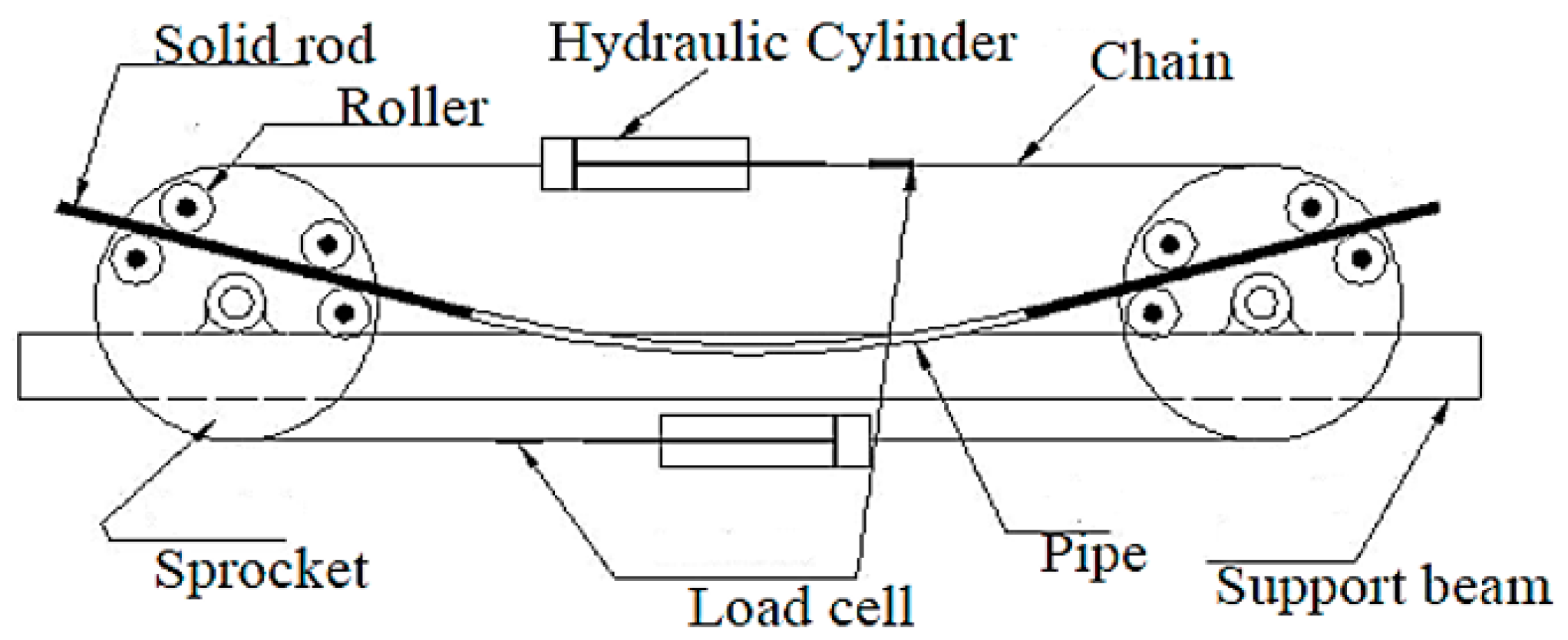
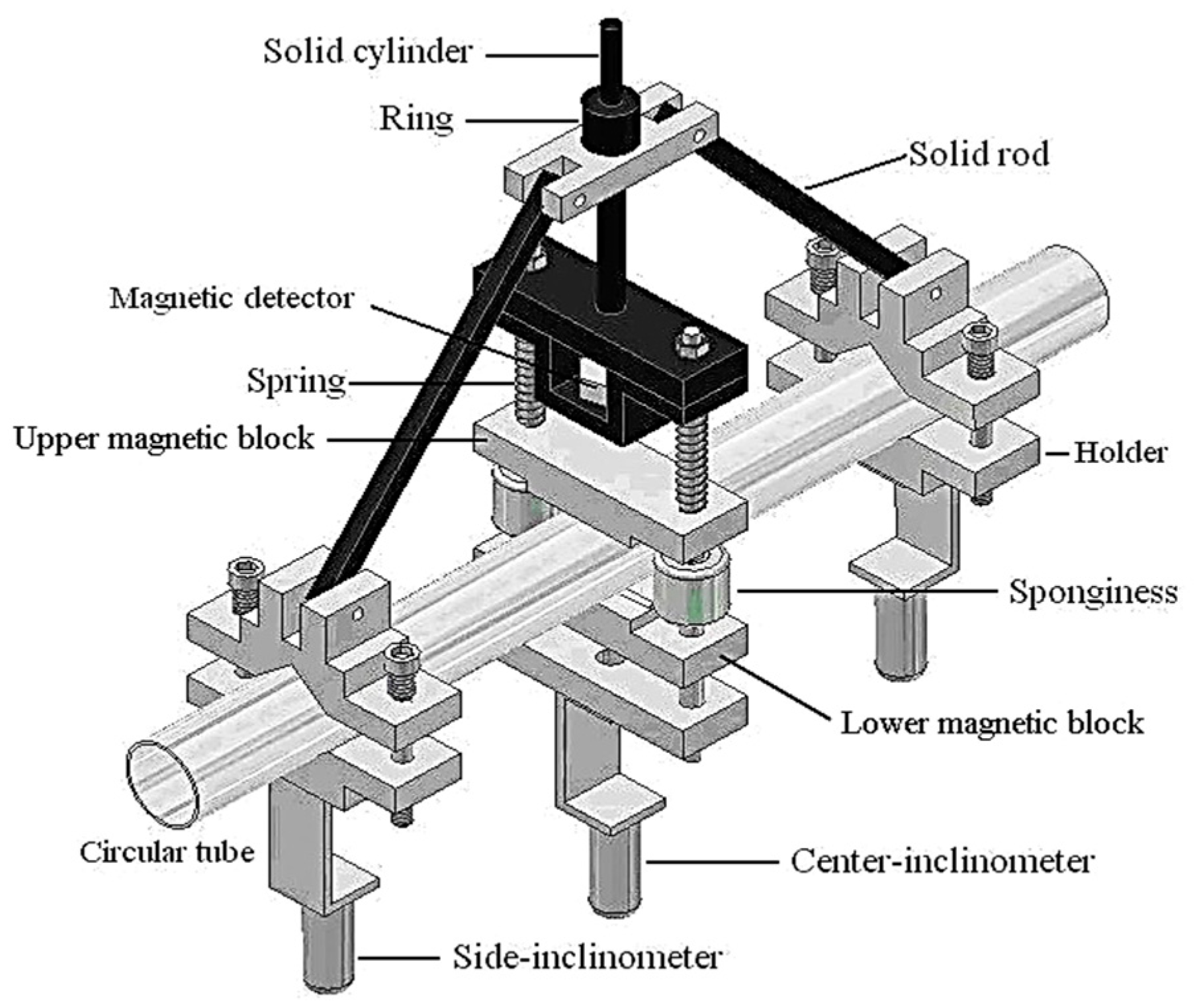
2.1. Experimental Devices
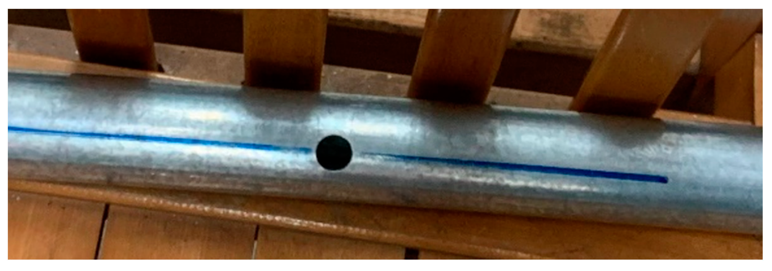
2.2. Material and Specimens
2.3. Test Procedures
3. Experimental Results and Discussion
3.1. M–κ Relationships
3.2. ∆D/Do–κ Relationships
3.3. Controlled Curvature (κc/κo)–Nf Relationships
4. Conclusions
- (1)
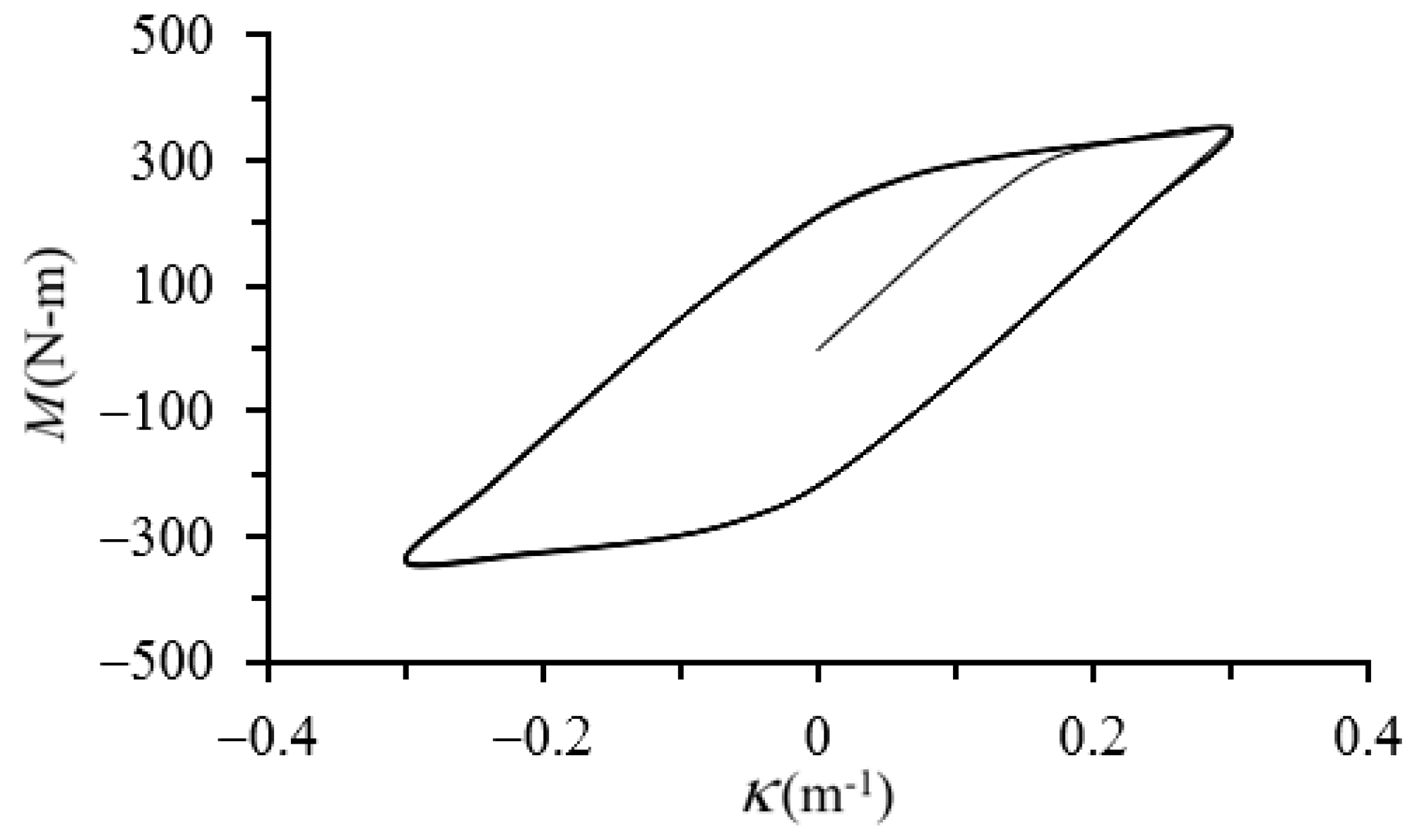
- From the experimental M–κ relationships, it is observed that as the κ increases, the M also increases. Under cyclic bending loads, the M–κ relationship exhibits a stable loop until eventual buckling failure. Results also indicate that for different ϕ and d, the M–κ relationships show similar loops. This phenomenon is consistent with the experimental results of Lee et al. [27].
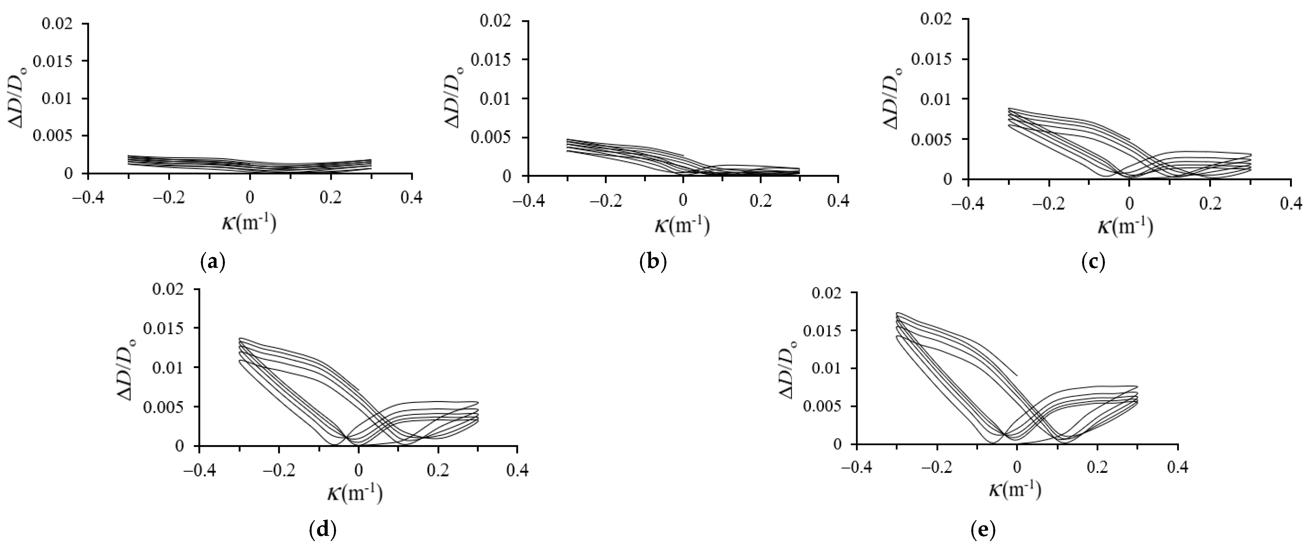
- (2)
- In the experimental ΔD/Do–κ relationships, higher κ leads to increased ΔD/Do. Larger d or smaller ϕ values correspond to increased ΔD/Do. This phenomenon is consistent with the experimental results of Lee et al. [27]. Additionally, under cyclic bending loads, the ΔD/Do–κ relationships exhibit a ratcheting, unsymmetrical, bowtie, and growing trend. The larger d or smaller ϕ is, the more serious the asymmetry is. This phenomenon is consistent with the experimental results of Lee et al. [27].
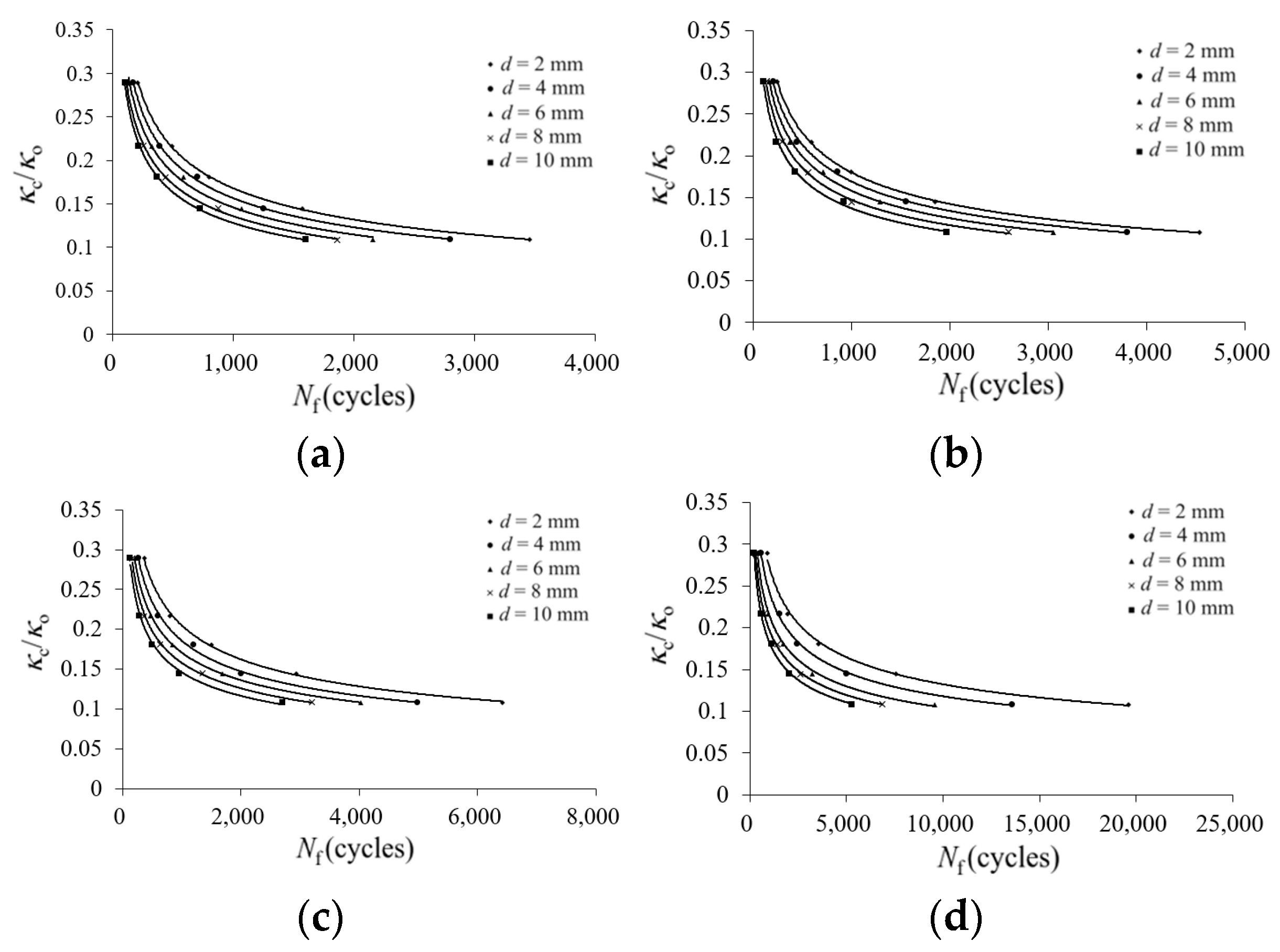
- (3)
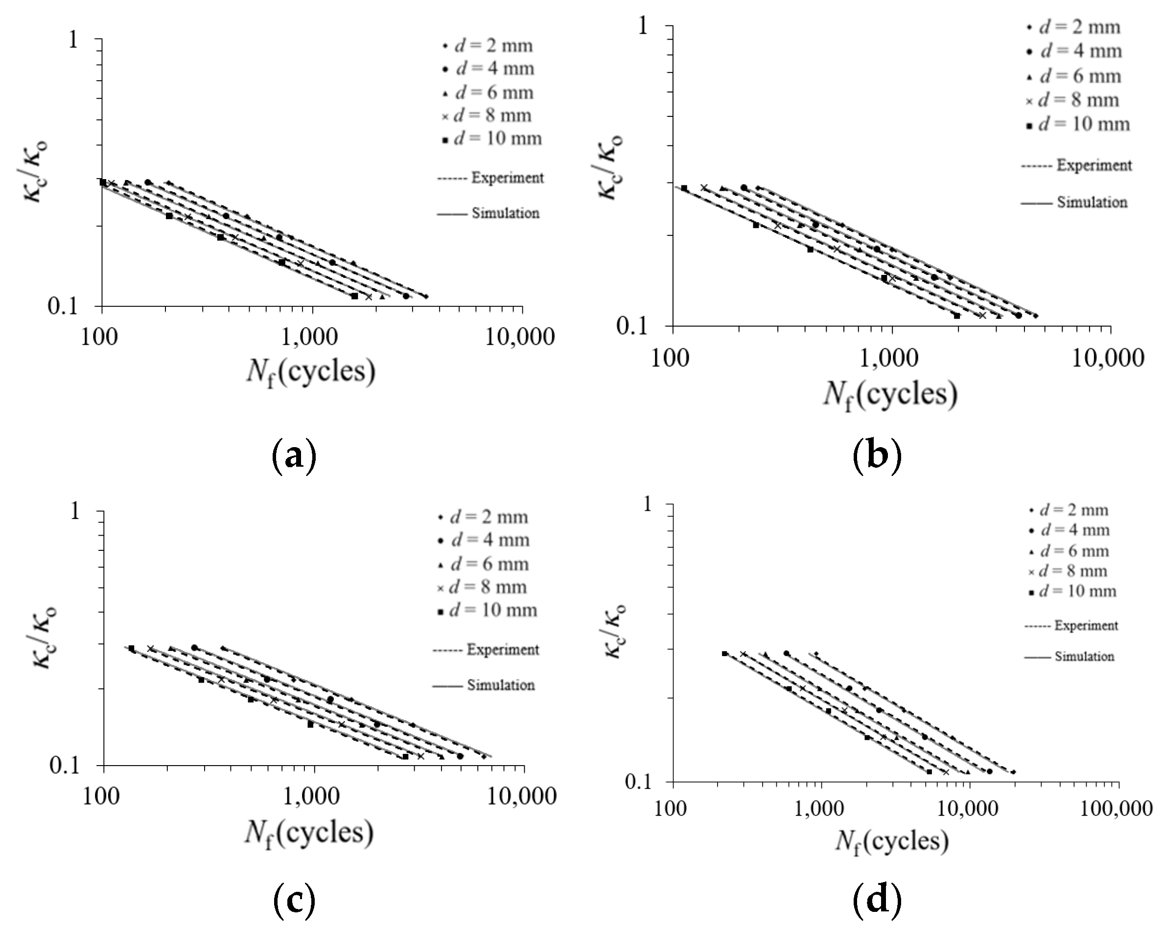
- The experimental κc/κo–Nf relationships reveal that, when ϕ and d are fixed, larger κc/κo leads to fewer Nf. Fixing ϕ and κc/κo, larger d results in fewer Nf. Conversely, when fixing d and κc/κo, larger ϕ leads to more Nf. When ϕ is fixed, the relationships of κc/κo–Nf for five different d on double logarithmic coordinates exhibit five straight lines. This phenomenon is consistent with the experimental results of Lee et al. [27]. However, for a certain ϕ, they show almost-parallel lines, while we found non-parallel lines.
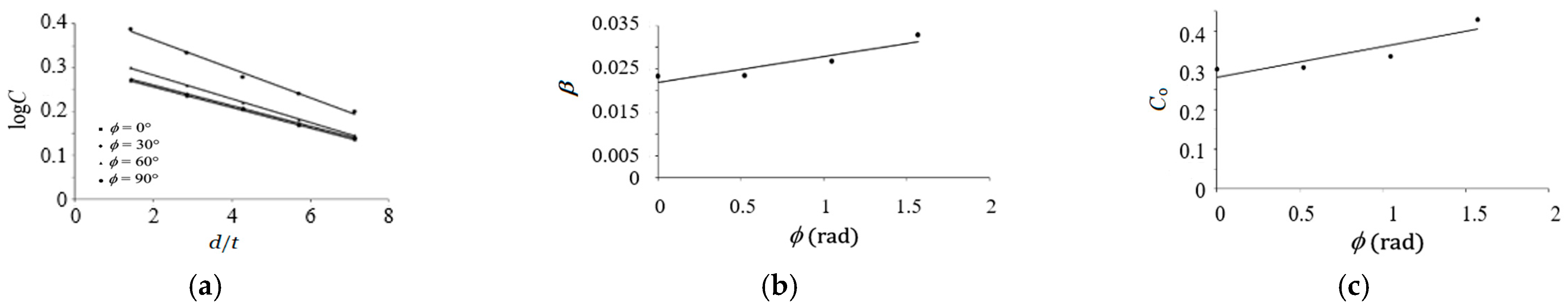
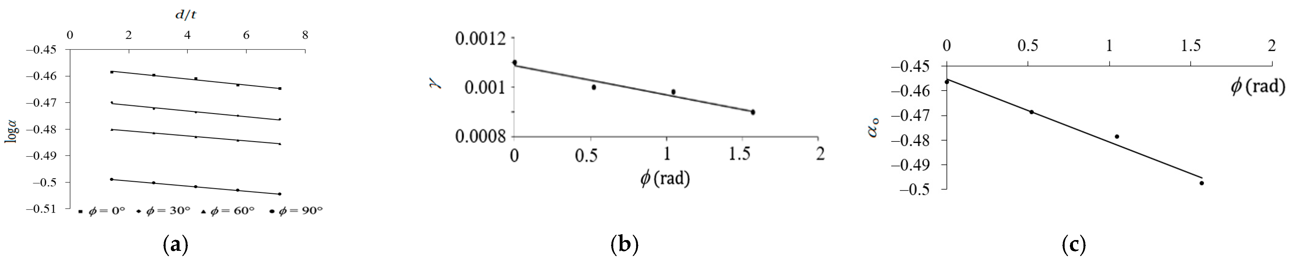
- (4)
- This study adopts the formula (Equation (1)) proposed by Kyriakides and Shaw [1] to describe the κc/κo–Nf relationships. The formulation of the material parameter C in Equation (2), proposed by Lee et al. [27], was used in this study. The material parameters β and Co were derived from Equations (3) and (4), respectively. Additionally, the material parameter α (Equation (5)) was newly proposed based on the experimental data. The material parameters γ and αo were derived from Equations (6) and (7), respectively. The theoretical equations (Equations (1)–(4) and (5)–(7)) were employed to describe the κc/κo–Nf relationships for EMT carbon steel RHTs under cyclic bending with ϕ = 0°, 30°, 60°, and 90° and various d (dashed lines in Figure 13a–d), and the results of experimental and theoretical analyses are reasonably consistent.
Author Contributions
Funding
Data Availability Statement
Acknowledgments
Conflicts of Interest
References
- Kyriakides, S.; Shaw, P.K. Inelastic buckling of tubes under cyclic bending. J. Pres. Ves. Tech. 1987, 109, 169–178. [Google Scholar] [CrossRef]
- Corona, E.; Kyriakides, S. An experimental investigation of the degradation and buckling of circular tubes under cyclic bending and external pressure. Thin-Walled Struct. 1991, 12, 229–263. [Google Scholar] [CrossRef]
- Corona, E.; Kyriakides, S. Asymmetric collapse modes of pipes under combined bending and pressure. Int. J. Solids Struct. 2000, 24, 505–535. [Google Scholar] [CrossRef]
- Corona, E.; Lee, L.H.; Kyriakides, S. Yield anisotropic effects on buckling of circular tubes under bending. Int. J. Solids Struct. 2006, 43, 7099–7118. [Google Scholar] [CrossRef]
- Limam, A.; Lee, L.H.; Corana, E. Inelastic wrinkling and collapse of tubes under combined bending and internal pressure. Int. J. Mech. Sci. 2010, 52, 37–47. [Google Scholar] [CrossRef]
- Limam, A.; Lee, L.H.; Corona, E.; Kyriakides, S. On the collapse of dented tubes under combined bending and internal pressure. Int. J. Solids Struct. 2012, 55, 1–12. [Google Scholar] [CrossRef]
- Bechle, N.J.; Kyriakides, S. Localization of NiTi tubes under bending. Int. J. Solids Struct. 2014, 51, 967–980. [Google Scholar] [CrossRef]
- Jiang, D.; Kyriakides, S.; Bechle, N.J.; Landis, C.M. Bending of pseudoelastic NiTi tubes. Int. J. Solids Struct. 2017, 124, 192–214. [Google Scholar] [CrossRef]
- Kazinakis, K.; Kyriakides, S.; Jiang, D.; Bechle, N.J.; Landis, C.M. Buckling and collapse of pseudoelastic NiTi tubes under bending. Int. J. Solids Struct. 2021, 221, 2–17. [Google Scholar] [CrossRef]
- Yuan, W.; Mirmiran, A. Buckling analysis of concrete-filled FRP tubes. Int. J. Struct. Stab. Dyn. 2001, 1, 367–383. [Google Scholar] [CrossRef]
- Elchalakani, M.; Zhao, X.L.; Grzebieta, R.H. Plastic mechanism analysis of circular tubes under pure bending. Int. J. Mech. Sci. 2002, 44, 1117–1143. [Google Scholar] [CrossRef]
- Elchalakani, M.; Zhao, X.L.; Grzebieta, R.H. Variable amplitude cyclic pure bending tests to determine fully ductile section slenderness limits for cold-formed CHS. Eng. Struct. 2006, 28, 1223–1235. [Google Scholar] [CrossRef]
- Zhi, X.D.; Fan, F.; Shen, S.Z. Failure mechanism of single-layer cylindrical reticulated shells under earthquake motion. Int. J. Struct. Stab. Dyn. 2012, 12, 233–249. [Google Scholar] [CrossRef]
- Yazdani, H.; Nayebi, A. Continuum damage mechanics analysis of thin-walled tube under cyclic bending and internal constant pressure. Int. J. Appl. Mech. 2013, 5, 1350038. [Google Scholar] [CrossRef]
- Guo, L.; Yang, S.; Jiao, H. Behavior of thin-walled circular hollow section tubes subjected to bending. Thin-Walled Struct. 2013, 73, 281–289. [Google Scholar] [CrossRef]
- Elchalakani, M.; Karrech, A.; Hassanein, M.F.; Yang, B. Plastic and yield slenderness limits for circular concrete filled tubes subjected to static pure bending. Thin-Walled Struct. 2016, 109, 50–64. [Google Scholar] [CrossRef]
- Shamass, R.; Alfano, G.; Guarracino, F. On elastoplastic buckling analysis of cylinders under nonproportional loading by differential quadrature method. Int. J. Struct. Stab. Dyn. 2017, 17, 1750072. [Google Scholar] [CrossRef]
- Chegeni, B.; Jayasuriya, S.; Das, S. Effect of corrosion on thin-walled pipes under combined internal pressure and bending. Thin-Walled Struct. 2019, 143, 106218. [Google Scholar] [CrossRef]
- Jin, S.; Cheng, P.; Saneian, M.; Yong, B. Mechanical behavior of thin tubes under combined axial compression and bending. Thin-Walled Struct. 2021, 159, 107255. [Google Scholar] [CrossRef]
- Silveira1, T.; Pinto, V.T.; Neufeld, J.P.S.; Pavlovic, A.; Rocha, L.A.O.; Santos, E.D.; Isoldi, L.A. Applicability evidence of constructal design in structural engineering: Case study of biaxial elasto-plastic buckling of square steel plates with elliptical cutout. J. Appl. Comp. Mech. 2021, 7, 922–934. [Google Scholar]
- He, Z.R.; Li, G.J.; Yang, J.C.; Guo, X.Z.; Duan, X.Y.; Guo, W.; Liu, X.; Deng, Y.Y.; Cheng, C. Insight into the deformation transition effect in free bending of tubes. Mat. Lett. 2023, 348, 134673. [Google Scholar] [CrossRef]
- Wang, J.; Li, J.R.; Li, H.; Lv, L.Y. Behaviour of square concrete-filled steel tubes reinforced with internal latticed steel angles under bending. Structures 2023, 48, 1436–1454. [Google Scholar] [CrossRef]
- Wu, Z.; Li, J.; Shi, L.; Chen, X. Effect of stacking configuration on the mechanical property and damage behavior of braided composite tube under three-point bending. Thin-Walled Struct. 2023, 187, 110762. [Google Scholar] [CrossRef]
- Pan, W.F.; Wang, T.R.; Hsu, C.M. A curvature-ovalization measurement apparatus for circular tubes under cyclic bending. Exp. Mech. 1998, 38, 99–102. [Google Scholar] [CrossRef]
- Lee, K.L.; Hsu, C.M.; Pan, W.F. Viscoplastic collapse of sharp-notched circular tubes under cyclic bending. Acta Mech. Solida Sin. 2013, 26, 629–641. [Google Scholar] [CrossRef]
- Lee, K.L.; Chang, K.H.; Pan, W.F. Failure life estimation of sharp-notched circular tubes with different notch depths under cyclic bending. Struct. Eng. Mech. 2016, 60, 387–404. [Google Scholar] [CrossRef]
- Lee, K.L.; Weng, M.L.; Pan, W.F. On the failure of round-hole tubes under cyclic bending. J. Chi. Soc. Mech. Eng. 2019, 40, 663–673. [Google Scholar]


Disclaimer/Publisher’s Note: The statements, opinions and data contained in all publications are solely those of the individual author(s) and contributor(s) and not of MDPI and/or the editor(s). MDPI and/or the editor(s) disclaim responsibility for any injury to people or property resulting from any ideas, methods, instructions or products referred to in the content. |
© 2024 by the authors. Licensee MDPI, Basel, Switzerland. This article is an open access article distributed under the terms and conditions of the Creative Commons Attribution (CC BY) license (https://creativecommons.org/licenses/by/4.0/).
Share and Cite
Pan, W.-F.; Chen, Y.-A. Response and Fracture of EMT Carbon Steel Round-Hole Tubes with Different Hole Orientations and Different Hole Diameters under Cyclic Bending. Appl. Sci. 2024, 14, 5475. https://doi.org/10.3390/app14135475
Pan W-F, Chen Y-A. Response and Fracture of EMT Carbon Steel Round-Hole Tubes with Different Hole Orientations and Different Hole Diameters under Cyclic Bending. Applied Sciences. 2024; 14(13):5475. https://doi.org/10.3390/app14135475
Chicago/Turabian StylePan, Wen-Fung, and Yu-An Chen. 2024. "Response and Fracture of EMT Carbon Steel Round-Hole Tubes with Different Hole Orientations and Different Hole Diameters under Cyclic Bending" Applied Sciences 14, no. 13: 5475. https://doi.org/10.3390/app14135475