Article

The Two-Parameter Bifurcation and Evolution of Hunting Motion for a Bogie System

by
Shijun Wang
1,2,*,
Lin Ma
1 and
Lingyun Zhang
3
1
School of Mechatronic Engineering, Lanzhou Jiaotong University, Lanzhou 730070, China
2
Key Laboratory of System Dynamics and Reliability of Rail Transport Equipment of Gansu Province, Lanzhou 730070, China
3
School of Mechanical Engineering, Guilin University of Aerospace Technology, Guilin 541004, China
*
Author to whom correspondence should be addressed.
Appl. Sci. 2024, 14(13), 5492; https://doi.org/10.3390/app14135492
Submission received: 9 May 2024 / Revised: 18 June 2024 / Accepted: 22 June 2024 / Published: 25 June 2024
(This article belongs to the Section Mechanical Engineering)

Abstract

:
The complex service environment of railway vehicles leads to changes in the wheel–rail adhesion coefficient, and the decrease in critical speed may lead to hunting instability. This paper aims to reveal the diversity of periodic hunting motion patterns and the internal correlation relationship with wheel–rail impact velocities after the hunting instability of a bogie system. A nonlinear, non-smooth lateral dynamic model of a bogie system with 7 degrees of freedom is constructed. The wheel–rail contact relations and the piecewise smooth flange forces are the main nonlinear, non-smooth factors in the system. Based on Poincaré mapping and the two-parameter co-simulation theory, hunting motion modes and existence regions are obtained in the parameter plane consisting of running speed v and the wheel–rail adhesion coefficient μ. Three-dimensional cloud maps of the maximum lateral wheel–rail impact velocity are obtained, and the correlation with the hunting motion pattern is analyzed. The coexistence of periodic hunting motions is further revealed based on combined bifurcation diagrams and multi-initial value phase diagrams. The results show that grazing bifurcation causes the number of wheel–rail impacts to increase at a low-speed range. Periodic hunting motion with period number n = 1 has smaller lateral wheel–rail impact velocities, whereas chaotic motion induces more severe wheel–rail impacts. Subharmonic periodic hunting motion windows within the speed range of chaotic motion, pitchfork bifurcation, and jump bifurcation are the primary forms that induce the coexistence of periodic motion.

1. Introduction

The railway vehicle system operates in diverse geographical and climatic environments, encompassing plains, hills, mountainous areas, and plateaus. There are notable variations in temperature, humidity, altitude, sandstorms, rain, and snow along the line, which makes the operation conditions of the railway vehicle system complex [1]. The complex operating conditions may reduce the critical speed below the operational speed, resulting in hunting instability. Consequently, it is imperative to investigate further the potential consequences of railway vehicles operating at speeds exceeding the critical speed.
Early studies on hunting stability were primarily conducted using linear models and subjected to a linear stability analysis [2,3,4,5,6]. The presence of nonlinear factors, such as wheel–rail contact relations, dry friction, flange forces, etc., makes the railway vehicle system a typical nonlinear and non-smooth system [7]. Based on the bifurcation theory, scholars have extensively focused on investigating the critical speed of railway vehicle systems. Huilgol [8] investigated the condition that the equilibrium position converted to a periodic solution and analyzed the stability of the periodic solution based on the Hopf–Friedrichs bifurcation theory. Xu et al. [9] conducted a comparison between the nonlinear and the linear critical speed. They emphasized the higher practical significance of the nonlinear critical velocity and analyzed the effect of suspended dampers on it. Ahmadian and Yang [10] considered creep force and the flange contact nonlinearities in a single wheelset system and found that the nonlinearities of suspensions significantly affect the hunting motion and nonlinear critical velocity. Zeng et al. [11,12] calculated the speed at which Hopf bifurcation occurs in the whole vehicle system based on a numerical simulation and verified it in a rolling test bed. Wagner [13] found that stable equilibrium points and periodic solutions coexist within a specific velocity interval when a wheelset system undergoes hunting instability via a subcritical Hopf bifurcation. Dong and Zhao [14] found that the form of bifurcation that initiates hunting instability may be the supercritical or subcritical Hopf bifurcations due to differences in vehicle system parameters. Yan and Zeng [15] investigated the influence of various wheel shapes on the type of Hopf bifurcation based on the enter manifold theorem. Guo et al. [16] analyzed the Hopf bifurcation behavior for a single wheelset system for resonant and non-resonant conditions. They found that increasing the longitudinal suspension stiffness increases the vehicle system stability. Thus, it can be seen that based on the bifurcation theory, the mechanism of hunting instability and the associated bifurcation types could be effectively analyzed to identify the critical speed of the system. At the same time, the effects of parameter changes on the critical speed and bifurcation types could be analyzed.
Exploring bifurcations, the evolution of periodic hunting motions at higher speed ranges and the analysis of wheel–rail impact characteristics have attracted the attention of many scholars. Petersen and True [17] found stationary, periodic, and chaotic motions with a numerical simulation in lateral dynamic models of a single wheelset and bogie system, respectively. Subsequently, True and co-workers performed a series of important works based on Cooperrider’s complex bogie and discovered its extremely diverse dynamic behavior, including multiple bifurcations and attractors [18,19,20,21]. Bifurcation-induced asymmetric branching was found as well as the coexistence of periodic and chaotic motion behavior [18,19]. Isaksen and True [20] analyzed the transit of hunting motion from equilibrium to chaotic motion in detail. They found high-order subharmonics in a very narrow parameter range, whereas the transit of periodic motion to chaotic motion initiated with Neimark–Sacker bifurcation. True [21] emphasized the dependence of critical velocity on the initial state and analyzed the influence of parameter changes. Gao [22,23,24,25] used consequence bifurcation diagrams to investigate asymmetric behavior in symmetric railway systems. Bustos [26] studied stable and unstable solutions near the critical velocity and analyzed the parameter sensitivity. Zboinski and Dusza [27,28] extended the bifurcation theory of railway vehicle systems in straight rails to research curved tracks. It was found that there are similar mechanisms of hunting instability and complex types of hunting motion and bifurcation forms in curved tracks. In addition, some studies have found that the primary hunting motion of vehicle systems at low speeds occurs during the speed-up of the vehicle system, which seriously affects passenger comfort [29,30,31]. Based on the above analysis, there are complex periodic motion patterns as well as bifurcation types in the speed range above the critical speed.
The nonlinear factors in the hunting motion mainly arise from the wheel–rail creep-slip forces and the wheel–rail impacts. In studying the cone-tread wheel and small-amplitude hunting instability, wheel–rail contact geometry relationships based on equivalent conicity linearization are widely used [32,33,34,35,36]. In studies using worn-type wheels, scholars have used polynomial fitting [37,38], least-squares fitting [39], measured data [12], and software simulations [40,41,42] to obtain nonlinear wheel–rail contact geometry relationships. In severe hunting instability, when the wheelset lateral displacement exceeds the wheel–rail clearance, it will be subjected to flange forces. A description of the flange force as a piecewise linear spring force is widely used [21,43,44], which makes the vector field of flange forces not differentiable at the inflection point and makes the system a typical non-smooth system. Polynomial fitting is often used to avoid non-smooth properties, which enables the utilization of various theories and methods suitable for smooth nonlinear systems [38,45]. However, it also has disadvantages, such as the widely used Wagner’s function is a five-order polynomial fitting [13]. Still, the direction of flange force at small displacement is opposite to the actual direction. Therefore, in the study of hunting motion with larger lateral displacements, it is crucial to fully consider the non-smooth and nonlinear characteristics of wheel–rail contact relations and wheel–rail impacts.
So far, the study of the hunting motion of railway vehicle systems based on the bifurcation theory mainly adopts single-parameter bifurcation, and a few two-parameter analyses have only obtained Hopf bifurcation lines in the parameter plane [46,47], which fails to effectively identify the mode types of periodic hunting motion. In this paper, the nonlinear, non-smooth wheel–rail contact relation and the effect of flange force are fully considered. The pattern types of periodic hunting motion are effectively identified in the two-parameter plane, their diversity and bifurcation characteristics are analyzed, and their wheel–rail impact characteristics are investigated. The paper is organized as follows. The lateral dynamic mode of a railway bogie system is presented in Section 2. In Section 3, the Poincaré sections are constructed, and the two-parameter co-simulation theory is briefly introduced. In Section 4, lateral dynamic characteristics of the bogie system are numerically analyzed. Based on the two-parameter co-simulation, the mode types and distribution laws of the periodic hunting motion in the (v, μ)-plane and the wheel–rail impact characteristics are studied in Section 4.1. Mechanisms of hunting instability, bifurcation, and transition laws of periodic hunting motion are studied in Section 4.2. Conclusions are drawn in Section 5.

2. Dynamic Model

A schematic diagram of a railway bogie lateral dynamic model is shown in Figure 1. The bogie system consists of one frame and two wheelsets, which are assumed to be rigid bodies. The primary suspension connects the wheelsets and frame, and the secondary suspension connects the frame and car body. The suspension system is simplified to linear springs and dampers, where the primary suspensions are K1x, K1y, K1z, C1x, C1y, C1z; the secondary suspensions are K2x, K2y, K2z, C2x, C2y, C2z. The subscripts “1 and 2” denote primary and secondary suspensions, respectively. For convenience, leading and trailing wheelsets are denoted as wheelset-1 and wheelset-2, respectively. The bogie lateral dynamic model has 7 degrees of freedom (DOFs), including lateral displacement ywi and yaw angle ψwi (i = 1, 2) of two wheelsets, lateral displacement yt, roll angle ψt, and yaw angle ϕt of the frame. The meanings and values of the relevant parameters are presented in Table 1.

2.1. Wheel–Rail Interaction Force

2.1.1. Nonlinear, Non-Smooth Wheel–Rail Contact Relation

Accurately describing the wheel–rail contact geometry relationship is crucial for calculating the wheel–rail force, especially in studying hunting motion with large lateral displacement. In this paper, RSGEO software version 4.9 [48] is used to calculate the wheel–rail contact geometry parameters, and the output is in the form of parameter tables. The summary of the calculation process was as follows:
  • The CHN60 rail and LMA wheel profile (extensively adopted in Chinese railways) are obtained and imported into the software.
  • The parameters required for calculating the wheel–rail contact relationship are entered, as shown in Table 2.
  • The calculated wheel–rail contact geometry parameters are compiled into data tables about the lateral displacement of the wheelset, as shown in Table 3.
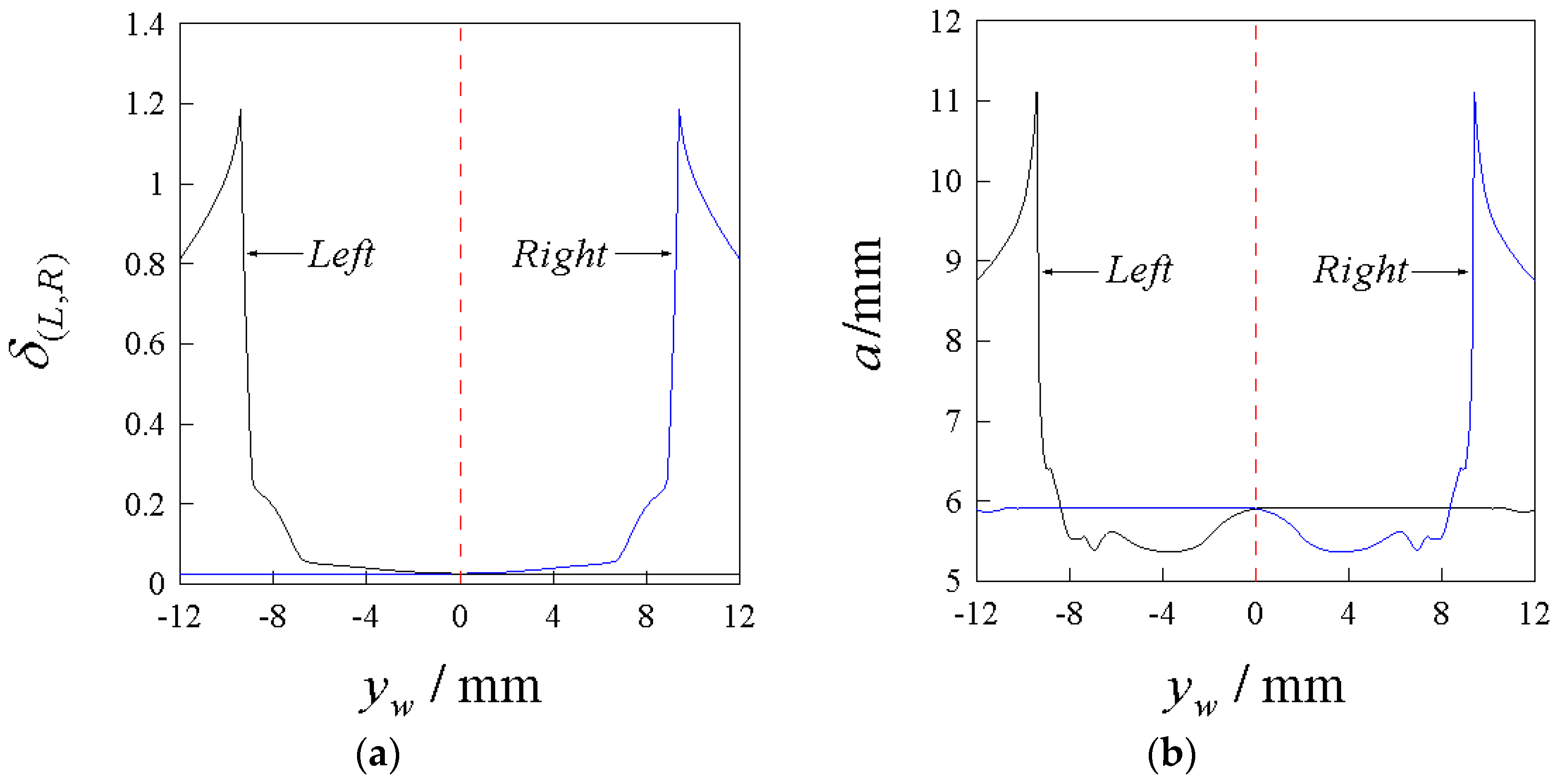
Figure 2 illustrates the contact angle δ(L,R) and minor semi-axes a(L,R) among the wheel–rail contact parameters. It can be observed that the contact angle δ(L,R) is close to the linear relation when the wheelset lateral displacement is small and semi-axes a(L,R) have already exhibited significant nonlinear characteristics. In contrast, larger wheelset lateral displacement exhibits significant nonlinear and non-smooth characteristics, especially after being subjected to the flange force. It can be seen that the linear wheel–rail contact relationship can no longer accurately describe the wheel–rail contact relationship in the severe hunting motion of a vehicle system with worn-type wheels.

2.1.2. The Creep Forces

The relative sliding of the wheelset and the rail between the contact surfaces when the vehicle runs at speed v is called creep. The longitudinal creepage ξ x , lateral creepage ξ y , and rotational creep ξ s p are given by [49]:
ξ ( L , R ) x = v + ψ w y ˙ w + r ( L , R ) ( ψ w ϕ ˙ w Ω ) ± a 0 ψ ˙ w v ξ ( L , R ) y = v ψ w + y ˙ w + r ( L , R ) ϕ ˙ w v cos δ ( L , R ) ξ ( L , R ) s p = ± ( Ω ψ w ϕ ˙ w ) sin δ ( L , R ) + ψ ˙ w δ ( L , R ) v ,
where Ω = v/r0 is the nominal angular velocity. The symbols ± and are assigned as upper signs for the left wheel (L) and lower signs for the right wheel (R). The expressions for creep forces calculated with the Kalker linear creep theory [50] are given by
F x = f 11 ξ x F y = f 22 ξ y f 23 ξ s p M z = f 23 ξ y f 33 ξ s p ,
where f11, f22, f23, f33 represent the longitudinal, lateral, lateral/spin, and spin creep coefficients and can be given by
f 11 = G ( a b ) C 11 f 22 = G ( a b ) C 22 f 23 = G ( a b ) 3 / 2 C 23 f 33 = G ( a b ) 2 C 33 ,
To accommodate large creep, the linear creep force in Equation (2) needs to be revised using the Shen–Hedrick–Elkins method [51]. The revision coefficient ε can be given by
ε = ( β β 2 / 3 + β 3 / 27 ) / β         β 3                               1 / β                                           β > 3 ,
where N stands for normal contact force, and β is expressed as follows
β = F x 2 + F y 2 / ( μ N ) ,
Then, the revised creep forces/torque are
F x = ε F x , F y = ε F y , M z = ε M z .
The revised F x   F y , M z can be converted from the wheel–rail contact patch coordinate system to the track coordinate system. The expression of the coordinate transformation is
F ( L , R ) x F ( L , R ) y M ( L , R ) z = cos ψ w cos ( δ ( L , R ) ± ϕ w ) sin ψ w 0 sin ψ w cos ( δ ( L , R ) ± ϕ w ) cos ψ w 0 0 0 cos ( δ ( L , R ) ± ϕ w ) F ( L , R ) x F ( L , R ) y M ( L , R ) z .

2.1.3. The Normal Contact Forces

In straight track, the vertical part of the normal contact force is half of the axial load W and can be expressed as follows:
N ( L , R ) z = 1 2 W .
The lateral part of the normal contact force is expressed as follows:
N ( L , R ) y = ± N ( L , R ) z tan ( δ ( L , R ) ± ϕ w ) .

2.1.4. The Flange Force

The flange force Ft is represented by a linear spring (with the stiffness k0) incorporating a dead band, which can be described as a piecewise linear function:
F t ( y w ) = k 0 ( y w η ) y w > η 0 y w η k 0 ( y w + η ) y w > η .

2.2. Subsection

The primary suspension forces refer to the forces between the wheelsets and the bogie; the secondary suspension forces are between the bogie and the vehicle body. The suspension forces have three directions: longitudinal, transverse, and vertical.
The primary suspension forces are given by
F x f ( L , R ) i = K 1 x [ ± d w ψ t n d w ψ w i ( 1 ) i 1 d w ( l t R ) ] + C 1 x ± d w ψ ˙ t n d w ψ ˙ w i F y f ( L , R ) i = K 1 y [ Y w i Y t n + H t w ϕ t n + ( 1 ) i l t ψ t n + l t 2 2 R ] + C 1 y Y ˙ w i Y ˙ t n + H t w ϕ ˙ t n + ( 1 ) i l t ψ ˙ t n F z f ( L , R ) i = K 1 z ± d w ϕ w i d w ϕ t + C 1 z ± d w ϕ ˙ w i d w ϕ ˙ t .
The secondary suspension forces are given by
F x t ( L , R ) = K 2 x [ ± d s ψ b d s ψ t ( 1 ) i 1 d s ( l c R ) ] + C 2 x ± d s ψ ˙ b d s ψ ˙ t F y t ( L , R ) = K 2 y Y t i + H b t ϕ t + l c 2 2 R   + C 2 y Y ˙ t i + H b t ϕ ˙ t F z t ( L , R ) = K 2 z ± d s ϕ t + C 2 z ± d s ϕ ˙ t .

2.3. Ordinary Differential Equations of the System

m w y ¨ w i = F y f L i F y f R i + F L y i + F R y i + N L y i + N R y i F t ( y w i ) I w z ψ ¨ w i = a 0 F L x i F R x i + a 0 ψ w i F L y i + N L y i F R y i N R y i                         + M L z i + M R z i + d w ( F x f L i F x f R i ) I w y ϕ ˙ w i Ω m t y ¨ t = F y f L 1 + F y f R 1 + F y f L 2 + F y f R 2 F y t L F y t R I t z ψ ¨ t = l t F y f L 1 + F y f R 1 F y f L 2 F y f R 2 + d w F x f R 1 + F x f R 2 F x f L 1 F x f L 2 d s ( F x t L F x t R ) I t x ϕ ¨ t = h t w F y f L 1 + F y f R 1 + F y f L 2 + F y f R 2 + d w F z f L 1 + F z f L 2 F z f R 1 F z f R 2                   h b t ( F y t L + F y t R ) + d s ( F z t R F z t L ) .
To solve Equation (13), the state vector can be expressed as
Y T = y w 1 , y ˙ w 1 , y w 2 , y ˙ w 2 , ψ w 1 , ψ ˙ w 1 , ψ w 2 , ψ ˙ w 2 , y t , y ˙ t , ψ t , ψ ˙ t , ϕ   t , ϕ ˙   t T ,
where its state space is defined as R 14 = { Y | Y R 14 } .

3. Method of Investigation

3.1. Poincaré Sections

The numerical integration method can calculate the system’s time response. Based on the structural characteristics of the phase trajectory of the hunting motion, to obtain the number of the system’s periods n, we defined Poincaré section Σ1; to obtain the number of impacts p and q of the two wheelsets’ flanges with the left and right side rails, we defined the Poincaré section Σwi (i = 1, 2). The Poincaré section Σ1 is defined by
1 = ( Y , v ) R 14 × V |     y t = 0 ,     y ˙ t > 0 .
The Poincaré section Σwi (i = 1, 2) is defined by
w i = ( Y , v ) R 14 × V |         y w i = η ,     y ˙ w i > 0 ;     y w i = η ,     y ˙ w i < 0 .
where Σw1 and Σw2 correspond to wheel-1 and wheel-2, respectively.

3.2. Two-Parameter Co-Simulation Theory

The two-parameter co-simulation method is developed based on cell mapping, which involves discretizing the state space into multiple cells and determining the final state of each cell by calculating its motion state. This approach enables the calculation of attractors and domains of attraction for the system in the state space. For a single-degree-of-freedom dynamical system, once the state space comprising displacements and velocities is discretized into numerous cells, it becomes possible to calculate the final attributed states of phase trajectories with different initial values of displacements and velocities. However, since a two-dimensional plane can only satisfy two sets of parameters as a state space, there are significant limitations in applying cell mapping to multi-degree-of-freedom dynamical systems.
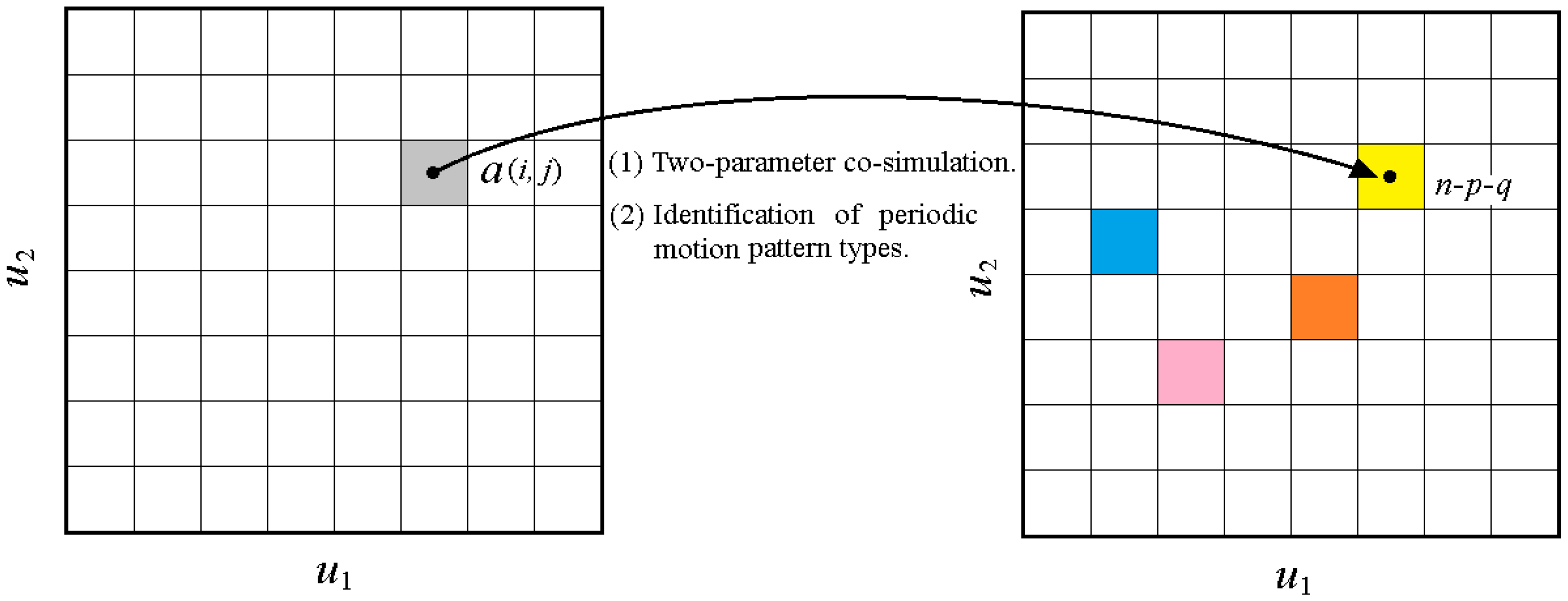
In two-parameter co-simulation, two critical parameters among the system parameters are selected to construct a two-parameter plane. In the schematic diagram of the two-parameter co-simulation method shown in Figure 3, the system parameters u1 and u2 form the (u1, u2)-plane and are discretized into a finite number of grids. The mode of motion at the grid can be determined by calculating the number of periods and impacts of stable phase trajectories under the system parameters at the grid center point a(i, j). The patterns and distributions of period motions on the two-parameter plane can be obtained by identifying each grid’s motion pattern (n-p-q) and marking grids with the same pattern in the same color. The more grid divisions, the smoother and finer the depiction of neighboring periodic motion lines in the (u1, u2)-plane, but computational volume will increase rapidly. In this paper, a 400 × 400 grid was used for calculation. The numerical simulation was conducted on the C++ platform, and the fourth-order Runge–Kutta method was adopted for the numerical solution of the differential equations.

4. Numerical Results and Discussions

4.1. Hunting Motion Patterns and Distribution Regions in the Two-Parameter Plane and Wheel–Rail Impact Characteristics

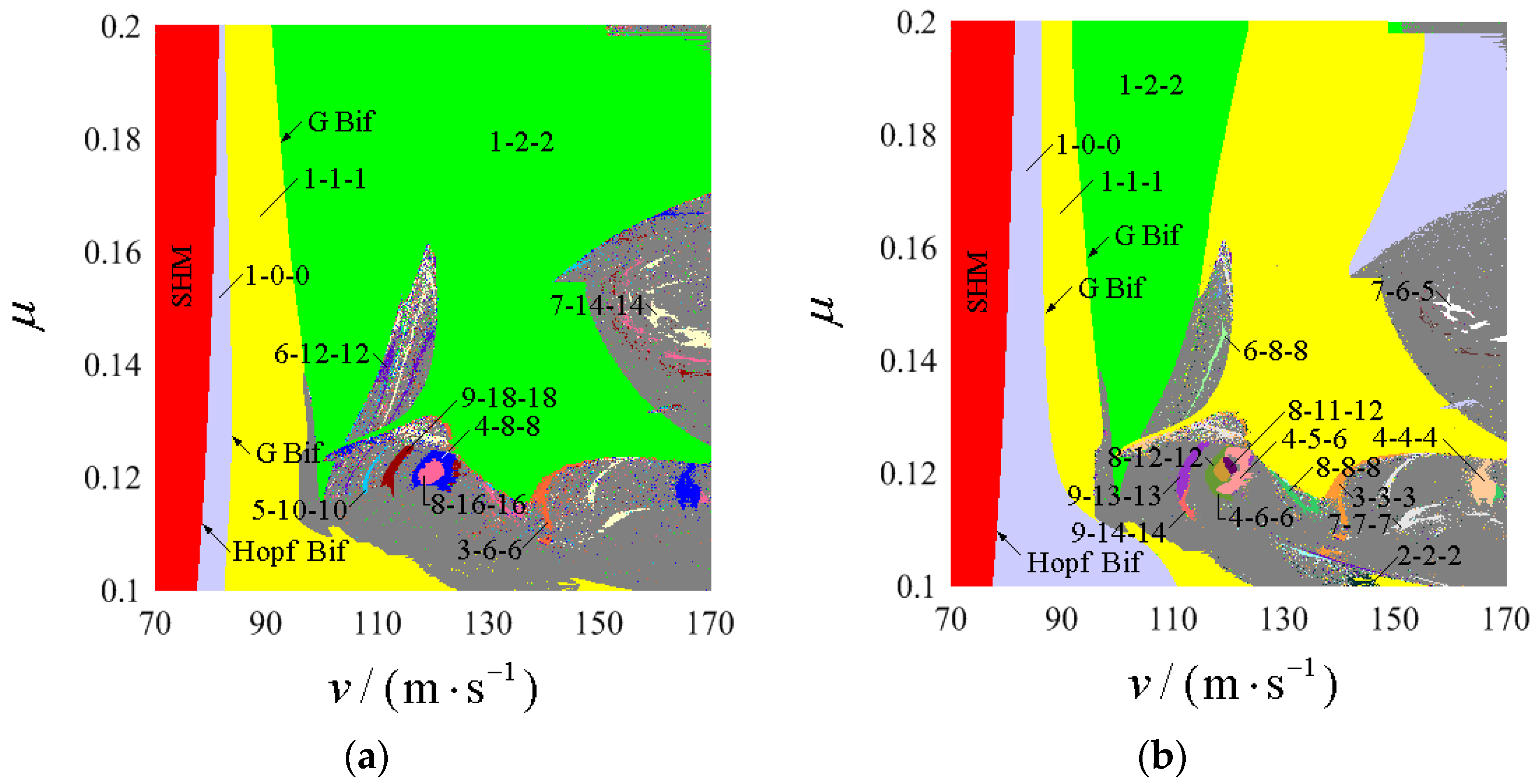
The running speed v is always changed during the operation of a railway vehicle. The railway vehicle service environment is complex, and the temperature, humidity, and wheel–rail medium changes (such as rain, snow, mud, oil, etc.) may make the wheel–rail adhesion coefficient μ change. The select operating speed v and wheel–rail adhesion coefficient μ construct the (v, μ)-plane, where 70 ≤ v ≤ 170 and 0.1 ≤ μ ≤ 0.2. In the numerical simulation, the system is given an initial value Y T = { y w 1 , y ˙ w 1 , y w 2 , y ˙ w 2 , ψ w 1 , ψ ˙ w 1 , ψ w 2 , ψ ˙ w 2 ,   y t , y ˙ t , ψ t , ψ ˙ t , ϕ   t , ϕ ˙   t } T = { 0.009 , 0.04 , 0 , 0 , 0 , 0 , 0 , 0 , 0 , 0 , 0 , 0 , 0 , 0 } T , and the entire parameter plane is scanned line by line with an incremental change in speed v starting from the lower left corner of the entire parameter plane at (v, μ) = (70, 0.1). Based on the computational method of two-parameter co-simulation introduced in Section 3 and the effective identification of the number of cycles and the number of wheel–rail impacts for the hunting motion, the pattern types and existence regions of the hunting motion are obtained in the (v, μ)-planes associated with wheelset-1 and wheelset-2, respectively, as shown in Figure 4. Stable hunting motion (i.e., hunting motion that can converge to the equilibrium point after being disturbed) is expressed by SHM. The periodic hunting motion is represented by n-p-q (n = 1, 2, 3, …; p = 0, 1, 2, 3, …; q = 0, 1, 2, 3, …;); in particular, 1-0-0 represents the periodic hunting motion without wheel–rail impact. The gray area mainly includes chaotic motion, quasi-periodic motion, and periodic hunting motion with minimal area. Partial bifurcation lines are marked in the (v, μ)-plane, where ‘Hopf Bif’ represents Hopf bifurcation and ‘G Bif’ represents grazing bifurcation. The shortened representation also includes the following: ‘SN Bif’ represents saddle-node bifurcation, ‘PD Bif’ represents period-doubling bifurcation, ‘N-S Bif’ represents Neimark–Sacker bifurcation, and ‘PF Bif’ represents pitchfork bifurcation. Figure 5 and Figure 6 show the wheel–rail impact velocity bifurcation diagrams transversely across the (v, μ)-plane for wheelset-1 and wheelset-2, respectively.
In Figure 4, the existence region of SHM (marked in red) is vertically banded and widens with the increase in μ, indicating that the bogie system’s critical speed increases with μ. After that, Hopf bifurcation initiates hunting instability with increasing velocity, and the system enters the hunting motion without wheel–rail impacts (1-0-0). In the same parameter regions, wheelset-1 and wheelset-2 have the same number of periods (the system components coupled to each other have the same number of periods). However, the number of wheel–rail impacts shows significant diversity. For wheelset-1, as seen in Figure 4a, the existence region of the wheel–rail impactless motion 1-0-0 is distributed in a vertical band and narrows significantly with the increase in μ. Notably, 1-0-0 motion is crucial for monitoring hunting stability. Crossing the grazing (G) bifurcation line, the 1-0-0 motion transfers to the 1-1-1 motion. The existence region of 1-1-1 motion extends towards the higher velocity region at smaller μ, shows vertical banding in the larger μ region, and narrows with increasing μ. For smaller μ, the 1-1-1 motion enters chaos directly, as seen in Figure 5a,c, or enters quasi-periodic motion via the Neimark–Sacker bifurcation and then transits to chaotic motion, as seen in Figure 5b. Chaotic and quasi-periodic motions form unidentified grey areas in the larger velocity region. At medium–high μ, the 1-1-1 motion transitions to the 1-2-2 motion through the G bifurcation line. The 1-2-2 motion occupies a substantial domain and extends up to the maximum velocity threshold, as Figure 5d depicts. As v increases, the primary transition process of the hunting motion for wheelset-1 in the (v, μ)-plane can be summarised as follows (bottom-up in the equation is the direction of increasing μ):
v   :   SHM Hopf   Bif 1 - 0 - 0 G   Bif 1 - 1 - 1 G   Bif 1 - 2 - 2                         N - S   Bif           quasi - periodic   motion             or   intermittent   chaos chaotic   motion .
As depicted in Figure 4b, wheelset-2 exhibits a wider velocity range for 1-0-0 motion than wheelset-1, which is more pronounced in the interval of a small μ. This indicates that wheelset-2 experienced wheel–rail impacts later than wheelset-1. This phenomenon can be observed by comparing the lowest velocity at which the bifurcation branches appear in Figure 5a and Figure 6a. At a small μ, chaotic motion dominates the medium-to-high velocity domain, and the periodic to chaotic motion transition law is similar to that in wheelset-1; see Figure 6b,c. In the medium–high interval of μ, the 1-0-0 motion transits to 1-1-1 motion by grazing bifurcation, followed by another grazing bifurcation transition to 1-2-2 motion. As v increases, the 1-2-2 motion migrates to the 1-1-1 motion via the jump bifurcation, and the wheel–rail lateral impact velocity occurs as a jump; see Figure 6d. For wheelset-2, the primary transition process in the (v, μ)-plane can be summarised as follows:
v   :   SHM Hopf   Bif 1 - 0 - 0 G   Bif 1 - 1 - 1 G   Bif 1 - 2 - 2 Jump   Bif 1 - 1 - 1 SN   Bif 1 - 0 - 0                   N - S   Bif           quasi - periodic   motion             or           intermittent   chaos chaotic   motion
Excessive wheel–rail lateral impact velocity may lead to abnormal wheel flange wear, derailment, and other serious accidents. Many scholars focus on the correlation between vehicle operating speed or suspension parameters and wheel–rail lateral impact velocity. Still, the correlation between hunting motion patterns and wheel–rail lateral impact velocity has rarely been investigated. The 3D cloud map and contour map projection of maximum wheel–rail lateral impact velocities associated with wheelset-1 and wheelset-2 are illustrated in Figure 7a and Figure 7b, respectively. Comparing Figure 7a and Figure 7b, it is obvious that wheelset-1 exhibits a significantly higher maximum lateral wheel–rail impact velocity than wheelset-2 across most regions in the parameter plane. Therefore, further research on wheel–rail impact characteristics should focus on wheelset-1. As shown in Figure 7a, the maximum wheel–rail impact velocities of wheelset-1 generally exhibit an increasing trend with the increasing v. The wheel–rail impact velocities in the existence region of 1-1-1 motion and 1-2-2 motion (before jump bifurcation) are relatively small. There are peak regions Z1, Z2, and Z3. Peak region Z1 corresponds to the 1-2-2 motion caused by the amplitude jump of the 1-2-2 motion at low speed; see Figure 5d. The peak regions Z2 and Z3 correspond to the unidentified gray region. It can be seen that the gray regions, which are predominantly characterized by chaotic motion and quasi-periodic motion, are often accompanied by a high wheel–rail impact velocity. For wheelset-2, as seen in Figure 7b, the correlation between the wheel–rail impact velocity and the running speed v is relatively weak. Notably, in the region of 1-1-1 motion, there is a valley with lower wheel–rail impact velocity at middle v. The peak regions Z4 correspond to 1-2-2 motions resulting from amplitude jumps, and the peak regions Z5, Z6, and Z7 also correspond to unidentified gray regions, but their peaks are generally lower.

4.2. Bifurcation and Evolution of Periodic Hunting Motion

The patterns and distribution laws of the periodic motions and the associated maximum wheel–rail impact velocities are obtained by two-parameter co-simulation in Section 4.1. It can be seen that different ranges of μ exhibit different periodic motion patterns and evolution laws. In the range of small μ, select μ = 0.12; in the range of large μ, select μ = 0.18. It utilizes running speed v as the bifurcation parameter to obtain single-parameter bifurcations that cross the (v, μ)-plane laterally and combines time series, phase portraits, and mapping diagrams to reveal further the mechanism of hunting instability as well as the transition and bifurcation laws of the hunting motion. Here, the running speed v is used as the bifurcation parameter to obtain one-parameter bifurcations transversally through the (v, µ)-plane, which is combined with time series, phase diagrams, and mapping diagrams to further reveal the mechanism of hunting instability and the transition and bifurcation laws of hunting motions.

4.2.1. Select μ = 0.12

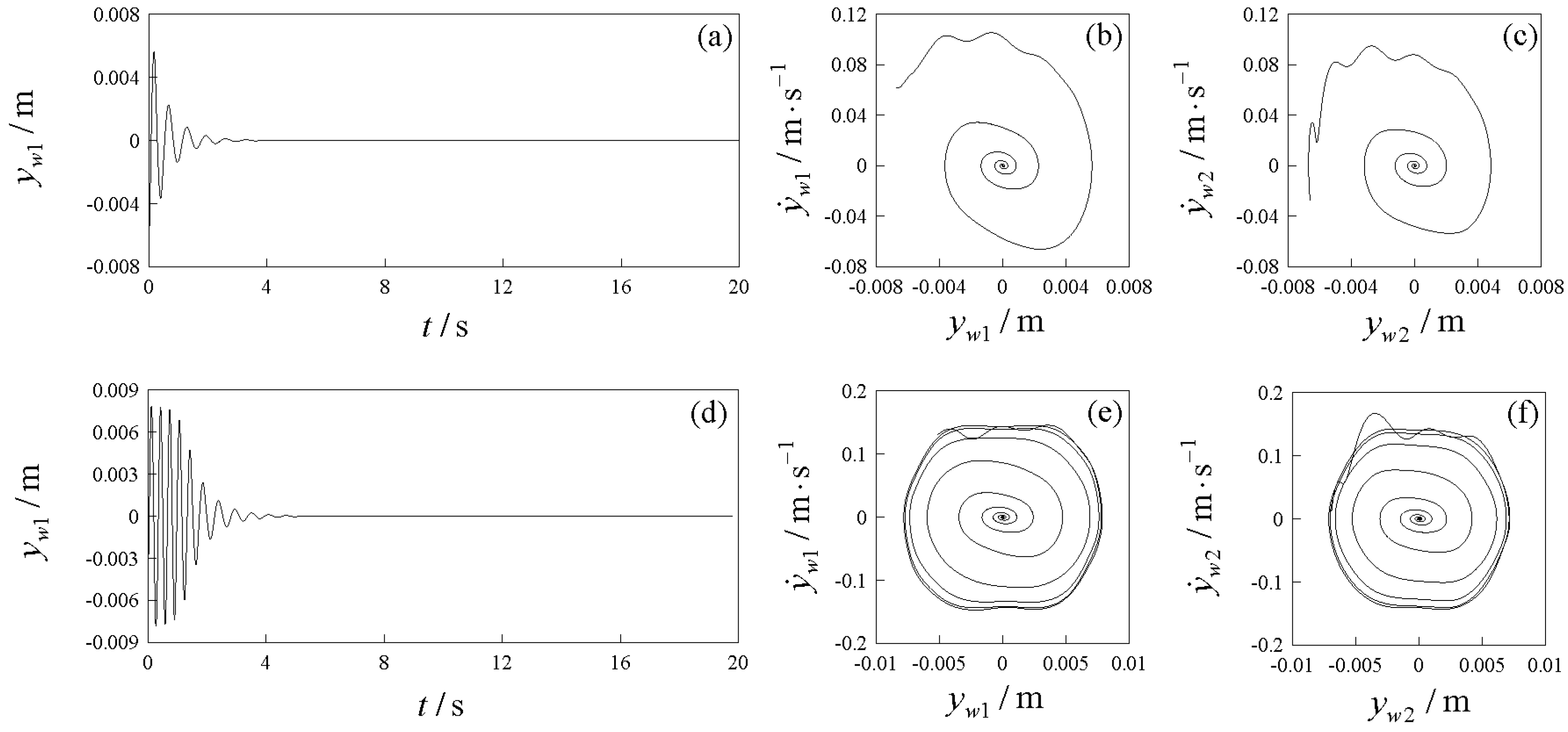
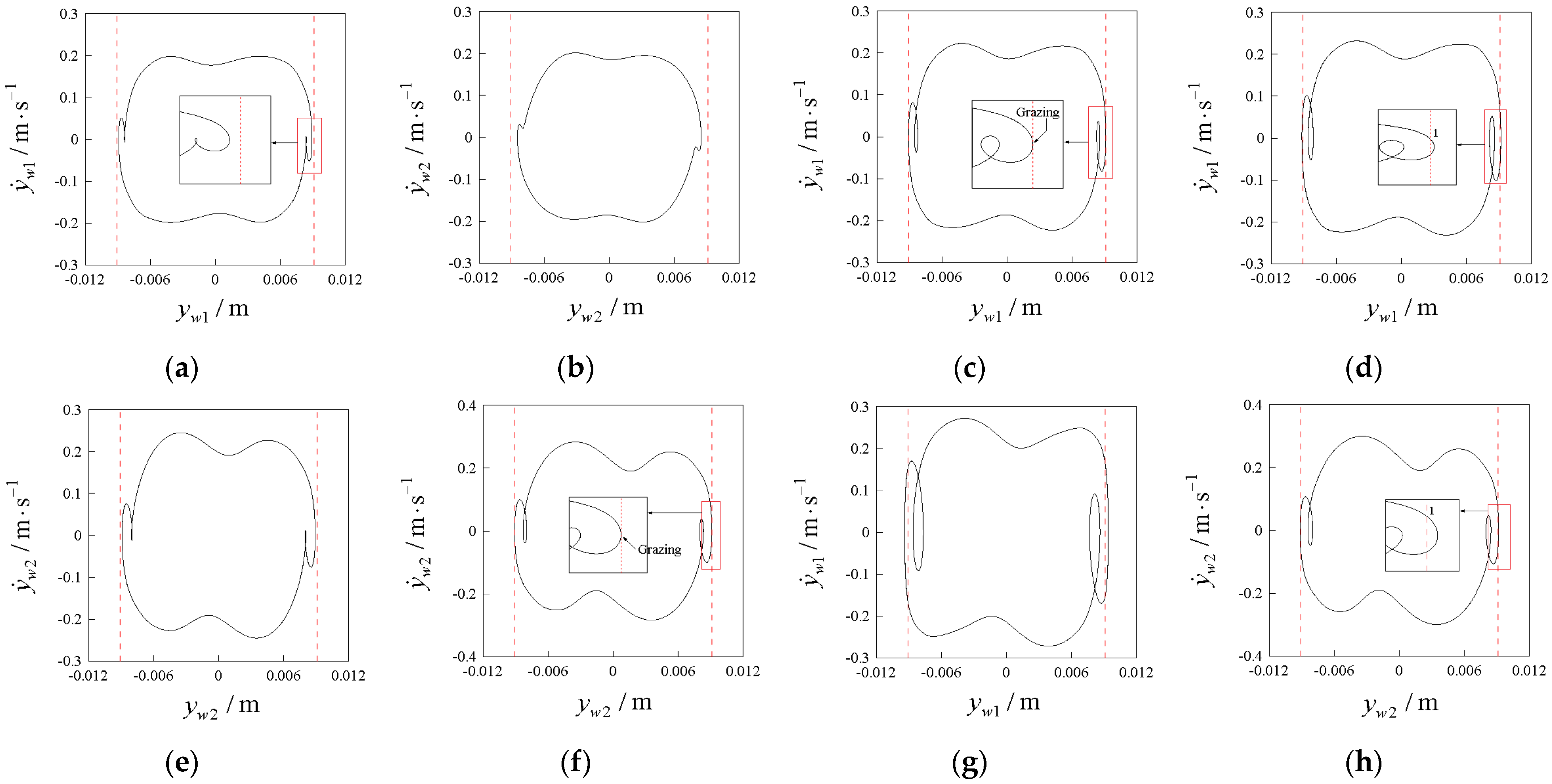
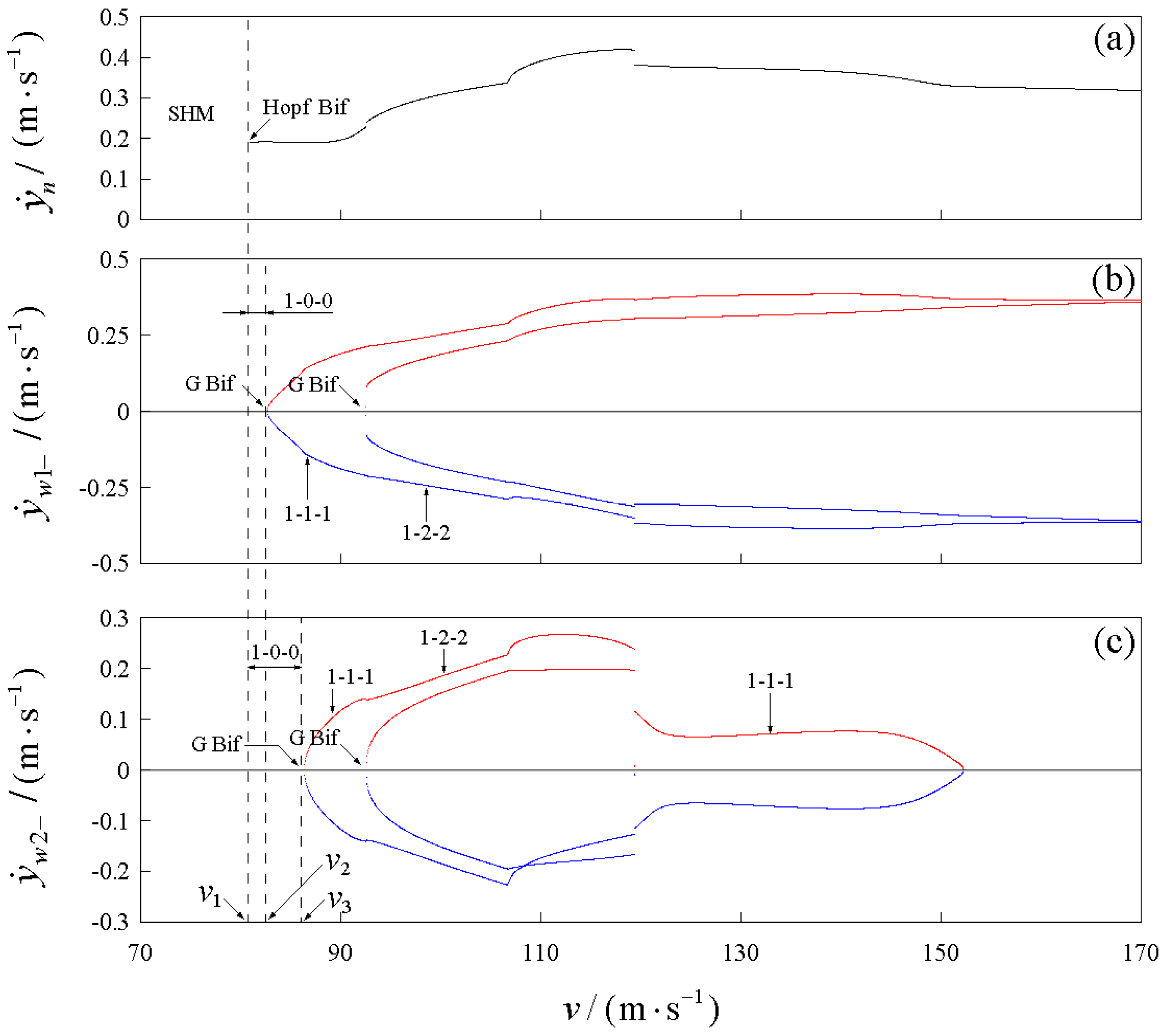
Figure 8 shows the bogie system’s bifurcation diagrams that laterally cross the (v, μ)-plane at μ = 0.12. Figure 8a is the periodic bifurcation diagram based on the period mapping section Σ1. The bifurcation diagram of wheelset-1, based on the wheel–rail impact mapping section Σw1, is depicted in Figure 8b. Meanwhile, the bifurcation diagram of wheelset-2, based on the wheel–rail impact mapping section Σw2, is depicted in Figure 8c. Through numerical simulations, it can be obtained that the critical speed is v1 = 78.8 m/s, the velocity at which wheel–rail impact occurs in wheelset-1 is v2 = 83.45 m/s, and the velocity at which wheel–rail impact occurs in wheelset-2 is v3 = 89.46 m/s. When the operating velocity v is lower than the critical velocity v1, the system is in stable hunting motion and can converge to the stationary solution after external disturbance. Figure 9a,b present the time series and phase portraits of the system converging to the equilibrium point after being subjected to equal external excitations for v = 70 m/s and v = 78 m/s, respectively. It can be found that the convergence of the system slows down significantly when approaching the critical velocity. As v = v1 = 78.8 m/s, the system suffered hunting instability via the Hopf bifurcation, after which the system could not converge to equilibrium after the excitation. Instead, it is in periodic hunting motion. When the running speed slightly exceeds the critical speed in the interval v1 < vv2, the system is in a wheel–rail impact-free hunting motion (1-0-0), as shown in Figure 10a,b. When v = v2 = 83.45 m/s, wheelset-1 is in 1-0-0 motion with grazing, as depicted in Figure 10c. Grazing motion is a motion state in which the velocity is infinitely close to zero when the displacement reaches the constraint boundary, and it is a typical non-smooth bifurcation that exists only in non-smooth systems. After grazing bifurcation, wheelset-1 exhibits the 1-1-1 motion in Figure 10d, while wheelset-2 experiences delayed wheel–rail impact compared to wheelset-1 and maintains the 1-0-0 motion, as illustrated in Figure 10d,e. At v = v3 = 89.46 m/s, wheelset-2 exhibits the 1-0-0 motion with grazing, as depicted in Figure 10f. After that, both wheelsets are in 1-1-1 motion involving wheel–rail impacts; see Figure 10g,h.
As v increases, it is accompanied by more complex periodic motion patterns and multiple bifurcation types. When v = 95.6 m/s, the system suffers the Neimark–Sacker bifurcation, and the two wheelsets go from the 1-1-1 motion to the quasi-period 1-1-1 motion. Figure 11a,b shows the phase diagrams of the two wheelsets at v = 96 m/s. The phase trajectory of quasi-periodic motion exhibits a closed black band. When v = 97.25 m/s, the quasi-period 1-1-1 motion of wheelset-1 grazes with the rail, as seen in Figure 11c, and wheelset-2 is in quasi-period 1-1-1 motion, as seen in Figure 11d. After G bifurcation, wheelset-1 enters chaotic motion with two attractors, and wheelset-2 enters chaotic motion with one attractor; see Figure 11e,f. Afterward, the two wheelsets degenerate from chaotic to 1-2-2 motion and then enter quasi-period motion again through Neimark–Sacker bifurcation, followed by chaotic motion over a more extended velocity range. It can be observed that there are many subharmonic motion windows embedded in the chaotic motion velocity intervals. We focus on analyzing the properties of the subharmonic motion windows embedded in the velocity interval v ∈ [110, 126] m/s. Figure 12 shows the combined bifurcation diagrams obtained with the numerical simulation with increasing and decreasing running speeds, respectively (the black and magenta bifurcation branches correspond to the numerical simulation results for increasing(vZ) and decreasing(vb) velocities, respectively). The objective is to further reveal the possible coexistence behavior of periodic hunting motions. It can be observed that there are two subharmonic motion windows in the velocity range v ∈ [110, 126] m/s. In the first window of subharmonic motion at a low speed, the number of periods of the system is n = 9, which can be obtained from the number of branches of the period bifurcation diagrams shown in Figure 12a; wheelset-1 is in subharmonic hunting motion 9-18-18, wheelset-2 is in subharmonic hunting motion 9-13-13, and the number of wheel–rail impacts can be obtained from the branch numbers of the impact velocity bifurcation diagrams in Figure 12b and Figure 12c, respectively. It should be emphasized that the subharmonic motions in this periodic window are symmetric, so there is no coexistence of periodic motions. The hunting motion patterns in the other subharmonic motion window in the higher velocity range are more complex, containing asymmetric subharmonic motions and coexistence behavior due to initial value sensitivity. In Figure 12a, it can be observed that the number of periods of subharmonic motion generated by the period-doubling bifurcation is n = 4, n = 8, and n = 16, and the black bifurcation branches (numerical simulation with vZ) and magenta bifurcation branches (numerical simulation with vb) coexist. For wheelset-1, it can be observed in Figure 12b that periodic doubling bifurcation sequences generate subharmonic motions (4-8-8, 8-16-16, and 16-32-23). As seen in Figure 12c, for wheelset-2, there are not only subharmonic motions (4-6-6, 8-12-12, and 16-24-24) generated by periodic doubling bifurcation sequences. At the same time, there are more complex motion patterns caused by G and SN bifurcations.
After exiting the velocity range of chaotic motion, the two wheelsets enter the 1-2-2 motion, as shown in Figure 13(a1,a2). As the speed increases, the 1-2-2 motion transitions from Neimark–Sacker bifurcation to the quasi-periodic motion, and the number of quasi-periodic motion attractors remains consistent with the number of periodic attractors; see in Figure 13(b1,b2).

4.2.2. Select μ = 0.18

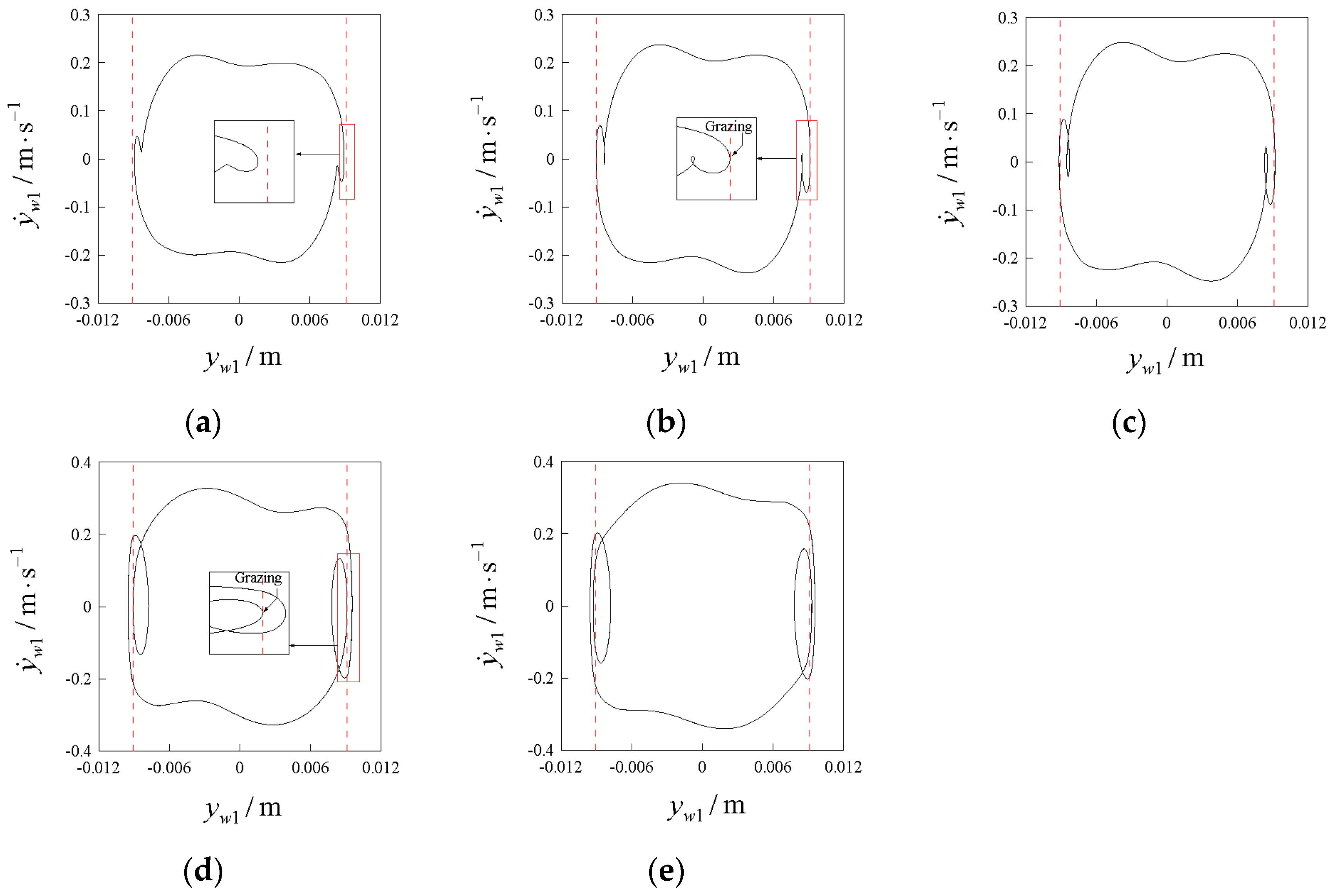
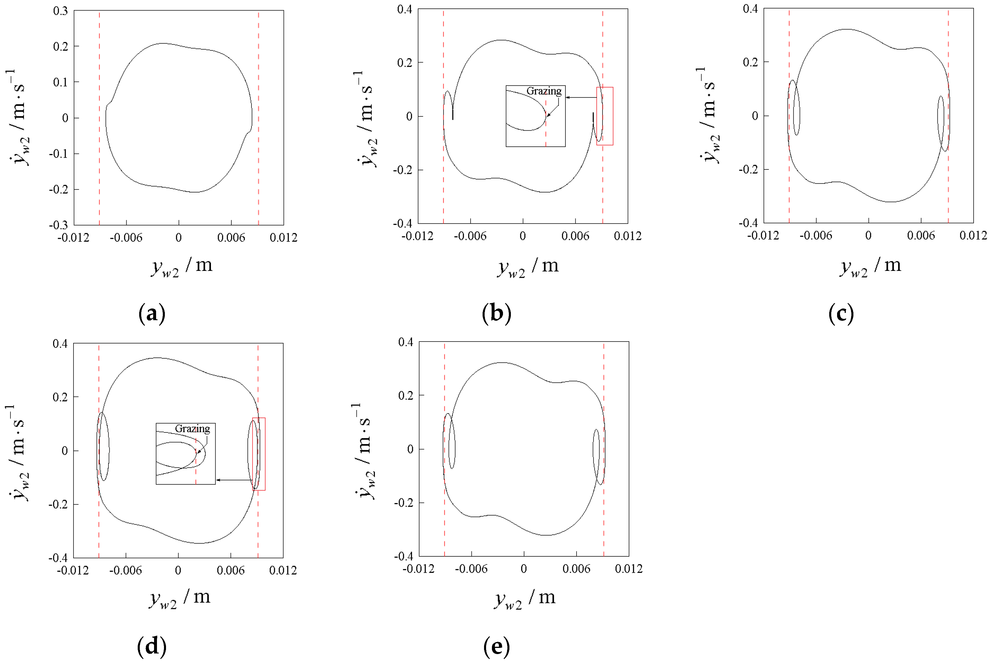
The bifurcation diagrams of the bogie system that laterally crosses the (v, μ)-plane at μ = 0.18 are shown in Figure 14, in which v1 = 78.8 m/s, v2 = 82.7 m/s, and v3 = 86.4 m/s. Compared to the one-parameter bifurcation diagram in Figure 8 at µ = 0.12, for low v, the most remarkable difference is that both wheelsets undergo two sequential G bifurcations, thus entering the 1-2-2 motion. When v1 < vv2, wheelset-1 is in the 1-0-0 motion. When v = v2 = 82.7 m/s, it enters 1-1-1 motion through the first G bifurcation. When v = 92.55 m/s, it enters 1-2-2 motion through the second G bifurcation. The phase diagram of the transition process is shown in Figure 15a–e. Similarly, Figure 16a–e describes the transmigration for wheelset-2 from the 1-0-0 to the 1-2-2 motion via two G bifurcations. The first G bifurcation occurs at v = v3 = 86.4 m/s, and the second G bifurcation occurs at v = v3 = 92.6 m/s. It can be seen that wheelset-2 undergoes G bifurcation later than wheelset-1.
It can be observed that the 1-2-2 motions of two wheelsets show asymmetric branches and amplitude jumps in the medium velocity interval. Figure 17 presents the combined bifurcation diagrams in the velocity interval v ∈ [110, 126] m/s, and the black and magenta bifurcation branches correspond to the numerical simulation results for increasing (vZ) and decreasing (vb) velocities, respectively. The different-colored bifurcation diagram branches between pitchfork (PF) bifurcation point A and jump (J) bifurcation point B are caused by the asymmetry caused by PF bifurcation, which are coexisting periodic solutions under different initial conditions. Figure 18(a1,a2) shows the phase diagram of coexisting periodic solutions of 1-2 motion (in black) and 1-2 motion (in magenta) of two wheelsets at v = 113 m/s. It can be observed that the two coexisting periodic solutions are symmetric about the center of the coordinate origin. Between J bifurcation point B and J bifurcation point C, there is a coexistence of periodic motions due to amplitude jumps initiated by J bifurcation. For wheelset-1, J bifurcation only leads to amplitude jumps, and the motion mode remains 1-2-2 motion. Figure 18(b1) shows the coexistence of 1-2-2 motion (in black) and 1-2-2 motion (in magenta) at v =122 m/s. For wheelset-2, as the speed increases, 1-2-2 motion jumps to 1-1-1 motion. When the velocity decreases, 1-1-1 motion jumps to 1-2-2 motion. Thus, in this velocity interval, 1-1-1 motion (in black) and 1-2-2 motion (in magenta) coexist; see Figure 18(b2). Importantly, PF bifurcation or G bifurcation leads to the coexistence of multiple period motions. The different initial states will cause the system to have different periodic motion patterns. The constant change in environmental excitations in actual working conditions may cause the system to switch repeatedly between multiple coexisting motions, leading to abnormal vibration, increased wear, and so on.

5. Conclusions

A lateral dynamic model of the 7-DOFs bogie system is constructed, in which the nonlinear, non-smooth wheel–rail contact relations and the piecewise linear flange force make it a typical non-smooth dynamic system. Based on Poincaré mapping theory and two-parameter simulation, patterns and distributions of hunting motions are accurately identified and depicted in the (v, μ)-plane, and 3D cloud maps of the maximum lateral wheel–rail impact velocity are obtained.
In the (v, μ)-plane, for low v, the pattern types of periodic hunting motions are relatively simple and appear as vertical band distributions. As μ increases, the critical speed of the bogie system increases accordingly, and the regions of 1-0-0 and 1-1-1 motions are significantly narrowed. Among them, wheel–rail impactless motion 1-0-0 is vital in detecting hunting instability. For high v, the change in μ initiates significant changes in the type of periodic motion patterns, accompanied by the emergence of subharmonic and chaotic motions.
The maximum lateral wheel–rail impact velocities of wheelset-1 are generally higher than those of wheelset-2, and the overall trend of wheel–rail impact velocities increases with the increasing v. The correlations between the lateral wheel–rail impact velocities and the patterns of hunting motions were found. The 1-1-1 motion was associated with the low maximum lateral wheel–rail impact velocities. In contrast, unidentified gray areas (dominated by chaotic motions and part of subharmonic motions) commonly corresponded to the peak regions.
The bifurcations and the evolution of periodic hunting motions are further revealed by selecting μ = 0.12 and μ = 0.18 within typical parameter intervals, respectively. The Hopf bifurcation initiated the hunting instability of the bogie system, and the grazing bifurcation initially caused the wheel–rail impact. Based on the combined bifurcation diagram, it is observed that the subharmonic motions in specific periodic motion windows exhibit symmetry, so there is no coexistence of periodic motions. Conversely, within some subharmonic motion windows, the coexistence behavior of periodic motion is caused by pitchfork bifurcation. The coexisting periodic solutions with different initial values belong to two symmetric branches of pitchfork bifurcation. At the same time, the pitchfork bifurcation caused asymmetric impact velocities between the wheelset and the two sides of the rail. At higher speed intervals, jump bifurcation causes wheel–rail impact velocities’ amplitude jumps and produces a coexistence behavior of periodic motions.
Based on the numerical simulation, the bogie system exhibits abundant periodic hunting motion patterns when operating above the critical speed and correlation between the pattern types and the wheel–rail impact characteristics. The coexisting behavior of periodic hunting motions in some speed intervals could initiate abnormal vibrations and increased wear. The two-parameter co-simulation research method used in this paper can provide some theoretical guidance for the prediction of hunting motion patterns and the parameter design and selection of a bogie system. As wheel–rail impacts occur at speeds higher than critical speeds, relevant experimental validation is seldom found to be carried out. Therefore, the validation of the effectiveness of numerical simulations still needs to be realized in subsequent studies.

Author Contributions

Conceptualization, S.W.; methodology, S.W.; software, L.M. and L.Z.; formal analysis, S.W.; investigation, L.M. and L.Z.; writing–original draft preparation, S.W. All authors have read and agreed to the published version of the manuscript.

Funding

This study was funded by the Gansu Science and Technology Planning Project (No. 22JR5RA340), the Guangxi Young and Middle-aged Teachers’ Research Ability Foundation project (No. 2024KY0806), and the Young Scholars Science Foundation of Lanzhou Jiaotong University (No. 2022049).

Institutional Review Board Statement

Not applicable.

Informed Consent Statement

Not applicable.

Data Availability Statement

The data that support the findings of this study are available upon reasonable request from the corresponding authors. The data are not publicly available due to privacy.

Conflicts of Interest

The authors declare no conflicts of interest.

References

  1. Lee, H.; Sandu, C.; Holton, C. Dynamic Model for the Wheel–Rail Contact Friction. Veh. Syst. Dyn. 2012, 50, 299–321. [Google Scholar] [CrossRef]
  2. Knothe, K.; Böhm, F. History of Stability of Railway and Road Vehicles. Veh. Syst. Dyn. 1999, 31, 283–323. [Google Scholar] [CrossRef]
  3. Matsui, N. A Practical Calculation Method of Quasi-Static Curving Performance of Railway Bogie Vehicles. Veh. Syst. Dyn. 1979, 8, 152–157. [Google Scholar] [CrossRef]
  4. Scheffel, H. The Influence of the Suspension on the Hunting Stability of Railways. Rail Int. 1979, 10, 662–696. [Google Scholar]
  5. Wickens, A.H. The Dynamic Stability of Railway Vehicle Wheelsets and Bogies Having Profiled Wheels. Int. J. Solids Struct. 1965, 1, 319–341. [Google Scholar] [CrossRef]
  6. Wickens, A.H. Paper 1: The Dynamics of Railway Vehicles on Straight Track: Fundamental Considerations of Lateral Stability. Proc. Inst. Mech. Eng. Conf. Proc. 1965, 180, 29–44. [Google Scholar] [CrossRef]
  7. Cooperrider, N.K. The Hunting Behavior of Conventional Railway Trucks. J. Eng. Ind. 1972, 94, 752–761. [Google Scholar] [CrossRef]
  8. Huilgol, R.R. Hopf-Friedrichs Bifurcation and the Hunting of a Railway Axle. Quart. Appl. Math. 1978, 36, 85–94. [Google Scholar] [CrossRef]
  9. Xu, G.; Steindl, A.; Troger, H. Nonlinear Stability Analysis of a Bogie of a Low-platform Wagon. Veh. Syst. Dyn. 1992, 20, 653–665. [Google Scholar] [CrossRef]
  10. Ahmadian, M.; Yang, S.P. Hopf Bifurcation and Hunting Behavior in a Rail Wheelset with Flange Contact. Nonlinear Dyn. 1997, 15, 15–30. [Google Scholar] [CrossRef]
  11. Zeng, J.; Zhang, W.H.; Dai, H.Y. Hunting Instability Analysis and H ∞ Controlled Stabilizer Design for High Speed Railway Passenger Car. Veh. Syst. Dyn. 1998, 29, 655–668. [Google Scholar] [CrossRef]
  12. Zeng, J.; Zhang, J.; Shen, Z.Y. Hopf Bifurcation and Nonlinear Oscillations in Railway Vehicle Systems. Veh. Syst. Dyn. 1999, 33, 552–565. [Google Scholar] [CrossRef]
  13. Wagner, U. Nonlinear dynamic behaviour of a railway wheelset. Veh. Syst. Dyn. 2009, 47, 627–640. [Google Scholar] [CrossRef]
  14. Dong, H.; Zhao, B.; Deng, Y. Instability Phenomenon Associated with Two Typical High Speed Railway Vehicles. Int. J. Nonlinear Mech. 2018, 105, 130–145. [Google Scholar] [CrossRef]
  15. Yan, Y.; Zeng, J. Hopf Bifurcation Analysis of Railway Bogie. Nonlinear Dyn. 2018, 92, 107–117. [Google Scholar] [CrossRef]
  16. Guo, P.; Huang, C.; Zeng, J.; Cao, H. Hopf–Hopf Bifurcation Analysis Based on Resonance and Non-Resonance in a Simplified Railway Wheelset Model. Nonlinear Dyn. 2022, 108, 1197–1215. [Google Scholar] [CrossRef]
  17. Kaas-Petersen, C.; True, H. Periodic, Biperiodic and Chaotic Dynamical Behaviour of Railway Vehicles. Veh. Syst. Dyn. 1986, 15, 208–221. [Google Scholar] [CrossRef]
  18. True, H. Railway Vehicle Chaos and Asymmetric Hunting. Veh. Syst. Dyn. 1992, 20, 625–637. [Google Scholar] [CrossRef]
  19. True, H.; Jensen, J.C. Parameter Study of Hunting and Chaos in Railway Vehicle Dynamics. Veh. Syst. Dyn. 1994, 23, 508–521. [Google Scholar] [CrossRef]
  20. Isaksen, P.; True, H. On the Ultimate Transition to Chaos in the Dynamics of Cooperrider’s Bogie. Chaos Solitons Fractals 1997, 8, 559–581. [Google Scholar] [CrossRef]
  21. True, H. On the Theory of Nonlinear Dynamics and Its Applications in Vehicle Systems Dynamics. Veh. Syst. Dyn. 1999, 31, 393–421. [Google Scholar] [CrossRef]
  22. Gao, X.J.; Li, Y.H.; Gao, Q. Lateral Bifurcation Behavior of a Four-Axle Railway Passenger Car. J. Appl. Mech. 2010, 77, 061001. [Google Scholar] [CrossRef]
  23. Gao, X.J.; Li, Y.H.; Yue, Y. The “Resultant Bifurcation Diagram” Method and Its Application to Bifurcation Behaviors of a Symmetric Railway Bogie System. Nonlinear Dyn. 2012, 70, 363–380. [Google Scholar] [CrossRef]
  24. Gao, X.J. Symmetric/Asymmetric Bifurcation Analysis of Railway Bogie System under Complex Nonlinear Wheel-rail Contact Relation. JME 2013, 49, 129–135. [Google Scholar] [CrossRef]
  25. Gao, X.J.; Li, Y.H.; Yue, Y.; True, H. Symmetric/Asymmetric Bifurcation Behaviours of a Bogie System. J. Sound Vib. 2013, 332, 936–951. [Google Scholar]
  26. Bustos, A.; Tomas-Rodriguez, M.; Rubio, H.; Castejon, C. On the Nonlinear Hunting Stability of a High-Speed Train Bogie. Nonlinear Dyn. 2023, 111, 2059–2078. [Google Scholar] [CrossRef]
  27. Zboinski, K.; Dusza, M. Self-Exciting Vibrations and Hopf’s Bifurcation in Nonlinear Stability Analysis of Rail Vehicles in a Curved Track. Eur. J. Mech.—A/Solids 2010, 29, 190–203. [Google Scholar] [CrossRef]
  28. Zboinski, K.; Dusza, M. Extended Study of Railway Vehicle Lateral Stability in a Curved Track. Veh. Syst. Dyn. 2011, 49, 789–810. [Google Scholar] [CrossRef]
  29. Wei, L.; Zeng, J.; Chi, M.R.; Wang, J.B. Carbody Elastic Vibrations of High-Speed Vehicles Caused by Bogie Hunting Instability. Veh. Syst. Dyn. 2017, 55, 1321–1342. [Google Scholar] [CrossRef]
  30. Li, W.; Guan, Q.; Chi, M.; Wen, Z.F.; Sun, J.F. An Investigation into the Influence of Wheel–Rail Contact Relationships on the Carbody Hunting Stability of an Electric Locomotive. Proc. Inst. Mech. Eng. Part F J. Rail Rapid Transit 2022, 236, 1198–1209. [Google Scholar] [CrossRef]
  31. Chang, C.; Ding, X.; Ling, L.; Li, F.S.; Liu, T.; Wang, K.Y.; Zhai, W.M. Mechanism of High-Speed Train Carbody Shaking Due to Degradation of Wheel-Rail Contact Geometry. Int. J. Rail Transp. 2023, 11, 289–316. [Google Scholar] [CrossRef]
  32. Jensen, C.N.; True, H. On a New Route to Chaos in Railway Dynamics. Nonlinear Dyn. 1997, 13, 117–129. [Google Scholar] [CrossRef]
  33. Evans, J.; Berg, M. Challenges in Simulation of Rail Vehicle Dynamics. Veh. Syst. Dyn. 2009, 47, 1023–1048. [Google Scholar] [CrossRef]
  34. Kim, P.; Seok, J. Bifurcation Analysis on the Hunting Behavior of a Dual-Bogie Railway Vehicle Using the Method of Multiple Scales. J. Sound Vib. 2010, 329, 4017–4039. [Google Scholar] [CrossRef]
  35. Miao, P.C.; Li, D.H.; Chen, H.B.; Yue, Y.; Xie, J.H. Generalized Hopf Bifurcation of a Non-Smooth Railway Wheelset System. Nonlinear Dyn. 2020, 100, 3277–3293. [Google Scholar] [CrossRef]
  36. Li, J.H.; Cui, N. Bifurcation, Geometric Constraint, Chaos, and Its Control in a Railway Wheelset System. Math. Methods Appl. Sci. 2023, 46, 7311–7332. [Google Scholar] [CrossRef]
  37. Ge, P.H.; Wei, X.K.; Liu, J.Z.; Cao, H.J. Bifurcation of a Modified Railway Wheelset Model with Nonlinear Equivalent Conicity and Wheel–Rail Force. Nonlinear Dyn. 2020, 102, 79–100. [Google Scholar] [CrossRef]
  38. Guo, J.Y.; Shi, H.L.; Luo, R.; Zeng, J. Bifurcation Analysis of a Railway Wheelset with Nonlinear Wheel–Rail Contact. Nonlinear Dyn. 2021, 104, 989–1005. [Google Scholar] [CrossRef]
  39. Charles, G.; Dixon, R.; Goodall, R. Least Squares Method Applied to Rail Vehicle Contact Condition Monitoring. IFAC Proc. Vol. 2008, 41, 7451–7456. [Google Scholar] [CrossRef]
  40. True, H.; Engsig-Karup, A.P.; Bigoni, D. On the Numerical and Computational Aspects of Non-Smoothnesses That Occur in Railway Vehicle Dynamics. Math. Comput. Simul. 2014, 95, 78–97. [Google Scholar] [CrossRef]
  41. Gao, X.J.; True, H.; Li, Y.H. Lateral Dynamic Features of a Railway Vehicle. Proc. Inst. Mech. Eng. Part F J. Rail Rapid Transit 2016, 230, 909–923. [Google Scholar] [CrossRef]
  42. Zhang, T.T.; Dai, H.Y. On the Nonlinear Dynamics of a High-Speed Railway Vehicle with Non-smooth Elements. Appl. Math. Model. 2019, 76, 526–544. [Google Scholar] [CrossRef]
  43. Zhang, T.T.; True, H.; Dai, H.Y. A Codimension Two Bifurcation in a Railway Bogie System. Arch. Appl. Mech. 2018, 88, 391–404. [Google Scholar] [CrossRef]
  44. Luo, G.W.; Shi, Y.Q.; Zhu, X.F.; Du, S.S. Hunting Patterns and Bifurcation Characteristics of a Three-Axle Locomotive Bogie System in the Presence of the Flange Contact Nonlinearity. Int. J. Mech. Sci. 2018, 136, 321–338. [Google Scholar] [CrossRef]
  45. Dong, H.; Zeng, J.; Xie, J.H.; Jia, L. Bifurcation/instability Forms of High Speed Railway Vehicles. Sci. China Technol. Sci. 2013, 56, 1685–1696. [Google Scholar] [CrossRef]
  46. Zhang, T.T.; Dai, H.Y. Loss of Stability of a Railway Wheelset, Subcritical or Supercritical. Veh. Syst. Dyn. 2017, 55, 1731–1747. [Google Scholar] [CrossRef]
  47. Wang, P.; Yang, S.P.; Liu, Y.Q.; Liu, P.F.; Zhang, X.; Zhao, Y.W. Research on Hunting Stability and Bifurcation Characteristics of Nonlinear Stochastic Wheelset System. Appl. Math. Mech.-Engl. Ed. 2023, 44, 431–446. [Google Scholar] [CrossRef]
  48. Kik, W. Comparison of the behaviour of different wheelset-track models. Veh. Syst. Dyn. 1992, 20, 325–339. [Google Scholar] [CrossRef]
  49. Hoffmann, M.; Petersen, D.E. Curving Dynamics of Railway Vehicles; Technical Report; Department of Mathematical Modelling, Technical University of Denmark: Kongens Lyngby, Denmark, 2002. [Google Scholar]
  50. Kalker, J.J. A fast algorithm for the simplified theory of rolling contact. Veh. Syst. Dyn. 1982, 11, 1–13. [Google Scholar] [CrossRef]
  51. Shen, Z.Y.; Hedrick, J.K.; Elkins, J.A. A comparison of alternative creep force models for rail vehicle dynamic analysis. Veh. Syst. Dyn. 1983, 12, 79–83. [Google Scholar] [CrossRef]
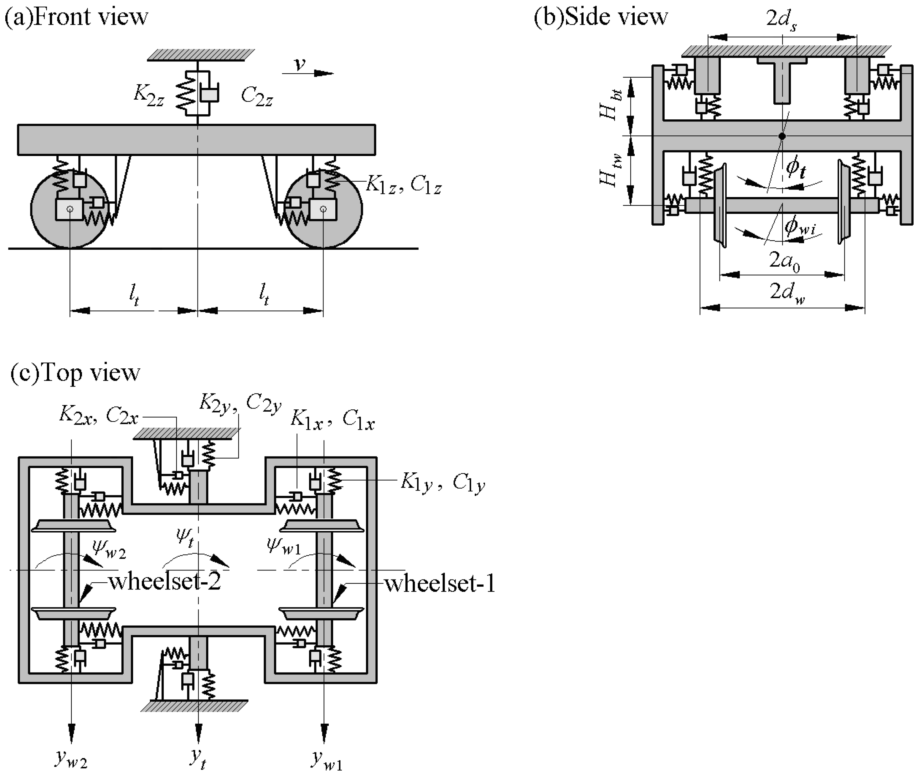
Figure 1. A schematic diagram of the lateral dynamic model.
Applsci 14 05492 g001
Figure 2. The data tables of (a) the contact angle δ(L,R); (b) minor semi-axes a(L,R).
Applsci 14 05492 g002
Figure 3. Theory of two-parameter co-simulation.
Applsci 14 05492 g003
Figure 4. Hunting motion patterns and distribution of two wheelsets in (v, μ)-plane. (a) wheelset-1; (b) wheelset-2.
Applsci 14 05492 g004
Figure 5. The wheelset–rail impact velocity bifurcation diagrams of wheelset-1 that laterally cross the (v, μ)-plane with the following μ: (a) 0.1; (b) 0.12; (c) 0.14; (d) 0.18. (The red and blue bifurcation branches correspond to right and left side wheel–rail impacts, respectively.).
Applsci 14 05492 g005
Figure 6. The wheelset–rail impact velocity bifurcation diagrams of wheelset-2 that laterally cross the (v, μ)-plane with the following μ: (a) 0.1; (b) 0.12; (c) 0.14; (d) 0.18.
Applsci 14 05492 g006
Figure 7. Three-dimensional cloud map and projection of contour map of maximum wheel–rail impact velocities. (a) wheelset-1; (b) wheelset-2.
Applsci 14 05492 g007
Figure 8. Bifurcation diagrams that laterally cross the (v, μ)-plane at μ = 0.12. (a) The period mapping section Σ1; (b) the wheel–rail impact mapping section Σw1 of wheel-1; (c) the wheelset–rail impact mapping section Σw2 of wheel-2. (The red and blue bifurcation branches correspond to right and left side wheel–rail impacts, respectively).
Applsci 14 05492 g008
Figure 9. Time series and phase portraits of wheelset-1 and wheelset-2. (ac) v = 70 m/s; (df) v = 78 m/s.
Applsci 14 05492 g009
Figure 10. Phase portraits of two wheelsets. (a,b) v = 80m/s, wheelset-1 and wheelset-2, 1-0-0 motion; (c) v = 83.45 m/s, wheelset-1, 1-0-0 motion with grazing; (d) v = 85 m/s, wheelset-1, 1-1-1 motion; (e) v = 85 m/s, wheelset-2, 1-0-0 motion; (f) v = 89.46 m/s, wheelset-2, 1-0-0 motion with grazing; (g,h) v = 92 m/s, wheelset-1 and wheelset-2, 1-1-1 motion.
Applsci 14 05492 g010
Figure 11. Phase portraits. (a,b) v = 96 m/s, quasi-period 1-1-1 motion of two wheelsets; (c,d) v = 97.25 m/s, quasi-period 1-1-1 motion of wheelset-1 grazing with rail and quasi-period 1-1-1 motion of wheelset-2; (e,f) v = 97.5 m/s, chaos motion of two wheelsets.
Applsci 14 05492 g011
Figure 12. Combined bifurcation diagrams in the speed range v ∈ [110, 126] m/s. (a) The period mapping section Σ1; (b) the wheelset–rail impact mapping section Σw1; (c) the wheelset–rail impact mapping section Σw2. (The black and magenta bifurcation branches correspond to the numerical simulation results for increasing(vZ) and decreasing(vb) velocities, respectively).
Applsci 14 05492 g012
Figure 13. Phase portraits of two wheelsets. (a1) v =135 m/s, wheelset-1, 1-2-2 motion; (a2) v =135 m/s, wheelset-2, 1-1-1 motion; (b1) v =170 m/s, wheelset-1, quasi-period 1-2-2 motion; (b2) v =170 m/s, wheelset-2, quasi-period 1-1-1 motion.
Applsci 14 05492 g013
Figure 14. Bifurcation diagrams that laterally cross the (v, μ)-plane at μ = 0.18. (a) The period mapping section Σ1; (b) the wheel–rail impact mapping section Σw1 of wheel-1; (c) the wheelset–rail impact mapping section Σw2 of wheel-2.
Applsci 14 05492 g014
Figure 15. Phase portraits of wheelset-1 transit from 1-0-0 to 1-2-2 motion by two successive G bifurcations. (a) v =81 m/s, 1-0-0 motion; (b) v =82.7 m/s, 1-0-0 motion with grazing; (c) v =84 m/s, 1-1-1 motion; (d) v = 92.55 m/s, 1-1-1 motion with grazing; (e) v = 94 m/s, 1-2-2 motion.
Applsci 14 05492 g015
Figure 16. Phase portraits of wheelset-2 transit from 1-0-0 to 1-2-2 motion by two successive G bifurcations. (a) v =81 m/s, 1-0-0 motion; (b) v =86.4 m/s, 1-0-0 motion with grazing; (c) v =90 m/s, 1-1-1 motion; (d) v = 92.6 m/s, 1-1-1 motion with grazing; (e) v = 96 m/s, 1-2-2 motion.
Applsci 14 05492 g016
Figure 17. Combined bifurcation diagrams in the speed range v ∈ [105, 125]. (a) The wheelset–rail impact mapping section Σw1; (b) the wheelset–rail impact mapping section Σw2. (The black and magenta bifurcation branches correspond to the numerical simulation results for increasing(vZ) and decreasing(vb) velocities, respectively).
Applsci 14 05492 g017
Figure 18. Phase portraits of coexisting motions in Figure 15 (the magenta and black phase trajectories correspond to the same-colored branches in the bifurcation diagram, respectively). (a1) v =113 m/s, 1-2-2 motion (in black) and 1-2-2 motion (in magenta) of wheelset-1; (a2) v =113 m/s, 1-2-2 motion (in black) and 1-2-2 motion (in magenta) of wheelset-2; (b1) v =122 m/s, 1-2-2 motion (in black) and 1-2-2 motion (in magenta) of wheelset-1; (b2) v =122 m/s, 1-1-1 motion (in black) and 1-2-2 motion (in magenta) of wheelset-2.
Applsci 14 05492 g018
Table 1. System parameters.
ParameterDescriptionValue
MwMass of the wheelset1400 kg
IwySpin moment of inertia of wheelset140 kg·m2
IwzYaw moment of inertia of wheelset915 kg·m2
MtMass of bogie frame3000 kg
ItxRoll moment of inertia of bogie frame2084 kg·m2
ItzYaw moment of inertia of bogie frame2496 kg·m2
K1xPrimary longitudinal stiffness10 MN/m
K1yPrimary lateral stiffness5 MN/m
K1zPrimary vertical stiffness5.5 MN/m
C1xPrimary longitudinal damper0 N·s·m−1
C1yPrimary lateral damper0 N·s·m−1
C1zPrimary vertical damper1.6 × 104 N·s·m−1
K2xSecondary longitudinal stiffness0.2 MN/m
K2ySecondary lateral stiffness0.2 MN/m
K2zSecondary vertical stiffness0.25 MN/m
C2xSecondary longitudinal damper0 N·s·m−1
C2ySecondary lateral damper3.4 × 104 N·s·m−1
C2zSecondary vertical damper1.93 × 105 N·s·m−1
dwHalf distance of the primary suspension1 m
dsHalf distance of the secondary suspension1.2 m
ltHalf of the axle distance1.2 m
a0Half of wheelset contact distance0.7465 m
r0Centered wheel rolling radius0.4575 m
k0Flange contact stiffness146 MN/m
GResultant shear modulus8.2677 × 1010 Pa
Table 2. The parameters used in RSGRO software calculations.
ParametersValueParametersValue
Poisson’s ratio ν0.3wheelset lateral displacement yw (mm)[−12, 12]
elastic modulus E (Pa)2.1 × 10¹¹the flange clearance η (mm)9.1
normal force N (N)55,860
Table 3. Wheel–rail contact parameters.
SymbolDescriptionUnit
r(L,R)Rolling radiusm
δ(L,R)Contact anglerad
ϕwRoll angle of the wheelsetrad
a(L,R)Major semi-axes of the contact spotm
b(L,R)Minor semi-axes of the contact spotm
C11(L,R)Longitudinal Kalker creepage coefficientN
C22(L,R)Lateral Kalker creepage coefficientN
C23(L,R)Lateral/spin Kalker creepage coefficientN·m
C33(L,R)Spin Kalker creepage coefficientN·m2
Disclaimer/Publisher’s Note: The statements, opinions and data contained in all publications are solely those of the individual author(s) and contributor(s) and not of MDPI and/or the editor(s). MDPI and/or the editor(s) disclaim responsibility for any injury to people or property resulting from any ideas, methods, instructions or products referred to in the content.