Article

An Experiment Study on Surface Topography of GH4169 Assisted by Ultrasonic Elliptical Vibration Ultra-Precision Turning

by
Gaofeng Hu
1,2,3,*,
Min Zhang
1,2,
Wendong Xin
1,2,
Shengming Zhou
1,2,
Yanjie Lu
1,2 and
Junti Lu
1,2
1
School of Mechanical Engineering, Tianjin University of Technology and Education, Tianjin 300222, China
2
Tianjin Key Laboratory of High Speed Cutting and Precision Machining, Tianjin 300222, China
3
School of Mechanical Engineering, Tianjin University, Tianjin 300354, China
*
Author to whom correspondence should be addressed.
Appl. Sci. 2024, 14(13), 5515; https://doi.org/10.3390/app14135515
Submission received: 9 May 2024 / Revised: 18 June 2024 / Accepted: 21 June 2024 / Published: 25 June 2024
(This article belongs to the Section Additive Manufacturing Technologies)

Abstract

:
Nickel-based superalloys (GH4169) are a typical difficult-to-machine material with poor thermal conductivity and severe work hardening. They are also prone to poor surface quality, severe tool wear, and poor machinability, which affect their performance. In this paper, an experimental study of GH4169 ultrasonic elliptical vibratory ultra-precision cutting was carried out. The experimental results show that ultrasonic elliptical vibratory cutting (UEVC) significantly reduces surface roughness and improves surface quality compared to conventional cutting (CC). The effects of cutting parameters such as cutting speed, feed rate, cutting depth, ultrasonic amplitude, and tool nose radius on the surface roughness of GH4169 workpieces were further investigated in UEVC. Based on the analysis of the experimental data, the optimal combination of parameters for GH4169 ultrasonic elliptical vibration ultra-precision cutting was determined: cutting speed of 3 m/min, feed rate of 16 μm/rev, cutting depth of 2 μm, ultrasonic amplitude of Ay = 3.0 μm, Az = 0.8 μm, and a tool nose radius of 0.8 mm. This parameter combination improves the machining quality of GH4169 and provides a valuable reference for the subsequent development of ultrasonic elliptical vibratory cutting for other difficult-to-machine materials.

1. Introduction

Nickel-based superalloys, with their good high-temperature strength, oxidation, and corrosion resistance, have become a material with significant development potential [1,2,3]. These alloys are widely used in aerospace, defense, nuclear power manufacturing, and petrochemical industries [4,5,6,7]. However, GH4169 has poor cutting performance, mainly characterized by high strength, high plasticity, and severe work hardening, and it is one of the difficult-to-machine materials [8]. With the continuous improvement of the machining quality and accuracy requirements for precision mechanical parts in the machinery manufacturing industry [9], the machining morphology of workpieces has become increasingly complex. The standards for surface roughness, surface topography, cutting forces, cutting temperatures, and tool wear of workpieces also need to be improved [10].
The machining of GH4169 is mainly by cutting, in which the surface morphology is a crucial indicator for assessing the quality of the workpiece, which directly affects the performance of the part [11,12]. Due to the unique physical properties of GH4169, conventional cutting methods (CC) can cause significant work-hardening phenomena. This not only leads to higher cutting forces and cutting temperatures but also shortens the service life of the tool and seriously reduces the surface quality of the workpiece [13]. These problems limit the broad application of GH4169 to a certain extent. Ultrasonic elliptical vibratory cutting (UEVC) technology demonstrates significant process advantages in these challenges, which effectively reduces cutting forces [14,15] and cutting temperatures through its unique intermittent cutting method and reduces the deformation of the diamond tool during nano cutting, thus improving the surface quality of the workpieces [16], prolonging the tool life [17], and minimizing the machined surface defects. These technological advances not only enhance the machining stability and machining efficiency but also improve the overall quality of the product.
High-quality machined surfaces are critical to the performance of mechanical parts. The ultrasonic elliptical vibratory cutting technique, initially proposed by Shamoto [18] and Moriwaki [19], is an effective method for improving surface machining quality. Kim et al. [20] utilized ultrasonic elliptical vibration for machining, compared the cutting performance with conventional cutting methods, and showed that ultrasonic elliptical vibration reduces the cutting forces and improves the surface quality irrespective of the material of the workpiece and tool. Babitsky [21] and others measured and compared the roughness of ultrasonic and conventional machining and showed that ultrasonic vibration can effectively improve surface quality by as much as 25–50%. Lu D et al. [22], to enhance the machinability of Inconel 718, proposed the application of an ultrasonic elliptical vibratory cutting method on the base surface; the study concluded that on the surface of the workpiece of the conventional cutting, one would witness the presence of small particles, while the ultrasonic elliptical vibratory cutting machining of the surface of the particles is almost nonexistent. The surface quality is better than conventional cutting. Zhao [23] tested the cutting performance of nickel-based superalloys using an ultrasonic elliptical vibration device installed on a general machine tool. By comparing it with ordinary cutting technology, the study not only demonstrated the advantages of ultrasonic elliptical vibration cutting in improving the surface morphology of the workpiece but also analyzed the influence of the cutting parameters on the surface roughness. The results showed that ultrasonic elliptical vibratory cutting significantly improves the performance of nickel-based superalloys, machining surface quality, and machining efficiency. In addition, J Tong et al. [24] explored the effect of ultrasonic elliptical vibratory cutting on the surface morphology of aluminum alloys, focusing on the impact of cutting parameters and amplitude on the surface quality of the workpiece. The experimental results showed that the feed and ultrasonic amplitude were the key factors affecting the surface quality of the workpiece. Wu Y et al. [25] investigated the effect of ultrasound-assisted turning (UAT) and ultrasound-assisted grinding (UAG) in machining Inconel 718, especially the impact of ultrasound-assisted cutting speed and ultrasound-assisted grinding speed on the machined surface quality. The study results showed that UAT and UAG can significantly reduce surface roughness compared to standard tuning methods.
In the field of ultra-precision machining, the research of Feng [26] focused on the surface integrity of ordinary cutting and ultrasonic vibratory cutting of nickel-based superalloys, which not only elucidated the mechanism of surface integrity of ultrasonic vibratory cutting in nickel-based superalloys but also experimentally obtained the optimal cutting parameters to ensure that excellent surface quality is obtained. In addition, Pan Y and his team [27] conducted a study on ultrasonic elliptical vibration for ultra-precision cutting of tungsten-heavy alloys. They established a prediction model between the ultrasonic elliptical vibration signals and the surface roughness of workpiece. This model improved the workpiece surface roughness prediction accuracy by more than 10%.
The present paper analyzes the workpiece surface roughness and surface morphology change rule through ultrasonic elliptical vibration cutting technology in processing GH4169 alloy in experimental research. The second part of the article provides the cutting test equipment and test program. The ultrasonic elliptical vibration cutting mechanism and the material-removal mechanism of nickel-based superalloys are herein analyzed, the results of ultrasonic elliptical vibration cutting of GH4169 are summarized, and the optimal cutting parameters are given in the third part. The fourth part of the paper provides conclusions about the experimental aspects of the surface roughness, including the cutting speed, feed rate, cutting depth, ultrasonic amplitude, and a tool nose radius of the changes in the surface roughness rule.

2. Cutting Test

2.1. Test Equipment

Figure 1 shows the ultrasonic elliptical vibration ultra-precision cutting test device (SUNSHINES ULTRASONIC, Suzhou, China) for GH4169. The test was carried out in the UPT250 four-axis ultra-precision lathe, with the single-excitation ultrasonic elliptical vibration device placed on the X-axis of the ultra-precision lathe, with access to the ultrasonic power supply; the tool is capable of ultrasonic elliptical vibration cutting, and the device is capable of generating a frequency of 41 kHz. The workpiece was clamped to the machine spindle using a three-jaw chuck for face cutting. During the ultrasonic elliptical vibration machining process, lubrication was ensured by the continuous use of spray cutting fluid where the tool comes into contact with the surface of the workpiece. The processed workpieces were precisely measured for surface topography, roughness, and surface defects using a white light interferometer ContourGT (Bruker, Berlin, Germany) and a super depth-of-field 3D microscope VHX970F (KEYENCE, Osaka, Japan).

2.2. Tool and Workpiece Materials

The tool selected for this study is a monocrystalline diamond, model TCGW0902 (Yuhe, Shenzhen, China), with a front angle of 0°, a back angle of 10°, and a tool nose radius of 0.5 mm. The selected machining specimen is a 30 mm × 50 mm cylindrical piece of nickel-based high-temperature alloy material. Its main component is nickel, which is a typical difficult-to-machine material. Table 1 shows its main performance parameters, and Table 2 shows its main chemical composition.

2.3. Experimental Methods and Plans

The study used single-crystal diamond tools to carry out comparative tests with and without ultrasound on GH4169 using a single-excitation ultrasonic elliptical vibratory cutting device to analyze the machined surface roughness and surface morphology, and the test parameters are shown in Table 3. Secondly, the ultrasonic elliptical vibratory cutting single-factor test was used to study the influence of cutting speed (v), feed rate (f), cutting depth (ap), ultrasonic amplitude (A), and a tool nose radius (re) on the surface roughness and surface morphology of GH4169 and to obtain the optimal process parameters. The test parameters are shown in Table 4
Ultrasonic amplitude and frequency are the most critical parameters in ultrasonic elliptical vibratory cutting, and the frequency was fixed at 41 kHz. In this experiment, two Doppler laser vibrometers (OptoMET, Darmstadt, Germany) were used to measure the ultrasonic vibration amplitude of the cutting-edge part of the tool, as shown in Figure 2. The device was placed horizontally on an optical platform and aligned with the position of the cutting edge, the angle and focus of the vibrometer were adjusted, the ultrasound power supply was turned on, the tool began to vibrate, and the ultrasonic amplitude is obtained from the software. The test parameters are shown in Table 5.

3. Analysis of Test Results

3.1. Ultrasonic Elliptical Vibratory Cutting and Conventional Cutting

3.1.1. Ultrasonic Elliptical Vibration Cutting Mechanism and GH4169 Material-Removal Mechanism

Ultrasonic elliptical vibratory cutting (UEVC) is an advanced machining technology that integrates conventional cutting technology (CC) and ultrasonic vibration advantages. This technique consists of two main orthogonal vibration components: one along the main cutting direction and the other perpendicular to the cutting direction, both generated by an ultrasonic vibrator. The tool vibrates according to an elliptical trajectory [28,29], as shown in Figure 3a. In CC, the tool is always in contact with the surface of the workpiece, and extrusion and friction between its rear cutter face and the surface of the workpiece occur, which reduces the quality of the machined surface, as shown in Figure 3b. However, in UEVC cutting, the tool and the workpiece surface can realize periodic separation, forming an intermittent cutting mode, and this unique cutting mode can effectively control the cutting force and cutting temperature [29,30], which solves the problem of tool chipping and breaking in conventional cutting. During the machining of GH416 material, the material first undergoes plastic deformation. Due to the material’s high strength, the cutting process requires large cutting forces. As the cutting proceeds, the material accumulates before the tool to form chips, which usually appear as continuous bands or spirals. During this process, a large amount of heat is generated, which may lead to thermal damage to the workpiece and tool. Therefore, proper cooling and lubrication are critical [31].

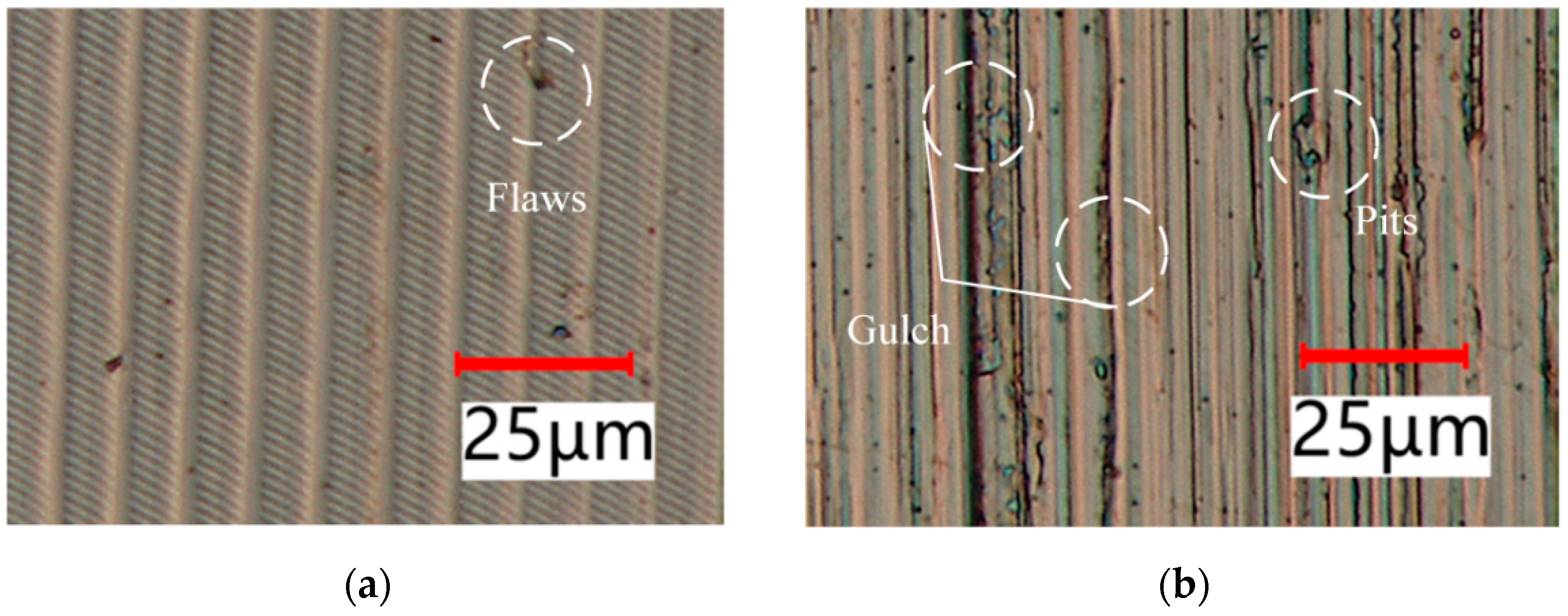
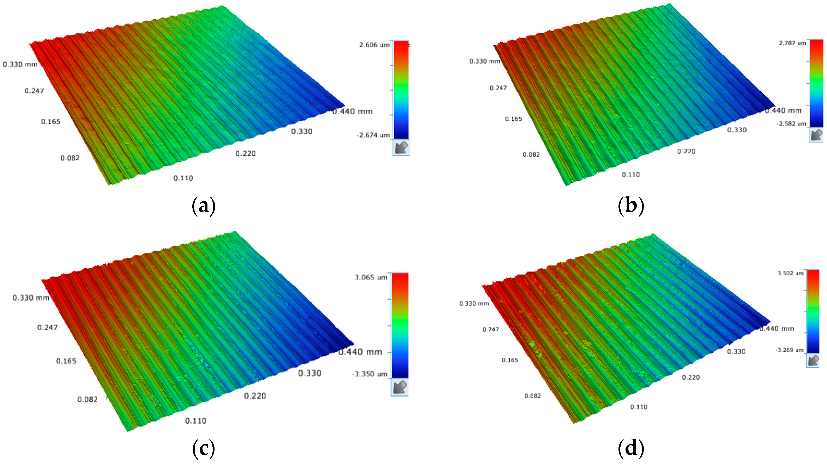
3.1.2. Surface Topography and Surface Roughness

Figure 4 gives the ultrasonic elliptical vibration cutting (UEVC) and conventional cutting (CC) of nickel-based superalloys under the parameters of Table 3 regarding the workpiece surface morphology and surface roughness change rule. The parameters of cutting speed of 4 m/min, feed rate of 17 μm/rev, depth of cut of 3 μm, ultrasonic amplitudes of Ay = 4.5 μm and Az = 1.2 μm, and a tool nose radius of 0.5 mm were selected. The Figure 4 shows the cutting depth and machining surface roughness in bar graph; as the cutting depth (ap) increases, the surface roughness (Ra) also gradually increases. The reason for this phenomenon is that, with the increasing cutting depth, the contact area between the tool and the workpiece increases, and the contact area between the chip and the front face increases, which leads to an increase in the cutting force, which produces a large number of harmful vibrations, which worsens the surface morphology of the workpiece and increases the surface roughness. Comparing the two cutting methods, the increase in surface roughness is more significant for regular cutting than for ultrasonic elliptical vibratory cutting because regular cutting is more sensitive to changes in the depth of the cut. In contrast, ultrasonic elliptical vibratory cutting reduces average cutting forces and, at the same time, reduces tool wear and extends tool life. So, ultrasonic elliptical vibration has less effect on the variation of cutting depth, which is a significant advantage in surface roughness and provides better surface quality.
By observing the surface of the workpiece using super depth of field, we can see the significant difference between ultrasonic elliptical vibratory cutting and regular cutting in Figure 5. As can be observed from Figure 5a, ultrasonic elliptical vibratory cutting formed a series of complex and uniform vibration traces on the surface of the workpiece, and these textures showed apparent regularity. Specifically, the unique interrupted cutting of ultrasonic elliptical vibratory cutting processes create a delicate texture, causing the machined surface to display a unique texture pattern. In contrast, the surface of conventional cutting is rougher, with irregular veins that leave visible pits and scratches from the cutting process. These irregular veins and pear grooves significantly reduce the overall aesthetics and functionality of the workpiece, as shown in Figure 5b. These undesirable phenomena have improved substantially after the adoption of ultrasonic elliptical vibratory cutting technology. This advanced machining technology reduces surface defects and effectively enhances overall quality of the machined surface, thus providing crucial technical support for high-precision machining.
Using white-light interferograms to observe the surface morphology, it can be seen from Figure 6a that there is a significant difference between ultrasonic elliptical vibratory cutting and ordinary cutting. The surface after ultrasonic elliptical vibratory cutting shows a high degree of flatness, with the vibration traces on the surface being uniform and regular and the contrast between the peaks and valleys of the waveforms being prominent. These features indicate the remarkable effect of the ultrasonic elliptical vibration technique in improving the surface quality. On the other hand, from Figure 6b, we can observe that the surface of regular cutting has cut marks of different sizes with many burrs and pits on the surface, thus seriously affecting the roughness and overall appearance of the surface.
Overall, ultrasonic elliptical vibratory cutting (UEVC) technology offers significant advantages in terms of surface quality improvement, especially when dealing with high hardness and difficult-to-machine materials, and it is more effective in reducing surface defects and improving the overall quality of fabrication than conventional continuous cutting methods. This makes UEVC an attractive technology option for precision manufacturing and high-performance materials processing.

3.2. Analysis of the Effect of Cutting Parameters on Surface Roughness

3.2.1. Effect of Cutting Speed on Surface Roughness

A bar graph of the variation of machined surface roughness of the workpiece with cutting speed for the parameters of Table 4 is given in Figure 7. The parameters of feed rate of 16 μm/rev, depth of cut of 3 μm, ultrasonic amplitude of Ay = 4.5 μm and Az = 1.2 μm, and a tool nose radius of 0.5 mm were selected. Surface roughness tends to decrease and then increase with increasing cutting speed. Specifically, the roughness of the machined surface shows a continuous decreasing trend when the cutting speed is increased from 1 m/min to 3 m/min, indicating that the cutting effect is gradually optimized in this speed range. However, when the cutting speed is increased to 4 m/min, the roughness of the machined surface increases sharply, and deterioration occurs. Therefore, selecting the appropriate cutting speed during ultrasonic elliptical vibratory cutting of GH4169 is crucial. Maintaining the cutting speed below 3 m/min can effectively control the surface roughness at a low level, thus obtaining an ideal machined surface.
Figure 8 shows the white-light interferograms for cutting speeds of 1 m/min, 2 m/min, 3 m/min, and 4 m/min. From the figure, it can be seen that with the change of cutting speed, the machined surface quality appears to be different, especially when the cutting speed is 4 m/min: The height difference along the feed direction changes very significantly, and the surface quality decreases significantly at this speed. The surface roughness value of ultrasonic elliptical vibratory cutting is more significant when the cutting speed is lower (e.g., 1 m/min and 2 m/min), mainly because at lower cutting speeds, the tool is in contact with the machined surface for a more extended period, which leads to an increase in frictional heat, which promotes the formation of the built-up edge and burrs and may reduce the rigidity of the machine tool due to the frequent action of the tool on the machined surface, thus increasing the roughness of the workpiece surface. On the contrary, when the cutting speed is increased to 4 m/min, although the contact time between the tool and the machined surface is reduced, at the same time, the cutting force increases, and the cutting temperature rises [23], which is also detrimental to the improvement of surface quality. Especially in high-speed cutting conditions, the contact time between the chip and the front face of the tool is shortened, which may lead to unstable cutting force and accelerated tool wear, affecting the machined surface quality. Therefore, choosing a reasonable cutting speed ensures excellent surface morphology and low surface roughness. Machining quality and productivity can be significantly improved by adjusting the cutting speed.

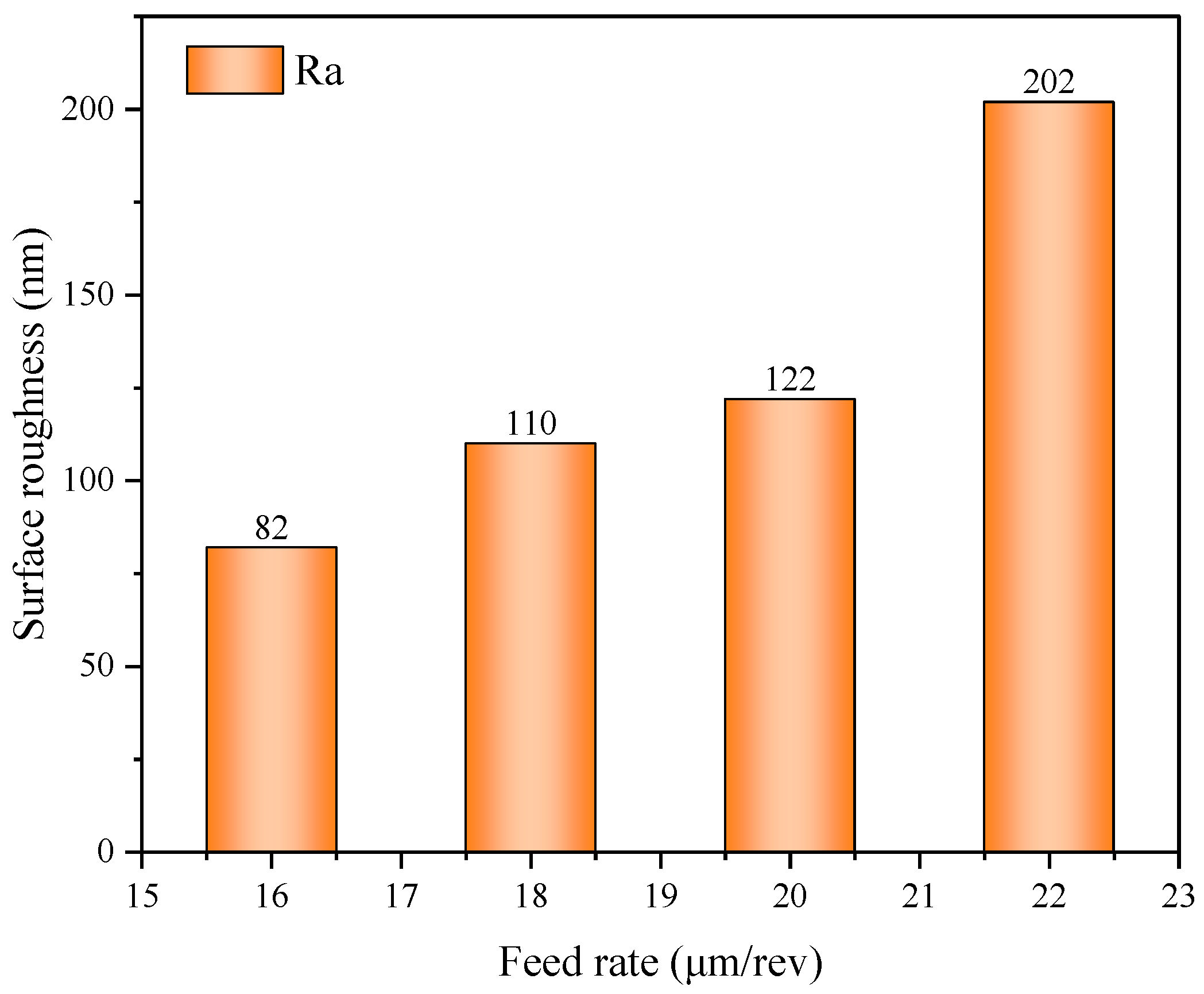
3.2.2. Effect of Feed Rate on Surface Roughness

Figure 9 shows the bar graphs of the variation of surface roughness with feed rate for the parameters of Table 4. The parameters of cutting speed of 1 m/min, depth of cut of 3.5 μm, ultrasonic amplitude of Ay = 4.5 μm and Az = 1.2 μm, and a tool nose radius of 0.5 mm were selected. The surface roughness of the workpiece shows a significant increase with the increase in feed. Specifically, the surface roughness value is 82 nm when the feed rate is 16 μm/rev. When the feed rate is increased to 22 μm/rev, the surface roughness rises sharply to 200 nm, indicating that the feed rate severely affects the surface roughness. The analysis shows that when the feed is small, the machining environment and low thermal conductivity of workpiece may lead to the degradation of the machined surface quality due to the long cutting time; moreover, too large a feed leads to an increase in the residual height of the tool in the feed direction, which directly affects the workpiece surface roughness.
As shown in Figure 10 below, we set the feed rate to 16 μm/rev, 18 μm/rev, 20 μm/rev, and 22 μm/rev to study its effect on the surface roughness of the workpiece. The results clearly show that at a feed rate of 16 μm/rev, the material-removal rate per unit time is low, which results in relatively low cutting forces and temperatures, and under these conditions, due to the gentler cutting action, the ultrasonic elliptical vibration produces a more detailed “fish scale”-shaped vibration pattern, which contributes to a smoother surface. However, with the progressive increase in feed, we observed an increasing residual height on the workpiece surface, which directly led to a significant increase in surface roughness. Specifically, higher feeds increase the cutting forces, making the cutting area rougher and deteriorating the surface quality.
In the ultrasonic elliptical vibratory cutting process, the correct feed selection is critical to ensure the surface quality of the workpiece. When the feed increases, the thickness of the cutting layer and the width of the chips increases as well, leading to a rise in the contact area between the cutting edge of tool and the surface of workpiece. This change increases the friction and cutting force and the difficulty of chip discharge, leading to the buildup of chips between the front face of the tool and the workpiece. This can cause chattering, making the machining process stage unstable and thus reducing the surface quality of the workpiece. In addition, more comprehensive chips are not easy to break during the cutting process and tend to wrap around the tool, which may lead not only to scratches on the surface of the workpiece but also exacerbate the wear of the tool, further destroying the quality of the surface of the workpiece. However, ultrasonic elliptical vibratory cutting technology has the advantage of reducing the phenomena of chipping the built-up edge and burrs, which provides strong technical support to improve the quality of cutting machining. Therefore, in the actual cutting process, as far as possible, we recommend choosing a smaller feed, such as f = 16 μm/rev, to balance the machining efficiency and workpiece surface quality.

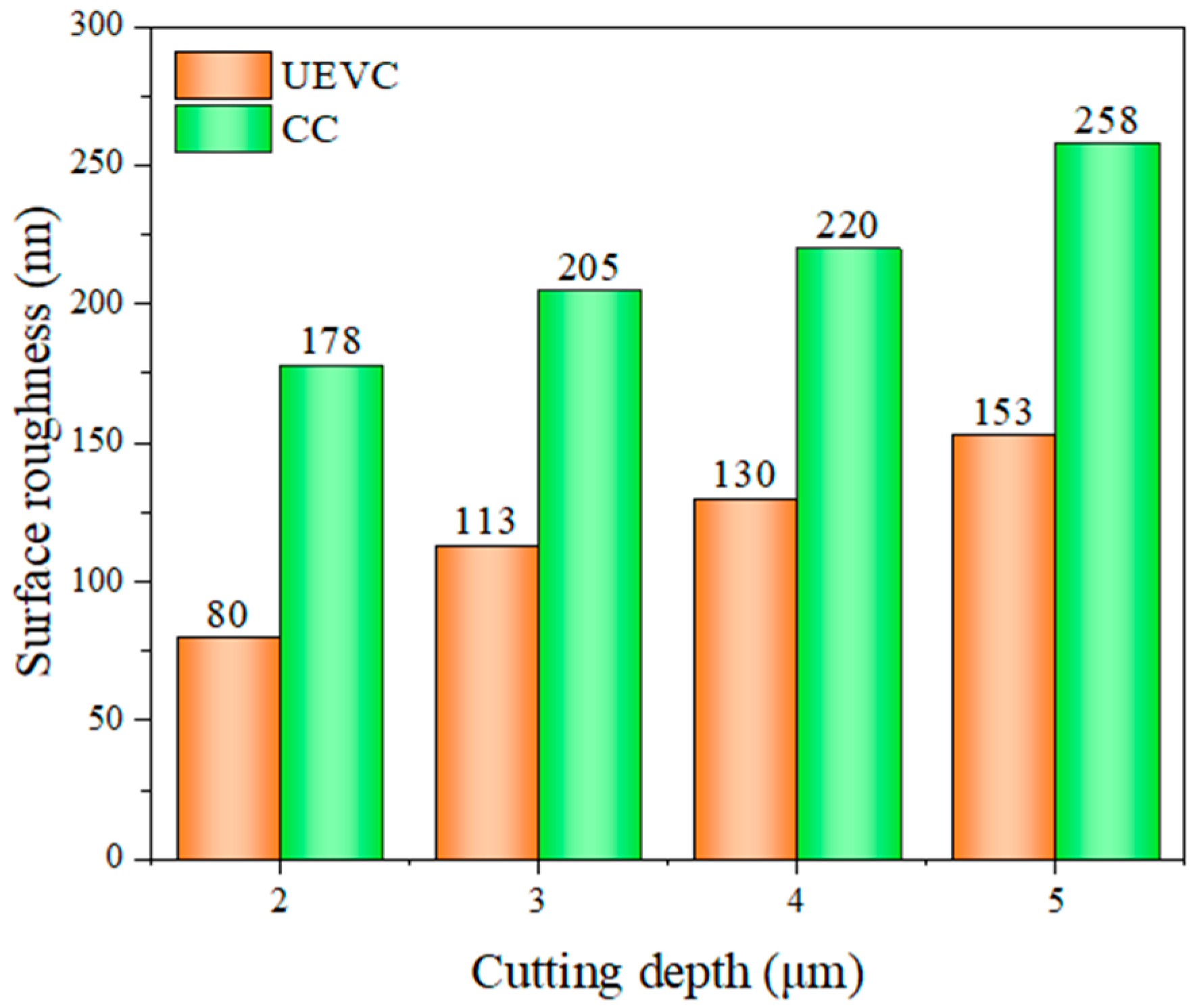
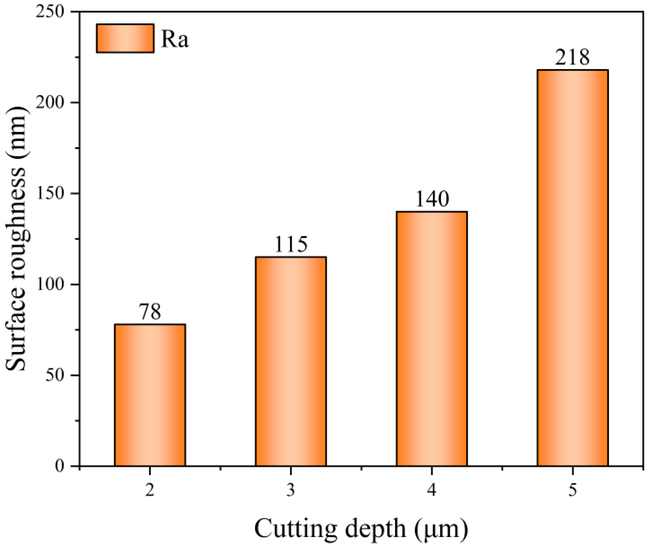
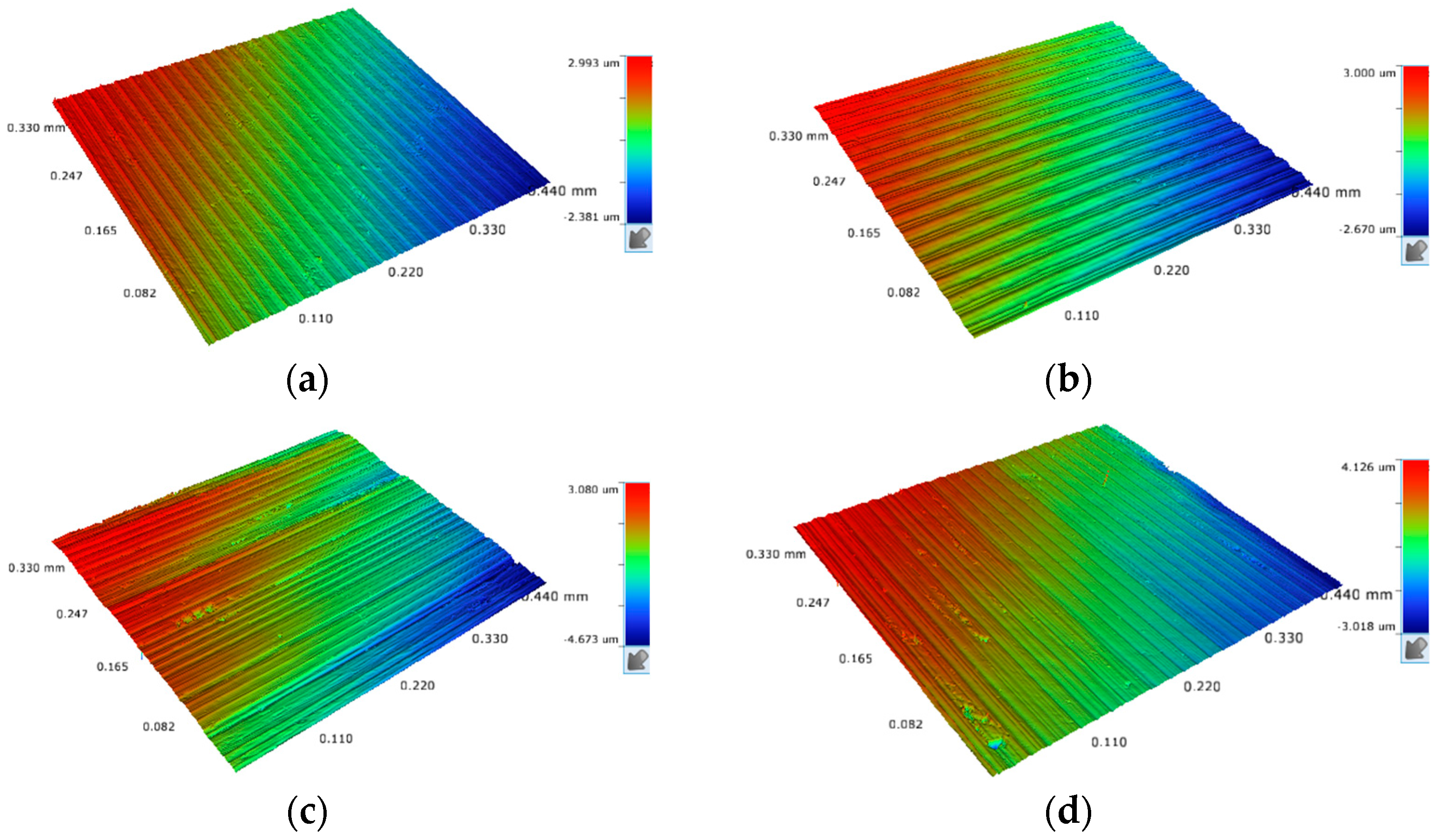
3.2.3. Effect of Cutting Depth on Surface Roughness

The bar graph of the variation of the machined surface roughness of the workpiece with cutting depth under the parameters of Table 4 is given in Figure 11. The parameters of cutting speed of 4 m/min, feed of 18 μm/rev, ultrasonic amplitude of Ay = 4.5 μm and Az = 1.2 μm, and a tool nose radius of 0.5 mm were selected. It can be observed from the provided histogram that the surface roughness of the workpiece increases gradually with the increase in cutting depth. When the cutting depth was increased from 2 μm to 4 μm, the surface roughness increased linearly, However, a significant increase in surface roughness was observed when the cutting depth was increased from 4 μm to 5 μm, indicating that deeper depths of cut had exceeded the benefits provided by the ultrasonic vibrations, resulting in less efficient removal of material during the cutting process, increased cutting forces, and an accumulation of heat of cutting, which significantly deteriorated the surface quality.
To further analyze the influence factors of surface roughness with a cutting depth, Figure 12 shows the surface roughness maps obtained by white-light interferometer at cutting depths of 2 μm, 3 μm, 4 μm, and 5 μm. From the figure, it can be seen that as the cutting depth increases from 2 μm to 5 μm, uneven bumps and burrs are formed on the surface of the workpiece, which increases the surface irregularity and damage, making the quality of the workpiece surface worse and worse. The change in the height of the workpiece is more significant.
During ultrasonic elliptical vibratory cutting, the variation of workpiece surface roughness with cutting depth is related to the magnitude of cutting force. As the cutting depth continues to increase, the area of the diamond tool in contact with the workpiece increases, the actual cutting area increases, and more material needs to be removed, which directly leads to an increase in cutting force. Higher cutting forces can lead to severe deformation of the workpiece surface during the cutting process. They may also cause vibration of the tool and workpiece, making the cutting process unstable and increasing surface roughness. The increased cutting area means greater deformation forces and friction, increasing heat between the tool and the workpiece, affecting the cutting results. Ultrasonic elliptical vibration can effectively reduce the contact time between the tool and the workpiece, thereby reducing heat buildup and friction and helping to improve cutting stability and surface quality. The proper cutting depth allows the cutting forces to be kept within reasonable limits while taking advantage of ultrasonic elliptical vibration to improve machining efficiency and surface finish quality [32].

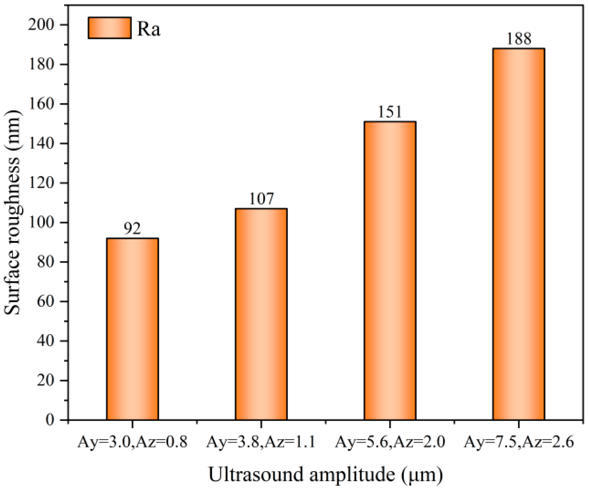
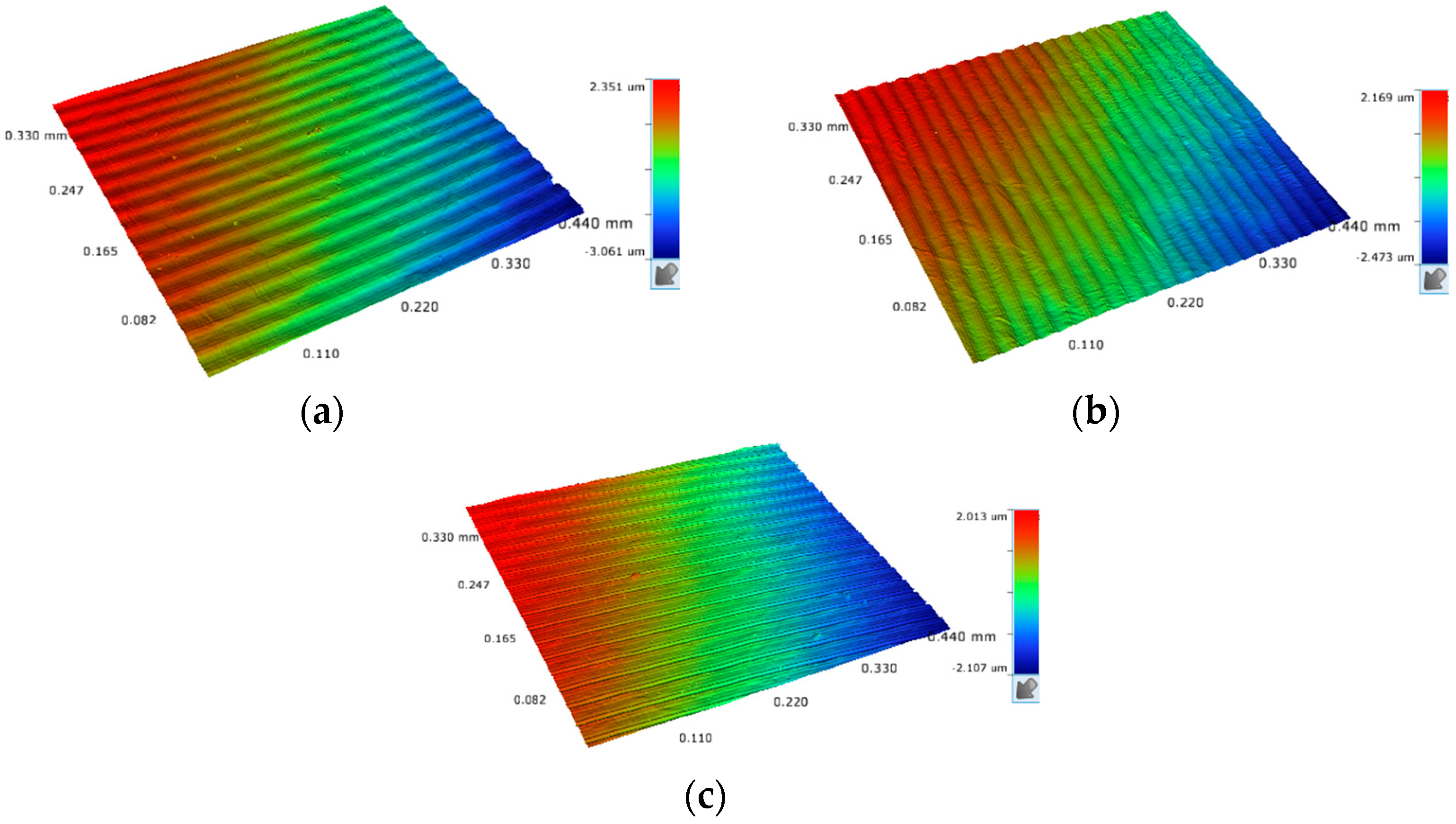
3.2.4. Effect of Ultrasound Amplitude on Surface Roughness

The bar graph of the variation of the machined surface roughness of the workpiece with ultrasonic amplitude (A) for the parameters of Table 4 is given in Figure 13. The parameters of cutting speed of 5 m/min, feed of 24 μm/rev, depth of cut of 2 μm, and a tool nose radius of 0.5 mm were selected. It can be seen from the figure that the value of surface roughness of the workpiece increases with the increase of ultrasonic amplitude in both directions. The surface roughness was minimized when the ultrasonic amplitude was Ay = 3.0 μm and Az = 0.8 μm, and the surface roughness was 92 nm. When the ultrasonic amplitude was increased to Ay = 7.5 μm and Az = 2.6 μm, the surface roughness increased dramatically to 188 nm.
Figure 14 shows the 3D surface roughness for four different ultrasonic amplitude parameters. When the ultrasonic amplitude is Ay = 3.0 μm and Az = 0.8 μm, the surface is smooth and basically free of defects, and when it is increased to Ay = 3.8 μm and Az = 1.1 μm, fine vibrational lines can be seen on the surface, and some pits appear. When increased to Ay = 5.6 μm and Az = 2.0 μm, it is obvious that there are chatter marks, and the height of the residual between the two adjacent elliptical vibration cycles increases so that the surface roughness increases, and the surface quality deteriorates; with the amplitude of Ay = 7.5 μm and Az = 2.6 μm, we can see dense chatter marks, the height of the residual is more obvious, and the surface roughness increases sharply.
Ultrasonic elliptical vibratory cutting is an intermittent cutting method, and changing the ultrasonic amplitude affects the contact time between the tool and the workpiece surface. As the ultrasonic amplitude increases, the surface roughness increases at the same time, and the residual height on the workpiece machining surface between two adjacent ultrasonic elliptical vibratory cuts increases due to the increase in the amplitude in the direction of the depth of cut, resulting in a deterioration of the surface topography. When cutting nickel-based high-temperature alloys, although the ultrasonic amplitude gives a great advantage in improving the surface flatness of the workpiece, a larger ultrasonic amplitude has a greater effect on the surface buildup of the workpiece, which will cause the cutting system to be overloaded; the burr will increase, and the flatness of the surface will deteriorate, which will have a deleterious effect on the tool and the surface.

3.2.5. Effect of Tool Nose Radius on Surface Roughness

The bar graph of the variation of surface roughness of the workpiece machined with the tool nose radius for the parameters of Table 4 is given in Figure 15. The parameters of cutting speed of 2 m/min, feed of 16 μm/rev, depth of cut of 2.5 μm, and ultrasonic amplitude of Ay = 4.5 μm and Az = 1.2 μm were selected. From the figure, it can be seen that the surface roughness decreases significantly with the increase of the tool nose radius. When the tool nose radius is re = 0.8 mm, the machined surface morphology of the workpiece becomes flat, and the surface roughness is only 63 nm. In contrast, when the tool nose radius is re = 0.2 mm, the surface of the workpiece is defective, with a surface roughness of up to 115 nm.
During ultrasonic elliptical vibratory machining, the size of the tool nose radius is a critical parameter that directly affects the residual height in the feed direction, which in turn affects the surface roughness of the workpiece. When other cutting parameters are fixed, and the feed is specific, the tool feed residual height is inversely proportional to the tool nose radius. Figure 16 clearly shows this relationship: The larger the tool nose radius, the smaller the feed residual height, the smoother and flatter the machined surface, and the lower the surface roughness of the workpiece. On the contrary, a smaller tool nose radius will result in a more considerable cutting feed height, making the machined surface uneven and prone to surface defects, thus increasing surface roughness and reducing surface quality. However, care should be taken in choosing the tool nose radius, as the tool nose radius of the cutter is too large, leading to an increase in the contact area between the blade and the workpiece, which not only increases the cutting force but also may cause an increase in the cutting temperature, which may ultimately lead to the phenomenon of chattering.
Therefore, in ultrasonic elliptical vibration machining, the tool nose radius should be reasonably selected according to the specific machining requirements and conditions to achieve the best machining effect and surface quality.

4. Conclusions

In this paper, ultrasonic elliptical vibration ultra-precision cutting tests of nickel-based high-temperature alloys were carried out, and the effects of cutting speed, feed, cutting depth, ultrasonic amplitude, and tool nose radius on the machined surface morphology and surface roughness were thoroughly investigated. The main conclusions of the study are as follows:
  • Surface quality improvement: compared to conventional cutting (CC), the surface roughness of ultrasonic elliptical vibratory cutting was reduced by about 55%, 44%, 40%, and 40%, respectively, for the same parameters, significantly improving the quality of the machined surface;
  • Effect of cutting parameters: The surface roughness of the ultrasonic elliptical vibratory cutting process decreased and then increased with the increase of cutting speed, indicating that there exists an optimal cutting speed that can achieve the lowest surface roughness. The surface roughness similarly increased with increasing feed and cutting depth, suggesting that higher feed and cut are not conducive to obtaining a smooth surface. Surface roughness increased with ultrasonic amplitude: The smaller the ultrasonic amplitude, the smoother its surface. An increase in the tool nose radius helped to reduce the surface roughness, and a larger radius of the tip circle reduced the residual height in the feed direction, thus improving the flatness of the machined surface;
  • In this experiment, determined the optimal cutting parameters: a cutting speed of 3 m/min, a feed rate of 16 μm/rev, a cutting depth of 2 μm, an ultrasonic amplitude of Ay = 3.0 μm and Az = 0.8 μm, and a tool nose radius of 0.8 mm. However, vibration trajectory variation significantly affected the surface quality of the workpiece. The effects of different vibration trajectory settings on surface roughness and topography will be studied in future studies.

Author Contributions

Conceptualization and methodology G.H. and M.Z.; Cutting test and result analysis M.Z.; Design and Control of Elliptical Vibration Cutting Device W.X.; Machining programming and operation S.Z. and Y.L.; Surface morphology testing J.L. All authors have read and agreed to the published version of the manuscript.

Funding

This research was funded by Post-Doctoral Science Foundation of China 2021M692386, Tianjin Science and Technology Project 22JCYBJC01630, and Tianjin Education Commission Project 2021KJ028.

Data Availability Statement

The original contributions presented in the study are included in the article, further inquiries can be directed to the corresponding author.

Conflicts of Interest

The authors declare no conflict of interest.

References

  1. Ezugwu, E.O. Key improvements in the machining of difficult-to-cut aerospace superalloys. Int. J. Mach. Tools Manuf. 2005, 45, 1353–1367. [Google Scholar] [CrossRef]
  2. Ezugwu, E.O.; Wang, Z.M.; Machado, A.R. The machinability of nickel-based alloys: A review. J. Mater. Process. Technol. 1999, 86, 1–16. [Google Scholar] [CrossRef]
  3. Arunachalam, R.; Mannan, M.A. Machinability of nickel-based high temperature alloys. Mach. Sci. Technol. 2000, 4, 127–168. [Google Scholar] [CrossRef]
  4. Li, S.; Xiao, G.; Chen, B.; Zhuo, X.; Xu, J.; Huang, Y. Surface formation modeling and surface integrity research of normal ultrasonic assisted flexible abrasive belt grinding. J. Manuf. Process. 2022, 80, 232–246. [Google Scholar] [CrossRef]
  5. Thakur, D.G.; Ramamoorthy, B.; Vijayaraghavan, L. A study on the parameters in high-speed turning of superalloy Inconel 718. Mater. Manuf. Process. 2009, 24, 497–503. [Google Scholar] [CrossRef]
  6. Chen, J.; Yin, H.; Kang, G.; Sun, Q. Fatigue crack growth in cold-rolled and annealed polycrystalline superelastic NiTi alloys. Acta Mech. Solida Sin. 2018, 31, 599–607. [Google Scholar] [CrossRef]
  7. Zhang, X.; Yang, L.; Wang, Y.; Lin, B.; Dong, Y.; Shi, C. Mechanism study on ultrasonic vibration assisted face grinding of hard and brittle materials. J. Manuf. Process. 2020, 50, 520–527. [Google Scholar] [CrossRef]
  8. Hsu, C.Y.; Lin, Y.Y.; Lee, W.S.; Lo, S.P. Machining characteristics of Inconel 718 using ultrasonic and high temperature-aided cutting. J. Mater. Process. Technol. 2008, 198, 359–365. [Google Scholar] [CrossRef]
  9. Zhang, S.J.; To, S.; Wang, S.J.; Zhu, Z.W. A review of surface roughness generation in ultra-precision machining. Int. J. Mach. Tools Manuf. 2015, 91, 76–95. [Google Scholar] [CrossRef]
  10. Zou, P.; Xu, Y.; He, Y.; Chen, M.; Wu, H. Experimental investigation of ultrasonic vibration assisted turning of 304 austenitic stainless steel. Shock. Vib. 2015, 1, 817598. [Google Scholar] [CrossRef]
  11. Ulutan, D.; Ozel, T. Machining induced surface integrity in titanium and nickel alloys: A review. Int. J. Mach. Tools Manuf. 2011, 51, 250–280. [Google Scholar] [CrossRef]
  12. Klotz, T.; Delbergue, D.; Bocher, P.; Lévesque, M.; Brochu, M. Surface characteristics and fatigue behavior of shot peened Inconel 718. Int. J. Fatigue 2018, 110, 10–21. [Google Scholar] [CrossRef]
  13. Zhou, J.; Bushlya, V.; Avdovic, P.; Ståhl, J.E. Study of surface quality in high speed turning of Inconel 718 with uncoated and coated CBN tools. Int. J. Adv. Manuf. Technol. 2012, 58, 141–151. [Google Scholar] [CrossRef]
  14. Zhou, X.; Zuo, C.; Liu, Q.; Lin, J. Surface generation of freeform surfaces in diamond turning by applying double-frequency elliptical vibration cutting. Int. J. Mach. Tools Manuf. 2016, 104, 45–57. [Google Scholar] [CrossRef]
  15. Kurniawan, R.; Kumaran, S.T.; Ali, S.; Nurcahyaningsih, D.A.; Kiswanto, G.; Ko, T.J. Experimental and analytical study of ultrasonic elliptical vibration cutting on AISI 1045 for sustainable machining of round-shaped microgroove pattern. Int. J. Adv. Manuf. Technol. 2018, 98, 2031–2055. [Google Scholar] [CrossRef]
  16. Tong, J.; Wei, G.; Zhao, L.; Wang, X.; Ma, J. Surface microstructure of titanium alloy thin-walled parts at ultrasonic vibration-assisted milling. Int. J. Adv. Manuf. Technol. 2019, 101, 1007–1021. [Google Scholar] [CrossRef]
  17. Shamoto, E.; Moriwaki, T. Ultaprecision diamond cutting of hardened steel by applying elliptical vibration cutting. CIRP Ann. 1999, 48, 441–444. [Google Scholar] [CrossRef]
  18. Shamoto, E.; Moriwaki, T. Study on elliptical vibration cutting. CIRP Ann. 1994, 43, 35–38. [Google Scholar] [CrossRef]
  19. Moriwaki, T.; Shamoto, E.; Inoue, K. Ultraprecision ductile cutting of glass by applying ultrasonic vibration. CIRP Ann. 1992, 41, 141–144. [Google Scholar] [CrossRef]
  20. Kim, G.D.; Loh, B.G. Direct machining of micro patterns on nickel alloy and mold steel by vibration assisted cutting. Int. J. Precis. Eng. Manuf. 2011, 12, 583–588. [Google Scholar] [CrossRef]
  21. Babitsky, V.; Kalashnikov, A.; Meadows, A.; Wijesundara, A. Ultrasonically assisted turning of aviation materials. J. Mater. Process. Technol. 2003, 132, 157–167. [Google Scholar] [CrossRef]
  22. Lu, D.; Wang, Q.; Wu, Y.; Cao, J.; Guo, H. Fundamental turning characteristics of Inconel 718 by applying ultrasonic elliptical vibration on the base plane. Mater. Manuf. Process. 2015, 30, 1010–1017. [Google Scholar] [CrossRef]
  23. Zao, H. Theoretical and Experimental Investigations on Ultrasonic Elliptical Vibration Cutting of Nickel-based Superalloy. Ph.D. Thesis, Northeastern University, Boston, MA, USA, 2019. [Google Scholar]
  24. Tong, J.; Zhao, J.; Chen, P.; Zhao, B. Effect of ultrasonic elliptical vibration turning on the microscopic morphology of aluminum alloy surface. Int. J. Adv. Manuf. Technol. 2020, 106, 1397–1407. [Google Scholar] [CrossRef]
  25. Wu, Y.; Wang, Q.; Li, S.; Lu, D. Ultrasonic assisted machining of nickel-based superalloy Inconel 718. Superalloys Ind. Appl. 2018, 15, 708. [Google Scholar]
  26. Feng, L. Research on the Process Mechanism of Difficult-To-Machine Materials with Vibration Assisted Diamond Cutting. Master’s Thesis, Huazhong University of Science and Technology, Wuhan, China, 2021. [Google Scholar]
  27. Pan, Y.; Kang, R.; Dong, Z.; Du, W.; Yin, S.; Bao, Y. On-line prediction of ultrasonic elliptical vibration cutting surface roughness of tungsten heavy alloy based on deep learning. J. Intell. Manuf. 2022, 33, 675–685. [Google Scholar] [CrossRef]
  28. Brehl, D.E.; Dow, T.A. Review of vibration-assisted machining. Precis. Eng. 2008, 32, 153–172. [Google Scholar] [CrossRef]
  29. Ma, C.; Shamoto, E.; Moriwaki, T.; Wang, L. Study of machining accuracy in ultrasonic elliptical vibration cutting. Int. J. Mach. Tools Manuf. 2004, 44, 1305–1310. [Google Scholar] [CrossRef]
  30. Jieqiong, L.; Jinguo, H.; Xiaoqin, Z.; Zhaopeng, H.; Mingming, L. Study on predictive model of cutting force and geometry parameters for oblique elliptical vibration cutting. Int. J. Mech. Sci. 2016, 117, 43–52. [Google Scholar] [CrossRef]
  31. Cheng, G. Study on Machining Mechanism and Related Technology of Nickel Base Superalloy GH4169. Ph.D. Thesis, Changchun University of Technology, Changchun, China, 2023. [Google Scholar]
  32. Jing, S. Mechanism and Experimental Study on Ultrasonic Elliptical Vibration Turning of Difficult Machining Materials. Master’s Thesis, Northeastern University, Boston, MA, USA, 2017. [Google Scholar]
Figure 1. The cutting experimental platform: (a) apparatus for UEVC; (b) schematic illustration of the experimental platform.
Applsci 14 05515 g001
Figure 2. Ultrasonic amplitude measuring device.
Applsci 14 05515 g002
Figure 3. Cutting mechanisms and material-removal mechanisms: (a) ultrasonic elliptical vibration cutting process; (b) conventional cutting process.
Applsci 14 05515 g003
Figure 4. Surface roughness change with cutting depth in UEVC and CC.
Applsci 14 05515 g004
Figure 5. Optical image of surface magnified 1000×: (a) surface in UEVC; (b) surface in CC.
Applsci 14 05515 g005
Figure 6. Surface roughness of different cutting methods: (a) UEVC surface roughness; (b) CC surface roughness.
Applsci 14 05515 g006
Figure 7. Surface roughness change with cutting speed in UEVC.
Applsci 14 05515 g007
Figure 8. Surface morphology at different cutting speed: (a) v = 1 m/min; (b) v = 2 m/min; (c) v = 3 m/min; (d) v = 4 m/min.
Applsci 14 05515 g008
Figure 9. Surface roughness change with feed rate in UEVC.
Applsci 14 05515 g009
Figure 10. Surface morphology at different feed rate: (a) f = 16 μm/rev; (b) f = 18 μm/rev; (c) f = 20 μm/rev; (d) f = 22 μm/rev.
Applsci 14 05515 g010
Figure 11. Surface roughness change with cutting depth in UEVC.
Applsci 14 05515 g011
Figure 12. Surface morphology at different cutting depth: (a) ap = 2 μm; (b) ap = 3 μm; (c) ap = 4 μm; (d) ap = 5 μm.
Applsci 14 05515 g012
Figure 13. Surface roughness change with ultrasonic amplitude in UEVC.
Applsci 14 05515 g013
Figure 14. Surface morphology at different ultrasonic amplitudes: (a) Ay = 3.0 μm, Az = 0.8 μm; (b) Ay = 3.8 μm, Az = 1.1 μm; (c) Ay = 5.6 μm, Az = 2.0 μm; (d) Ay = 7.5 μm, Az = 2.6 μm.
Applsci 14 05515 g014
Figure 15. Surface roughness change with tool nose radius in UEVC.
Applsci 14 05515 g015
Figure 16. Surface morphology at different tool nose radii: (a) re = 0.2 mm; (b) re = 0.5 mm; (c) re = 0.8 mm.
Applsci 14 05515 g016
Table 1. Main performance parameters of GH4169.
WorkpieceDensity
ρ (kg/m3)
Hardness
(HB)
Yield Strength
σ0.2 (MPa)
Tensile Strength
σb (MPa)
Elongation
δs (%)
Shrinking Percentage
ψ (%)
GH41698280240126014302440
Table 2. Main chemical components of GH4169.
ElementNiCrNbMoTiAlCSiMnFe
Wt (%)51.75175.152.931.070.450.0420.210.0321.36
Table 3. Experimental parameters of UEVC and CC.
No.Cutting Speed
v/(m/min)
Feed Rate
f/(μm/rev)
Cutting Depth
ap/(μm)
Ultrasonic ConditionTool Nose Radius
re/(mm)
14172ultrasonic and non-ultrasonic0.5
241730.5
341740.5
441750.5
Table 4. Experimental parameters of GH4169 cutting.
No.Cutting Speed
v/(m/min)
Feed Rate
f/(μm/rev)
Cutting Depth
ap/(μm)
Ultrasonic Amplitude
A/(μm)
Tool Nose Radius
re/(mm)
11163Ay = 4.5, Az = 1.20.5
22163Ay = 4.5, Az = 1.20.5
33163Ay = 4.5, Az = 1.20.5
44163Ay = 4.5, Az = 1.20.5
51163.5Ay = 4.5, Az = 1.20.5
61183.5Ay = 4.5, Az = 1.20.5
71203.5Ay = 4.5, Az = 1.20.5
81223.5Ay = 4.5, Az = 1.20.5
94182Ay = 4.5, Az = 1.20.5
104183Ay = 4.5, Az = 1.20.5
114184Ay = 4.5, Az = 1.20.5
124185Ay = 4.5, Az = 1.20.5
135242Ay = 3.0, Az = 0.80.5
145242Ay = 3.8, Az = 1.10.5
155242Ay = 5.6, Az = 2.00.5
165242Ay = 7.5, Az = 2.60.5
172162.5Ay = 4.5, Az = 1.20.2
182162.5Ay = 4.5, Az = 1.20.5
192162.5Ay = 4.5, Az = 1.20.8
Table 5. Ultrasonic amplitude selection.
No.1234
Cutting direction amplitude Ay (μm)3.03.85.67.5
Feed direction amplitude Az (μm)0.81.12.02.6
Disclaimer/Publisher’s Note: The statements, opinions and data contained in all publications are solely those of the individual author(s) and contributor(s) and not of MDPI and/or the editor(s). MDPI and/or the editor(s) disclaim responsibility for any injury to people or property resulting from any ideas, methods, instructions or products referred to in the content.

