Article

Study of the UHPC–NC Interfacial Bonding Properties of Steel Tubes with Internally Welded Reinforcement Rings

1
College of Civil Engineering and Architecture, Guangxi University, Nanning 530004, China
2
Guangxi Key Laboratory of Disaster Prevention and Mitigation and Engineering Safety, Nanning 530004, China
*
Author to whom correspondence should be addressed.
Appl. Sci. 2024, 14(13), 5604; https://doi.org/10.3390/app14135604
Submission received: 1 June 2024 / Revised: 23 June 2024 / Accepted: 26 June 2024 / Published: 27 June 2024

Abstract

:
Ultra-high-performance concrete (UHPC) has the advantages of high strength, excellent durability performance, etc., and its compressive strength is several times that of normal concrete (NC). Due to the role of materials such as steel fibers, the tensile strength of UHPC is higher than that of NC. For steel-tube concrete columns in corrosive seawater environments, UHPC–NC columns with welded ring reinforcement inside the steel tube are proposed to strengthen the interfacial bonding performance, and the effects of seawater corrosion of steel-tube concrete are studied. Eight steel-tube UHPC–NC specimens were designed for push-out tests. The steel tubes were internally constructed with glossy unconstructed and reinforcing rings, with the core concrete with UHPC used below and the C40 plain concrete used above. By examining push-out load, slip displacements, and steel-tube wall strains, this study analyzed the influence of different factors on the bond behavior and failure mechanism of bond-slip in shear-resistant reinforcing ring connectors. The push-out simulation of the steel-tube concrete was carried out using ABAQUS 2021 software, and the simulation results were compared with the experimental results, which showed good agreement. The results show that the bond strength of the steel tube–concrete column interface can be significantly improved by using the construction measures of internally welded reinforcement rings; for specimens with the same percentage of core concrete UHPC and C40 thickness, the bond strength of the two rings was significantly improved by approximately 33% over that of the one-ring reinforcement ring; corrosive environments will degrade the bond strength of the steel tube–concrete column interface.

1. Introduction

Ultra-high-performance concrete (UHPC), a new type of fiber-reinforced cementitious composite material with high strength, excellent durability, and many other advantages, has been promoted for highways, railways, nuclear power, and other projects and has gradually replaced normal concrete (NC) to increase toughness [1,2,3,4]. By infusing UHPC into a steel tube to form concrete filled steel tube (CFST) composite structures, the constraint effect of the outer steel tube can be used to limit the development of brittleness, and both the compressive strength and deformation resistance are improved [5,6].
Previous studies have shown that CFSTs are geometrically discontinuous members, and the transfer of loads between steel tubes and core concrete requires sufficient bond strength to ensure that the steel tubes are structurally well bonded with the core concrete, and that the two are working together when the external forces act only on the steel tubes or the core concrete [7,8,9]. A large number of experimental studies and theoretical analyses have been conducted on the interfacial bond-slip of CFSTs [10,11,12]. Virdi and Dowling [13] first introduced the push-out test method in 1975 to study bonding between steel tube–concrete interfaces in CFSTs; this method can measure the whole process of the slip at the interface between the steel tube and concrete and determine the ultimate bond strength, and it is still the most important method according to Shakir-Khalil [14,15], who conducted push-out tests on 40 concrete-filled hollow-section steel tubes and 56 concrete-filled hollow-section steel tubes and showed that the cross-sectional form of the members, the size of the members, and the type of shear connection setup had a large influence on the bond strength. Tao et al. [16] conducted rolling tests on steel-pipe concrete specimens with different types of interfaces (normal interface, interface with shear bolts, and interface with inner ring). The results showed that welding an inner ring on the inner surface of the steel pipe was the most effective method to improve the bond strength, followed by welding shear bolts and using expanded concrete. Dong et al. [8] studied the bond strengths of steel tubes with studs, circular ribs, vertical ribs, and a combination of the three construction forms within the tube. The test results showed that circular ribs and vertical ribs inside the steel tube can also significantly increase the bond strength. Feng et al. [17] carried out repeated push-out tests on steel-tube concrete specimens and concluded that the interfacial bond strength and interfacial frictional resistance decreased with the increase in the number of repeated push-out test loadings in the same direction, and the interfacial shear capacity generally decreased with the increase in the strength of the core concrete. Alemayehu et al. [18] investigated the bond-slip behavior of 11 steel-tube concrete monolithic columns through push-out tests and finite element analysis. They concluded that steel-tube concrete columns without mechanical connectors inside the steel tubes do not meet the existing code requirements and need to be constructed with additional mechanical connectors. Wang et al. [19] carried out push-out tests on steel-plate concrete and steel-tube concrete, and they concluded that bond strength increases with the increase in the surface roughness of the steel tube and decreases with the increase in the age of the concrete and the long-term loading at the interface, while roughness increases and decreases with the age of the concrete and long-term loading at the interface, respectively. They also noted that the bond strength is not a constant value during the service life of steel-tube concrete members. Chen et al. [20] studied the bond strength of steel-tube concrete and the use of expanded concrete in the Seger Plaza Building and considered problems such as elastic deformation, creep, and concrete shrinkage of steel tubes and core concrete under stress and time, which led to differences in the deformation of the two materials (steel tubes and concrete) due to differences in their properties, which, in turn, led to debonding and affected the service performance of the overall structure. The literature highlights several key contributions. There are many factors affecting the bond strength of CFSTs, and the interfacial bond strength decreases during the service period of the members. When the bond strength is low, the interface even appears to be partially separated, which affects the normal use of the members. Most of the core concretes used in the previous push-out tests have primarily focused on NC, and the bond strength of specimens with UHPC as the core concrete has rarely been investigated. The research on the bond-slip performance of steel-tube UHPC-NC is still in its initial stages. When the bond strength of CFSTs is insufficient, additional measures are needed to improve it. There are fewer studies on the effect of internally welded reinforcement ring construction on bond-slip performance. In this paper, the influence of internal welded reinforced ring structures on bond-slip properties is studied.
For CFSTs in a corrosive seawater environment, an ultra-high-performance concrete steel tube, a C40 ordinary concrete steel tube structure, and a steel tube with an internal welded reinforcement ring structure were Push-out and simulations were conducted to study the bond damage process; analyze the damage mode, bond strength, and load–slip curves; and verify the accuracy of the model. Combined with finite element analysis, the effect of internally welded reinforcement rings on the bonding performance of steel-tube UHPC-NC members was investigated to provide a reference for future related research and engineering applications.

2. Test Method

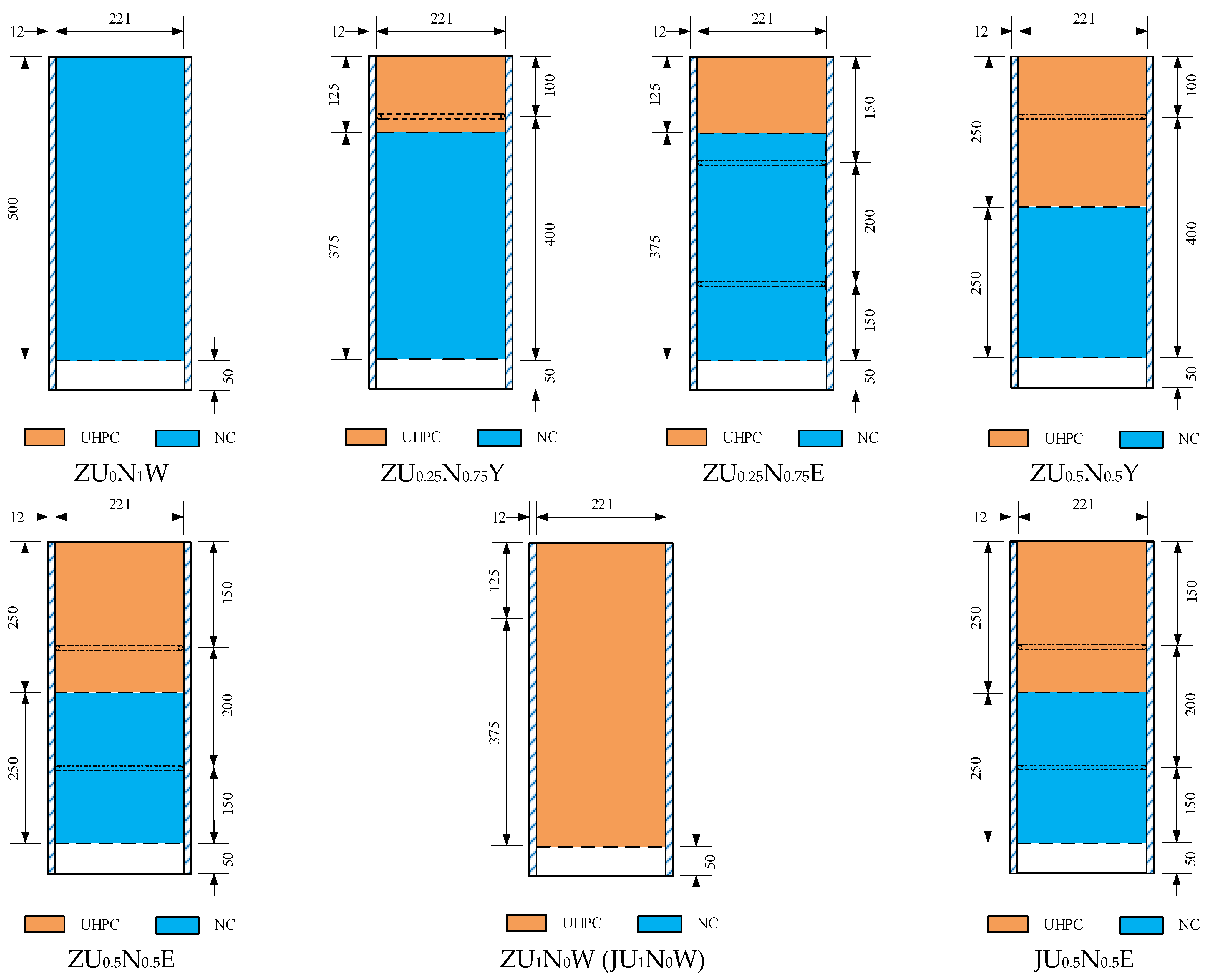
2.1. Specimen Design

In this experiment, eight push-out specimens of steel-tube UHPC–NC short columns were designed to investigate the interfacial bonding properties of CFSTs by using the push-out test, which involves leaving a distance of empty steel tube at the lower end of the round CFSTs without pouring concrete and applying a vertical load on the upper end of the specimens on the core concrete surface. The slip between the steel tube and the core concrete occurs through the vertical loading. The main variation parameters of the specimens included the thickness percentages of the different core concretes (UHPC and NC), the curing conditions (natural condition curing and corrosion curing), and the type of interface configuration (glossy no-ring configuration, one-ring rebar ring configuration, and two-ring rebar ring configuration). The steel tubes were all 245 mm in diameter, 12 mm in thickness, and 550 mm in length; the specimens were 550 mm in length, and the total height of concrete placement (bond length) was 500 mm. The specimen parameters are shown in Table 1. The specimen dimensions, the location of the measures of the steel tubes’ internal welded rebar ring construction, and the location of the core concrete casting are shown in Figure 1. To simulate the effect of seawater environmental media on the interfacial bond performance of steel-tube concrete, the molded concrete specimens were immersed in 5% sodium chloride solution for three months after standard curing, along with the corresponding steel-tube concrete specimens. The remaining concrete specimens and steel-tube concrete specimens were cured under natural conditions.
The UHPC was made of R120 premix developed by Hunan Mingxiang Science and Technology Development Co., Ltd., Hunan, China which consists of cement, core material powder, quartz sand, and steel fiber in certain proportions; the NC was made of C40 ordinary commercial concrete. The detailed mix ratios of UHPC and C40 are shown in Table 2 and Table 3, respectively. The steel used for the steel tubes was of Q355 grade, and the inner welded reinforcement rings were made of HPB300-grade steel rebar. The mechanical properties of the steel material were tested according to the specifications [21]. The measured basic mechanical properties are shown in Table 4, and the basic mechanical properties of the concrete measured according to the Standard for Test Methods of Mechanical Properties of Ordinary Concrete (GB/T 50081-2002) [22] are shown in Table 5.

2.2. Test Process

This test was carried out in the 12,000 kN large-scale multifunctional structural test system of Guangxi University Laboratory. The measurement points and loading schematic diagram of the launching test are shown in Figure 2. This test was mainly based on the Standard for Test Methods for Concrete Structures (GB/T 50152-2012) [23]. First, the empty steel tube reserved for the test specimen was inverted on the steel mat plate below, which is called the concrete measured end; then, a steel mat block slightly smaller than the inner diameter of the steel tube was placed between the upper part of the test specimen and the loading plate to ensure that the axial load completely acted on the concrete, which is called the concrete loaded end. Four displacement gauges were set up: two linear variable differential transformers (LVDTs) were symmetrically deployed at the loaded end, and two rotary variable differential transformers (RVDTs) were symmetrically deployed at the free end. The pull ropes of the RVDTs were vertically and symmetrically bound to the two ends of the wooden bar, the wooden block at the reserved empty steel tube was glued to the bottom surface of the core concrete at one end, and the other end was glued to the wooden bar and hung together to achieve the same displacement change in the wooden bar, the wooden block, and the core concrete simultaneously. The load was transferred to the core concrete area at the top by applying it to the steel mat plate, while the bottom was loaded by the steel tube alone.
Before formal loading, the test machine was preloaded to 30 kN to ensure that the test machine was fully compressed between the loading plate, steel pads, and specimen, with no gaps, and to check the reliability of all of the test rigs. Then, the load was applied at a rate of 0.5 mm/min until the displacement of the loading end reached 40 mm when the loading was stopped.

3. Test Results and Analysis

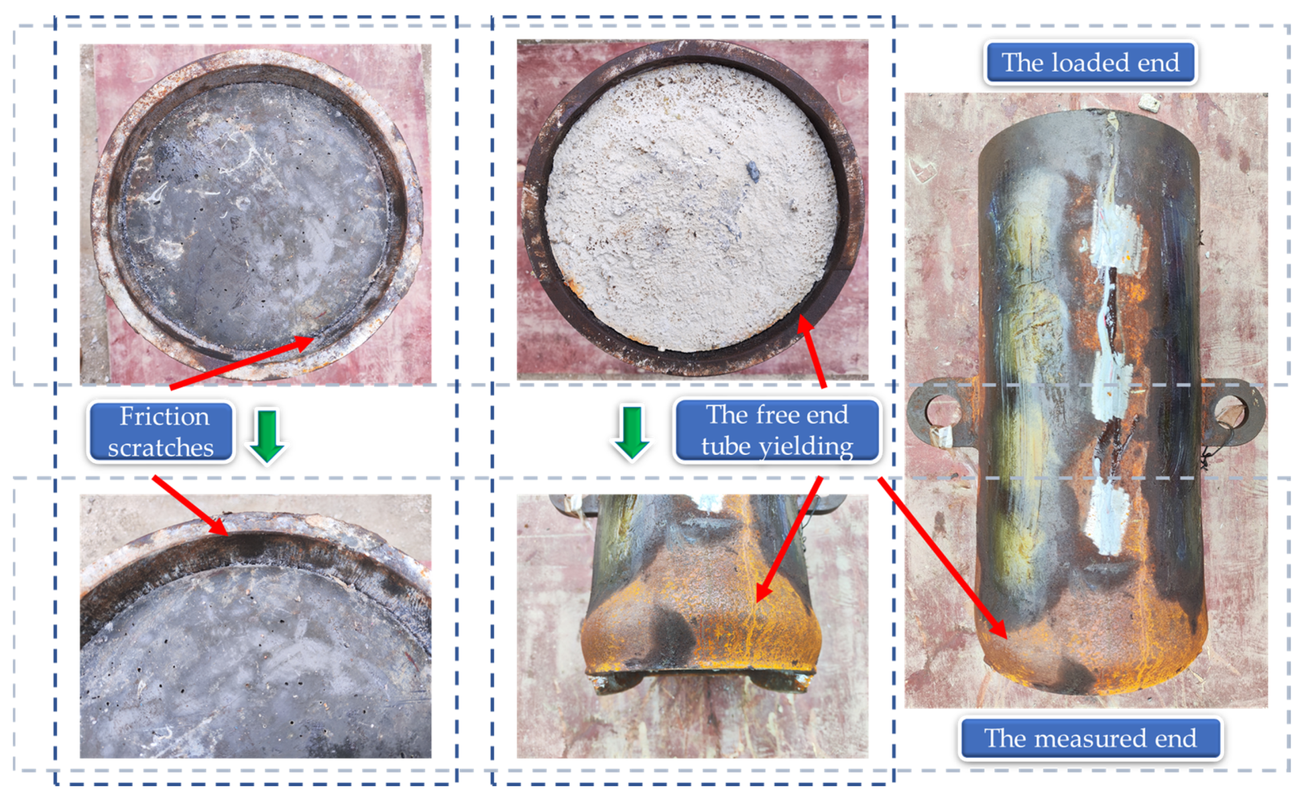
3.1. Test Phenomena and Damage Morphology

In the process of launching the test, all of the specimens emitted a slight ringing sound. The sound of the core concrete’s friction on the steel tube wall was registered when specimen ZU0.5N0.5Y was loaded to 7.50 mm displacement and suddenly thumped loudly. The internal weld reinforcement’s weld fracture sound was registered after the sudden drop in the load rose slowly. The damage process of the test specimen followed a similar law: at the beginning of loading, the steel tube and the core concrete worked together, and relative sliding had not yet occurred between them; with increasing load, the interface cracks developed slowly, and a small misalignment occurred between the steel tube and the core concrete at the loading end when the tension sensor at the measured end produced readings. It can be assumed that, at this time, the interfacial adhesive force failed and, thus, friction and mechanical occlusion played the main roles [24]. After the peak load, the relative sliding of the core concrete continued to occur under the action of the axial load. The test machine load exhibited a stable trend, accompanied by the sound of the concrete being crushed by extrusion, and the internal welded steel rebar ring weld was torn; at this time, friction, mechanical occlusion force, and ring rebar shear joints together transferred the load to the steel tube. The specimen damage morphology after the launch of the test is shown in Figure 3. After removing the steel mat, the loading end of the steel tube–concrete interface was ground, resulting in concrete debris; at the loading end of the inner wall of the steel tube, friction scratches were visible to the naked eye, and the measured end also contained concrete debris. The interface of the smooth unconstructed specimens was relatively flat, with only some slip marks, and the specimens constructed with internally welded reinforcement rings had mostly small concrete fragments. The damage pattern of the specimens depended on their construction type. No local buckling occurred in the tubes of the smooth unconstructed specimens (ZU0N1W, ZU1N0W, and JU1N0W); the specimens with the internally welded one-ring or two-ring reinforcing ring construction all bulged outward at the welded reinforcing rings of the tubes, due to the high thrust of the tubes transmitted from the internally welded reinforcing rings; when the pushout load continued to increase, the stress in the tubes continued to increase beyond the yield stress of the steel. The high thrust in the tubes caused the concrete to squeeze the walls, which explains the bulging deformation of the steel tube walls. From the above analyses, it can be concluded that the existence of internally welded reinforcement rings can largely prevent the rapid development of gaps at the steel tube–concrete interface, transfer axial loads to the steel tube efficiently, and change the damage mode of the interface.

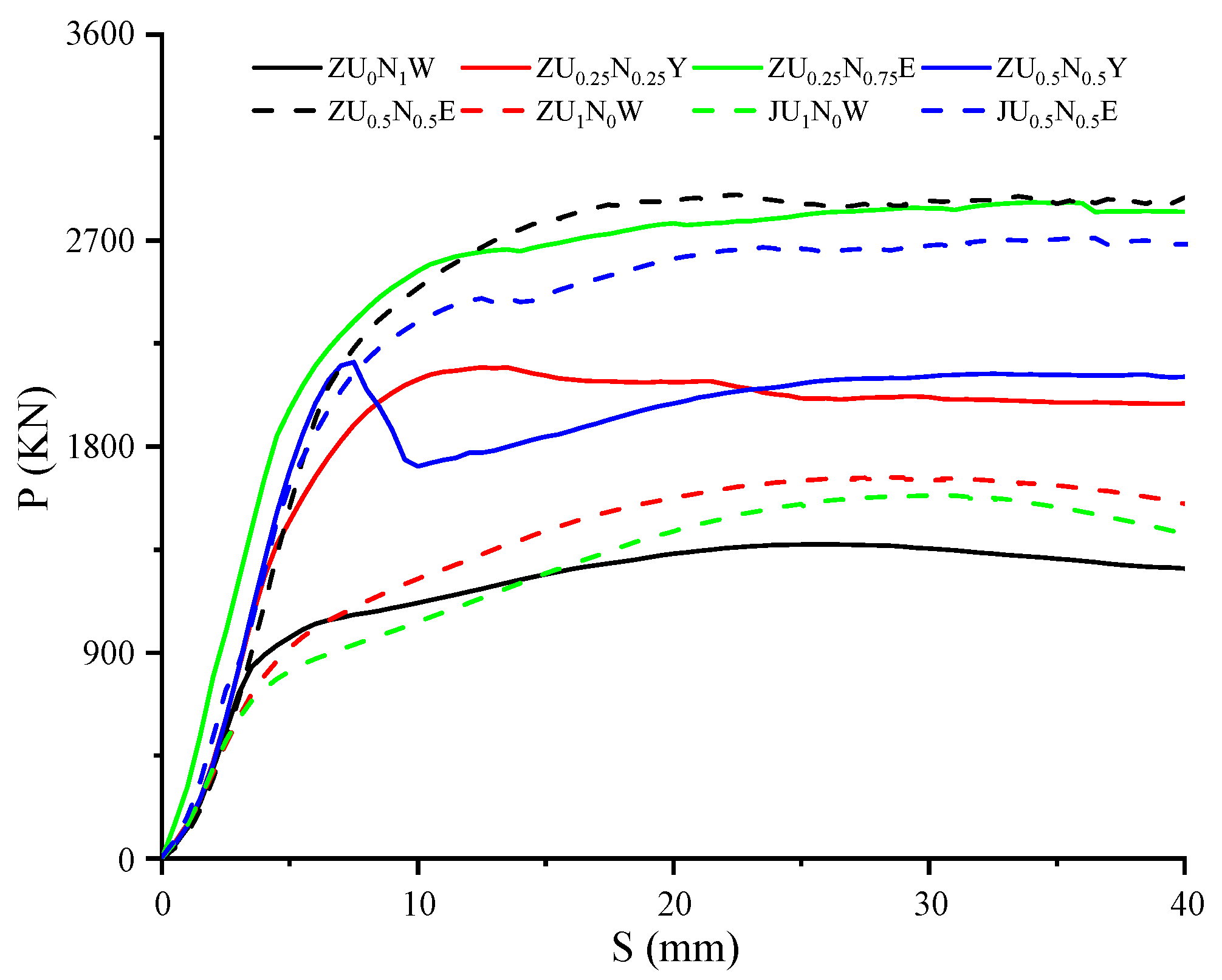
3.2. Bond Load-Slip Curve Analysis

The load-slip (P-S) curves of the eight specimens rolled out of the test specimens are shown in Figure 4. As shown in Figure 4, at the beginning of loading, the slopes of the curves increase, with a linear upward trend, and the curves of the different specimens overlap. With increasing loading, the P-S body is divided into two types: Type 1 has no obvious peak point, and the loading continues to rise, such as the ZU0N1W, ZU1N0W, and JU1N0W specimens, with a rising section, a secondary rising section, and a residual section. Type 2 has no obvious peak point, and the loading tends to reach a stable level in the later stage. There is a rising section and a residual section, and most of the specimens were of this type. Most of the specimens also tended to become stable after the rising section, and the falling section was not obvious, which indicates that the welded steel ring shear connectors improve the steel tube–concrete interfacial bond performance. The residual section of the curve fluctuation proves that, at this time, the welded reinforcement shear connectors still contribute to the interfacial shear capacity.
Similar to ordinary steel-tube concrete, the bond strength τ u at the interface between the steel tube and the core concrete in this test can be calculated according to Equation (1) [25]:
τ u = P u π D 0 l
where P u is the bond-breaking load, D 0 is the inner diameter of the round steel tube, and l is the interface bond length.
From the P-S curves, three characteristic points were identified to analyze the P-S curves directly: the starting point (Ss, Ps), which is the starting point of the rapid development of the slip point; the peak point (Su, Pu), which is the maximum position of the load in the slip process; and the residual point (Sr, Pr), which is the endpoint of the residual section after the peak. The characteristic values of the P-S curve of each specimen, calculated by Equation (1), are shown in Table 6.
Based on the results in Table 6, it can be seen that, for the specimen with core concrete of UHPC, when the inner wall of the steel tube is not set up with any structural measures, the bond strength τ u of ZU1N0W is 4.80 MPa, which is 1.2 times of that of the specimen with core concrete of C40; the reason for this is that the steel fibers of UHPC are mixed into the concrete, and they will be distributed chaotically in the concrete interior. Moreover, they can effectively impede the development of microcracks and formation of macrocracks in the concrete interior, and they promote the development of the friction coefficient of the inner wall of the steel tube. For the specimens with the same percentage of UHPC and C40 thickness in their core concrete, the bond strength of the two-ring rebar ring specimens was significantly improved by about 33% compared with the one-ring rebar ring. The bond strength of all of the specimens constructed with internally welded rebar rings was improved compared with the specimens with glossy no-ring construction measures. In addition, glossy no-ring construction can increase the bond strength by increasing the strength of the concrete, but when the shear joints were welded on the inner wall of the steel tube, the bond strength was not improved significantly with the increase in the proportion of UHPC. Meanwhile, the load was mainly transferred through the shear joints; the bond strength of the two specimens under the corrosive curing was 5% lower compared with that of the specimen under natural curing. In the existing codes, the bond strength of steel-tube concrete is usually taken as a low fixed value. The Chinese code (DBJ/T 13-54-2010) [26] and the European code [27] take the design value of the bond strength of round steel-tube concrete to be 0.23 MPa and 0.55 MPa, respectively. The British code [28] and the Australian code [29] suggest that the bond strength of round steel-tube concrete be taken to be 0.4 MPa, and the U.S. [30] code suggests that the value of the bond strength of round steel-tube concrete be taken to be min (5300 t/D2,1.4 N/mm2). From the bond strength of the speci-mens in Table 6. It can be seen that the bond strength of all specimens is much larger than the reference value of the existing specification, which meets the needs of the project. Compared with the calculated values of the bond strength formulae in the existing literature, all of the specimen test values were greater than the calculated values. This shows that the construction measures of internally welded reinforcement rings are conducive to increasing the bond strength of the members, as shown in Table 7.
As can be seen from the analysis of Figure 5, the longitudinal strain of the specimen’s steel tube was negative, indicating that the steel tube was in a pressurized state during the push-out test. At the beginning of loading, the load is small, and the longitudinal strain of the steel tube changes along the length direction in a non-obvious manner. With increasing load, the different positions of the steel tube’s wall strain exhibited large differences, and the strain at the measured end was much greater than that at the loading end. The load is transferred to the steel tube through the action of bond stress: the faster the change in the strain value, the faster the interface force is transferred here; the greater the bond stress, the closer the specimen is to the measured end; and the faster the change in the strain value, the greater the interface bond stress at the measured end. The longitudinal strain value of the steel tube increases with increasing load, and the strain value at each measurement point also increases more uniformly. The overall distribution of the longitudinal strain value of the steel tube shows a triangular shape, with a larger peak at the bottom and a smaller peak at the top, which indicates that the bond effect on the steel tube is uniformly distributed from the loading end to the measured end, and that the synergistic effect between each reinforcement ring is very good.

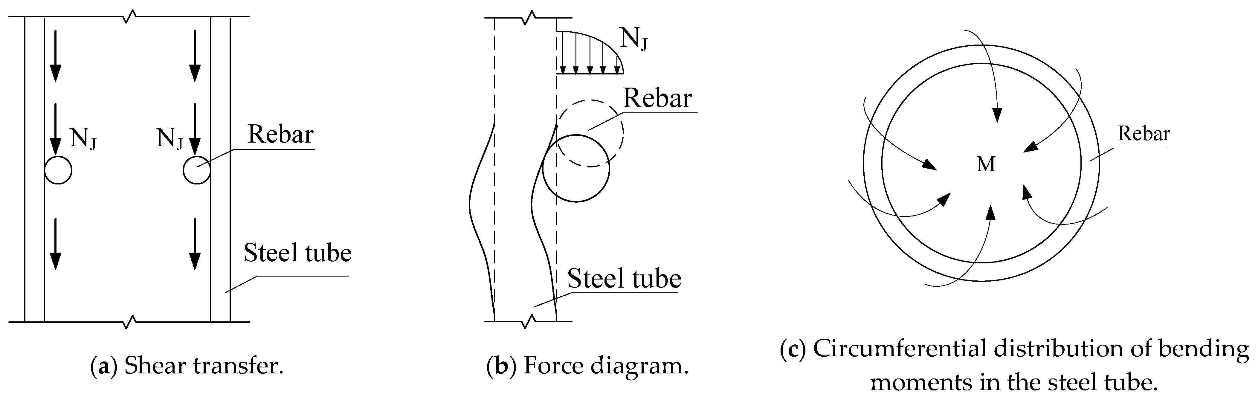
3.3. Failure Mechanism Analysis

The test results show that, for the unconstructed specimen, four main roles are considered: chemical bonding force, mechanical occlusion force, friction force, and precompression stress. In the early stage of loading, these factors share interfacial shear. As the interfacial shear increases, slight longitudinal compression of the core concrete occurs, causing the steel tube–concrete interface at the loading end to undergo displacement misalignment and extend toward the measured end, gradually increasing the chemical bonding force. When the tensile wire sensor at the measured end produces a value, the interface misalignment is transferred to the measured end, which also indicates the disappearance of the chemical bonding force. In addition, the core concrete expands laterally under the launching load, producing an extrusion force on the inner wall of the steel tube, increasing the friction force, and slightly increasing the mechanical occlusion force. The steel tube–concrete interface has an uneven abrasive concrete layer, which also leads to the friction coefficient changing constantly, so the friction force increases, and when the friction force is greater than the loss of the bonding force and the mechanical occlusion force, the P-S curve will show a secondary upward section. There will also be a secondary rising section. For specimens constructed with internally welded reinforcement rings, three main roles are considered: (1) The restraining effect of the reinforcement ring. The reinforcement ring is welded to the inner wall of the steel tube, and because its stiffness in the plane is greater than that of the core concrete, it directly restrains the concrete in the deformation of the steel tube and the concrete under the launching load. This effect converts the resulting squeezing force into mechanical occlusal and frictional forces. (2) The welds play a great role in hindering the slip of the concrete, and even if weld damage occurs, the remaining welds can continue to work until the welds are entirely torn. (3) Regarding the effect of the internal welded reinforcement ring’s anti-shear connectors, as the interface chemical bonding force disappears, the welded reinforcement ring on the inner wall of the steel tube will gradually play a role. At the beginning of the application of force, the steel ring in the elastic phase will gradually resist the increasing shear force with increasing concrete deformation, and its force will be similar to that of the cantilever structure under a uniform load. With increasing load, the welded part of the steel ring and the inner wall of the steel tube will gradually increase the load NJ, and the welded steel parts of the force condition will shift from the original uniform load state into a non-uniform load state. Consequently, the distribution of the force will be transferred to the welded part of the steel ring. Moreover, due to the lower bending stiffness of the outer steel tube surface, shear connectors in the pressure area will assume the formation of the ring distribution of the steel tube wall. The bending moment M will lead to a local bulge deformation at the weld of the steel tube and the connector; the shear connector will therefore produce a flexible rotation, reducing its horizontal projected area, i.e., the pressure-bearing area, and the compressive stress will no longer be balanced, as shown in Figure 6. The extrusion force generated by the lateral expansion of the core concrete will increase the friction at the interface, which is very favorable for the mechanical occlusion force and the shear resistance of the shear connectors. An increase in these resisting forces can cause the load borne by the steel tube–concrete interface to continue increasing. This mutually reinforcing mechanism is highly beneficial to the shear resistance of the interface. Therefore, at this stage, the launching load will be transferred to the steady stage after a substantial growth state until the steel tube yields, the reinforcement weld breaks, or the concrete breaks locally.
For specimens under corrosion maintenance, it has been shown [33] that steel tube–concrete interfacial corrosion is an electrochemical process: α-FeOOH and Fe3O4 produced by Fe in a corrosive seawater environment are exfoliated, and their crystal structure becomes loose and easily falls off; this effect, in turn, makes the interfacial structure loose, thus forming a loose isolation layer, which alters the contact area between the steel tube and the core concrete and influences the bond at the interface. The contact area between the steel tube and the core concrete changes, affecting the bonding force at the interface and leading to a decrease in the bonding capacity.

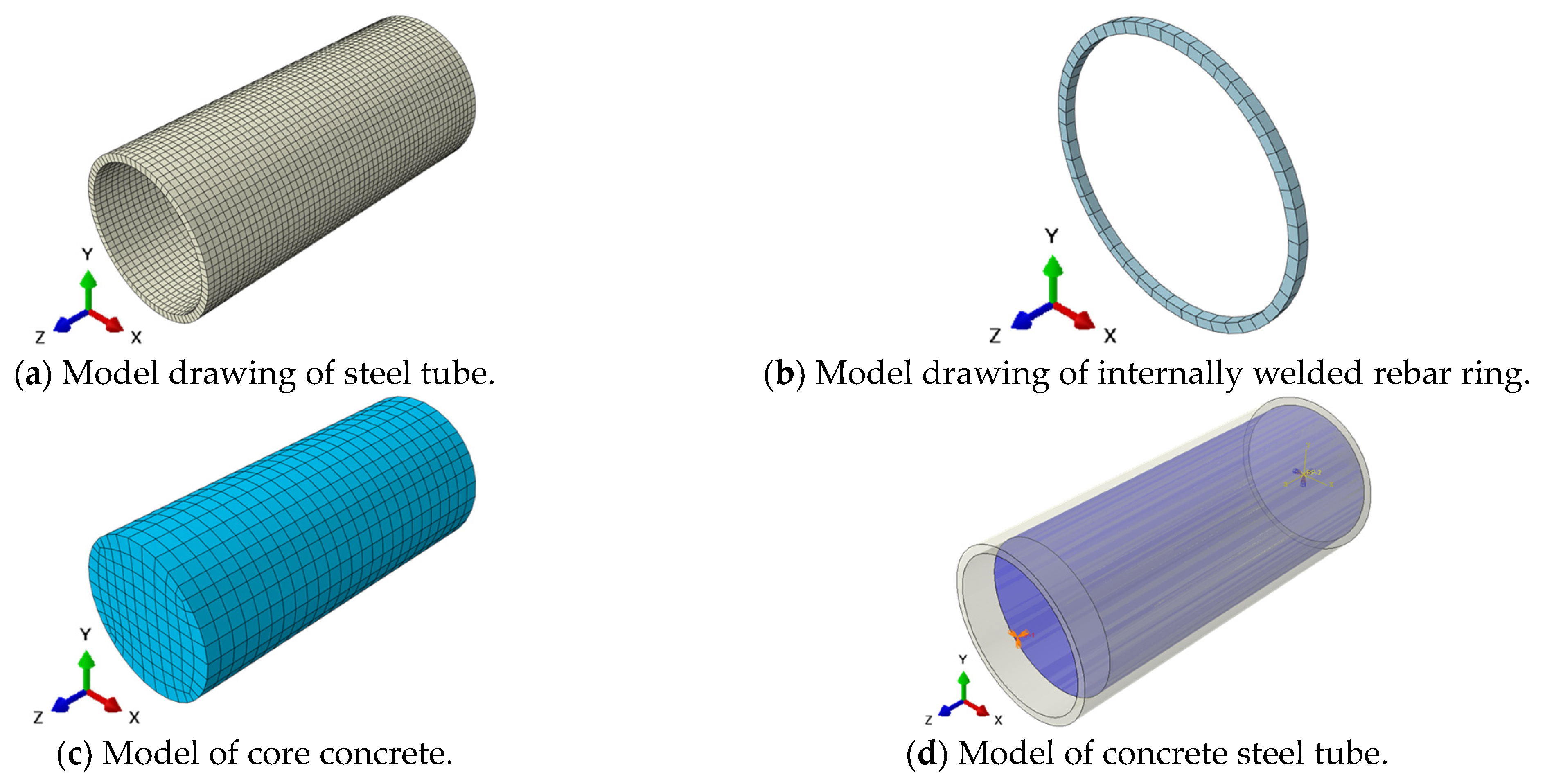
4. Finite Element Analysis

4.1. Subsection

In steel-tube concrete, the constitutive model of core concrete has not yet formed a universally applicable constitutive model of concrete; the most representative constitutive models at home and abroad include those of Linhai Han [34], Shandong Zhong [35], Mander [36], and similar models. In more than one study, when scholars analyzed the mechanical properties of steel-tube concrete by using ABAQUS 2021 software, they often adopted the constitutive model of concrete proposed by Han Linhai, and the finite element simulation results were compared with the test results, the two damage forms, load–displacement curves, and the ultimate bearing capacity of the basic match.
The modulus of elasticity of concrete refers to the provisions of ACI318 [37]. It is calculated as follows:
E c = 4730 ( f c ) 0.5
where f c is the compressive strength of the cylinder (N/mm2), and Poisson’s ratio is taken as 0.2.
The compressive stress–strain curve of the core concrete, concerning the relation described by Linhai Han, which takes into account the restraining effect of the external steel tube on the core concrete, is obtained by using the restraining effect coefficient, expressed as follows:
y = { 2 x x 2 x 1 x β 0 ( x 1 ) 2 + x x > 1
where x = ε / ε c 0 , y = σ / σ c 0 , σ c 0 = f c , ε is the strain of the concrete, ε c 0 is the peak strain of the concrete, ε c c is the cracking strain of the concrete, σ is the stress of the concrete, σ c 0 is the peak stress of the concrete, ε c 0 = ε c c + 800 ξ 0.2 10 6 , ε c c = ( 1300 + 12.5 f c ) 10 6 , and β 0 = ( 2.36 × 10 5 ) [ 0.25 + ( ξ 0.5 ) 7 ] ( f c ) 0.5 0.5 0.12 .
The constraint effect coefficient ξ is expressed as follows:
ξ = A S f y / A c f c u
where f y is the yield strength of the steel tube, A s is the area of the steel tube, f c u is the axial compressive strength of the core concrete, and A c is the area of the core concrete.
The steel principal structure uses the mathematical expression of the model described in the literature [38] for Q235, Q345, Q390, and other low-carbon soft steels and steels commonly used in construction projects. The stress–strain relationship curve is as follows:
σ s = { E s ε s A ε s 2 + B ε s + C f y f y [ 1 + 0.6 ε s ε e 2 ε e 3 ε e 2 ] 1.6 f y ε s ε ε e < ε s ε e 1 ε e 1 < ε s ε e 2 ε e 2 < ε s ε e 3 ε s > ε e 3
where ε e = 0.8 f y / E s , ε e 1 = 1.5 ε e , ε e 2 = 10 ε e 1 , ε e 3 = 100 ε e 2 , A = 0.2 f y / ( ε e 1 ε e 2 ) 2 , B = 2 A ε e 1 , and C = 0.8 f y + A ε e 2 B ε e .

4.2. Boundary Conditions and Cell Meshing

The loading modes of the specimens are all displacement loading, and all degrees of freedom at the free end are constrained. Because of displacement loading, only the Z-direction degrees of freedom are released at the loading end, while all of the degrees of freedom in other directions are constrained. Mesh density is very important for finite element analysis; if the mesh is too rough, it may cause larger errors; if the mesh is too detailed, it will greatly increase the calculation time, resulting in a waste of computer resources. This paper repeatedly adjusted based on many trial calculations; the selection of the appropriate accuracy and computational efficiency of the distribution of the seed and mesh division scheme is shown in Figure 7.

4.3. Interface Contact Modeling

According to the experimental analysis, the damage on the contact surface happens in three stages, i.e., linear elastic behavior, initial damage behavior, and damage development behavior, which correspond to the elastic stage, damage initiation criterion, and damage evolution, respectively, in the ABAQUS cohesive behavior model. Therefore, the cohesive behavior model was used to simulate the bonding of the interface between the steel tube and the concrete, as well as the process of damage evolution. ABAQUS software provides two cohesive force models, namely, the cohesive element model, and the surface-based cohesive behavior model. When the surface-based cohesive behavior model is set up with cohesive contact and friction contact at the same time, the friction contact remains in a dormant state before the surface-based cohesive behavior is destroyed, and the friction contact will be triggered only after it is destroyed, which is consistent with the actual experiments, so the surface-based cohesive behavior model was used to simulate steel tube–concrete interface contact behavior.
Since the actual damage condition of the interface between the steel tube and concrete in this study was of the slip-open type, and there was no tension or tearing, the maximum stress criterion was used for judgment, as shown in Equation (6). When the value of the following equation reaches 1, the criterion will be effective, and then the contact point will be ready to enter the damage evolution stage.
M a x { σ n σ n o , σ s σ s o , σ t σ t o }
Based on the process analysis introduced in Section 3.2, it can be seen that the bond-slip process of steel tube–concrete columns is divided into a rising section and a residual section. Based on the shapes and eigenvalues of the experimental P-S curves, the “two-stage” approach was adopted to address the constitutive relationship of the round steel tube–concrete interface with different structural measures for internal welding [39,40].
τ = { G s S ( S S s ) τ s ( S > S s )
where G s is the bond stiffness, G s = τ s / S s .
Surface-based cohesive behavior models were used for the interactions between the core concrete and the steel tube, and between the rebar ring and the steel tube, while hard contact was used for the interactions between the rebar ring and the concrete, and between the two types of core concrete.

4.4. Discussion of Simulations and Tests

Figure 8 and Figure 9 show the equivalent stress cloud diagrams of the steel tube and core concrete of each specimen, respectively, when the loading displacement is 3 mm, where the upper part is the loaded end and the lower part is the free end. From Figure 8, it can be seen that the stress distribution of the steel tube is greater than that of the upper part of all of the specimens. The surface stress of the steel tube gradually develops to the upper part with increasing load, which is consistent with the results obtained from the actual test, i.e., the transfer of force between the steel tube and concrete is carried out through the bond at the interface, and the force on the steel tube accumulates along the extension of the interface of the steel tube and concrete from the upper part to the lower part of the steel tube. The bottom part of the steel tube is subjected to the greatest force. For the internal welded steel ring specimen, the stress at the steel tube’s internal welded rebar is greater. For the specimens with two welded rebar rings, the stress at the bottom welded rebar ring is greater than that at the upper welded rebar ring. These findings are consistent with those regarding the specimen with the welded steel tube steel rebar ring at the outward bulge and the free end in terms of yielding. Due to the increase in the contact area between the rebar ring’s shear connectors and the core concrete, the load can be efficiently transferred to the steel tube through the shear connectors, so the stress of the steel tube increases with the increase in the number of internally welded reinforcement rings, and the distribution is gradually uniform. Consequently, the bond strength of the specimen is enhanced. For the simulation of corrosion-conditioned specimens, due to the degradation of the interfacial bonds by seawater corrosion, the stress on the steel tube is lower than that of specimens with the same structure.
Figure 9 shows that the upper stress distribution of the concrete of the optical test specimen is greater than the lower stress distribution, which is also consistent with the test results. The transfer of force between the concrete and the steel tube is carried out through the interfacial bond between them, and the lower part of the concrete is subjected to the action of the upper part of the concrete after the latter begins to transfer the strong force from the top to the bottom. Thus, the stress distribution of the lower part of the concrete becomes increasingly smaller. The core concrete of all of the specimens with internally welded rebar ring measures showed obvious compressive stress at the upper surface of the rebar ring, even exceeding the ultimate bearing capacity and crushing phenomenon of the concrete, which is consistent with the phenomenon observed after the specimens were cut.
A comparison of the P-S curves obtained from the steel tube–concrete push-out tests and the computational results of the corresponding models is presented in Figure 10 and Table 8.
Figure 10 and Table 8 show that the errors between the finite element modeling (FEM) results of the ABAQUS-simulated steel tube–concrete specimens and the experimental values (EX) are all within 10%. Both the smooth surface without construction and the internal welded rebar ring construction at the peak load point before the match are very good; the specimen simulation calculation results and the test results of the match are slightly poorer, possibly because of inhomogeneous specimen filling, cracking of the rebar ring weld, concrete contact surface breakage, and other impacts caused by the modeling that cannot account for the impact of these factors. Thus, the simulation of the calculation results will be slightly poorer.
In conclusion, the two-stage cohesion model simplified according to the test in this paper shows good accuracy in the simulation of steel tube–concrete specimens constructed with internal welded rebar reinforcement rings, but due to the scarcity of related studies, the relevant parameters of the cohesion model cannot be determined, and additional experiments and numerical simulations with extended parameters must be carried out to facilitate in-depth validation of the cohesion model’s applicability.

5. Conclusions

In this paper, the bond strength of steel tubes and concrete was experimentally investigated, and the following conclusions were drawn:
(1)
The bond load–slip curve of circular steel-tube concrete with a bare surface and no structure consists of a rising section, secondary rising section, and residual section; the bond load–slip curve of circular steel-tube concrete with an internal welded steel rebar ring structure has a rising section and residual section. The rising section of the load–slip curves of all of the specimens shows a linear relationship.
(2)
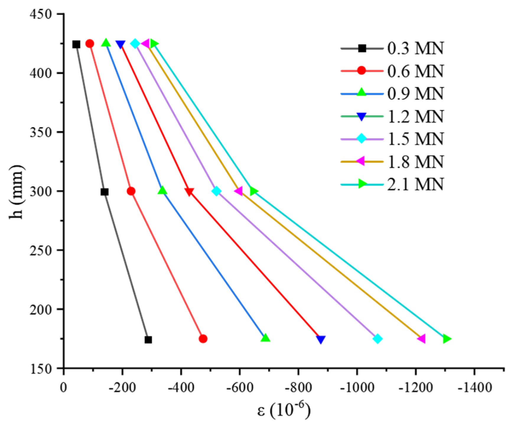
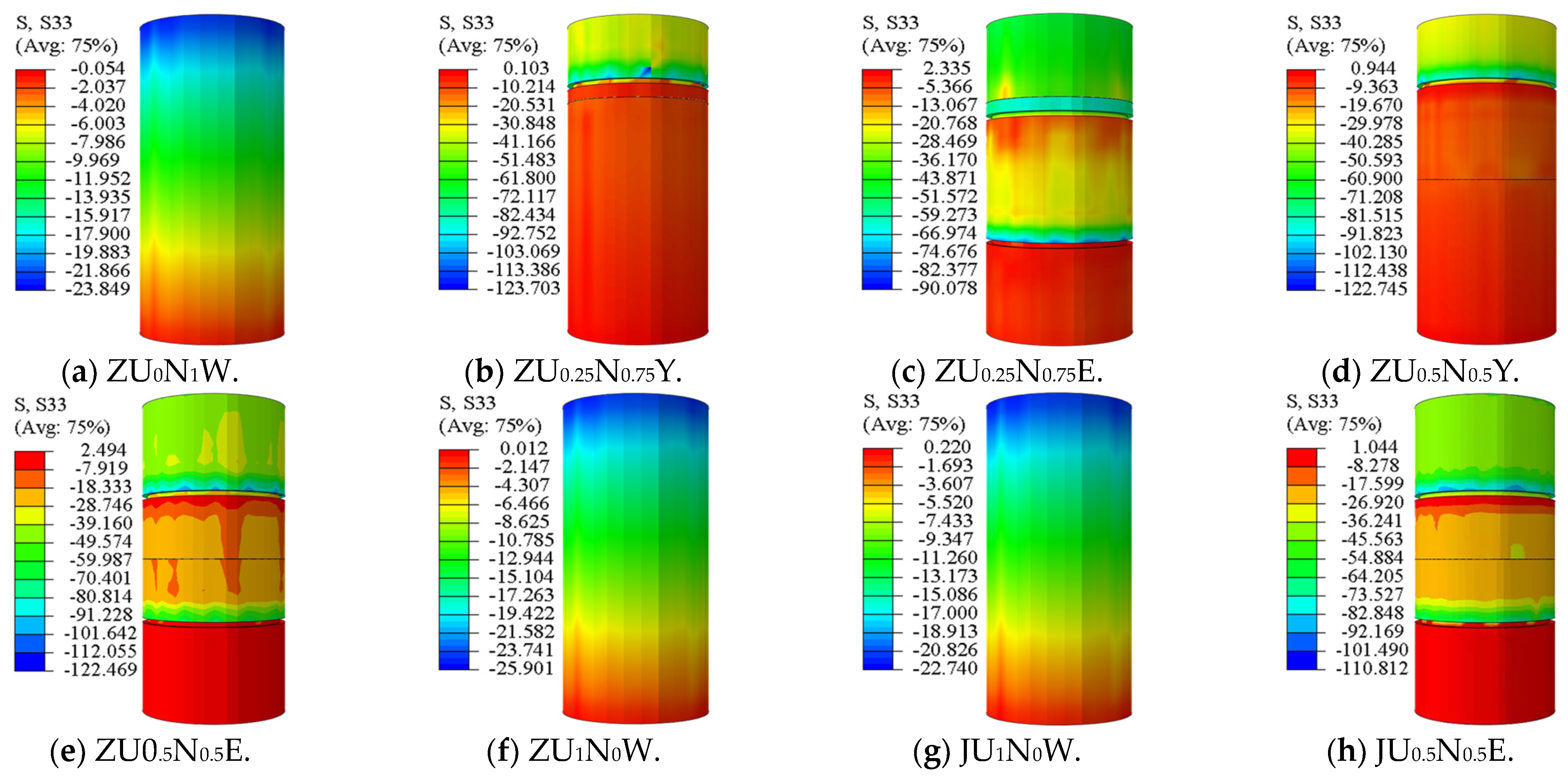
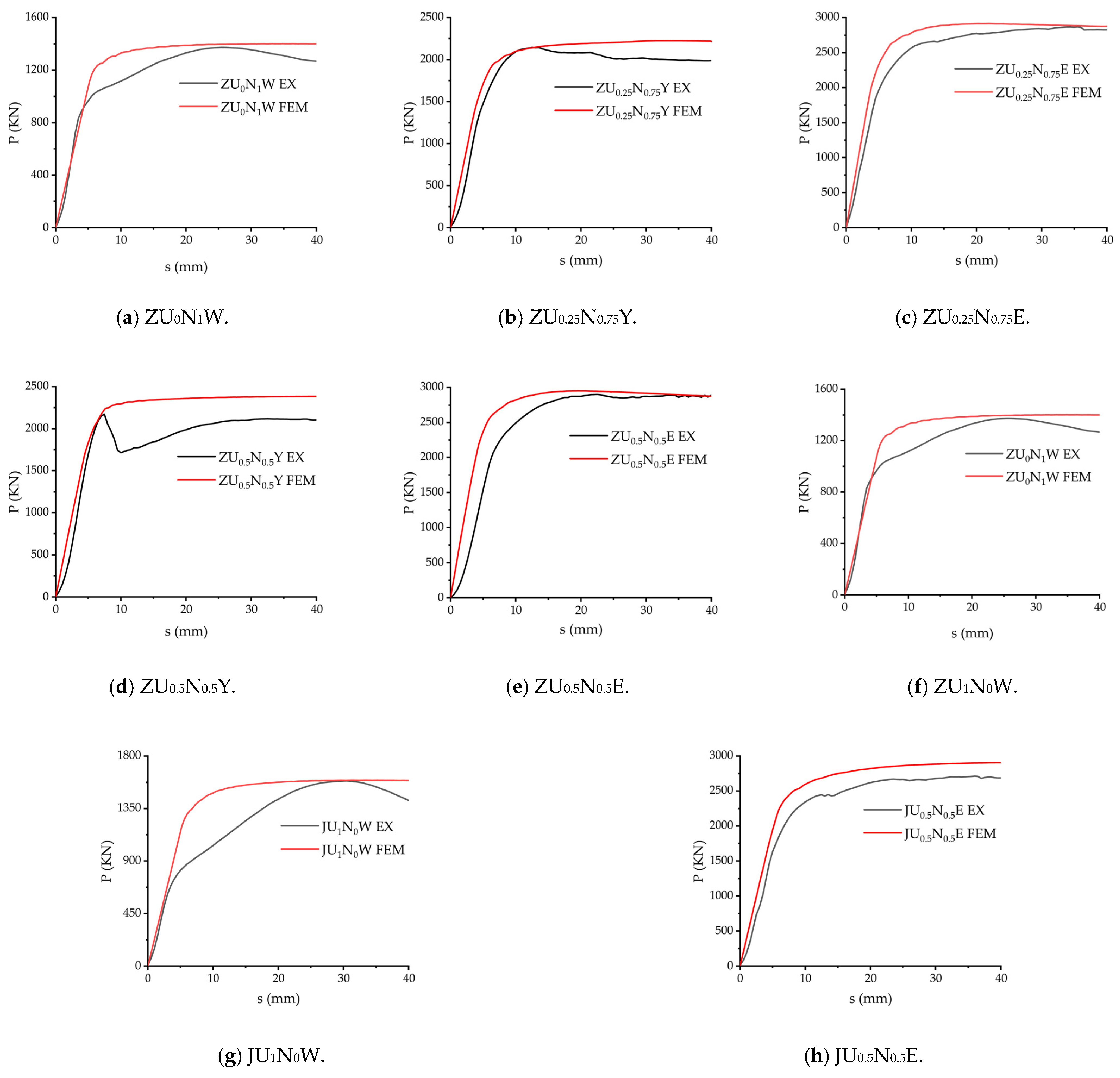
The finite element model of the internally welded steel rebar–steel tube–concrete specimens was established. The calculation results were consistent with the damage patterns, load–displacement curves, and peak load Pu of the tests, which verified the accuracy of the model. The analysis of the stress distribution of the steel-tube concrete showed that the internally welded steel rebar ring construction of the steel tubes could effectively improve the bond strength of the steel tube–concrete interface.
(3)
The bond strength of smooth steel-tube UHPC concrete is 1.2 times greater than that of smooth steel-tube C40 concrete. The bond strength of the core concrete of the internally welded steel ring–steel tube–concrete specimens, along with the bond strength of the two-ring and one-ring rebar configurations, was significantly improved. The construction method, quantity distribution, and welding process of the shear-resistant steel connectors have a large impact on the bond strength of the round steel tube–concrete columns.
(4)
UHPC-NC columns with welded reinforcement rings inside steel tubes have reduced interfacial bond strength in corrosive seawater environments.

Author Contributions

Conceptualization, N.D.; methodology, Z.C.; software, G.L.; validation, W.L.; formal analysis G.L.; investigation, G.L. and W.L.; resources, N.D.; data curation, Z.C.; writing—original draft, G.L.; writing—review and editing, G.L. and Z.C.; funding acquisition, N.D. All authors have read and agreed to the published version of the manuscript.

Funding

This research was funded by the National Natural Science Foundation of China (Grant no. 52268048) and the Guangxi Science and Technology Major Project of China (Gui Ke AA22068066).

Institutional Review Board Statement

Not applicable.

Informed Consent Statement

Not applicable.

Data Availability Statement

The data that support this research can be obtained from the corresponding author upon reasonable request.

Conflicts of Interest

The authors declare that they have no known competing financial interests or personal relationships that could have appeared to influence the work reported in this paper.

References

  1. Shahin, N.; Salah, A.; Kalliontzis, D. Softened membrane model for shear of ultra-high-performance concrete (SMM-UHPC). Eng. Struct. 2024, 308, 117956. [Google Scholar] [CrossRef]
  2. Wang, X.Q.; Chow, C.L.; Lau, D. Multiscale perspectives for advancing sustainability in fiber reinforced ultra-high performance concrete. NPJ Mater. Sustain. 2024, 2, 13. [Google Scholar] [CrossRef]
  3. Zhang, J.J.; Raza, A.; Fu, W.C.; Yuan, C.F. Research on uniaxial compression performance and constitutive relationship of RBP-UHPC after high temperature. Sci. Eng. Compos. Mater. 2024, 31, 20240011. [Google Scholar] [CrossRef]
  4. Ren, L.; Hu, S.J.; Fang, B.W.; Wang, K.; Wen, S. Seismic behavior of UHPC-NC composite columns reinforced by high-strength steel bars. China Earthq. Eng. J. 2022, 44, 285–291, 305. (In Chinese) [Google Scholar] [CrossRef]
  5. Cao, X.; Xie, X.-D.; Zhang, T.-Y.; Du, G.-F. Bond-slip behavior between high-strength steel tube and Ultra-high Performance Concrete. Structures 2023, 47, 1498–1510. [Google Scholar] [CrossRef]
  6. Wang, Q.; Shi, Q.; Lui, E.M.; Xu, Z. Axial compressive behavior of reactive powder concrete-filled circular steel tube stub columns. J. Constr. Steel Res. 2019, 153, 42–54. [Google Scholar] [CrossRef]
  7. Soltanalipour, M.; Ferrer Ballester, M.; Marimon Carvajal, F.; Albareda Valls, A.; Casafont Ribera, M.; Iglesias Toquero, G. New shear transfer system for concrete-filled steel tube (CFST) columns. Steel Constr. 2022, 15, 59–68. [Google Scholar] [CrossRef]
  8. Dong, H.; Chen, X.; Cao, W.; Zhao, Y. Bond-slip behavior of large high-strength concrete-filled circular steel tubes with different constructions. J. Constr. Steel Res. 2020, 167, 105951. [Google Scholar] [CrossRef]
  9. Zhou, P.H.; Xu, L.H.; Gu, Y.S.; Wu, M.; Xu, M.Y.; Huang, L. Experimental study on bond behavior of self-stressing and self-compacting high strength concrete filled steel tube. Eng. J. Wuhan Univ. 2018, 9, 782–789. [Google Scholar] [CrossRef]
  10. Li, H.; Liu, Y.; Zhang, N. Non-linear distributions of bond-slip behavior in concrete-filled steel tubes by the acoustic emission technique. Structures 2020, 28, 2311–2320. [Google Scholar] [CrossRef]
  11. Yu, F.; Chen, T.; Niu, K.; Wang, S.; Fang, Y. Study on Bond-Slip Behaviors of Self-Stressing Steel Slag Concrete-Filled Steel Tube. KSCE J. Civ. Eng. 2020, 24, 3309–3319. [Google Scholar] [CrossRef]
  12. Chen, L.; Dai, J.; Jin, Q.; Chen, L.; Liu, X. Refining bond–slip constitutive relationship between checkered steel tube and concrete. Constr. Build. Mater. 2015, 79, 153–164. [Google Scholar] [CrossRef]
  13. Virdi, K.S.; Dowling, P.J. Bond strength in concrete filled steel tubes. IABSE Proc. 1980, 4, 125–139. [Google Scholar]
  14. Shakir-Khalil, H. Push out strength of concrete-filled steel hollow sections. J. Struct. Eng. 1993, 71, 234–241. [Google Scholar]
  15. Shakir-Khalil, H. Resistance of concrete-filled steel tubes to pushout forces. Struct. Eng. 1993, 71, 234–243. [Google Scholar]
  16. Tao, Z.; Song, T.; Uy, B.; Han, L. Bond behavior in concrete-filled steel tubes. J. Constr. Steel Res. 2016, 120, 81–93. [Google Scholar] [CrossRef]
  17. Feng, R.; Chen, Y.; He, K.; Wei, J.; Chen, B.; Zhang, X. Push-out tests of concrete-filled stainless steel SHS tubes. J. Constr. Steel Res. 2018, 145, 58–69. [Google Scholar] [CrossRef]
  18. Alemayehu, R.W.; Bae, J.; Ju, Y.K.; Park, M.J. Bond Behavior of Concrete-Filled Steel Tube Mega Columns with Different Connectors. Materials 2022, 15, 2791. [Google Scholar] [CrossRef] [PubMed]
  19. Wang, F.; Xie, W.; Li, B.; Han, L. Experimental study and design of bond behavior in concrete-filled steel tubes (CFST). Eng. Struct. 2022, 268, 114750. [Google Scholar] [CrossRef]
  20. Chen, Y.; Wang, G.; Hao, X.B.; Yan, G.H. Evaluation of the Mechanism and Influence Parameters of the Core Concrete Debonding in the Concrete-Filled Steel Tube. Steel Constr. 2022, 37, 20–30. (In Chinese) [Google Scholar] [CrossRef]
  21. GB/T228.1–2010; Metallic Materials-Tensile Testing—Part 1: Method of Test at Room Temperature. China Standard Press: Beijing, China, 2010. (In Chinese)
  22. GB/T 50081–2002; Standard for Test Method of Mechanical Properties on Ordinary Concrete. China Standard Press: Beijing, China, 2013. (In Chinese)
  23. GB/T 50152-2012; Standard for Test Methods for Concrete Structures. China Standard Press: Beijing, China, 2012. (In Chinese)
  24. Lyu, W.; Han, L. Investigation on bond strength between recycled aggregate concrete (RAC) and steel tube in RAC-filled steel tubes. J. Constr. Steel Res. 2019, 155, 438–459. [Google Scholar] [CrossRef]
  25. Kang, X.-L.; Chen, Y.-F.; Zhang, L.; Zhao, H.-T. The oretical analysis of bond-slip constitutive ralationship for CFST. Eng. Mech. 2009, 26, 74–78. (In Chinese) [Google Scholar]
  26. DBJ/T 13-54-2010; Technical Specification for Concrete-Filled Steel Tubular Structures. China Planning Press, China Engineering Construction Association: Beijing, China, 2012. (In Chinese)
  27. EN 1994-1-1:2004; Design of Composite Steel and Concrete Structures-Part 1-1: General Rules and Rules for Buildings: EUROCODE 4(EC4). CEN, Commission of European Communities: Brussels, Belgium, 2004.
  28. BS 5400-5:2005; Steel Concrete and Composite Bridges-Part 5: Code of Practice for the Design of Composite Bridges. British Standard Institute: London, UK, 2005.
  29. AS5100.6-2004; Bridge Design Part 6: Steel and Composite Construction. Standards Australia: Sydney, Australia, 2004.
  30. ANSI/AISC 360-16; Specification for Structural Steel Buildings. American Institute of Steel Construction: Chicago, IL, USA, 2016.
  31. Roeder, C.W.; Cameron, B.; Brown, C.B. Composite Action in Concrete Filled Tubes. J. Struct. Eng. 1999, 125, 477–484. [Google Scholar] [CrossRef]
  32. Wang, Q.-W.; Liu, L.; Shi, Q.-X.; Wang, P. A calculation method of the interface bond strength of reactive powder concrete filled in steel tubes. Eng. Mech. 2020, 37, 41–50. (In Chinese) [Google Scholar] [CrossRef]
  33. Xu, K.C.; Chen, M.C.; He, X.P. Experimental analysis of cfst interface bonding property by corrosion of chlorine ion. Ind. Constr. 2013, 43, 71–74, 98. (In Chinese) [Google Scholar]
  34. Han, L.-H.; Yao, G.-H.; Tao, Z. Performance of concrete-filled thin-walled steel tubes under pure torsion. Thin Wall. Struct. 2007, 45, 24–36. [Google Scholar] [CrossRef]
  35. Zhong, S.T. Structures of Concrete Filled Steel, 3rd ed.; Tsinghua University Press: Beijing, China, 2003. (In Chinese) [Google Scholar]
  36. Mander, J.A.B.; Priestley, M.J.N. Theoretical Stress-Strain Model for Confined Concrete. J. Struct. Eng. 1988, 114, 1804–1826. [Google Scholar] [CrossRef]
  37. ACI 318M02/318RM02; Metric Building Code Requirements for Structural Concrete Commentary. ACI Committee: Farmington Hills, MI, USA, 2002.
  38. Han, L.H. Steel Pipe Concrete Structures; Science Press: Beijing, China, 2004. (In Chinese) [Google Scholar]
  39. Qiao, Q.Y.; Zhang, W.W.; Qian, Z.W.; Cao, W.L.; Liu, W.C. Push-out test of square CFST columns with steel plate shear connectors. J. Huazhong Univ. Sci. Technol. (Nat. Sci. Ed.) 2018, 46, 108–115. (In Chinese) [Google Scholar]
  40. Liu, Y.J.; Liu, J.P.; Chi, J.J. Shear bond behaviors at interface of concrete-filled steel tube. J. Guangxi Univ. (Nat. Sci. Ed.) 2010, 35, 17–23. (In Chinese) [Google Scholar] [CrossRef]
Figure 1. Design drawing of test piece construction measures (mm).
Applsci 14 05604 g001
Figure 2. Specimen loading arrangement (unit: mm).
Applsci 14 05604 g002
Figure 3. Specimen damage morphology.
Applsci 14 05604 g003
Figure 4. P-S curves.
Applsci 14 05604 g004
Figure 5. Longitudinal strain curve of the outer wall of the steel tube for the JU0.5N0.5E specimen.
Applsci 14 05604 g005
Figure 6. Sketch of the forces on the connection and the surrounding steel tube.
Applsci 14 05604 g006
Figure 7. Finite element model diagram.
Applsci 14 05604 g007
Figure 8. Steel tube equivalent stress cloud diagram.
Applsci 14 05604 g008
Figure 9. Concrete equivalent stress cloud.
Applsci 14 05604 g009
Figure 10. The P-S curves of specimens’ finite element results versus test results.
Applsci 14 05604 g010
Table 1. Specimen parameters.
Specimen NumberCore ConcreteTube Size
D × t × l (mm)
Interface Bonding Length (mm)Number of Rebar Rings (Rings)Rebar Diameter and Spacing (mm)
ZU0N1WNC245 × 12 × 5505000-
ZU0.25N0.75YUHPC+NC245 × 12 × 5505001φ8@100
ZU0.25N0.75EUHPC+NC245 × 12 × 5505002φ8@200
ZU0.5N0.5YUHPC+NC245 × 12 × 5505001φ8@100
ZU0.5N0.5EUHPC+NC245 × 12 × 5505002φ8@200
ZU1N0WUHPC245 × 12 × 5505000-
JU1N0WUHPC245 × 12 × 5505000-
JU0.5N0.5EUHPC+NC245 × 12 × 5505002φ8@200
Note: D indicates the outer diameter of the steel tube, t indicates the thickness of the steel tube, l indicates the length of the steel tube, and the interface length indicates the length of the steel tube–concrete interface. Table 1’s specimen number naming rules are as follows: “Z” or “J” at the beginning of the specimen number indicates natural conditions or 5% sodium chloride solution, respectively; the second letter “U” and the third letter “N” stand for UHPC and NC, respectively. The numbers “0”, “0.25”, “0.5 “0”, “0.25”, “0.5”, “0.75”, and “1” are multiplied by the interfacial bond length, i.e., the thickness of the corresponding concrete, and the last letters “W”, “Y”, and “E” represent a smooth surface without rebar, a ring of rebar, and two rings of rebar, respectively.
Table 2. UHPC mix ratio (kg/m3).
ClinkerCore Powder AgentQuartz SandSteel FiberWaterCore Material Water Agent
650413106516013527
Table 3. C40 mix ratio (kg/m3).
Clinker
P·O42.5
Composite Mineral AdmixtureMechanized
Sand
Gravel
5~20 mm
WaterAdditive
26621881888719510.5
Table 4. Mechanical properties of the steel specimens.
Tube Thickness/mmConservation Environment f y /MPa f u /MPa E s /MPa
12Natural conditions377.4490.72.1 × 105
12Sodium chloride solution366.7481.32.1 × 105
Note: fy is the yield strength; fu is the tensile strength; Es is the modulus of elasticity.
Table 5. Mechanical property parameters of the concrete.
Concrete TypeStandard Maintenance fcu/MPaNatural Conservation
fcu/MPa
Sodium Chloride Solution fcu/MPa
C4041.043.338.2
UHPC125.3132.5115.1
Note: fcu is the cubic compressive strength of the concrete.
Table 6. Specimen P-S curve eigenvalues.
Specimen NumberPsPuPrSsSuSrτsτuτr
kNkNkNmmmmmmMPaMPaMPa
ZU0N1W835.621373.511267.583.525.540.02.413.963.65
ZU0.25N0.75Y1577.742145.771986.295.512.540.04.546.185.72
ZU0.25N0.75E1963.422857.482825.575.035.540.05.668.238.14
ZU0.5N0.5Y2169.072154.992102.977.07.540.06.256.216.06
ZU0.5N0.5E2059.422900.622887.816.522.540.05.938.368.32
ZU1N0W920.571665.811550.225.028.540.02.654.804.47
JU1N0W686.871586.891420.183.530.540.01.984.574.09
JU0.5N0.5E1859.322713.332687.066.036.040.05.367.827.74
Note: The average bond τ is the ratio of the load P to the area A of the steel tube–concrete interface; τs, τu, and τr, are the nominal average bond strengths corresponding to Ps, Pu, and Pr, respectively.
Table 7. Comparison of experimental values with calculated values from the existing literature.
Specimen
Number
τuVirdi et al. [13]Roeder et al. [31]Wang et al. [19] and Lyu et al. [24] Wang et al. [32]
MPaMPaMPaMPaMPa
ZU0N1W3.961.001.921.052.49
ZU0.25N0.75Y6.181.001.921.052.49
ZU0.25N0.75E8.231.001.921.052.49
ZU0.5N0.5Y6.211.001.921.052.49
ZU0.5N0.5E8.361.001.921.052.49
ZU1N0W4.801.001.921.052.49
JU1N0W4.571.001.921.052.41
JU0.5N0.5E7.821.001.921.052.41
Table 8. Comparison of finite element calculated values and experimental values.
Specimen NumberEX/kNFEM/kNFEM/EX
ZU0N1W1373.511421.140.97
ZU0.25N0.75Y2145.772243.360.96
ZU0.25N0.75E2857.482916.520.98
ZU0.5N0.5Y2154.992384.710.90
ZU0.5N0.5E2900.622960.570.98
ZU1N0W1665.811699.040.98
JU1N0W1586.891642.710.97
JU0.5N0.5E2713.332905.30.93
Disclaimer/Publisher’s Note: The statements, opinions and data contained in all publications are solely those of the individual author(s) and contributor(s) and not of MDPI and/or the editor(s). MDPI and/or the editor(s) disclaim responsibility for any injury to people or property resulting from any ideas, methods, instructions or products referred to in the content.

