Communication

Highly Efficient Blue Host Compound Based on an Anthracene Moiety for OLEDs

Integrated Engineering, Department of Chemical Engineering, Kyung Hee University, Yongin 17104, Republic of Korea
*
Author to whom correspondence should be addressed.
These authors contributed equally to this work.
Appl. Sci. 2024, 14(13), 5716; https://doi.org/10.3390/app14135716
Submission received: 3 June 2024 / Revised: 25 June 2024 / Accepted: 27 June 2024 / Published: 29 June 2024

Abstract

:
We designed and successfully synthesized a novel anthracene-based host material, 10-(4-(naphthalen-1-yl)phenyl)-9-(naphthalen-3-yl)anthracene (2-NaAn-1-PNa). The 2-NaAn-1-PNa exhibited a PL max at 440 nm in film state and demonstrated a wide band gap of 2.95 eV, indicating its suitability as a blue host material. In an OLED device using 2-NaAn-1-PNa as the host and 3Me-1Bu-TPPDA as the dopant, real blue emission was achieved with an electroluminescence maximum (ELmax) at 460 nm and Commission Internationale de L’Eclairage coordinates of (0.133, 0.141). The device exhibited excellent EL characteristics, with an external quantum efficiency of 8.3% and a current efficiency of 9.3 cd/A at 10 mA/cm2. Furthermore, the efficiency roll-off was limited to only 1.9% up to 4000 nits, demonstrating exceptional performance.

1. Introduction

Since Tang et al. first introduced an efficient organic light-emitting diode (OLED) [1,2,3,4], organic electroluminescent devices have garnered significant scientific and commercial attention due to their potential applications in full-color displays. Although OLED performance has significantly improved over the past few decades, further advancements are still needed in the research on blue emission. Due to their relatively lower performance compared to red and green OLEDs, improvements in performance for display and lighting purposes are necessary for blue OLEDs [5,6,7]. Previous studies on fluorescent blue-emitting materials have extensively reported on pyrene, chrysene, and anthracene derivatives. Among these, anthracene has been extensively studied as a core group for blue fluorescent materials due to its excellent photoluminescence, electroluminescence, and electrochemical properties [8,9,10]. Anthracene emits violet light in both solid and solution states, making it suitable as a core group for blue host materials [11,12]. However, achieving amorphous films based on anthracene requires minimizing strong intermolecular forces such as hydrogen bonding or π–π stacking in the film state. To achieve this, bulky substituents are typically introduced to increase intermolecular distance and suppress intermolecular packing [13,14,15]. Another strategy for designing materials with amorphous characteristics is to synthesize asymmetric molecules to increase the number of conformers. Materials with many conformers may benefit the stability of amorphous films since they require high energy for crystallization [16,17,18,19]. As a result, the asymmetric non-planar structure of anthracene molecules provides steric hindrance to densely packed molecular arrangements, eliminating crystallinity in the solid state and enabling the formation of stable thin films. The most well-known blue host materials based on anthracene are 9,10-di-2-naphthylanthracene (ADN) and 2-tert-butyl-9,10-di-2-naphthylanthracene (m-ADN), both of which have been commercially utilized. Char et al. reported anthracene host derivatives containing diarylsilyl groups, demonstrating high external quantum efficiency (EQE) (6.3%) and excellent Commission Internationale de L’Eclairage (CIE) coordinates (0.142, 0.149) [20]. Recently, Wei et al. reported anthracene derivatives as host materials, incorporating dibenzofuran and naphthyl moieties as side groups, achieving an EQE of 8.1% and CIE coordinates of (0.123, 0.171). Furthermore, they demonstrated a low efficiency roll-off of 2.9% at 1000 nit [21]. Thus, research on host materials utilizing anthracene cores continues to be actively pursued. Previously, our group achieved a high EQE value of 9.25% and a current efficiency (CE) of 9.67 cd/A, along with a stable device lifetime with an LT95 of 471 h, using the host material 9-(naphthalen-1-yl)-10-(naphthalen-2-yl)anthracene (α,β-ADN) [22]. In this study, we designed and synthesized the material 10-(4-(naphthalen-1-yl)phenyl)-9-(naphthalen-3-yl)anthracene (2-NaAn-1-PNa) to enhance thermal and amorphous properties by increasing molecular weight and introducing asymmetric characteristics compared to the previously used α,β-ADN host. We measured various properties, including optical, photophysical, and thermal properties. Furthermore, to evaluate the performance of 2-NaAn-1-PNa as a host, we fabricated doped devices using N1,N6-bis(5-(tert-butyl)-2-methylphenyl)-N1,N6-bis(2,4-dimethylphenyl)pyrene-1,6-diamine (3Me-1Bu-TPPDA) as the dopant and compared the device performance with our previous study.

2. Materials and Methods

2.1. General Information and Device Fabrication

Reactants and solvents were acquired as reagent grade and utilized without any further purification. Analytical thin-layer chromatography (TLC) was conducted on Merck 60 F254 silica gel plates, while column chromatography was carried out using Merck 60 silica gel (230–400 mesh). Proton nuclear magnetic resonance (1H-NMR) spectra were recorded on Bruker Advance 300 spectrometers (Bruker, Billerica, MA, USA). Fast atom bombardment positive-ion mass spectrometry (FAB+-MS) was conducted on a JMS-600W or JMS-700 spectrometer, as well as a 6890 Series instrument. The optical UV–Vis absorption spectra were obtained using a Lambda 1050 UV/Vis/NIR spectrometer (Perkin Elmer, Waltham, MA, USA). A Perkin-Elmer luminescence spectrometer LS55 (Xenon flash tube) was used to perform PL spectroscopy. Under a nitrogen atmosphere, the glass transition temperatures (Tg) and melting temperatures (Tm) of the compounds were determined using a differential scanning calorimeter (DSC) Discovery DSC25 (TA Instruments, Lukens Dr, New Castle, DE, USA). The sample mass used was 4.5 mg. The compounds were subjected to heating to 350 °C at a rate of 5 °C/min and cooled at the same rate. Thermal gravimetric analysis (TGA) was conducted with a TGA4000 (Perkin Elmer) to measure degradation temperatures (Td), heating samples to 700 °C at a rate of 10 °C/min. The HOMO energy levels were determined with ultraviolet photoelectron spectroscopy (Riken Keiki AC-2, Tokyo, Japan). The lowest unoccupied molecular orbital (LUMO) energy levels were derived from the highest occupied molecular orbital (HOMO) energy levels and the band gaps. The HOMO energy level was determined with cyclic voltammetry (CV) by using EQCM (Wizmac, Daejeon, Republic of Korea). Electrolyte was prepared in 0.1 M solution using TBAPF6 and dichloromethane, Ag/AgCl was used as reference electrode, glassy carbon was the working electrode, and platinum comprised the counter electrode. For the vacuum-deposited film, the organic layer was deposited onto a glass substrate at a pressure of 10−6 torr, with a deposition rate of 1 Å/s, resulting in a film thickness of 500 Å. The film thickness was obtained using an Alpha step stylus profiler (KLA Tencor (D-500). For the EL devices, all organic layers were deposited under 10−6 torr, with a rate of deposition of 1 Å/s to give a deposition area of 4 mm2. A non-doped OLED device emitting blue light was constructed with the following layered structure: ITO/4,4′,4″-tris(N-(2-naphthyl)-N-phenylamino)-triphenylamine (2-TNATA) (60 nm)/(N,N’-bis(naphthalen-1-yl)-N,N’-bis(phenyl)benzidine) (NPB) (15 nm)/emitting layer (EML) (35 nm)/tris(8-hydroxyquinolinato)aluminium (Alq3) (20 nm)/LiF (1 nm)/Al (200 nm). In this configuration, 2-TNATA acts as the hole injection layer (HIL), NPB serves as the hole transporting layer (HTL), Alq3 functions as the electron transporting layer (ETL), LiF serves as the electron injection layer (EIL), ITO acts as the anode, and Al serves as the cathode. The doped device was composed of ITO (150 nm)/dipyrazino[2,3-f:2′,3′-h]quinoxaline-2,3,6,7,10,11-hexacarbonitrile (HAT-CN) (10 nm)/N-([1,1′-biphenyl]-2-yl)-N-(9,9-dimethyl-9H-fluoren-2-yl)spiro[benzo[de]anthracene-7,9′-fluoren]-2′-amine (MHT210) (100 nm)/N-([1,1′-biphenyl]-4-yl)-N-(9,9-dimethyl-9H-fluoren-2-yl)spiro[benzo[de]anthracene-7,9′-fluoren]-4′-amine (MEB310) (10 nm)/2-NaAn-1-PNa: 4% 3Me-1Bu-TPPDA (20 nm)/LG201 + 80% 8-quinolinolato lithium (Liq) (24 nm)/LiF/Al. HAT-CN, MHT210, and MEB310 were used as the HIL, HTL, and electron blocking layer (EBL), respectively. Liq-doped LG201 was used as the ETL, while LiF was used as the EIL in doped OLED device. The LiF and Al layers were sequentially deposited under identical vacuum conditions. The encapsulation process of the OLEDs was carried out inside a glove box using a glass cap and UV-epoxy resin. The UV-epoxy resin was cured for 23 s using an ultra-violet light source with an intensity of 60 mJ/cm2. Additionally, calcium oxide was used inside the glass cap to absorb any residual moisture. The current–voltage–luminance (J-V-L) characteristics of the fabricated EL devices were measured using a Keithley 2400 electrometer (Keithley, Cleveland, OH, USA). Light intensities were assessed using a Minolta CS-1000A (Konica Minolta, Toyko, Japan). The EQE was obtained using a Minolta CS-1000A. EQE values of the device are provided by the instrument, which automatically corrects the spectral area for each wavelength through an efficiency measurement program [23].

2.2. Synthesis of 10-(naphthalen-3-yl)anthracene (1)

9-Bromoanthracene (5 g, 19.5 mmol), 2-naphthylboronic acid (4.01 g, 23.4 mmol), palladium(II) acetate (Pd(OAc)2) (1.32 g), tris(o-tolyl)3P (P(o-tol)3) (1.78 g, 5.90 mmol), and K2CO3 (13.4 g, 97.52 mmol) were dissolved in dimethoxyethane (DME) (300 mL) and H2O (100 mL) and stirred at 100 oC under nitrogen for 3 h. Upon completion of the reaction, the mixture was cooled to room temperature and extracted with chloroform and water. After drying the organic layer with anhydrous MgSO4 to remove moisture, the solvent was concentrated. The product was precipitated by adding chloroform and methanol, followed by purification via chromatography (silica gel, n-hexane) to yield 4.52 g (76.4%): 1H-NMR (CDCl3) δ 7.30 (t, 2H), 7.39 (t, 3H), 7.61 (m, 4H), 7.70 (d, 1H), 7.83 (t, 1H), 8.15 (d, 1H), 8.25 (t, 3H), and 8.74 (s, 1H).

2.3. Synthesis of 10-bromo-9-(naphthalen-3-yl)anthracene (2)

Compound (1) (4 g, 13.3 mmol) and N-bromosuccinimide (NBS) (2.80 g, 13.3 mmol) were dissolved in chloroform (250 mL) and stirred at approximately 60 °C. After 1 h, when the reaction was complete, the mixture was cooled to room temperature, and the chloroform was removed. The residue was then precipitated with chloroform and methanol to yield 4.8 g (95.6%): 1H-NMR (CDCl3) δ 7.35 (t, 2H), 7.53 (d, 1H), 7.59 (m, 4H), 7.68 (d, 2H), 7.90 (d, 2H), 8.04 (m, 2H), and 8.65 (d, 2H).

2.4. Synthesis of 1-(4-bromophenyl)naphthalene (3)

1-Bromo-4-iodobenzene (1.0 g, 3.5 mmol), 1-naphthylboronic acid (0.61 g, 3.5 mmol) tetrakis(triphenylphosphine)palladium(0) (Pd(PPh3)4) (0.24 g), and 5 mL of 2M K2CO3 were added to 50 mL of toluene under nitrogen and stirred at 110 oC for 2 h. The mixture was cooled to room temperature after the reaction was complete and then extracted with chloroform and water. The organic layer was subsequently dried over anhydrous MgSO4 to remove moisture, followed by concentration of the solvent. The product was separated by chromatography using only hexane to yield 0.89 g (89.3%): 1H-NMR (CDCl3): δ 7.37 (t, 3H), 7.46 (m,3H), 7.58 (d, 2H), 7.85 (q, 3H).

2.5. Synthesis of 4,4,5,5-tetramethyl-2-(4-(naphthalen-4-yl)phenyl)-1,3,2-dioxaborolane (4)

Stir 5 g (20.9 mmol) of compound (3) in 300 mL of anhydrous THF + for 30 min at −78 °C under nitrogen. Slowly add 1.85 mL of n-BuLi (1.6 M in hexane). Continue stirring at −78 °C for about 30 min, then add 23.9 mL (31.4 mmol) of 2-isopropoxy-4,4,5,5-tetramethyl-1,3,2-dioxaborolane. Gradually allow the mixture to reach room temperature and let it react for 2 h. Extract the resulting mixture with diethyl ether and water, then add anhydrous MgSO4 to the organic layer to remove moisture. Concentrate the solvent and then reprecipitate with chloroform and water (5.8 g, 84.1%): 1H-NMR (CDCl3): δ 1.38 (s, 12H), 7.40 (m, 3H), 7.51 (m, 3H), 7.93 (m, 4H), 8.02 (d, 2H).

2.6. Synthesis of 10-(4-(naphthalen-1-yl)phenyl)-9-(naphthalen-3-yl)anthracene (2-NaAn-1-PNa)

Compound (2) (4 g, 10.5 mmol) and compound (4) (4.14 g, 12.6 mmol), Pd(PPh3)4 0.60 g, and 90 mL of 2M K2CO3 were added to 250 mL of toluene under nitrogen and stirred at 110 oC for 2 h. The mixture was cooled to room temperature after the reaction was complete and then extracted with chloroform and water. The organic layer was subsequently dried over anhydrous MgSO4 to remove moisture, followed by concentration of the solvent. The product was separated by chromatography (silica gel, CHCl3: n-hexane = 1:4) to yield 3.60 g (68.2%): 1H-NMR (CDCl3): δ 8.19 (d, 1H), 8.08 (d, 1H), 8.00 (t, 2H), 7.98 (q, 1H), 7.91 (d, 2H), 7.89 (d, 2H), 7.76 (q, 4H), 7.61 (m, 6H), 7.56 (q, 2H), 7.40 (t, 2H), and 7.34 (t, 2H). Fab+-MS: 506.63 m/z.

3. Results and Discussion

3.1. Molecular Design, Synthesis, and Optical Properties

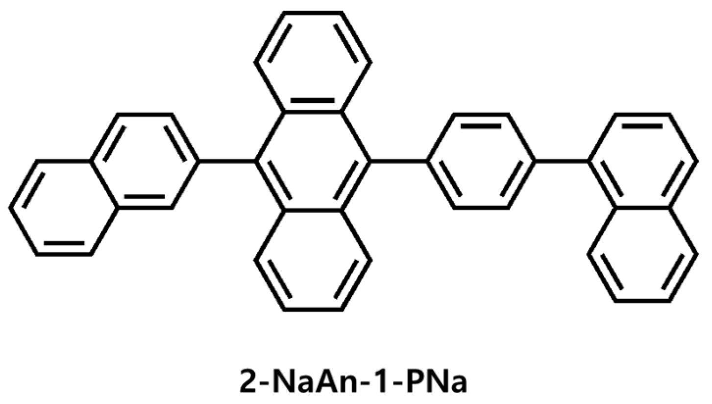
Scheme 1 illustrates the synthetic routes of the synthesized 2NaAn-1-PNa. The final product was synthesized through borylation, bromination, and Suzuki coupling and purified by silica column chromatography or the reprecipitation method. The synthesized compounds were structurally confirmed by nuclear magnetic resonance, elemental analysis, and mass spectrometry (Figures S1–S3). The synthesized 2NaAn-1-PNa possesses an anthracene core chromophore with aryl groups and an asymmetric structure (Figure 1).
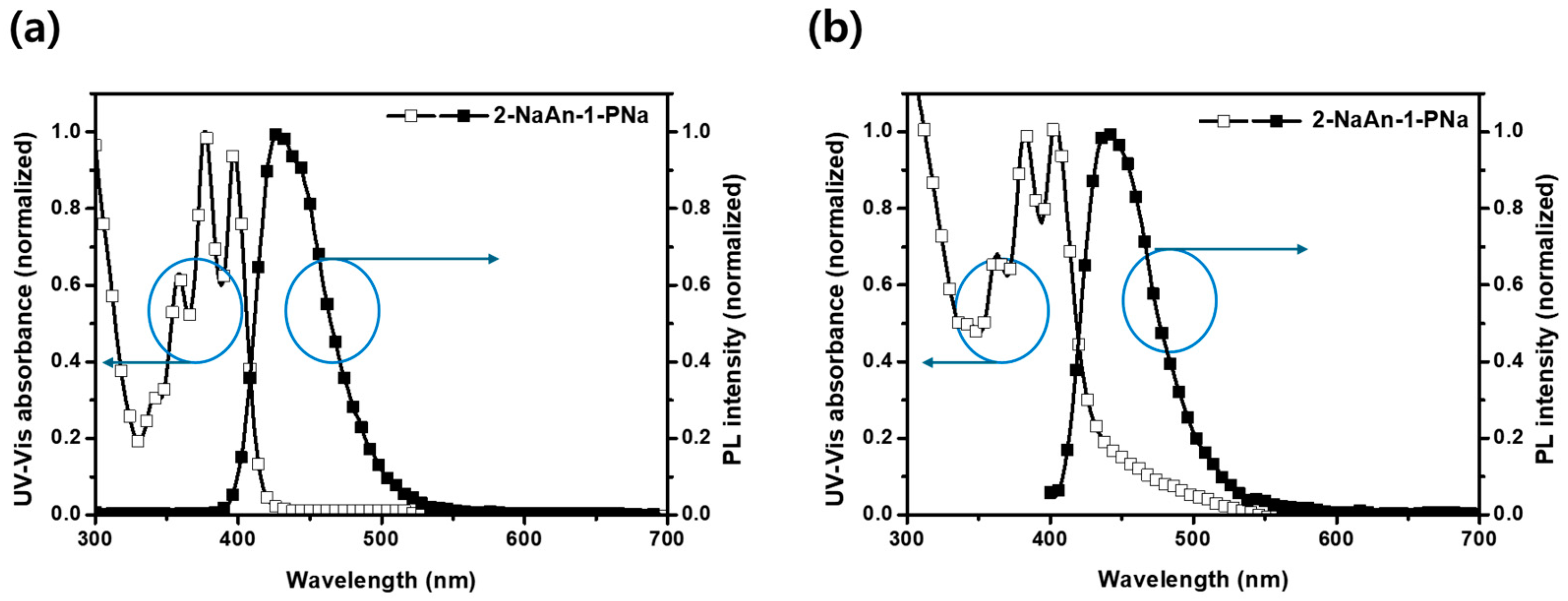
The photophysical properties of the synthesized compound were investigated by UV–Visible absorption (UV–Vis) and photoluminescence spectra in toluene solution (10−5 M) and film states, as shown in Table 1 and Figure 2. In the solution state, 2-NaAn-1-PNa exhibited UV–Vis peaks at 340, 359, 376, and 397 nm, with a maximum photoluminescence (PLmax) at 428 nm. The peaks at 359, 376, and 397 nm corresponded to characteristic vibration peaks of the anthracene molecule. In the vacuum-deposited film, the UV–Vis peaks of the compound were observed at 363, 383, and 403 nm, with a PLmax at 440 nm. From the solution state to the film state, the PLmax exhibited a red shift of approximately 12 nm, likely due to π-π * interactions between molecules in the film. The full-width half maximum (FWHM) values of 2-NaAn-1-PNa were 53 nm in the solution state and 56 nm in the film state. The MNAn compound previously reported by by Kwon et al. had a twisted angle of 79.77° between the 2-naphthyl group and anthracene [24]. In the solution state, the torsion angle between anthracene and the naphthyl group is expected to exhibit a highly twisted structure similar to the values predicted by molecular calculations. However, in the film state, it is anticipated that a moderately twisted structure will be maintained to ensure stability.
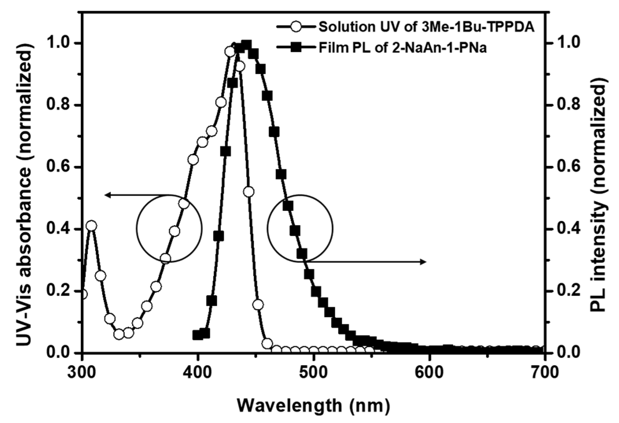
The highly twisted molecular structure between the core group and side group hinders intermolecular interactions, resulting in relatively narrow FWHM values even in the film state compared to those in the solution state. Moreover, preventing intermolecular interactions results in a non-planar structure that reduces self-aggregation, thereby inhibiting re-crystallization and forming morphologically stable films in OLED devices [25]. The photoluminescence quantum yield (PLQY) of 2-NaAn-1-PNa was 73.1% in the solution state and 30.2% in the film state. The fluorescence lifetime of 2-NaAn-1-PNa was 2.99 ns, and the transient PL spectrum is shown in Figure S4. 2-NaAn-1-PNa exhibited a krad of 2.44 × 10⁸/s and a knr of 9.04 × 10⁷/s. Therefore, the krad/knr value for 2-NaAn-1-PNa was 2.69 (Table S1). To confirm the potential of 2-NaAn-1-PNa as a blue host, the PL spectrum of 2-NaAn-1-PNa in the film state was observed to overlap with the absorption spectrum of the previously reported 3Me-1Bu-TPPDA in the solution state (Figure 3). In the doped device fabricated via evaporated system, the EML consists of 2-NaAn-1-PNa: 4 wt% 3Me-1Bu-TPPDA. Therefore, when the host, comprising 96 wt%, emits similarly to its film state in PL, the emitted energy is absorbed by the dopant, 3Me-1Bu-TPPDA. Given the low wt% of the dopant compared to the host, the environment resembles that of a solution with very weak intermolecular forces. Therefore, for the dopant, UV–Vis in solution is used to confirm the overlap of the two spectra, ensuring efficient energy transfer from the host to the dopant. Given the proven characteristics of 3Me-1Bu-TPPDA as a blue dopant material in our previous research, including high efficiency, real blue emission, and long device lifetime, it was used as the dopant material in this study. The two spectra were sufficiently overlapped, indicating efficient Förster energy transfer from the blue dopant material to 2-NaAn-1PNa. HOMO levels for both compounds were measured using AC-2, and the LUMO levels were calculated from the HOMO levels and optical band gaps. There are two methods commonly used to calculate the optical band gap: one involves determining the band edge from the absorbance spectrum, and the other utilizes the () versus (αhν)2 plot to identify the absorbance edge [26,27]. In this paper, the optical band gap was determined by identifying the absorbance edge from the () versus (αhν)2 plot, where α, h, and ν denote absorbance, Planck’s constant, and the frequency of light, respectively. The HOMO and LUMO levels of 2-NaAn-1-PNa were −5.84 eV and −2.89 eV, with a band gap of 2.95 eV. The HOMO and LUMO levels of the dopant 3Me-1Bu-TPPDA used were −5.84 eV and −2.89 eV, respectively [22]. The HOMO level was measured using AC-2 equipment. Additionally, the experimental HOMO value was determined using cyclic voltammetry (CV). The HOMO level of 2-NaAn-1-PNa, derived from the oxidation peaks, was found to be −6.01 eV (Figure S6). The LUMO levels were calculated from the band gap values obtained from the absorbance edge, resulting in a value of −3.06 eV. Thus, the measurements from CV and AC-2 were consistent. In the solution, the band gap is 3.03 eV, while in the film state it is 2.95 eV, showing a difference of 0.08 eV. Despite their similarity, the band gap is slightly smaller in the film state, a reduction typically attributed to enhanced intermolecular interactions resulting from closer molecular packing. Such interactions influence the electronic structure of the molecules, commonly resulting in a smaller band gap.

3.2. Thermal Properties

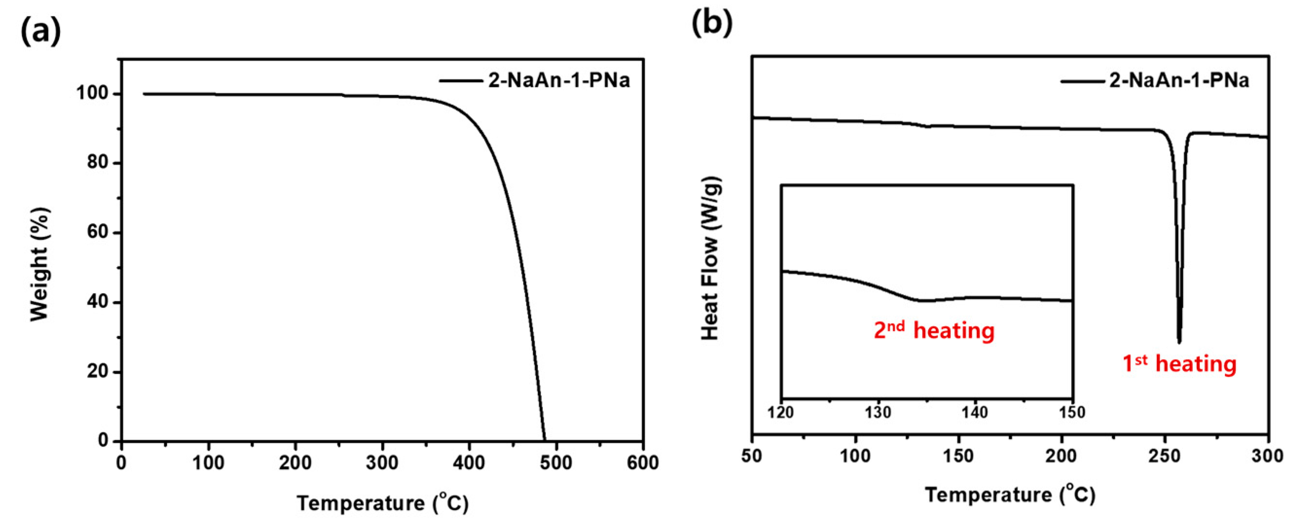
Figure 4 illustrates the thermal properties of 2-NaAn-1-PNa as determined by TGA and DSC. A summary of the thermal properties of the compound is provided in Table S2. According to the TGA results, the Td of 2-NaAn-1-PNa, defined as the temperature at which 5% weight loss occurs, was 391 °C. The Tm was determined to be 248 °C. Tg was observed at 134 °C. These results demonstrate excellent thermal stability compared to reported anthracene derivatives used as host materials [17]. Excellent thermal stability, such as Tg values exceeding 100 °C, is highly desirable for OLED stability, suggesting a high operational lifetime of OLEDs. OLED materials with high Tg values can contribute to device stability and lifetime [5,28].

3.3. Electroluminescence Properties

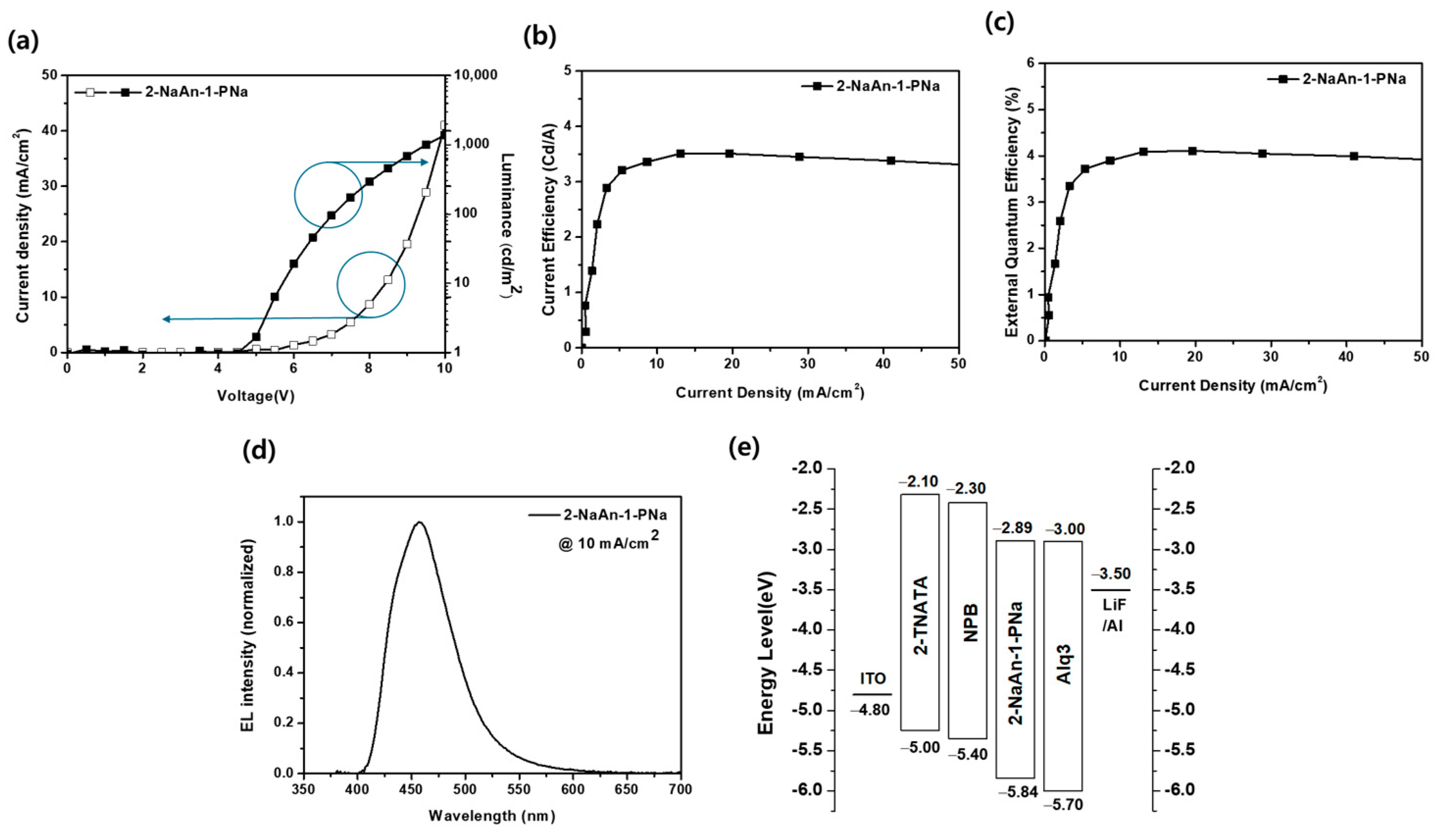
Non-doped OLED devices were fabricated using 2-NaAn-1-PNa as the emitting layer. As shown in Figure 5, the non-doped device was prepared as follows: ITO (150 nm)/2-TNATA (60 nm)/NPB (20 nm)/2-NaAn-1-PNa (35 nm)/Alq3 (15 nm)/LiF (1 nm)/Al (200 nm). 2-TNATA, NPB, and Alq3 were utilized as the HIL, HTL, and ETL, respectively. Chemical structures of materials for non-doped OLED devices are depicted in Figure S7. Figure 5a–d illustrate the current density (J)-voltage (V)-luminance (L) curves, CE-J, EQE-J, and EL spectrum of the fabricated non-doped OLED devices. The EL characteristics of the non-doped device are summarized in Table 2. The non-doped OLED device exhibited typical J-V-L curves and an operating voltage (O.V.) of approximately 8.1 V at 10 mA/cm2. As shown in Figure 5d, the EL spectrum emitted light with a maximum peak at 457 nm and CIE (x, y) values of (0.150, 0.113). The CE was 3.4 cd/A, EQE was 3.9%, and luminance was 335 cd/m2. Consequently, it was confirmed that 2-NaAn-1-PNa can emit blue light as a host material. The non-doped and doped devices fabricated in this study used different structures to meet their respective purposes. The HIL and HTL used in the non-doped device were configured to verify the EL wavelength and I-V-L characteristics of the host material itself, and this device structure is well-known for evaluating blue emissive materials. The doped device structure, using different HIL and HTL compared to the non-doped device, was optimized for high efficiency and long device lifetime, using a structure that our lab has previously reported to be optimized for the dopant. Therefore, even if similar HIL and HTL were used in both structures, the efficiency of the non-doped device would be lower than that of the doped device due to the absence of a dopant. If an EBL with suitable energy levels is introduced into the non-doped device, it is possible to form an increased recombination zone and decreased polaron-induced stress at the interface [29].
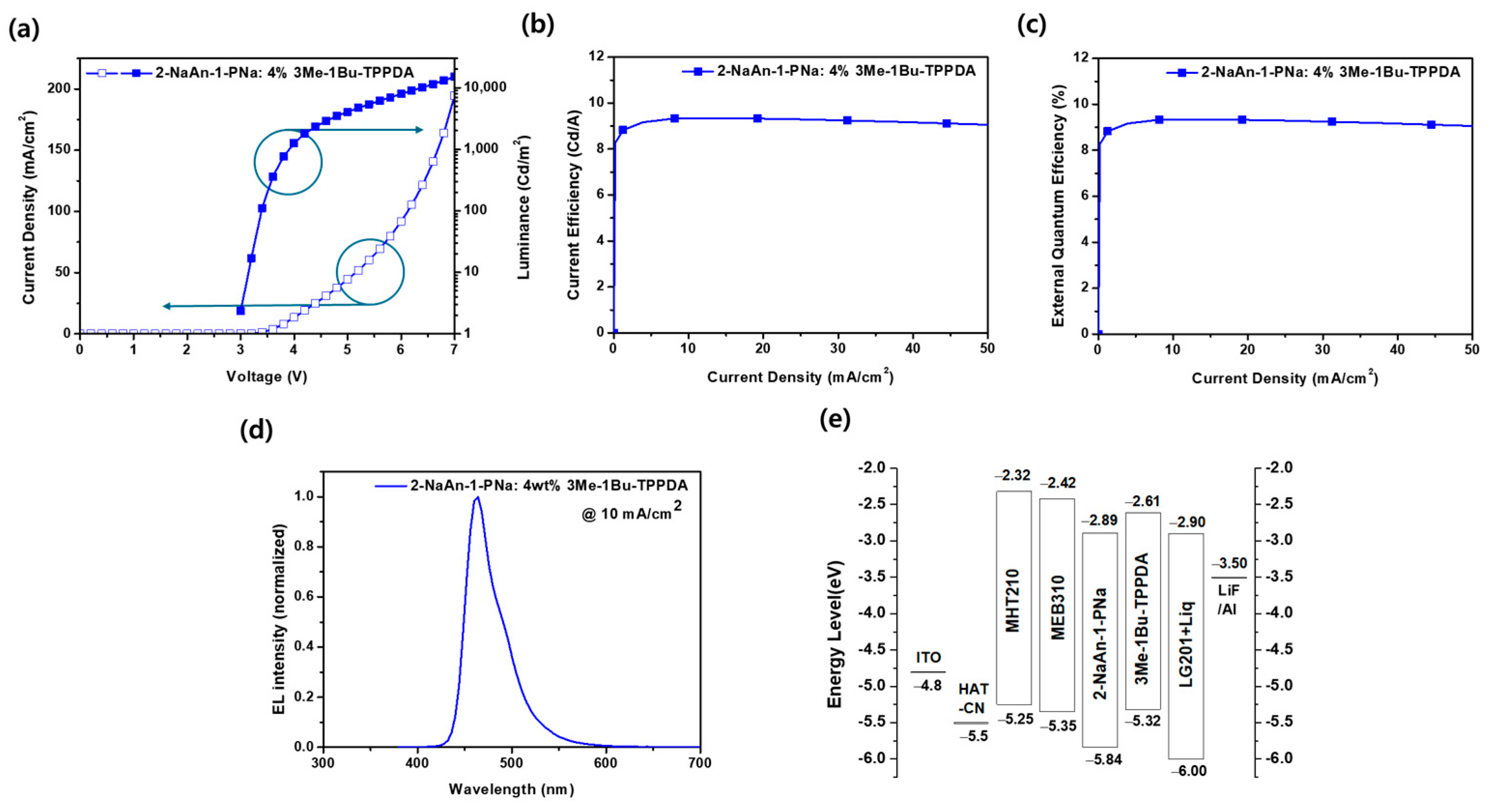
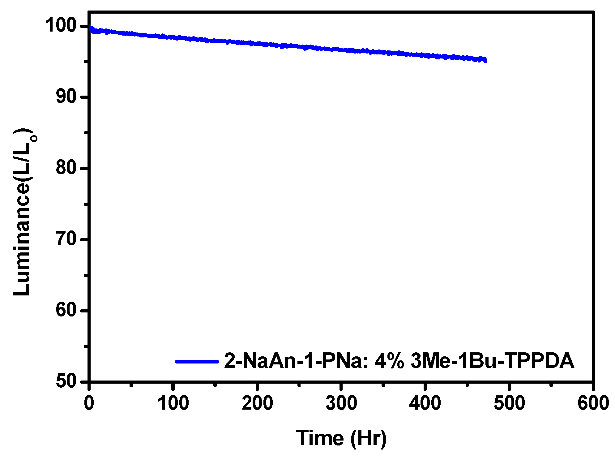
To verify the potential of 2-NaAn-1-PNa as a blue host, doped devices were fabricated, and the EL characteristics of the OLED doped device are shown in Figure 6 and Table 2. Utilizing a doped device has the advantage of achieving higher efficiency by suppressing luminescence quenching caused by molecular packing, which typically occurs in non-doped devices [30]. The doped device was composed of ITO (150 nm)/HAT-CN (10 nm)/MHT210 (100 nm)/MEB310 (10 nm)/2-NaAn-1-PNa: 4% 3Me-1Bu-TPPDA (20 nm)/LG201 + 80% Liq (24 nm)/LiF/Al. The HIL, HTL, and EBL-HTL utilized HAT-CN, MHT210, and MEB310, respectively, with LG201 and Liq serving as the ETL. We verified the thickness of the EML films using the thickness monitor of the evaporation equipment during film and device fabrication. Additionally, we cross-checked the thickness of the films produced under the same conditions as the devices using an alpha step instrument (Figure S8). The doped device also exhibited typical J-V-L curves and a low O.V. of 3.9 V at 10 mA/cm2. When using the optimized structure of the doped device, the operating voltage decreased by approximately 50%, from 8.1 V to 3.9 V, due to the lower energy barrier compared to the non-doped device. Additionally, it showed CIE (x, y) values of (0.134, 0.139), CE of 9.3 cd/A, EQE of 8.3%, and luminance of 934 cd/m2 (Figure 6). In Figure 6d, the peak ELmax is observed at 460 nm, closely matching the shape of the PL spectrum and the PLmax value of the blue dopant material 3Me-1Bu-TPPDA in solution, as shown in Figure S5. Furthermore, when comparing the shape of the EL spectrum of the doped device with the PL spectrum of 3Me-1Bu-TPPDA in the solution state and comparing their FWHM values, which were both 41 nm, it indicates that the EL spectrum originates from emission by the dopant. Efficient energy transfer from the host to the dopant was confirmed, as described in Figure 3. Furthermore, as depicted in Figure 6c, the device showed minimal roll-off. The doped device exhibited a 1.9% decrease in EQE at 4000 nits compared to the maximum value. When 2-NaAn-1-PNa was used as the host, it exhibited very stable roll-off characteristics. Wei et al. reported on four host materials based on anthracene [21]. Among them, NA-AN-NA, which has a molecular structure most similar to 2-NaAn-1-PNa, was used as a host, and when doped with 5 wt% DITBDAP, achieved a CEmax of 8.97 cd/A and EQEmax of 8.10%, demonstrating excellent EL characteristics. Comparing these results, it can be inferred that 2-NaAn-1-PNa can also effectively enhance EL performance due to balanced charge transport and efficient exciton recombination. The stability of the fabricated doped OLED devices was assessed by measuring their lifetime at 1000 cd/m2. The LT95 values were 440 h, indicating excellent device longevity surpassing 400 h (Figure 7). LT95 denotes the device lifetime where the final luminance reaches 95% of the initial luminance. Extrapolated to LT50, the doped device is estimated to have a lifetime exceeding 28,000 h [22]. Asymmetric anthracene-based devices may offer extended lifetimes, possibly attributed to improved thermal stability. Due to their high luminous efficiency, low operating voltages, and prolonged lifetimes, these devices are suitable not only for mobile phones but also for OLED TVs, which require low power consumption and long-lasting performance.

4. Conclusions

We synthesized a novel blue host material, 2-NaAN-1-PNa, which, owing to its asymmetric structure, effectively prevents molecular packing in the solid state and provides steric hindrance to form thermally stable amorphous films. Consequently, it exhibited excellent thermal properties with a Tg value exceeding 130 °C. The doped device utilizing 2-NaAn-1-PNa as the host showed a low O.V. of 3.9 V at 10 mA/cm2 and emitted light in the real blue region with CIE coordinates of (0.134, 0.139) and a peak wavelength of 460 nm. It demonstrated a CE of 9.3 cd/A, an EQE of 8.3%, and a luminance of 934 cd/m2. Regarding EQE roll-off, it exhibited a very low level of roll-off, reaching only 1.9% at 4000 nits. The LT95 measurement for OLED device lifetime was approximately 440 h. With its high efficiency and longevity, 2-NaAn-1-PNa shows promise for various display applications.

Supplementary Materials

The following supporting information can be downloaded at: https://www.mdpi.com/article/10.3390/app14135716/s1, Figure S1: 1H-NMR spectrum of compound (1); Figure S2: 1H-NMR spectrum of compound (2); Figure S3: 1H-NMR spectrum of 2-NaAn-1PNa; Figure S4: Transient PL spectrum of 2-NaAn-1-PNa in solution state (10−5 M in toluene).; Figure S5: PL spectrum of 3Me-1Bu-TPPDA in solution state (10−5 M in toluene).; Figure S6: Cyclic voltammograms under 100 mV/s of 2-NaAn-1-PNa [0.1 M TBAP-F6 in dichloromethane reference electrode: Ag/AgCl].; Figure S7: Chemical structures of materials used for OLED devices fabrication. Figure S8: Thickness profile images (a) 2-NaAn-1-PNa evaporated film (thickness: 35 nm), (b) 2-NaAn-1-PNa: 4% 3Me-1Bu-TPPDA evaporated film (thickness: 20 nm); Table S1: Photophysical properties of the synthesized compound; Table S2: Thermal properties of the synthesized materials.

Author Contributions

Conceptualization, H.K. and S.O.; methodology, H.K.; validation, H.L. and J.P.; formal analysis, S.P. (Sunwoo Park) and H.L.; investigation, S.P. (Sangwook Park) and S.O.; resources, J.P.; writing—original draft preparation, H.K., S.O. and J.P.; writing—review and editing, H.L. and J.P.; visualization, H.K., S.P. (Sangwook Park) and S.P. (Sunwoo Park); supervision, J.P.; project administration, J.P.; funding acquisition, J.P. All authors have read and agreed to the published version of the manuscript.

Funding

This work was supported by the GRRC program of Gyeonggi province. [(GRRCKYUNGHEE2023-B01), Development of ultra-fine process materials based on the sub-nanometer class for the next-generation semiconductors].

Institutional Review Board Statement

Not applicable.

Informed Consent Statement

Not applicable.

Data Availability Statement

Data are contained within the article and Supplementary Materials.

Conflicts of Interest

The authors declare no conflicts of interest.

References

  1. Pickup, D.F.; Yi, H.; Kun, H.; Iraqi, A.; Stevenson, M.; Lidzey, D.G. Alternating 2, 7-and 3, 6-linked carbazole copolymers as wide band gap energy transfer donors. Thin Solid Films 2009, 517, 2840–2844. [Google Scholar] [CrossRef]
  2. Liu, J.; Guo, X.; Bu, L.; Xie, Z.; Cheng, Y.; Geng, Y.; Wang, L.; Jing, X.; Wang, F. White Electroluminescence from a Single-Polymer System with Simultaneous Two-Color Emission: Polyfluorene Blue Host and Side-Chain-Located Orange Dopant. Adv. Funct. Mater. 2007, 17, 1917–1925. [Google Scholar] [CrossRef]
  3. Lee, J.Y.; Kwon, Y.J.; Woo, J.W.; Moon, D.K. Synthesis and characterization of fluorine–thiophene-based π-conjugated polymers using coupling reaction. J. Ind. Eng. Chem. 2008, 14, 810–817. [Google Scholar] [CrossRef]
  4. Kang, I.; Hong, J.A.; Kim, R.; Jang, J.W.; Hwang, J.; Kim, J.H.; Kwon, S.K.; Kim, Y.H. Synthesis and characterization of a new π-conjugated polymer with cyanoacrylate side chain for organic thin film transistors. Macromol. Res. 2013, 21, 450–455. [Google Scholar] [CrossRef]
  5. Kang, S.W.; Kwon, H.M.; Pu, Y.-J.; Park, J. High-efficiency deep-blue emitter consisting of a chrysene core and optimized side groups. Mater. Today Energy 2021, 21, 100706. [Google Scholar]
  6. Yook, S.; Jeon, S.; Kim, O.; Lee, J. Lifetime study of red phosphorescent organic light-emitting diodes with a double doping structure. J. Ind. Eng. Chem. 2010, 16, 813–815. [Google Scholar] [CrossRef]
  7. Lee, Y.; Lee, H.; Kang, S. Fabrication of highly efficient and stable doped red organic light-emitting device using 2-methyl-9,10-di(2-napthyl)anthracene and tris(8-hydroxyquinolinato)aluminum as cohost materials. Appl. Phys. Lett. 2006, 89, 183515. [Google Scholar] [CrossRef]
  8. Aydemir, M.; Haykır, C.; Battal, A.; Jankus, V.; Sugunan, S.K.; Dias, F.B.; Al-Attar, H.; Türksoy, F.; Tavaslı, M.; Monkman, A.P. High efficiency OLEDs based on anthracene derivatives: The impact of electron donating and withdrawing group on the performance of OLED. Org. Electron. 2016, 30, 49–157. [Google Scholar] [CrossRef]
  9. Hwang, H.; We, H.; Bian, G.; Song, L. An Anthracene-Based Bis-Stilbene Derivative as Luminescent Materials for Organic Light Emitting Diodes. Materials 2023, 16, 3685. [Google Scholar] [CrossRef]
  10. Zheng, C.-J.; Zhao, W.-M.; Wang, Z.-Q.; Huang, D.; Ye, J.; Qu, X.-M.; Zhang, X.-H.; Lee, C.-S.; Lee, S.-T. Highly efficient non-doped deep-blue organic light-emitting diodes based on anthracene derivatives. J. Mater. Chem. 2010, 20, 1560–1566. [Google Scholar] [CrossRef]
  11. Hu, J.-Y.; Pu, Y.-J.; Satoh, F.; Kawata, S.; Katagiri, H.; Sasabe, H.; Kido, J. Bisanthracene-Based Donor–Acceptor-type Light-Emitting Dopants: Highly Efficient Deep-Blue Emission in Organic Light-Emitting Devices. Adv. Funct. Mater. 2014, 24, 2064–2071. [Google Scholar] [CrossRef]
  12. Chiang, C.-J.; Kimyonok, A.; Etherington, M.K.; Griffiths, G.C.; Jankus, V.; Turksoy, F.; Monkman, A.P. Ultrahigh Efficiency Fluorescent Single and Bi-Layer Organic Light Emitting Diodes: The Key Role of Triplet Fusion. Adv. Funct. Mater. 2013, 23, 739–746. [Google Scholar] [CrossRef]
  13. Hayashi, H.; Kato, Y.; Matsumoto, A.; Shikita, S.; Aizawa, N.; Suzuki, M.; Aratani, N.; Yasuda, T.; Yamada, H. Synthesis of Anthracene Derivatives with Azaacene-Containing Iptycene Wings and the Utilization as a Dopant for Solution-Processed Organic Light-Emitting Diodes. Chem. Eur. J. 2019, 25, 15565–15571. [Google Scholar] [CrossRef] [PubMed]
  14. Park, S.; Kang, S.; Park, S.; Kwon, H.; Lee, H.; Lee, K.; Park, J. Novel Fused Core Chromophore Incorporating Spirofluorene and Anthracene Groups for Sky-Blue Emission and Solution-Processed White Devices. Appl. Sci. 2023, 13, 1054. [Google Scholar] [CrossRef]
  15. Park, D.; Kang, S.; Ryoo, C.H.; Jhun, B.H.; Jung, S.; Le, T.N.; Suh, M.C.; Lee, J.; Jun, M.E.; Chu, C.; et al. High-performance blue OLED using multiresonance thermally activated delayed fluorescence host materials containing silicon atoms. Nat. Commun. 2023, 14, 5589. [Google Scholar] [CrossRef] [PubMed]
  16. Rothmann, M.M.; Hanader, S.; Como, E.D.; Lennartz, C.; Schildknecht, C.; Strohriegl, P. Donor-Substituted 1,3,5-Triazines as Host Materials for Blue Phosphorescent Organic Light-Emitting Diodes. Chem. Mater. 2010, 22, 2403. [Google Scholar] [CrossRef]
  17. Wee, J.-R.; Han, W.-S.; Kim, J.-E.; Kim, A.-L.; Kwon, S.; Kang, S.O. Asymmetric anthracene-based blue host materials: Synthesis and electroluminescence properties of 9-(2-naphthyl)-10-arylanthracenes. J. Mater. Chem. 2011, 21, 1115–1123. [Google Scholar] [CrossRef]
  18. Shirota, Y. Organic materials for electronic and optoelectronic devices. J. Mater. Chem. 2000, 10, 1–25. [Google Scholar] [CrossRef]
  19. Zhao, X.; Wang, S.; You, J.; Zhang, Y.; Li, X. Solution-processed thermally stable amorphous films of small molecular hole injection/transport bi-functional materials and their application in high efficiency OLEDs. J. Mater. Chem. C 2015, 3, 11377–11384. [Google Scholar] [CrossRef]
  20. Lyu, Y.-Y.; Kwak, J.; Kwon, O.; Lee, S.-H.; Kim, D.; Lee, C.; Char, K. Silicon-Cored Anthracene Derivatives as Host Materials for Highly Efficient Blue Organic Light-Emitting Devices. Adv. Mater. 2008, 20, 2720–2729. [Google Scholar] [CrossRef]
  21. Sun, T.; Shui, X.; Chen, W.; Chen, Y.; Shi, W.; Huang, J.; Wei, B. Efficient and low roll-off deep-blue organic light-emitting diodes with anthracene-based compounds as hosts. New J. Chem. 2024, 48, 1867–1875. [Google Scholar] [CrossRef]
  22. Jung, H.; Kang, S.; Lee, H.; Yu, Y.-J.; Jeong, J.H.; Song, J.; Jeon, Y.; Park, J. High Efficiency and Long Lifetime of a Fluorescent Blue-Light Emitter Made of a Pyrene Core and Optimized Side Groups. Appl. Mater. Interfaces 2018, 10, 30022–30028. [Google Scholar] [CrossRef] [PubMed]
  23. Forrest, S.R.; Bradley, D.D.C.; Thompson, M.E. Measuring the Efficiency of Organic Light-Emitting Devices. Adv. Mater. 2003, 15, 1043–1048. [Google Scholar] [CrossRef]
  24. Shin, M.-G.; Kimg, S.O.; Park, H.T.; Park, S.J.; Yu, H.S.; Kim, Y.-H.; Kwon, S.-K. Synthesis and characterization of ortho-twisted asymmetric anthracene derivatives for blue organic light emitting diodes (OLEDs). Dyes. Pigments 2012, 92, 1075–1082. [Google Scholar] [CrossRef]
  25. Wang, L.; We, Z.-Y.; Wong, W.-Y.; Cheah, K.-W.; Huang, H.; Chen, C.H. New blue host materials based on anthracene-containing dibenzothiophene. Org. Electron. 2011, 12, 595–601. [Google Scholar] [CrossRef]
  26. Costa, J.C.S.; Taveira, J.S.; Lima, F.R.A.C.; Mendes, A.; Santos, M.N.B.F. Optical band gaps of organic semiconductor materials. Opt. Mater. 2016, 58, 51–60. [Google Scholar] [CrossRef]
  27. Onoda, M.; Tada, K. A consideration of thermochromic behavior in poly(p-phenylenevinylene) derivatives. Thin Solid Films 2003, 438–439, 187–194. [Google Scholar] [CrossRef]
  28. Park, Y.; Kim, B.; Lee, C.; Hyun, A.; Jang, S.; Lee, J.; Gal, Y.S.; Kim, T.; Kim, K.; Park, J. Highly efficient new hole injection materials for OLEDs based on dimeric phenothiazine and phenoxazine derivatives. J. Phys. Chem. C 2011, 115, 4843–4850. [Google Scholar] [CrossRef]
  29. Shin, J.; Lee, J. Hole injection control of electron blocking layer for broad recombination zone and low-efficiency roll-off in phosphorescent organic light emitting device. J. Inf. Disp. 2023, 1–10. [Google Scholar] [CrossRef]
  30. Fukagawa, H.; Shimizu, T.; Kamada, T.; Yui, S.; Hasegawa, M.; Morii, K.; Yamamoto, T. Highly efficient and stable organic light-emitting diodes with a greatly reduced amount of phosphorescent emitter. Sci. Rep. 2015, 5, 9855. [Google Scholar] [CrossRef]
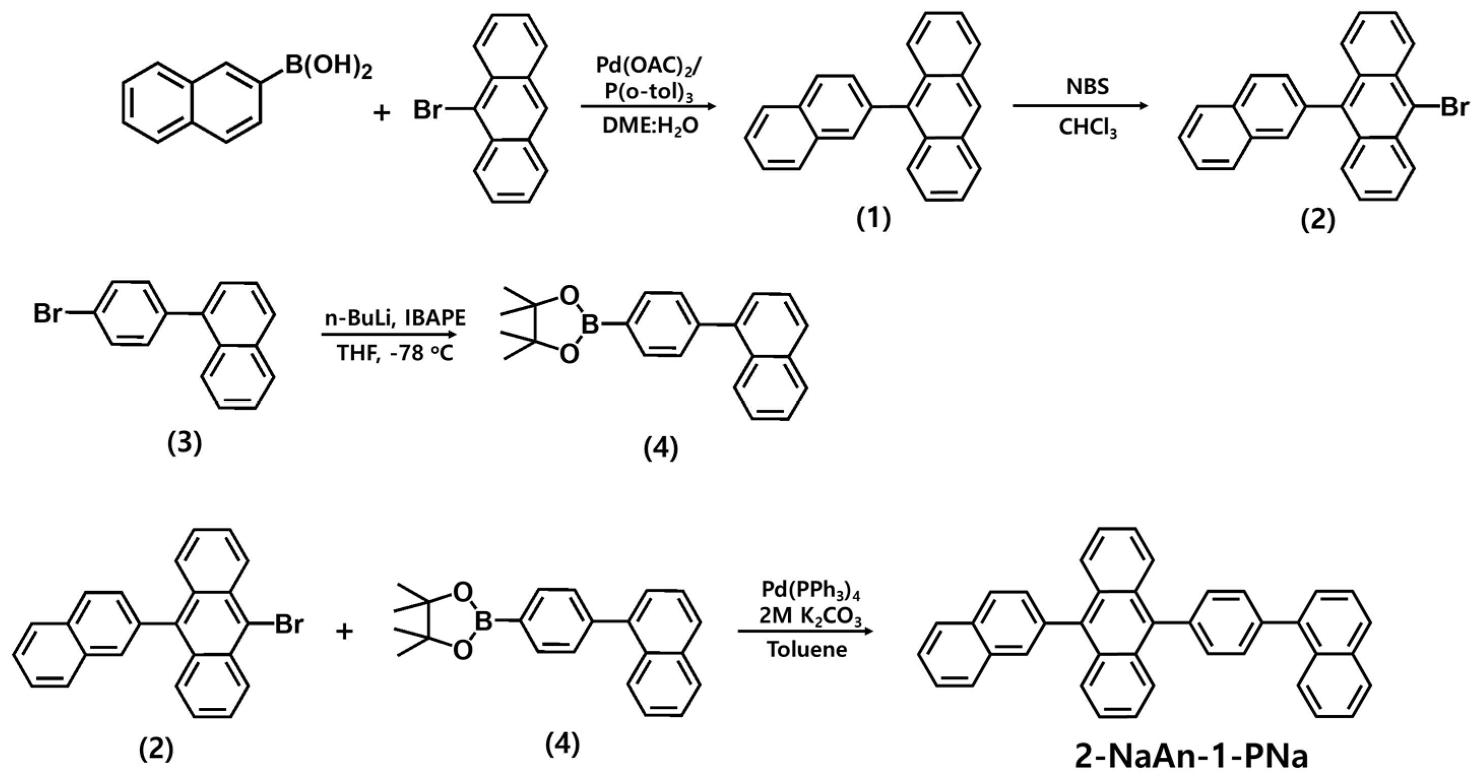
Scheme 1. Synthetic routes of newly synthesized compound.
Applsci 14 05716 sch001
Figure 1. Chemical structure of the 2-NaAn-1-PNa.
Applsci 14 05716 g001
Figure 2. UV−Vis absorption (left arrow) and PL spectra (right arrow) of anthracene derivatives in (a) solution state (toluene, 1 × 10⁻⁵ M) and (b) film state (thickness: 50 nm).
Applsci 14 05716 g002
Figure 3. Absorption spectrum (O, left arrow) of 3Me-1Bu-TPPDA dopant in solution and PL spectrum (■, right arrow) of 2-NaAN-1-PNa film.
Applsci 14 05716 g003
Figure 4. Thermal properties of 2-NaAn-1-PNa: (a) TGA and (b) DSC in 1st heating (inset: Expansion of the Tg region in 2nd heating).
Applsci 14 05716 g004
Figure 5. EL characteristics of non-doped device using 2-NaAn-1-PNa: (a) J-V-L curve (left arrow: current density, right arrow: luminance), (b) luminance efficiency versus current density, (c) external quantum efficiency versus current density, (d) EL spectrum of OLED non-doped device at 10 mA/cm2, and (e) band diagrams of the fabricated non-doped OLED device.
Applsci 14 05716 g005
Figure 6. EL characteristics of doped device using 2-NaAn-1-PNa: 4 wt% 3Me-1Bu-TPPDA: (a) J-V-L curve (left arrow: current density, right arrow: luminance), (b) luminance efficiency versus current density, (c) external quantum efficiency versus current density, (d) EL spectrum of OLED doped device at 10 mA/cm2, and (e) energy level diagrams of the fabricated doped OLED device.
Applsci 14 05716 g006
Figure 7. Device lifetime of OLED doped device.
Applsci 14 05716 g007
Table 1. Optical properties of the synthesized materials.
CompoundSolution aFilm bHO
MO c
(eV)
LU
MO
(eV)
Band Gap a/b
(eV)
λAbs
(nm)
λPL (FWHM) (nm)ΦF (%)λAbs (nm)λPL (FWHM) (nm)ΦF
(%)
2-NaAn-1-PNa340, 359, 376, 397428
(53)
73.1363, 383, 403440
(56)
30.2−5.84−2.893.03/
2.95
a Toluene solution (0.5 wt%), b in thin film state (thickness: 50 nm), c HOMO values derived from ultraviolet photoelectron spectra (Riken-Keiki, AC-2).
Table 2. EL performances of the fabricated OLED non-device and doped device at 10 mA/cm2.
DeviceO.V. a
(V)
Luminance
(cd/m2)
CE
(cd/A)
EQE
(%)
ELmax
(nm)
FWHM (nm)CIE
(x, y)
Non-doped8.13353.43.945765(0.150, 0.113)
Doped3.99349.38.346053(0.134, 0.139)
a Operating voltage at 10 mA/cm2.
Disclaimer/Publisher’s Note: The statements, opinions and data contained in all publications are solely those of the individual author(s) and contributor(s) and not of MDPI and/or the editor(s). MDPI and/or the editor(s) disclaim responsibility for any injury to people or property resulting from any ideas, methods, instructions or products referred to in the content.